Tiltrotor articulated wing extension
Ivans , et al. Sept
U.S. patent number 10,414,483 [Application Number 15/271,721] was granted by the patent office on 2019-09-17 for tiltrotor articulated wing extension. This patent grant is currently assigned to Bell Helicopter Textron, Inc.. The grantee listed for this patent is Bell Helicopter Textron, Inc.. Invention is credited to Steven Ray Ivans, Brent Chadwick Ross.


| United States Patent | 10,414,483 |
| Ivans , et al. | September 17, 2019 |
Tiltrotor articulated wing extension
Abstract
An aircraft has a wing, a pylon carried by the wing, at least one of a rotor system component and a drive system component disposed within the pylon, and a wing extension carried by the at least one of a rotor system component and drive system component, wherein the wing extension is foldable relative to the pylon to selectively reduce an overall space occupied by the aircraft.
| Inventors: | Ivans; Steven Ray (Ponder, TX), Ross; Brent Chadwick (Flower Mound, TX) | ||||||||||
|---|---|---|---|---|---|---|---|---|---|---|---|
| Applicant: |
|
||||||||||
| Assignee: | Bell Helicopter Textron, Inc.
(Fort Worth, TX) |
||||||||||
| Family ID: | 61617830 | ||||||||||
| Appl. No.: | 15/271,721 | ||||||||||
| Filed: | September 21, 2016 |
Prior Publication Data
| Document Identifier | Publication Date | |
|---|---|---|
| US 20180079487 A1 | Mar 22, 2018 | |
| Current U.S. Class: | 1/1 |
| Current CPC Class: | B64C 1/30 (20130101); B64C 27/50 (20130101); B64C 1/26 (20130101); B64C 29/0033 (20130101); B64C 11/28 (20130101); B64C 3/56 (20130101) |
| Current International Class: | B64C 3/56 (20060101); B64C 27/50 (20060101); B64C 11/28 (20060101); B64C 1/30 (20060101); B64C 1/26 (20060101); B64C 29/00 (20060101) |
| Field of Search: | ;244/17.27 |
References Cited [Referenced By]
U.S. Patent Documents
| 2289224 | July 1942 | Swanson et al. |
| 2623713 | December 1952 | Foster |
| 3063660 | November 1962 | Jarrell |
| 3430894 | March 1969 | Strand et al. |
| 4691878 | September 1987 | Vaughan |
| 5310138 | May 1994 | Fitzgibbon |
| 5337974 | August 1994 | Rumberger et al. |
| 7802754 | September 2010 | Karem |
| 8083172 | December 2011 | Karem |
| 8439314 | May 2013 | Dhall |
| 9102401 | August 2015 | Collins et al. |
| 9550567 | January 2017 | Erdozain, Jr. |
| 9981734 | May 2018 | Ivans |
| 10167080 | January 2019 | Foskey |
| 2012/0292436 | November 2012 | Karem |
| 2016/0311553 | October 2016 | Alber |
| 2017/0297698 | October 2017 | Alber |
| 2018/0079484 | March 2018 | Ross |
| 2018/0079502 | March 2018 | Foskey |
| 100822366 | Apr 2008 | KR | |||
| 2009102739 | Aug 2009 | WO | |||
| 2010104509 | Sep 2010 | WO | |||
| 2011018697 | Feb 2011 | WO | |||
| 2013015295 | Jan 2013 | WO | |||
Other References
|
European Search Report; European Application No. 16203012.6; dated Nov. 9, 2017; 7 pages. cited by applicant . Partial European Search Report; European Application No. 16203012.6; dated Jun. 9, 2017; 16 pages. cited by applicant . European Exam Report; European Application No. 16203012.6; dated Dec. 4, 2017; 10 pages. cited by applicant. |
Primary Examiner: Ellis; Christopher P
Attorney, Agent or Firm: Lightfoot & Alford PLLC
Claims
What is claimed is:
1. An aircraft, comprising: a wing comprising a spanwise axis; a pylon carried by the wing; at least one of a rotor system component and a drive system component disposed within the pylon; and a wing extension carried by an external case of a proprotor gearbox; wherein the wing extension is foldable relative to the pylon to selectively reduce an overall space occupied by the aircraft; and wherein the pylon is rotatable relative to the wing about the spanwise axis.
2. The aircraft of claim 1, wherein the wing extension is connected to the case using a mount.
3. The aircraft of claim 2, wherein a first hinge portion is connected to the mount.
4. The aircraft of claim 3, wherein a second hinge portion is connected between the wing extension and the first hinge portion.
5. The aircraft of claim 4, wherein the wing extension comprises a strut connected to the second hinge portion.
6. The aircraft of claim 5, wherein the wing extension comprises a skin carried by the strut.
7. The aircraft of claim 6, wherein the wing extension is a dihedral wing extension.
8. The aircraft of claim 1, wherein a shape of the wing extension is complementary to the pylon.
9. The aircraft of claim 1, wherein the wing extension is configured to selectively fold to a position at least partially located above the pylon.
10. The aircraft of claim 1, wherein the wing extension is configured to selectively fold to a position at least partially located below the pylon.
Description
CROSS-REFERENCE TO RELATED APPLICATIONS
Not applicable
STATEMENT REGARDING FEDERALLY SPONSORED RESEARCH OR DEVELOPMENT
Not applicable.
REFERENCE TO A MICROFICHE APPENDIX
Not applicable.
BACKGROUND
In some cases, wing extensions are provided to aircraft by attaching wing extensions to nacelles or pylons. While the wing extensions carried by the nacelles or pylons can allow improved efficiency, such as improved efficiency of a tiltrotor aircraft in cruise mode, the wing extensions undesirably increase an overall spatial footprint occupied by the aircraft.
BRIEF DESCRIPTION OF THE DRAWINGS
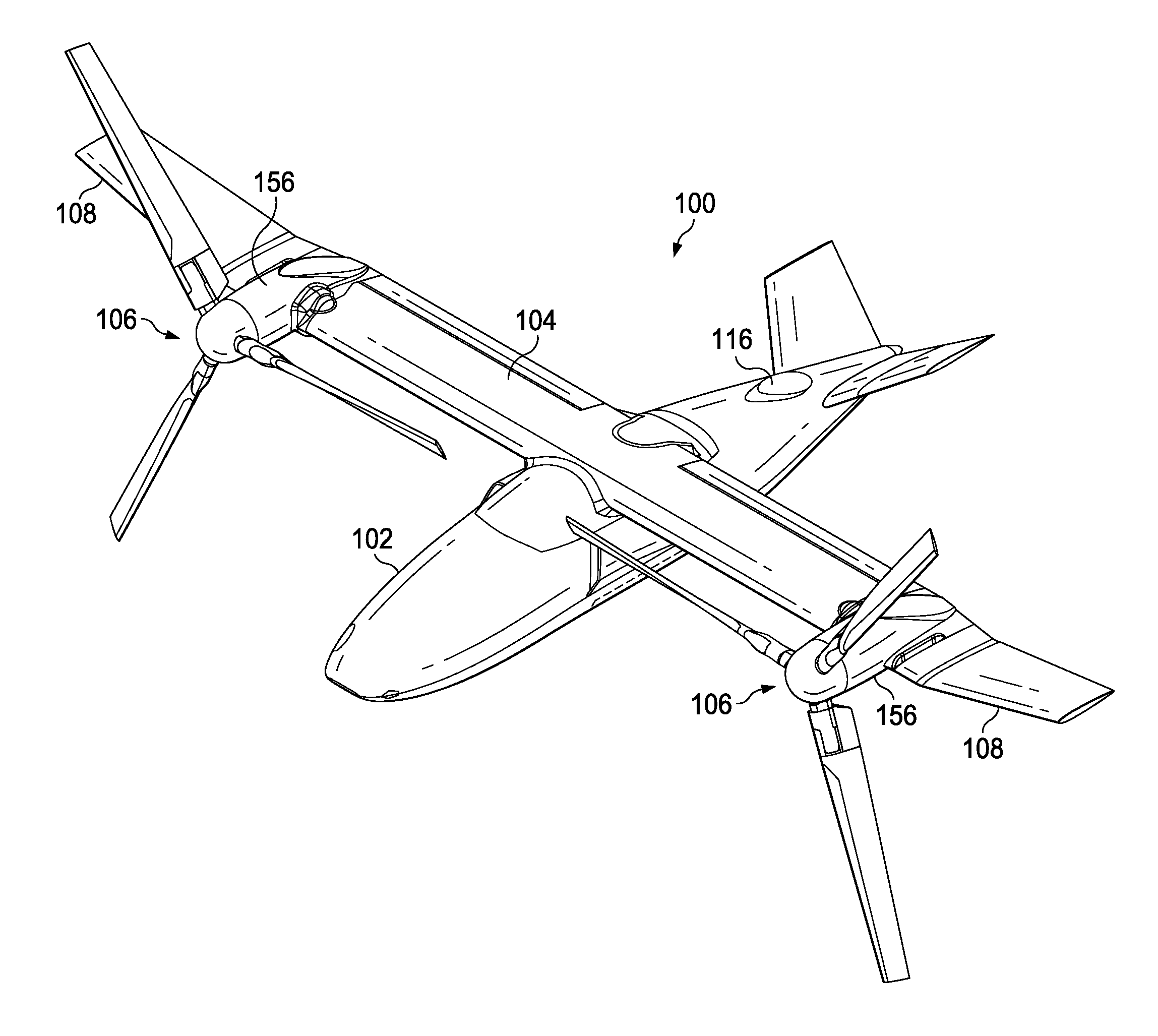
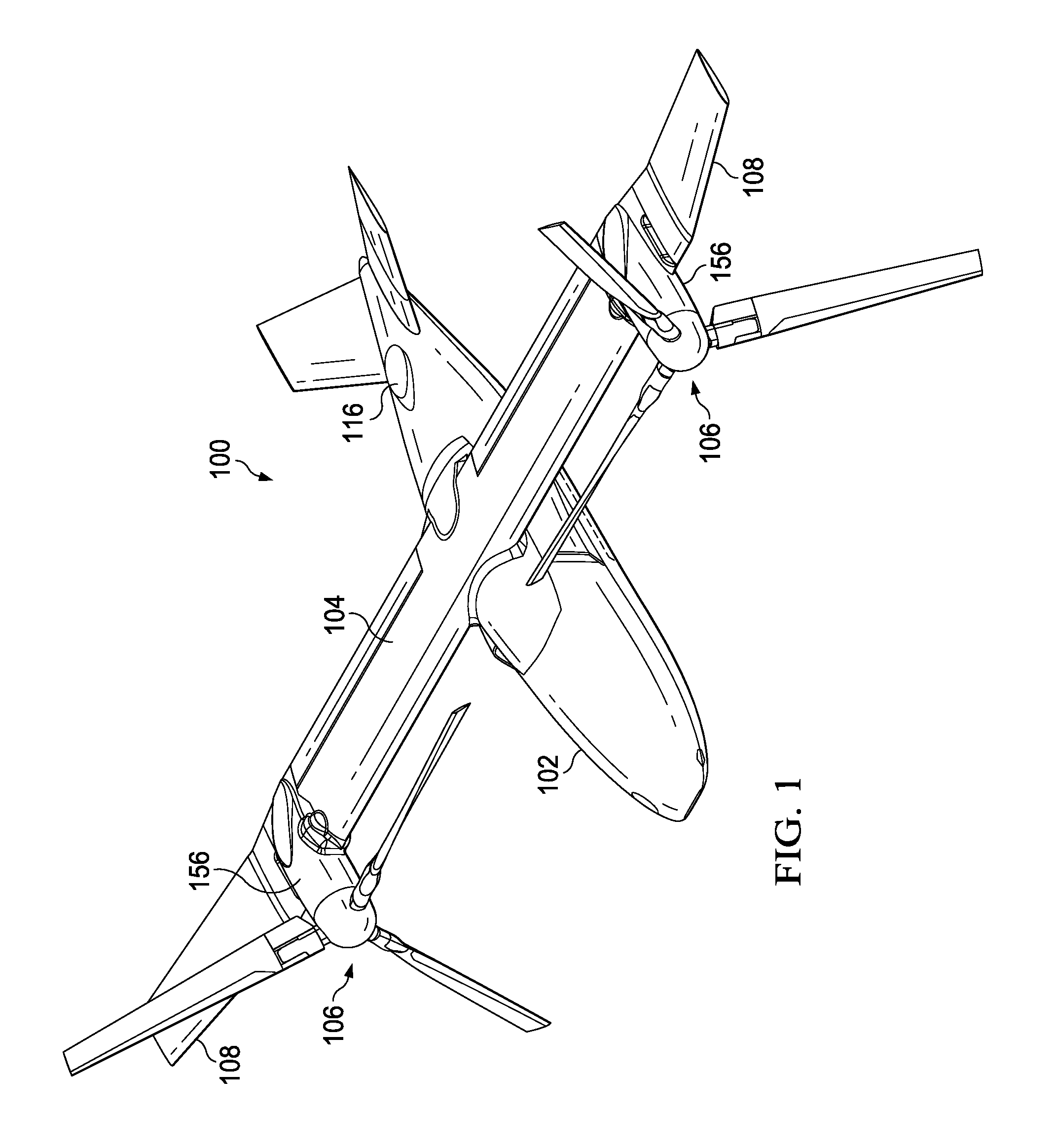
FIG. 1 is an oblique top right view of an aircraft according to the disclosure with the aircraft in a cruise configuration.
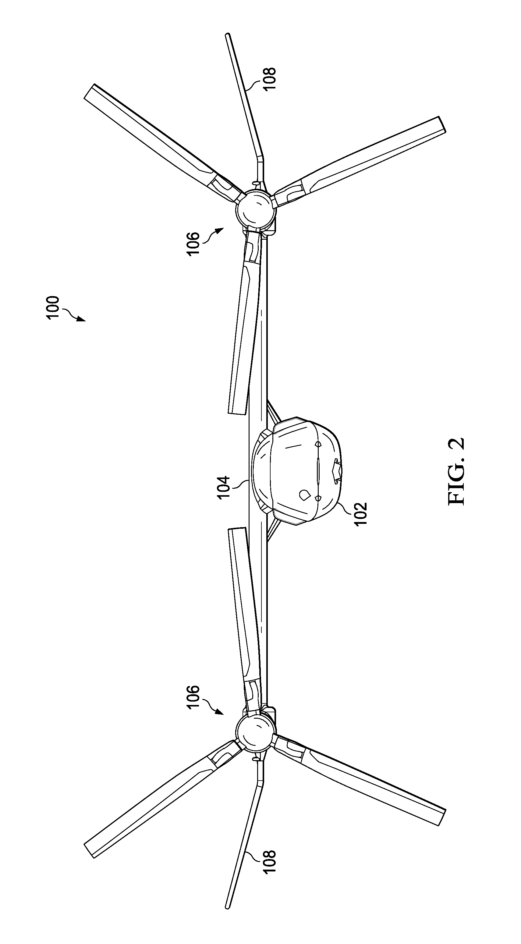
FIG. 2 is a front view of the aircraft of FIG. 1 in a cruise configuration.
FIG. 3 is an oblique top right view of the aircraft of FIG. 1 with the aircraft in a vertical takeoff and landing (VTOL) configuration.
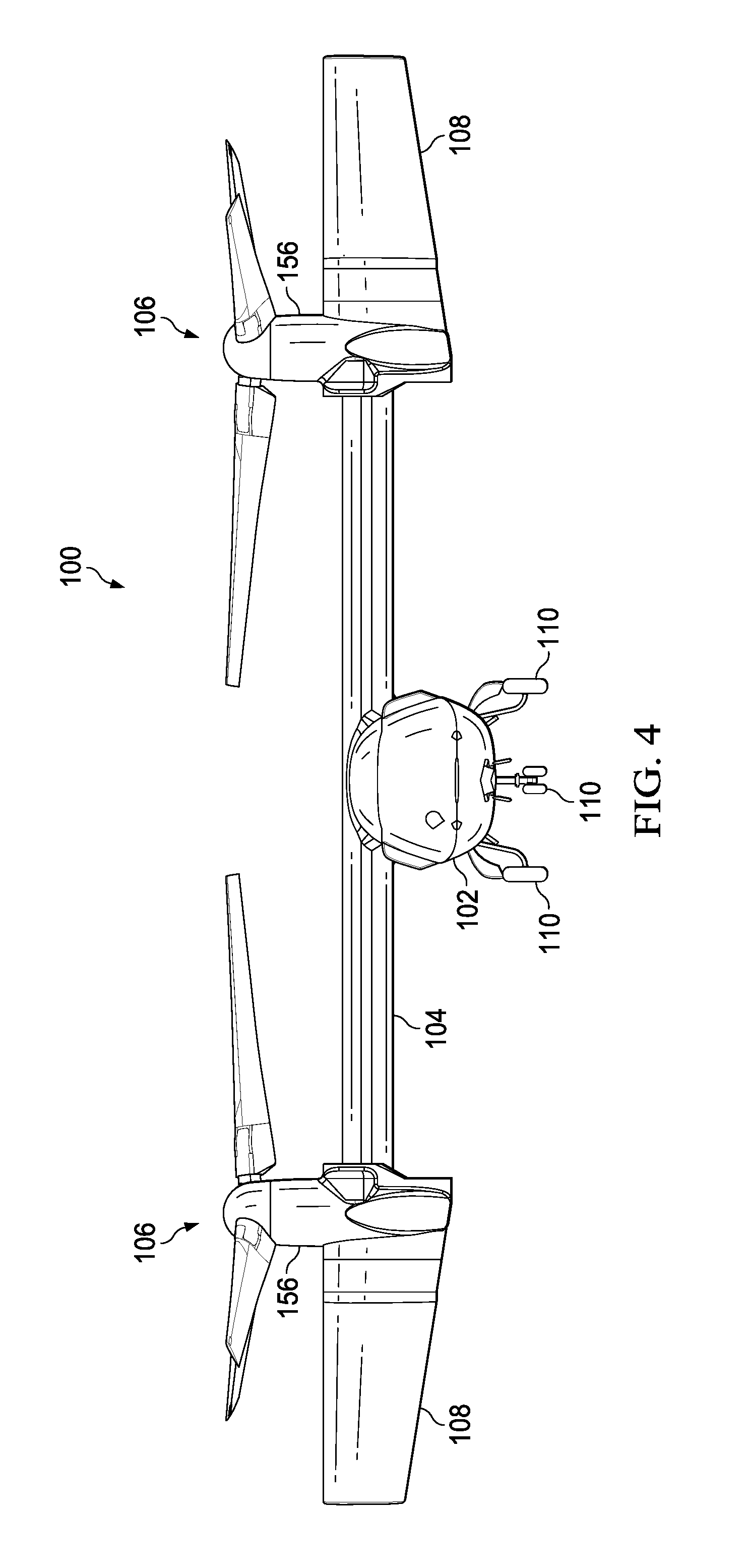
FIG. 4 is a front view of the aircraft of FIG. 1 with the aircraft in a VTOL configuration.
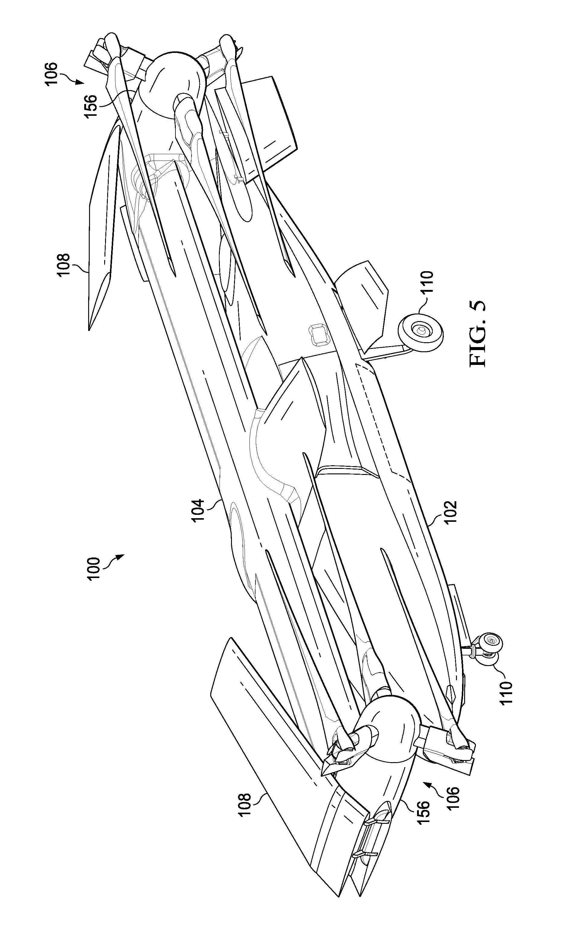
FIG. 5 is an oblique top right view of the aircraft of FIG. 1 with the aircraft in a folded configuration.
FIG. 6 is a front view of the aircraft of FIG. 1 with the aircraft in a folded configuration.
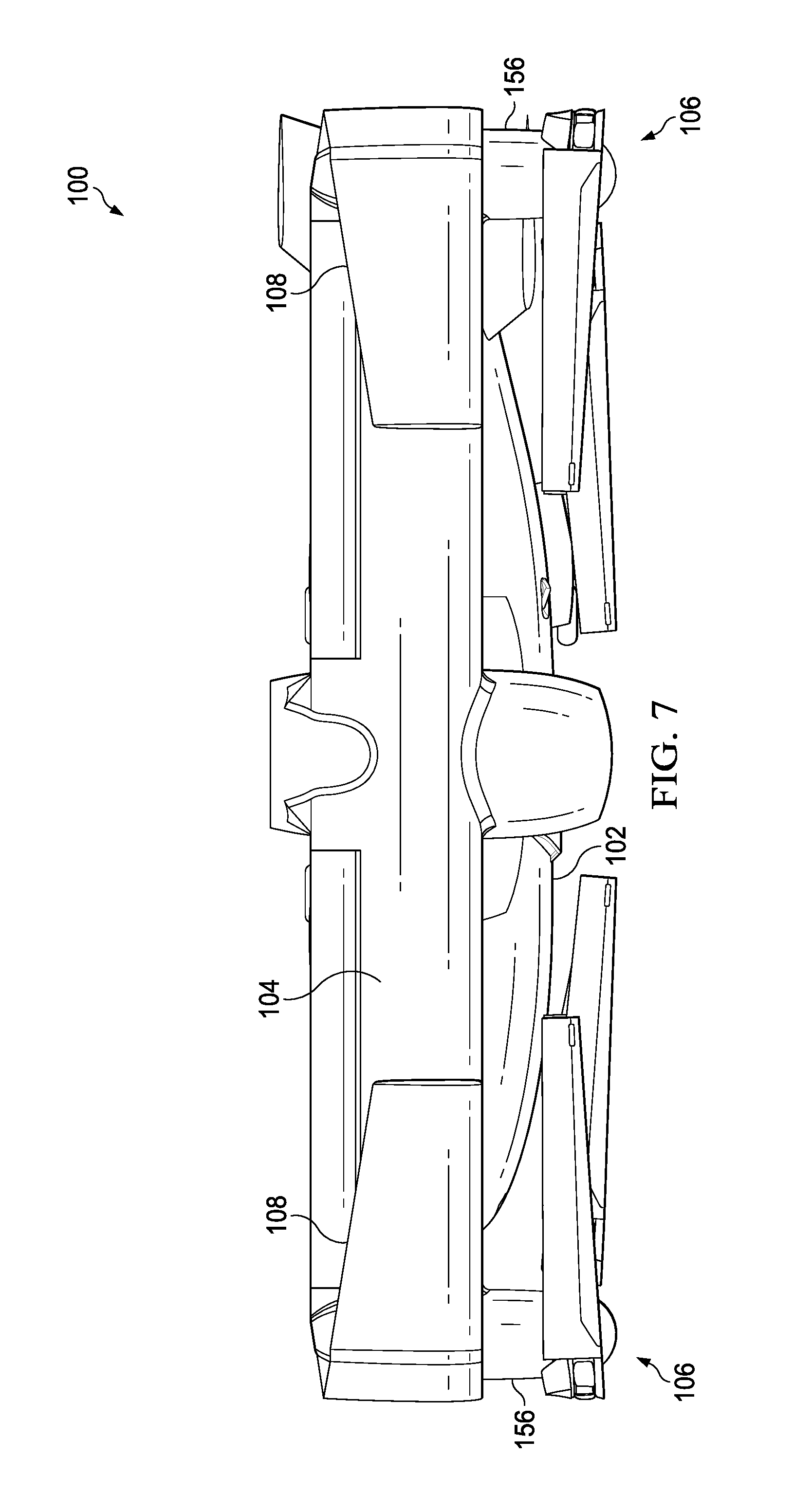
FIG. 7 is a top view of the aircraft of FIG. 1 with the aircraft in a folded configuration.
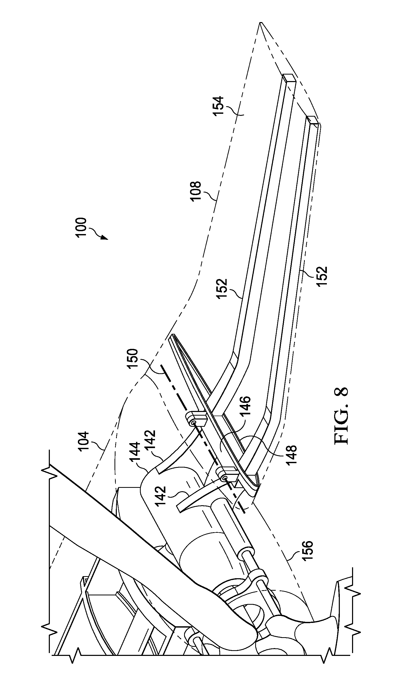
FIG. 8 is an oblique view of a wing extension of the aircraft of FIG. 1 with the wing extension in a deployed configuration.
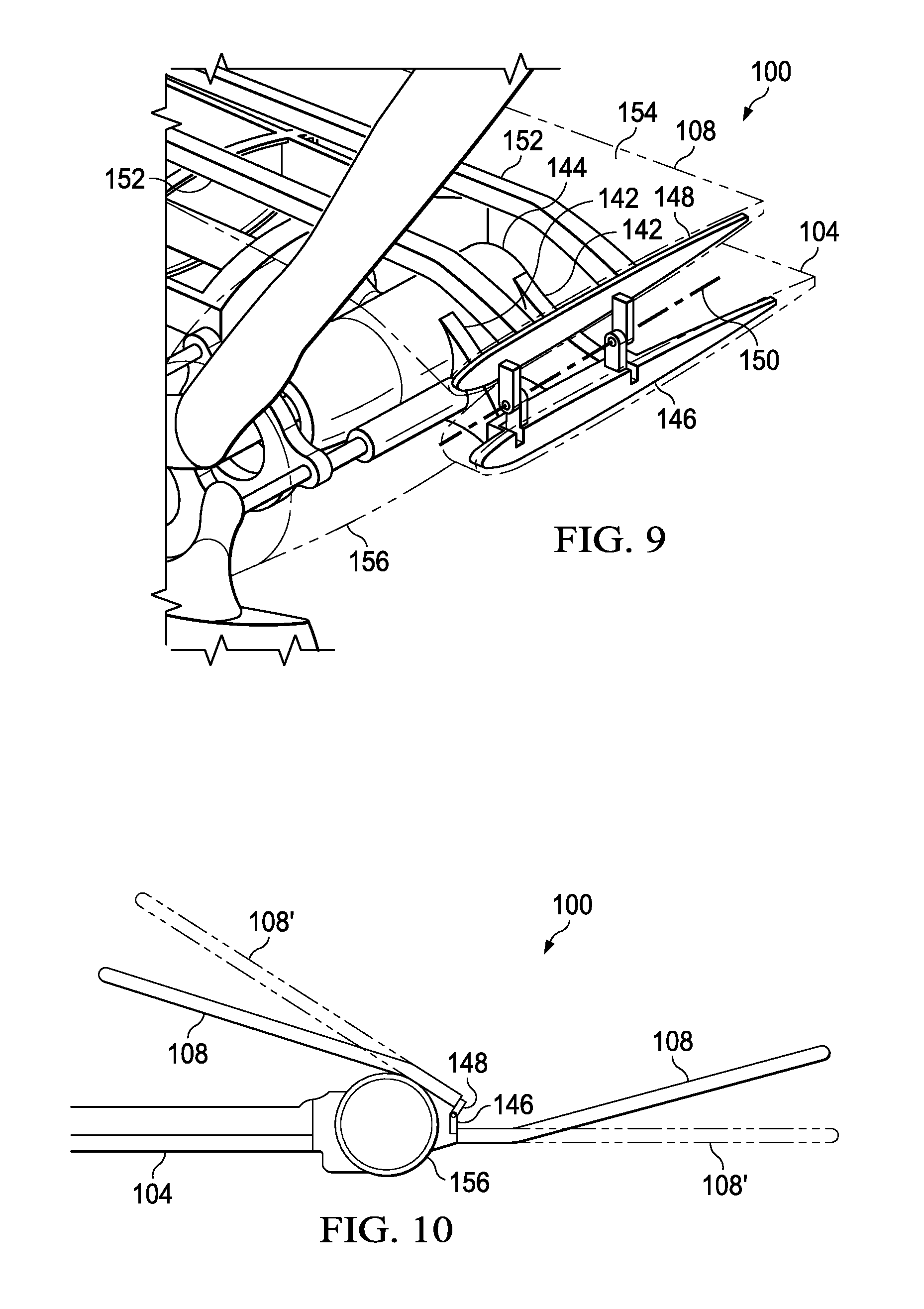
FIG. 9 is a partial oblique view of the wing extension of FIG. 8 with the wing extension in a folded configuration.
FIG. 10 is a schematic diagram comparing the locations of the wing extension of FIG. 8 in a folded configuration and in a deployed configuration.
DETAILED DESCRIPTION
In the specification, reference may be made to the spatial relationships between various components and to the spatial orientation of various aspects of components as the devices are depicted in the attached drawings. However, as will be recognized by those skilled in the art after a complete reading of the present disclosure, the devices, members, apparatuses, etc. described herein may be positioned in any desired orientation. Thus, the use of terms such as "above," "below," "upper," "lower," or other like terms to describe a spatial relationship between various components or to describe the spatial orientation of aspects of such components should be understood to describe a relative relationship between the components or a spatial orientation of aspects of such components, respectively, as the device described herein may be oriented in any desired direction.
Referring to FIGS. 1-7 in the drawings, an aircraft 100 is illustrated. The aircraft 100 comprises a tiltrotor unmanned aerial vehicle (UAV). The aircraft 100 comprises a fuselage 102, a wing 104, rotor systems 106, foldable wing extensions 108, and landing gear 110. The aircraft 100 is generally operable in a cruise mode as shown in FIGS. 1 and 2 in which the aircraft 100 orients the rotor systems 106 and wing extensions 108 to allow flight in a manner substantially similar to a fixed wing aircraft. The aircraft 100 is also operable in a vertical takeoff and landing (VTOL) mode as shown in FIGS. 3 and 4 in which the aircraft 100 orients the rotor systems 106 and wing extensions 108 to allow vertical takeoff and landing in a manner substantially similar to a helicopter. In this embodiment, the aircraft 100 can also operate in a transition mode in which the rotors systems 106 and wing extensions 108 are oriented in positions between the positions shown in the cruise mode and the VTOL mode.
Referring now to FIGS. 8-10, the wing extension 108 is shown in greater detail. Most generally, the wing extension 108 comprises at least one mount 142 connected to a proprotor gearbox 144 associated with a rotor system 106, a first hinge portion 146 connected to the mounts 142, and a second hinge portion 148 movably connected to the first hinge portion 146 about a hinge axis 150. The wing extension 108 further comprises one or more struts 152 connected to the second hinge portion 148. The struts 152 generally provide structural support for a skin 154 of the wing extension 108. With reference to FIG. 10, while the wing extension 108 comprises a dihedral configuration, in alternative embodiments, a wing extension 108' may comprise a straight configuration. As shown, in this embodiment, the dihedral shape of the wing extension 108 allows the wing extension to stow in a folded position so that the wing extension 108 can contact a pylon 156 carried by the wing 104 or other outer portion of wing 104 while fitting into a relatively smaller vertical and lateral envelope of space as compared to the straight wing extension 108'.
In some embodiments, the wing extensions 108 are provided to increase cruise efficiency without increasing rotor download excessively in hover, while still allowing the aircraft 100 the ability to fold and fit into confined spaces. The wing extensions 108 are generally horizontal when the aircraft 100 is in a cruise configuration. Because the wing extensions 108 are generally vertical in hover or VTOL configurations, the wing extensions 108 are generally streamline with the rotor system 106 thrust direction. The wing extension 108 does not attach directly to structural components of the wing 104, but rather, attach to components carried in the rotatable pylon 156. In alternative embodiments, wing extensions can comprise straight or anhedral shapes suitable for improved stowing. Further, in alternative embodiments, with differently shaped pylons 156 or other structures, the wing extensions can be shaped to complement the differently shaped pylons and/or structures so that the wing extensions nest against or otherwise abut the pylons and/or other structures in a space efficient manner when folded. In some embodiments, manual pinning and folding/unfolding of the wing extensions 108 can be utilized. However, in alternative embodiments, automated and/or automatic locking/unlocking and folding/unfolding may be utilized. Further, while the wing extensions 108 are shown as folding upward and over the pylon 156, in alternative embodiments, wing extensions can be configured to fold down and/or under the pylon.
At least one embodiment is disclosed and variations, combinations, and/or modifications of the embodiment(s) and/or features of the embodiment(s) made by a person having ordinary skill in the art are within the scope of the disclosure. Alternative embodiments that result from combining, integrating, and/or omitting features of the embodiment(s) are also within the scope of the disclosure. Where numerical ranges or limitations are expressly stated, such express ranges or limitations should be understood to include iterative ranges or limitations of like magnitude falling within the expressly stated ranges or limitations (e.g., from about 1 to about 10 includes, 2, 3, 4, etc.; greater than 0.10 includes 0.11, 0.12, 0.13, etc.). For example, whenever a numerical range with a lower limit, R.sub.l, and an upper limit, R.sub.u, is disclosed, any number falling within the range is specifically disclosed. In particular, the following numbers within the range are specifically disclosed: R=R.sub.l+k*(R.sub.u-R.sub.l), wherein k is a variable ranging from 1 percent to 100 percent with a 1 percent increment, i.e., k is 1 percent, 2 percent, 3 percent, 4 percent, 5 percent, . . . 50 percent, 51 percent, 52 percent, . . . , 95 percent, 96 percent, 97 percent, 98 percent, 99 percent, or 100 percent. Moreover, any numerical range defined by two R numbers as defined in the above is also specifically disclosed. Use of the term "optionally" with respect to any element of a claim means that the element is required, or alternatively, the element is not required, both alternatives being within the scope of the claim. Use of broader terms such as comprises, includes, and having should be understood to provide support for narrower terms such as consisting of, consisting essentially of, and comprised substantially of. Accordingly, the scope of protection is not limited by the description set out above but is defined by the claims that follow, that scope including all equivalents of the subject matter of the claims. Each and every claim is incorporated as further disclosure into the specification and the claims are embodiment(s) of the present invention.
* * * * *
D00000
D00001
D00002
D00003
D00004
D00005
D00006
D00007
D00008
D00009
XML
uspto.report is an independent third-party trademark research tool that is not affiliated, endorsed, or sponsored by the United States Patent and Trademark Office (USPTO) or any other governmental organization. The information provided by uspto.report is based on publicly available data at the time of writing and is intended for informational purposes only.
While we strive to provide accurate and up-to-date information, we do not guarantee the accuracy, completeness, reliability, or suitability of the information displayed on this site. The use of this site is at your own risk. Any reliance you place on such information is therefore strictly at your own risk.
All official trademark data, including owner information, should be verified by visiting the official USPTO website at www.uspto.gov. This site is not intended to replace professional legal advice and should not be used as a substitute for consulting with a legal professional who is knowledgeable about trademark law.