Enabling planned upgrade/downgrade of network devices without impacting network sessions
Golshan , et al. Sept
U.S. patent number 10,411,956 [Application Number 16/125,078] was granted by the patent office on 2019-09-10 for enabling planned upgrade/downgrade of network devices without impacting network sessions. This patent grant is currently assigned to A10 Networks, Inc.. The grantee listed for this patent is A10 NETWORKS, INC.. Invention is credited to Ali Golshan, Venky Natham, Swaminathan Sankar.


| United States Patent | 10,411,956 |
| Golshan , et al. | September 10, 2019 |
Enabling planned upgrade/downgrade of network devices without impacting network sessions
Abstract
Provided are methods and systems for enabling a planned upgrade or a planned downgrade of a first network device. A method may commence with receiving a request for a virtual service via a Transmission Control Protocol (TCP) session between the first network device and the client device. The method may further include creating, by a second network device being a standby device for the first network device, a redirect network session for the TCP session. The method may continue with delivering, by the first network device, the request for the virtual service to a server. Upon a change designating the second network device as an active device for the virtual service, the second network device may receive, from the server, a server response associated with the virtual service and redirect the server response to the first network device for further sending of the server response to the client device.
| Inventors: | Golshan; Ali (Palo Alto, CA), Sankar; Swaminathan (San Jose, CA), Natham; Venky (Fremont, CA) | ||||||||||
|---|---|---|---|---|---|---|---|---|---|---|---|
| Applicant: |
|
||||||||||
| Assignee: | A10 Networks, Inc. (San Jose,
CA) |
||||||||||
| Family ID: | 54332980 | ||||||||||
| Appl. No.: | 16/125,078 | ||||||||||
| Filed: | September 7, 2018 |
Prior Publication Data
| Document Identifier | Publication Date | |
|---|---|---|
| US 20190020536 A1 | Jan 17, 2019 | |
Related U.S. Patent Documents
| Application Number | Filing Date | Patent Number | Issue Date | ||
|---|---|---|---|---|---|
| 15798236 | Oct 30, 2017 | 10110429 | |||
| 14261310 | Oct 31, 2017 | 9806943 | |||
| Current U.S. Class: | 1/1 |
| Current CPC Class: | H04L 67/1023 (20130101); H04L 67/34 (20130101); H04L 67/148 (20130101); H04L 41/0803 (20130101); H04L 67/145 (20130101); H04L 67/1027 (20130101) |
| Current International Class: | H04L 12/24 (20060101); H04L 29/08 (20060101) |
References Cited [Referenced By]
U.S. Patent Documents
| 4720850 | January 1988 | Oberlander et al. |
| 4864492 | September 1989 | Blakely-Fogel et al. |
| 4882699 | November 1989 | Evensen |
| 5218676 | June 1993 | Ben-Ayed et al. |
| 5293488 | March 1994 | Riley et al. |
| 5432908 | July 1995 | Heddes et al. |
| 5774660 | June 1998 | Brendel et al. |
| 5781550 | July 1998 | Templin et al. |
| 5862339 | January 1999 | Bonnaure et al. |
| 5875185 | February 1999 | Wang et al. |
| 5931914 | August 1999 | Chiu |
| 5958053 | September 1999 | Denker |
| 6003069 | December 1999 | Cavill |
| 6047268 | April 2000 | Bartoli et al. |
| 6075783 | June 2000 | Voit |
| 6131163 | October 2000 | Wiegel |
| 6141749 | October 2000 | Coss et al. |
| 6167428 | December 2000 | Ellis |
| 6321338 | November 2001 | Porras et al. |
| 6324286 | November 2001 | Lai et al. |
| 6360265 | March 2002 | Falck et al. |
| 6363075 | March 2002 | Huang et al. |
| 6374300 | April 2002 | Masters |
| 6389462 | May 2002 | Cohen et al. |
| 6415329 | July 2002 | Gelman et al. |
| 6456617 | September 2002 | Oda et al. |
| 6483600 | November 2002 | Schuster et al. |
| 6519243 | February 2003 | Nonaka et al. |
| 6535516 | March 2003 | Leu et al. |
| 6578066 | June 2003 | Logan et al. |
| 6587866 | July 2003 | Modi et al. |
| 6600738 | July 2003 | Alperovich et al. |
| 6658114 | December 2003 | Farn et al. |
| 6772205 | August 2004 | Lavian et al. |
| 6772334 | August 2004 | Glawitsch |
| 6779033 | August 2004 | Watson et al. |
| 6804224 | October 2004 | Schuster et al. |
| 6832322 | December 2004 | Boden et al. |
| 7010605 | March 2006 | Dharmarajan |
| 7013338 | March 2006 | Nag et al. |
| 7058718 | June 2006 | Fontes et al. |
| 7058789 | June 2006 | Henderson et al. |
| 7058973 | June 2006 | Sultan |
| 7069438 | June 2006 | Balabine et al. |
| 7086086 | August 2006 | Ellis |
| 7111162 | September 2006 | Bagepalli et al. |
| 7143087 | November 2006 | Fairweather |
| 7167927 | January 2007 | Philbrick et al. |
| 7181524 | February 2007 | Lele |
| 7228359 | June 2007 | Monteiro |
| 7254133 | August 2007 | Govindarajan et al. |
| 7266604 | September 2007 | Nathan et al. |
| 7269850 | September 2007 | Govindarajan et al. |
| 7284272 | October 2007 | Howard et al. |
| 7290050 | October 2007 | Smith et al. |
| 7301899 | November 2007 | Goldstone |
| 7308710 | December 2007 | Yarborough |
| 7310686 | December 2007 | Uysal |
| 7328267 | February 2008 | Bashyam et al. |
| 7337241 | February 2008 | Boucher et al. |
| 7343399 | March 2008 | Hayball et al. |
| 7370100 | May 2008 | Gunturu |
| 7370353 | May 2008 | Yang |
| 7373500 | May 2008 | Ramelson et al. |
| 7391725 | June 2008 | Huitema et al. |
| 7398317 | July 2008 | Chen et al. |
| 7406709 | July 2008 | Maher, III et al. |
| 7423977 | September 2008 | Joshi |
| 7430755 | September 2008 | Hughes et al. |
| 7441270 | October 2008 | Edwards et al. |
| 7451312 | November 2008 | Medvinsky et al. |
| 7467202 | December 2008 | Savchuk |
| 7506360 | March 2009 | Wilkinson et al. |
| 7512980 | March 2009 | Copeland et al. |
| 7516485 | April 2009 | Lee et al. |
| 7529242 | May 2009 | Lyle |
| 7552323 | June 2009 | Shay |
| 7568041 | July 2009 | Turner et al. |
| 7583668 | September 2009 | Mayes et al. |
| 7584262 | September 2009 | Wang et al. |
| 7590736 | September 2009 | Hydrie et al. |
| 7591001 | September 2009 | Shay |
| 7603454 | October 2009 | Piper |
| 7610622 | October 2009 | Touitou et al. |
| 7613193 | November 2009 | Swami et al. |
| 7613822 | November 2009 | Joy et al. |
| 7673072 | March 2010 | Boucher et al. |
| 7675854 | March 2010 | Chen et al. |
| 7711790 | May 2010 | Barrett et al. |
| 7716369 | May 2010 | Le Pennec et al. |
| 7733866 | June 2010 | Mishra et al. |
| 7747748 | June 2010 | Allen |
| 7779130 | August 2010 | Toutonghi |
| 7826487 | November 2010 | Mukerji et al. |
| 7908651 | March 2011 | Maher |
| 7948952 | May 2011 | Hurtta et al. |
| 7965727 | June 2011 | Sakata et al. |
| 7979694 | July 2011 | Touitou et al. |
| 7990847 | August 2011 | Leroy et al. |
| 7992201 | August 2011 | Aldridge et al. |
| 8079077 | December 2011 | Chen et al. |
| 8081640 | December 2011 | Ozawa et al. |
| 8090866 | January 2012 | Bashyam et al. |
| 8099492 | January 2012 | Dahlin et al. |
| 8116312 | February 2012 | Riddoch et al. |
| 8122116 | February 2012 | Matsunaga et al. |
| 8151019 | April 2012 | Le et al. |
| 8185651 | May 2012 | Moran et al. |
| 8244876 | August 2012 | Sollee |
| 8255644 | August 2012 | Sonnier et al. |
| 8261339 | September 2012 | Aldridge et al. |
| 8291487 | October 2012 | Chen et al. |
| 8327128 | December 2012 | Prince et al. |
| 8332925 | December 2012 | Chen et al. |
| 8347392 | January 2013 | Chess et al. |
| 8379515 | February 2013 | Mukerji |
| 8387128 | February 2013 | Chen et al. |
| 8464333 | June 2013 | Chen et al. |
| 8520615 | August 2013 | Mehta et al. |
| 8559437 | October 2013 | Mishra et al. |
| 8560693 | October 2013 | Wang et al. |
| 8595383 | November 2013 | Wang et al. |
| 8595819 | November 2013 | Chen et al. |
| RE44701 | January 2014 | Chen et al. |
| 8675488 | March 2014 | Sidebottom et al. |
| 8681610 | March 2014 | Mukerji |
| 8782221 | July 2014 | Han |
| 8904512 | December 2014 | Chen et al. |
| 8914871 | December 2014 | Chen et al. |
| 8918857 | December 2014 | Chen et al. |
| RE45347 | January 2015 | Chun et al. |
| 8943577 | January 2015 | Chen et al. |
| 8977749 | March 2015 | Han |
| 8996670 | March 2015 | Kupinsky et al. |
| 9032502 | May 2015 | Chen et al. |
| 9094364 | July 2015 | Jalan et al. |
| 9106561 | August 2015 | Jalan et al. |
| 9118618 | August 2015 | Davis |
| 9118620 | August 2015 | Davis |
| 9124550 | September 2015 | Chen et al. |
| 9137301 | September 2015 | Dunlap et al. |
| 9154584 | October 2015 | Han |
| 9258332 | February 2016 | Chen et al. |
| 9344456 | May 2016 | Chen et al. |
| 9386088 | July 2016 | Zheng et al. |
| 9531846 | December 2016 | Han et al. |
| 9596286 | March 2017 | Kamat et al. |
| 9602442 | March 2017 | Han |
| 9742879 | August 2017 | Davis |
| 9806943 | October 2017 | Golshan et al. |
| 2001/0015812 | August 2001 | Sugaya |
| 2001/0023442 | September 2001 | Masters |
| 2001/0042200 | November 2001 | Lamberton et al. |
| 2002/0026515 | February 2002 | Michielsens et al. |
| 2002/0026531 | February 2002 | Keane et al. |
| 2002/0032799 | March 2002 | Wiedeman et al. |
| 2002/0046348 | April 2002 | Brustoloni |
| 2002/0053031 | May 2002 | Bendinelli et al. |
| 2002/0078164 | June 2002 | Reinschmidt |
| 2002/0091844 | July 2002 | Craft et al. |
| 2002/0103916 | August 2002 | Chen et al. |
| 2002/0138618 | September 2002 | Szabo |
| 2002/0141386 | October 2002 | Minert et al. |
| 2002/0141448 | October 2002 | Matsunaga |
| 2002/0143955 | October 2002 | Shimada et al. |
| 2002/0143991 | October 2002 | Chow et al. |
| 2002/0188678 | December 2002 | Edecker et al. |
| 2003/0009591 | January 2003 | Hayball et al. |
| 2003/0035409 | February 2003 | Wang et al. |
| 2003/0061506 | March 2003 | Cooper et al. |
| 2003/0065950 | April 2003 | Yarborough |
| 2003/0081624 | May 2003 | Aggarwal et al. |
| 2003/0088788 | May 2003 | Yang |
| 2003/0101113 | May 2003 | Dang |
| 2003/0135625 | July 2003 | Fontes et al. |
| 2003/0135653 | July 2003 | Marovich |
| 2003/0152078 | August 2003 | Henderson et al. |
| 2003/0167340 | September 2003 | Jonsson |
| 2003/0229809 | December 2003 | Wexler et al. |
| 2004/0010545 | January 2004 | Pandya |
| 2004/0054920 | March 2004 | Wilson et al. |
| 2004/0062246 | April 2004 | Boucher et al. |
| 2004/0073703 | April 2004 | Boucher et al. |
| 2004/0078419 | April 2004 | Ferrari et al. |
| 2004/0078480 | April 2004 | Boucher et al. |
| 2004/0103315 | May 2004 | Cooper et al. |
| 2004/0107360 | June 2004 | Herrmann et al. |
| 2004/0184442 | September 2004 | Jones et al. |
| 2004/0243718 | December 2004 | Fujiyoshi |
| 2004/0250059 | December 2004 | Ramelson |
| 2005/0005207 | January 2005 | Herneque |
| 2005/0027947 | February 2005 | Landin |
| 2005/0033985 | February 2005 | Xu et al. |
| 2005/0036511 | February 2005 | Baratakke et al. |
| 2005/0038898 | February 2005 | Mittig et al. |
| 2005/0039033 | February 2005 | Meyers et al. |
| 2005/0050364 | March 2005 | Feng |
| 2005/0074001 | April 2005 | Mattes et al. |
| 2005/0080890 | April 2005 | Yang et al. |
| 2005/0114492 | May 2005 | Arberg et al. |
| 2005/0135422 | June 2005 | Yeh |
| 2005/0144468 | June 2005 | Northcutt et al. |
| 2005/0163073 | July 2005 | Heller et al. |
| 2005/0169285 | August 2005 | Wills et al. |
| 2005/0198335 | September 2005 | Brown et al. |
| 2005/0213586 | September 2005 | Cyganski et al. |
| 2005/0240989 | October 2005 | Kim et al. |
| 2005/0251856 | November 2005 | Araujo et al. |
| 2005/0281190 | December 2005 | McGee et al. |
| 2006/0023721 | February 2006 | Miyake et al. |
| 2006/0031506 | February 2006 | Redgate |
| 2006/0036610 | February 2006 | Wang |
| 2006/0041745 | February 2006 | Pames |
| 2006/0062142 | March 2006 | Appanna et al. |
| 2006/0063517 | March 2006 | Oh et al. |
| 2006/0064440 | March 2006 | Perry |
| 2006/0069804 | March 2006 | Miyake et al. |
| 2006/0080446 | April 2006 | Bahl |
| 2006/0126625 | June 2006 | Schollmeier et al. |
| 2006/0164978 | July 2006 | Werner et al. |
| 2006/0168319 | July 2006 | Trossen |
| 2006/0195698 | August 2006 | Pinkerton et al. |
| 2006/0227771 | October 2006 | Raghunath et al. |
| 2006/0230129 | October 2006 | Swami et al. |
| 2006/0233100 | October 2006 | Luft et al. |
| 2006/0280121 | December 2006 | Matoba |
| 2007/0002857 | January 2007 | Maher |
| 2007/0011419 | January 2007 | Conti |
| 2007/0019543 | January 2007 | Wei et al. |
| 2007/0022479 | January 2007 | Sikdar et al. |
| 2007/0076653 | April 2007 | Park et al. |
| 2007/0124487 | May 2007 | Yoshimoto et al. |
| 2007/0124502 | May 2007 | Li |
| 2007/0165622 | July 2007 | O'Rourke et al. |
| 2007/0177506 | August 2007 | Singer et al. |
| 2007/0180119 | August 2007 | Khivesara et al. |
| 2007/0180226 | August 2007 | Schory et al. |
| 2007/0180513 | August 2007 | Raz et al. |
| 2007/0185998 | August 2007 | Touitou et al. |
| 2007/0230337 | October 2007 | Igarashi et al. |
| 2007/0242738 | October 2007 | Park et al. |
| 2007/0243879 | October 2007 | Park et al. |
| 2007/0245090 | October 2007 | King et al. |
| 2007/0248009 | October 2007 | Petersen |
| 2007/0294694 | December 2007 | Jeter et al. |
| 2008/0016161 | January 2008 | Tsirtsis et al. |
| 2008/0031263 | February 2008 | Ervin et al. |
| 2008/0034111 | February 2008 | Kamath et al. |
| 2008/0034419 | February 2008 | Mullick et al. |
| 2008/0076432 | March 2008 | Senarath et al. |
| 2008/0120129 | May 2008 | Seubert et al. |
| 2008/0216177 | September 2008 | Yokosato et al. |
| 2008/0225722 | September 2008 | Khemani et al. |
| 2008/0253390 | October 2008 | Das et al. |
| 2008/0289044 | November 2008 | Choi |
| 2008/0291911 | November 2008 | Lee et al. |
| 2008/0298303 | December 2008 | Tsirtsis |
| 2009/0024722 | January 2009 | Sethuraman et al. |
| 2009/0031415 | January 2009 | Aldridge et al. |
| 2009/0077651 | March 2009 | Poeluev |
| 2009/0092124 | April 2009 | Singhal et al. |
| 2009/0113536 | April 2009 | Zhang et al. |
| 2009/0138606 | May 2009 | Moran et al. |
| 2009/0138945 | May 2009 | Savchuk |
| 2009/0164614 | June 2009 | Christian et al. |
| 2009/0210698 | August 2009 | Candelore |
| 2009/0285196 | November 2009 | Lee et al. |
| 2009/0288134 | November 2009 | Foottit et al. |
| 2010/0042869 | February 2010 | Szabo et al. |
| 2010/0054139 | March 2010 | Chun et al. |
| 2010/0061319 | March 2010 | Aso et al. |
| 2010/0064008 | March 2010 | Yan et al. |
| 2010/0095018 | April 2010 | Khemani et al. |
| 2010/0106854 | April 2010 | Kim et al. |
| 2010/0205310 | August 2010 | Altshuler et al. |
| 2010/0228819 | September 2010 | Wei |
| 2010/0235522 | September 2010 | Chen et al. |
| 2010/0238828 | September 2010 | Russell |
| 2010/0257278 | October 2010 | Gunturu |
| 2010/0262819 | October 2010 | Yang et al. |
| 2010/0265824 | October 2010 | Chao et al. |
| 2010/0268814 | October 2010 | Cross et al. |
| 2010/0318631 | December 2010 | Shukla |
| 2010/0322252 | December 2010 | Suganthi et al. |
| 2010/0333101 | December 2010 | Pope et al. |
| 2010/0333209 | December 2010 | Alve |
| 2011/0007652 | January 2011 | Bai |
| 2011/0032941 | February 2011 | Quach et al. |
| 2011/0060831 | March 2011 | Ishii et al. |
| 2011/0083174 | April 2011 | Aldridge et al. |
| 2011/0093522 | April 2011 | Chen et al. |
| 2011/0099623 | April 2011 | Garrard et al. |
| 2011/0149879 | June 2011 | Noriega et al. |
| 2011/0209157 | August 2011 | Sumida et al. |
| 2011/0276982 | November 2011 | Nakayama et al. |
| 2011/0302256 | December 2011 | Sureshehandra et al. |
| 2011/0307606 | December 2011 | Cobb |
| 2012/0008495 | January 2012 | Shen et al. |
| 2012/0026897 | February 2012 | Guichard et al. |
| 2012/0039175 | February 2012 | Sridhar et al. |
| 2012/0117382 | May 2012 | Larson et al. |
| 2012/0155495 | June 2012 | Clee et al. |
| 2012/0173759 | July 2012 | Agarwal et al. |
| 2012/0215910 | August 2012 | Wada |
| 2012/0290727 | November 2012 | Tivig |
| 2013/0089099 | April 2013 | Pollock et al. |
| 2013/0135996 | May 2013 | Torres et al. |
| 2013/0176854 | July 2013 | Chisu et al. |
| 2013/0176908 | July 2013 | Baniel et al. |
| 2013/0191486 | July 2013 | Someya et al. |
| 2013/0191548 | July 2013 | Boddukuri et al. |
| 2013/0212242 | August 2013 | Mendiratta et al. |
| 2013/0227165 | August 2013 | Liu |
| 2013/0250765 | September 2013 | Ehsan et al. |
| 2013/0258846 | October 2013 | Damola |
| 2013/0311686 | November 2013 | Fetterman et al. |
| 2014/0038163 | February 2014 | Karpoff |
| 2014/0058938 | February 2014 | McClung, III |
| 2014/0086052 | March 2014 | Cai et al. |
| 2014/0254367 | September 2014 | Jeong et al. |
| 2014/0258536 | September 2014 | Chiong |
| 2014/0286313 | September 2014 | Fu et al. |
| 2014/0359052 | December 2014 | Joachimpillai et al. |
| 2014/0359134 | December 2014 | Yoshida |
| 2015/0026794 | January 2015 | Zuk et al. |
| 2015/0156223 | June 2015 | Xu et al. |
| 2015/0237173 | August 2015 | Virkki et al. |
| 2015/0244566 | August 2015 | Puimedon |
| 2015/0296058 | October 2015 | Jalan et al. |
| 2015/0350048 | December 2015 | Sampat et al. |
| 2015/0350379 | December 2015 | Jalan et al. |
| 2016/0014126 | January 2016 | Jalan et al. |
| 2016/0162882 | June 2016 | McClung, III |
| 2017/0048107 | February 2017 | Dosovitsky et al. |
| 2017/0048356 | February 2017 | Thompson et al. |
| 2018/0069753 | March 2018 | Golshan et al. |
| 1372662 | Oct 2002 | CN | |||
| 1473300 | Feb 2004 | CN | |||
| 1529460 | Sep 2004 | CN | |||
| 1575582 | Feb 2005 | CN | |||
| 1910869 | Feb 2007 | CN | |||
| 1921457 | Feb 2007 | CN | |||
| 1937591 | Mar 2007 | CN | |||
| 101189598 | May 2008 | CN | |||
| 101442425 | May 2009 | CN | |||
| 101495993 | Jul 2009 | CN | |||
| 101682532 | Mar 2010 | CN | |||
| 101878663 | Nov 2010 | CN | |||
| 101495993 | Feb 2011 | CN | |||
| 102123156 | Jul 2011 | CN | |||
| 102577252 | Jul 2012 | CN | |||
| 103365654 | Oct 2013 | CN | |||
| 103428261 | Dec 2013 | CN | |||
| 103533018 | Jan 2014 | CN | |||
| 103944954 | Jul 2014 | CN | |||
| 104040990 | Sep 2014 | CN | |||
| 104137491 | Nov 2014 | CN | |||
| 104796396 | Jul 2015 | CN | |||
| 102577252 | Mar 2016 | CN | |||
| 1209876 | May 2002 | EP | |||
| 1482685 | Dec 2004 | EP | |||
| 1720287 | Nov 2006 | EP | |||
| 2057552 | May 2009 | EP | |||
| 2215863 | Aug 2010 | EP | |||
| 2296313 | Mar 2011 | EP | |||
| 2667571 | Nov 2013 | EP | |||
| 2760170 | Jul 2014 | EP | |||
| 2575328 | Nov 2014 | EP | |||
| 2760170 | Dec 2015 | EP | |||
| 1188498 | May 2014 | HK | |||
| 1189438 | Jun 2014 | HK | |||
| 1190539 | Jul 2014 | HK | |||
| 1182547 | Apr 2015 | HK | |||
| 1199153 | Jun 2015 | HK | |||
| 1199779 | Jul 2015 | HK | |||
| 1200617 | Aug 2015 | HK | |||
| 261CHE2014 | Jul 2016 | IN | |||
| 2000307634 | Nov 2000 | JP | |||
| 2004350188 | Dec 2004 | JP | |||
| 2005518595 | Jun 2005 | JP | |||
| 2006180295 | Jul 2006 | JP | |||
| 2006333245 | Dec 2006 | JP | |||
| 2007048052 | Feb 2007 | JP | |||
| 2011505752 | Feb 2011 | JP | |||
| 2013059122 | Mar 2013 | JP | |||
| 2013070423 | Apr 2013 | JP | |||
| 2013078134 | Apr 2013 | JP | |||
| 5364101 | Dec 2013 | JP | |||
| 5480959 | Apr 2014 | JP | |||
| 5579820 | Aug 2014 | JP | |||
| 5579821 | Aug 2014 | JP | |||
| 2014143686 | Aug 2014 | JP | |||
| 5906263 | Apr 2016 | JP | |||
| 20130096624 | Aug 2013 | KR | |||
| 101576585 | Dec 2015 | KR | |||
| 269763 | Feb 1996 | TW | |||
| 375721 | Dec 1999 | TW | |||
| 425821 | Mar 2001 | TW | |||
| 444478 | Jul 2001 | TW | |||
| WO2001013228 | Feb 2001 | WO | |||
| WO2001014990 | Mar 2001 | WO | |||
| WO2003073216 | Sep 2003 | WO | |||
| WO2003103233 | Dec 2003 | WO | |||
| WO2003103237 | Dec 2003 | WO | |||
| WO2006065691 | Jun 2006 | WO | |||
| WO2007076883 | Jul 2007 | WO | |||
| WO2008021620 | Feb 2008 | WO | |||
| WO2008053954 | May 2008 | WO | |||
| WO2009073295 | Jun 2009 | WO | |||
| WO2011049770 | Apr 2011 | WO | |||
| WO2011079381 | Jul 2011 | WO | |||
| WO2013081952 | Jun 2013 | WO | |||
| WO2013096019 | Jun 2013 | WO | |||
| WO2014031046 | Feb 2014 | WO | |||
| WO2014093829 | Jun 2014 | WO | |||
| WO2015164026 | Oct 2015 | WO | |||
Other References
|
Abe, et al., "Adaptive Split Connection Schemes in Advanced Relay Nodes," IEICE Technical Report, 2010, vol. 109 (438), pp. 25-30. cited by applicant . Cardellini, et al., "Dynamic Load Balancing on Web-Server Systems," IEEE Internet Computing, 1999, vol. 3 (3), pp. 28-39. cited by applicant . Chen, et al., "SSL/TLS-based Secure Tunnel Gateway System Design and Implementation," IEEE International Workshop on Anti-counterfeiting, Security, Identification, 2007, pp. 258-261. cited by applicant . Chiussi, et al., "A Network Architecture for MPLS-Based Micro-Mobility," IEEE WCNC, 2002, vol. 2, pp. 1-8. cited by applicant . Crotti, et al., "Detecting HTTP Tunnels with Statistical Mechanisms," IEEE International Conference on Communications, 2007, pp. 6162-6168. cited by applicant . EIGRP MPLS VPN PE-CE Site of Origin (SoO), Cisco, https://www.cisco.com/c/en/us/td/docs/ios/12_0s/feature/guide/s_mvesoo.ht- ml, 2006, pp. 14. cited by applicant . Enhanced Interior Gateway Routing Protocol, Cisco, Document ID 16406, 2005, https://www.cisco.com/c/en/us/support/docs/ip/enhanced-interior-gat- eway-routing-protocol-eigrp/16406-eigrp-toc.html, pp. 43. cited by applicant . FreeBSD, "tcp--TCP Protocol," Linux Programme.quadrature.s Manual [online], 2007, [retrieved on Apr. 13, 2016], Retreived from the Internet: <https://www.freebsd.org/cgi/man.cgi?query=tcp&apropos=0&sek- tion=7&manpath=SuSe+Linux%2Fi386+11.0&format=asci>. cited by applicant . Gite, "Linux Tune Network Stack (Buffers Size) to Increase Networking Performance," nixCraft [online], 2009, [retreived on Apr. 13, 2016], Retreived from the Internet: <URL:http://www.cyberciti.biz/faq/linux-tcp-tuning/>. cited by applicant . Goldszmidt, et al., "NetDispatcher: A TCP Connection Router," IBM Researc Report, RC 20853, 1997, pp. 1-31. cited by applicant . Haruyama, et al., "Dial-to-Connect VPN System for Remote DLNA Communication," IEEE Consumer Communications and Networking Conference, 2008, pp. 1224-1225. cited by applicant . Koike, et al., "Transport Middleware for Network-Based Control," IEICE Technical Report, 2000, vol. 100 (53), pp. 13-18. cited by applicant . Smith, et al., "Network Security Using NAT and NAPT," IEEE ICON, 2002, pp. 355-360. cited by applicant . Search Report and Written Opinion dated Jul. 6, 2015 for PCT Application No. PCT/US2015/022857. cited by applicant . Wang, et al., "Shield: Vulnerability-Driven Network Filters for Preventing Known Vulnerability Exploits," SIGCOMM, 2004, pp. 193-204. cited by applicant . Yamamoto, et al., "Performance Evaluation of Window Size in Proxy-Based TCP for Multi-Hop Wireless Networks," IPSJ SIG Technical Reports, 2008, vol. 2008 (44), pp. 109-114. cited by applicant. |
Primary Examiner: Nano; Sargon N
Attorney, Agent or Firm: Kline; Keith The Kline Law Firm PC
Parent Case Text
CROSS REFERENCE TO RELATED APPLICATIONS
The present application is a continuation of U.S. Nonprovisional patent application Ser. No. 15/798,236, filed on Oct. 30, 2017, entitled "ENABLING PLANNED UPGRADE/DOWNGRADE OF NETWORK DEVICES WITHOUT IMPACTING NETWORK SESSIONS", which is a continuation of U.S. Nonprovisional patent application Ser. No. 14/261,310, filed on Apr. 24, 2014, now U.S. Pat. No. 9,806,943, entitled "ENABLING PLANNED UPGRADE/DOWNGRADE OF NETWORK DEVICES WITHOUT IMPACTING NETWORK SESSIONS", which are incorporated by reference herein in their entirety, including all references cited therein.
Claims
What is claimed is:
1. A method for enabling a planned upgrade or a planned downgrade of a first network device, the method comprising: the first network device; establishing a TCP session with a client device; receiving via the TCP session, a request for a virtual service over a network; delivering the request for the virtual service to a server; sending a server response associated with the virtual service to the client device; receiving further requests associated with the TCP session from the client device; and creating, by the second network device, a redirect network session for the TCP session, the second network device being a standby device for the first network device; delivering, by the first network device, the request for the virtual service to a server; receiving, from a network administrator, a change designating the second network device as an active device for the virtual service; receiving, by the second network device, from the server, a server response associated with the virtual service; redirecting, by the second network device, the server response to the first network device in accordance with the redirect network session; and sending, by the first network device, the server response to the client device.
2. The method of claim 1, further comprising: receiving, by the first network device, further requests associated with the TCP session from the client device; and delivering, by the first network device, the further requests associated with the TCP session to the server until the virtual service is completed.
3. The method of claim 2, further comprising: receiving, by the second network device, further server responses associated with the virtual service from the server; and redirecting, by the second network device, the further server responses to the first network device until the virtual service is completed.
4. The method of claim 1, wherein the redirect network session comprises at least one of the following: a source IP address, a destination IP address, a source port, a destination port, and a protocol.
5. The method of claim 1, further comprising establishing, by the first network device, the TCP session with the client device.
6. The method of claim 1, wherein the delivering of the request for the virtual service to the server by the first network device further comprises load balancing of a plurality of servers.
7. The method of claim 1, further comprising upon receipt of the server response, recognizing, by the second network device, that the server response is associated with the redirect network session.
8. The method of claim 7, wherein the recognizing, by the second network device, that the server response is associated with the redirect network session comprises conducting a session lookup by the second network device to determine the TCP session that corresponds to the server response received from the server.
9. The method of claim 1, wherein the first network device includes one of the following: an application delivery controller and a global server load balancer.
10. The method of claim 1, wherein the second network device includes one of the following: an application delivery controller and a global server load balancer.
11. The method of claim 1, further comprising upgrading the first network device after the virtual service is completed.
12. A system for enabling a planned upgrade or a planned downgrade of a first network device, the system comprising: a first network device to: establish a TCP session with a client device; receive, via the TCP session between the first network device and the client device, a request for a virtual service over a network; deliver the request for the virtual service to a server; receive, from a network administrator, a change designating a second network device as an active device for the virtual service; and send a server response associated with the virtual service to the client device; receive further requests associated with the TCP session from the client device; and deliver the further requests associated with the TCP session to the server until the virtual service is completed; and the second network device, the second network device being a standby device for the first network device, the second network device: creating a redirect network session for the TCP session; receiving, from the server, the server response associated with the virtual service; redirecting the server response to the first network device in accordance with the redirect network session; receiving further server responses associated with the virtual service from the server; and redirecting the further server responses to the first network device until the virtual service is completed.
13. The system of claim 12, wherein the first network device is further configured to: receive further requests associated with the TCP session from the client device; and deliver the further requests associated with the TCP session to the server until the virtual service is completed.
14. The system of claim 13, wherein the second network device is further configured to: receive further server responses associated with the virtual service from the server; redirect the further server responses to the first network device until the virtual service is completed.
15. The system of claim 12, wherein the first network device is further configured to load balance a plurality of servers before delivering the request for the virtual service to the server.
16. The system of claim 12, wherein each of the first network device and the second network device includes one of the following: an application delivery controller and a global server load balancer.
17. The system of claim 12, wherein the first network device is further configured to establish the TCP session with the client device.
18. The system of claim 12, wherein the first network device is further configured to, upon receipt of the server response, recognize that the server response is associated with the redirect network session.
19. The system of claim 12, wherein the redirect network session comprises at least one of a source Internet Protocol (IP) address, a destination IP address, a source port, a destination port, and a protocol.
Description
TECHNICAL FIELD
The present disclosure relates generally to data processing, and, more specifically, to the operation of a network device during planned upgrades or downgrades of the network device.
BACKGROUND
The approaches described in this section could be pursued but are not necessarily approaches that have previously been conceived or pursued. Therefore, unless otherwise indicated, it should not be assumed that any of the approaches described in this section qualify as prior art merely by virtue of their inclusion in this section.
Websites, web and mobile applications, cloud computing, and various web and mobile services have been rising in popularity. Some examples of fast growing consumer services include smart phone applications, location based services, navigation services, e-book services, video applications, music applications, Internet television services, Voice over IP, and so forth. Subsequently, more and more servers hosting these applications are deployed within data networks including the Internet to accommodate the increasing computing and data storage needs. These servers are typically arranged in data centers or web farms, which may include intermediate network devices such as Application Delivery Controllers (ADC), Global Server Load Balancers (GSLB) and/or Server Load Balancers (SLB).
In a typical load balancing scenario, an application or service hosted by a group of servers is front-ended by a load balancer (LB) (also referred to herein as a LB device) which represents this service to clients as a virtual service. Clients needing the service can address their packets to the virtual service using a virtual Internet Protocol (IP) address and a virtual port. For example, www.example.com:80 is a service that is being load balanced and there is a group of servers that host this service. An LB can be configured with a virtual IP (VIP) e.g. 100.100.100.1 and virtual port (VPort) e.g. Port 80, which, in turn, are mapped to the IP addresses and port numbers of the servers handling this service. The Domain Name Service (DNS) server handling this domain can be configured to send packets to the VIP and VPort associated with this LB.
Once an ADC, or any other network device, has been deployed in a network, it may need to be upgraded or downgraded for any number of reasons. For services that need to operate continuously, any change in the intermediate network device will disrupt the flow of traffic over the network and the user's ability to access the service over the network through a client device. Data may also be lost in transit. This disruption in service may affect the quality of the service, as well as increase the response time for the client. Furthermore, once a network device has had a software update, it may need to be restarted, which will cause the existing session to be lost.
Additionally, Layer 7 network sessions may be particularly data-intensive. Thus, it may not be feasible to prepare a network device providing an application layer service for an upgrade or downgrade by copying all of the data from the first network device to a second network device. For example, a client device may be streaming a video over the network, or accessing an encrypted file. Copying the entire network session to a second network device to also provide the streaming video or encrypted file for all users may use too many resources.
Thus, a mechanism is needed whereby planned changes may be made to a network device within a network without resulting in disruption to the service being provided by the network device.
SUMMARY
This summary is provided to introduce a selection of concepts in a simplified form that are further described in the Detailed Description below. This summary is not intended to identify key features or essential features of the claimed subject matter, nor is it intended to be used as an aid in determining the scope of the claimed subject matter.
The present disclosure is related to approaches for conducting a planned upgrade or planned downgrade of a first network device without impacting network sessions that are handled by the first network device. A method for enabling a planned upgrade or a planned downgrade of a first network device may commence with receiving, by the first network device, a request for a virtual service over a network. The request for the virtual service may be received via a Transmission Control Protocol (TCP) session between the first network device and a client device. The method may further include creating, by a second network device, a redirect network session for the TCP session. The second network device may be a standby device for the first network device. The method may continue with delivering, by the first network device, the request for the virtual service to a server. The method may further include receiving, from a network administrator, a change designating the second network device as an active device for the virtual service. Upon the change, the second network device may receive, from the server, a server response associated with the virtual service. The method may further include redirecting, by the second network device, the server response to the first network device in accordance with the redirect network session. The method may continue with sending, by the first network device, the server response to the client device.
According to another approach of the present disclosure, there is provided a system for enabling a planned upgrade or a planned downgrade of a first network device. The system may include the first network device and a second network device being a standby device for the first network device. The first network device may be configured to receive, via a TCP session between the first network device and a client device, a request for a virtual service over a network. The second network device may be configured to create a redirect network session for the TCP session. Upon receipt of the request for the virtual service, the first network device may deliver the request for the virtual service to a server. The first network device may be further configured to receive, from a network administrator, a change designating the second network device as an active device for the virtual service. Upon the change, the second network device may receive, from the server, a server response associated with the virtual service and redirect the server response to the first network device in accordance with the redirect network session. The first network device may be configured to send the server response associated with the virtual service to the client device.
Additional objects, advantages, and novel features will be set forth in part in the detailed description section of this disclosure, which follows, and in part will become apparent to those skilled in the art upon examination of this specification and the accompanying drawings or may be learned by production or operation of the example embodiments. The objects and advantages of the concepts may be realized and attained by means of the methodologies, instrumentalities, and combinations particularly pointed out in the appended claims.
BRIEF DESCRIPTION OF THE DRAWINGS
Embodiments are illustrated by way of example, and not by limitation, in the figures of the accompanying drawings, in which like references indicate similar elements.
FIG. 1 shows an environment within which a service may be provided to a user from one or more servers over a network.
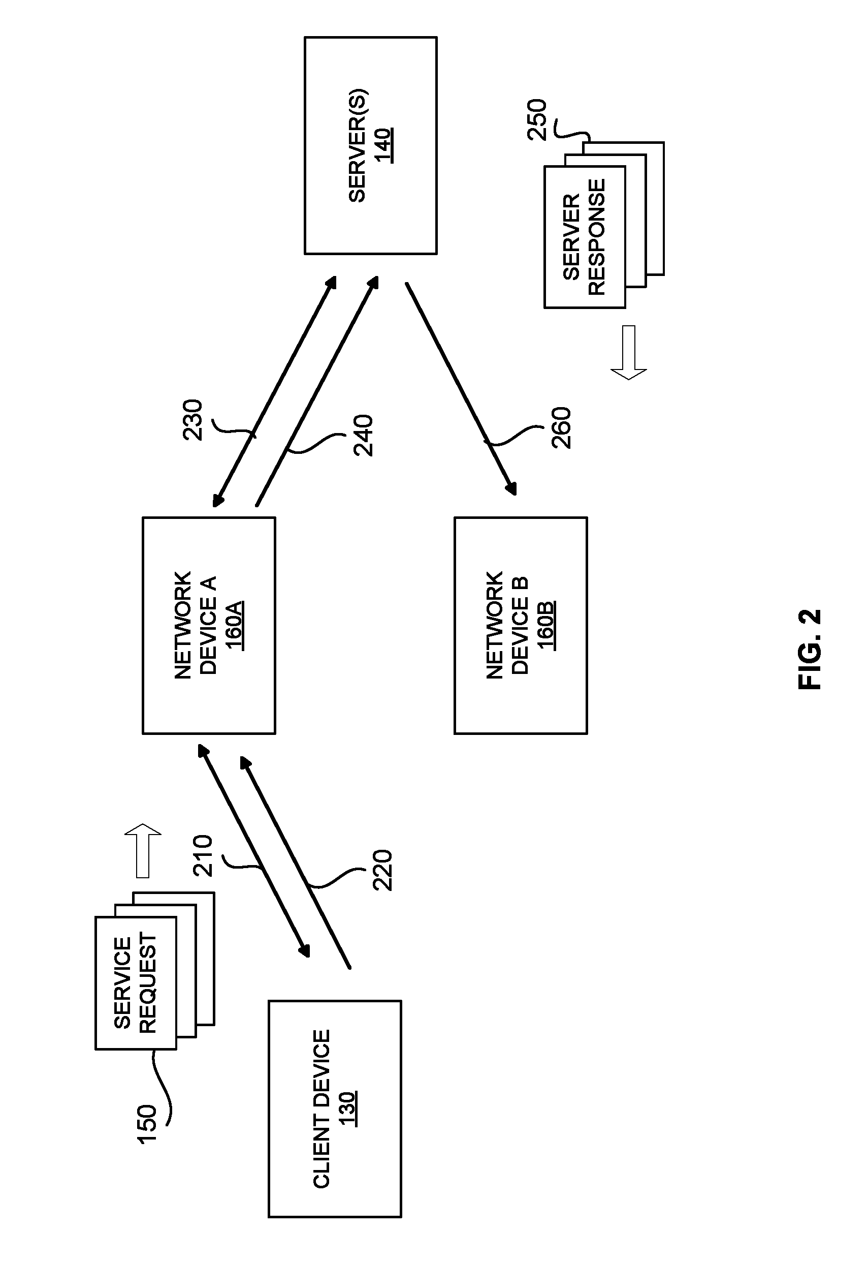
FIG. 2 shows a flow for a data packet during a planned network change for an existing service, according to an example embodiment.
FIG. 3 shows a flow for a data packet during a planned network change, utilizing dual operation of two network devices to provide the service, according to an example embodiment.
FIG. 4 shows a diagrammatic representation of a computing device for a machine in the example electronic form of a computer system, within which a set of instructions for causing the machine to perform any one or more of the methodologies discussed herein can be executed.
DETAILED DESCRIPTION
The following detailed description includes references to the accompanying drawings, which form a part of the detailed description. The drawings show illustrations in accordance with example embodiments. These example embodiments, which are also referred to herein as "examples," are described in enough detail to enable those skilled in the art to practice the present subject matter. The embodiments can be combined, other embodiments can be utilized, or structural, logical, and electrical changes can be made without departing from the scope of what is claimed. The following detailed description is therefore not to be taken in a limiting sense, and the scope is defined by the appended claims and their equivalents. In this document, the terms "a" and "an" are used, as is common in patent documents, to include one or more than one. In this document, the term "or" is used to refer to a nonexclusive "or," such that "A or B" includes "A but not B," "B but not A," and "A and B," unless otherwise indicated.
Embodiments disclosed herein may be implemented using a variety of technologies. For example, the methods described herein may be implemented in software executing on a computer system or in hardware utilizing either a combination of microprocessors or other specially designed application-specific integrated circuits (ASICs), programmable logic devices like FPGA's, or various combinations thereof. In particular, the methods described herein may be implemented by a series of computer-executable instructions residing on a storage medium such as a disk drive, or computer-readable medium. It should be noted that methods disclosed herein can be implemented by a computer, e.g., a desktop computer, tablet computer, laptop computer, smartphone and so forth.
The present technology provides various methods for operation of ADCs and GSLBs in data networks such as the Internet including a plurality of switches, routers, virtual switches, web farms, host servers, and other units. The present technology provides enhanced performance of ADC and allows implementing scalable business solutions for any services, applications, clouds and organizations. Furthermore, the present technology provides a scalable, high-performance application networking platform, which can deliver superior reliability and energy efficiency at lower total cost of ownership. An ADC can also provide increased infrastructure efficiency, a faster end user experience, comprehensive Layer 4-7 feature set and flexible virtualization technologies such as Virtual Chassis System, multi-tenancy, and more for public, private and hybrid cloud environments. The ADC and GSLB may include software and/or hardware components/platforms that may vary depending on a particular application, performance, infrastructure, network capacity, data traffic parameters, and so forth. The functionality of application delivery controllers and load balancers are also described in more detail in U.S. patent application Ser. No. 13/791,760 entitled "Application Delivery Controller and Global Server Load Balancer" which is incorporated herein by reference in its entirety.
Exemplary embodiments of the presently disclosed technology are deployed on a Layer 7 TCP/IP network. A TCP network session may be established between any two devices in the network via the TCP "handshake". This is described in more detail in U.S. patent application Ser. No. 13/413,191 entitled "System and Method for an Adaptive TCP Syn Cookie with Time Validation" which is incorporated herein by reference in its entirety.
Referring now to the drawings, FIG. 1 illustrates an environment 100 within which a service may be provided to a user from one or more servers over a network. The environment 100 may include a network 110, a client 120, a client device 130, one or more network devices 160 for distributing network traffic, and one or more servers 140. The client 120 may include a user or a host associated with the network 110.
The network 110 may include the Internet or any other network capable of communicating data between devices. Suitable networks may include or interface with any one or more of, for instance, a local intranet, a PAN (Personal Area Network), a LAN (Local Area Network), a WAN (Wide Area Network), a MAN (Metropolitan Area Network), a virtual private network (VPN), a storage area network (SAN), a frame relay connection, an Advanced Intelligent Network (AIN) connection, a synchronous optical network (SONET) connection, a digital T1, T3, E1 or E3 line, Digital Data Service (DDS) connection, DSL (Digital Subscriber Line) connection, an Ethernet connection, an ISDN (Integrated Services Digital Network) line, a dial-up port such as a V.90, V.34 or V.34bis analog modem connection, a cable modem, an ATM (Asynchronous Transfer Mode) connection, or an FDDI (Fiber Distributed Data Interface) or CDDI (Copper Distributed Data Interface) connection. Furthermore, communications may also include links to any of a variety of wireless networks, including WAP (Wireless Application Protocol), GPRS (General Packet Radio Service), GSM (Global System for Mobile Communication), CDMA (Code Division Multiple Access) or TDMA (Time Division Multiple Access), cellular phone networks, GPS (Global Positioning System), CDPD (cellular digital packet data), RIM (Research in Motion, Limited) duplex paging network, Bluetooth radio, or an IEEE 802.11-based radio frequency network.
The network 110 can further include or interface with any one or more of an RS-232 serial connection, an IEEE-1394 (Firewire) connection, a Fiber Channel connection, an IrDA (infrared) port, a SCSI (Small Computer Systems Interface) connection, a USB (Universal Serial Bus) connection or other wired or wireless, digital or analog interface or connection, mesh or Digi.RTM. networking. The network 110 may include a network of data processing nodes that are interconnected for the purpose of data communication. The network 110 may include software driven network (SDN). The SDN may include one or more of the above network types. Generally, the network 110 may include a number of similar or dissimilar devices connected together by a transport medium enabling communication between the devices by using a predefined protocol. Those skilled in the art will recognize that the present disclosure may be practiced within a variety of network configuration environments and on a variety of computing devices.
As shown in FIG. 1, the client 120 may send one or more service requests 150 to (backend) servers 140 through a client device 130. The service requests 150 may include an HTTP request, a video streaming request, a file download request, a transaction request, a conference request, or any other service provided over a network. The client device 130 may include an end user computer, mobile phone, tablet, thin client, or any other device from which a user may access the service.
The servers 140 may include a web server, a wireless application server, an interactive television server, and so forth. The network device(s) 160 may include an ADC, GSLB, LB, or any other mechanism for service load distribution. The network device 160 may balance the flow of the service requests 150 among traffic forwarding devices of the network 110. The load balancing may enhance utilization of resources and enable maximize throughput with minimum response time, hence avoiding overloading of a single server. With this technology, network traffic may be distributed among different web farms, data centers, and servers 140 located at different geographical locations. Furthermore, as will be appreciated by those skilled in the art, network device 160 may act as a master to monitor "health" and responsiveness of services hosted by the servers 140.
The network device 160 may also analyze the flow of the service requests 150 and determine which and how many traffic forwarding devices of the network 110 are needed to deliver the service requests 150 to the servers 140.
The network device 160 may also inspect incoming data packets and apply data policies or algorithms to determine the server(s) to deliver the service requests to. The policy may be a forwarding policy, security policy, service policy, or any other type of policy. In exemplary embodiments, the network device 160 may also modify the data packets as necessary before delivering the service requests 150 to the servers 140. The network device 160 may also inspect data packets and modify them as necessary in the server to client traffic direction.
FIG. 2 illustrates an exemplary flow for a data packet during a planned network change for an existing service provided to a user from one or more servers over a network. The steps of the flow may be performed in varying orders or concurrently. In various embodiments, the flow illustrated in FIG. 2 may apply to data packets of Layer 7 sessions. In flow 210, a client device 130 conducts a TCP handshake with network device A 160A and establishes a TCP network session with network device 160A. The TCP handshake may comprise the exchange of a SYN packet, SYN/ACK packet, and ACK packet, as understood by a person of ordinary skill in the art. In flow 220, the client device 130 may then send a service request to network device 160A. The service request may be for a virtual IP address, HTTP, GET, etc. In exemplary embodiments, network device 160A may then determine which server to deliver the service request to by conducting load balancing on a plurality of servers that are designated for the service. Network device 160A may then conduct a TCP handshake with the designated server 140 to establish a TCP network session between these two devices in flow 230. Alternatively, network device 160A may use an existing TCP network session with a server 140. The network device 160A may then deliver the service request to the server(s) in flow 240. The server 140 may be a server computer, load balancer, ADC, or any other network component.
During normal operation, the server 140 may then process the service request 150 and generate a server response 250, which is delivered to network device 160A, and forwarded to client device 130. One or more security, forwarding, or other policies may also be employed at any stage of this process.
During a planned network change (such as an upgrade or downgrade of network device 160A), the network administrator may choose to remove network device 160A as the active device for any reason, and configure an additional network device 160B as the active device. Network device 160B may be a surplus network device previously connected to the network 110, or a new device added to the network for the planned network change. Network device 160B may have previously been configured as a backup for network device 160A, or may have been an active device for a different virtual service.
In an exemplary embodiment, once network device 160B has been configured as the active device for the virtual service, the server response 250 is delivered to network device 160B via flow 260. However, since network device 160B does not have the open TCP session with client device 130 for the service request 150, it will not recognize the network session for the server response 250. As such, network device 160B may not know where to deliver server response 250 and may simply drop the data packet(s) from the server, resulting in a loss of data. When client device 130 does not receive server response 250 after a designated amount of time, it may have to re-send service request 150 to start the process of requesting the service again.
FIG. 3 illustrates an exemplary embodiment of a flow for a data packet during a planned network change, utilizing dual operation of two network devices to provide the service over the network. The steps of the flow may be performed in varying orders or concurrently. In various embodiments, the flow illustrated in FIG. 3 may apply to data packets of Layer 7 sessions.
In preparation for a planned network change, such as an upgrade or downgrade, of network device 160A, a second network device 160B may be deployed as a standby or backup device to the active network device 160A. In exemplary embodiments, the standby network device 160B may be upgraded or downgrade first, before being deployed in the network. Alternatively, standby network device 160B may be upgraded or downgraded after network device 160A.
In an example embodiment, a client device 130 may conduct a TCP handshake with network device 160A and establish a TCP network session with network device 160A in flow 310. The TCP handshake may comprise the exchange of a SYN packet, SYN/ACK packet, and ACK packet, as understood by a person of ordinary skill in the art. In flow 320, network device 160A may then send information to the standby network device 160B to create a similar, local session on network device 160B. Network device 160B may then create a redirect TCP session, such that it can recognize incoming traffic originally destined for network device 160A as needing to be redirected to network device 160A. The redirect session created at network device 160B may comprise all of the data contained in the network session, or may contain only certain identifying information needed to recognize the network session. For example, the redirect session may contain only the source IP address, destination IP address, source port, destination port, and network protocol. Fewer or additional components may be a part of the redirect session, as will be understood by a person of ordinary skill in the art.
In flow 330, client device 130 may then send a service request 150 to network device 160A, since it is still the active network device for the service. The service request may be for a virtual IP address, HTTP, GET, etc. In exemplary embodiments, network device 160A may determine which server to deliver the service request to by conducting load balancing on a plurality of servers that are designated for the service. Network device 160A may then conduct a TCP handshake with the designated server 140 to establish a TCP network session between these two devices in flow 340. Alternatively, network device 160A may use an existing TCP network session with a server 140. The network device 160A may then deliver the service request to the server(s) in flow 350. The server 140 may be a server computer, load balancer, ADC, or any other network component.
In an example embodiment, the network administrator may decide to switch the active network device for the virtual service from network device 160A to network device 160B, in order to prepare network device 160A for upgrade. When the server 140 processes the service request 150, it may generate a server response 250, which may then be delivered to network device 160B in flow 360, since this is now the active device for the service. Network device 160B may then recognize information in the data packet(s) of server response 250 as being a part of the redirect session that originated from network device 160A. Network device 160B may then redirect server response 250 to network device 160A in flow 370, since that is the device for which the client device 130 has established the TCP session. In exemplary embodiments, network device 160B may also conduct a session lookup to match the received data in flow 360 with the redirect session entry created in flow 320. Network device 160B may match one or more of source IP address, destination IP address, source port, destination port, protocol, or any other information from the network session. The server response 250 may then be delivered to client device 130 in flow 380. One or more security, forwarding, or other policies may also be employed at any stage of this process as well.
In various embodiments, after network device 160B has been configured as the active device for the service, a new service request 150 from client device 130 may be directed to network device 160B, since it is now the active device. In these embodiments, network device 160B may receive the service request 150 from client device 130 and deliver the request to the server 140. Network device 160B may also receive the server response 250 and deliver it to the client device 130. However, a server response 250 from a service request 150 that was previously received by network device 160A, may continue to be redirected to network device 160A. As such, the two network devices 160A and 160B may both be handling service requests from client device 130 for a period of time.
The dual operation of network devices 160A and 160B may continue until all of the existing sessions from network device 160A have timed out or are completed. Once network device 160A has finished processing all of its existing sessions, it may be ready for upgrade or downgrade. Existing sessions from network device 160A may also be marked to time out faster or slower so that the planned network change can occur at a specific time. By waiting until network device 160A no longer has any open network sessions, the device may be upgraded or downgraded without any resulting data loss in the network. Additionally, client device 130 may receive the service seamlessly and without disruption over the network.
While embodiments have been described herein in the context of a single client 120 and client device 130, it will be understood by persons of ordinary skill in the art that any number of clients and client devices may be able to access a service of a network in a similar manner. Additionally, while the example embodiments have been depicted in FIGS. 2 and 3 with a single active network device and a single standby network device, any number of network devices may be utilized in a similar manner.
FIG. 4 shows a diagrammatic representation of a machine in the example electronic form of a computer system 400, within which a set of instructions for causing the machine to perform any one or more of the methodologies discussed herein may be executed. In various example embodiments, the machine operates as a standalone device or may be connected (e.g., networked) to other machines. In a networked deployment, the machine may operate in the capacity of a server or a client machine in a server-client network environment, or as a peer machine in a peer-to-peer (or distributed) network environment. The machine may be a PC, a tablet PC, a set-top box (STB), a cellular telephone, a portable music player (e.g., a portable hard drive audio device such as a Moving Picture Experts Group Audio Layer 3 (MP3) player), a web appliance, a network router, switch or bridge, or any machine capable of executing a set of instructions (sequential or otherwise) that specify actions to be taken by that machine. Further, while only a single machine is illustrated, the term "machine" shall also be taken to include any collection of machines that individually or jointly execute a set (or multiple sets) of instructions to perform any one or more of the methodologies discussed herein.
The example computer system 400 includes a processor or multiple processors 402 (e.g., a central processing unit (CPU), a graphics processing unit (GPU), or both), a main memory 404 and a static memory 406, which communicate with each other via a bus 408. The computer system 400 may further include a video display unit 410 (e.g., a liquid crystal display (LCD) or a cathode ray tube (CRT)). The computer system 400 may also include an alpha-numeric input device 412 (e.g., a keyboard), a cursor control device 414 (e.g., a mouse), a disk drive unit 416, a signal generation device 418 (e.g., a speaker), and a network interface device 420.
The disk drive unit 416 includes a non-transitory computer-readable medium 422, on which is stored one or more sets of instructions and data structures (e.g., instructions 424) embodying or utilized by any one or more of the methodologies or functions described herein. The instructions 424 may also reside, completely or at least partially, within the main memory 404 and/or within the processors 402 during execution thereof by the computer system 400. The main memory 404 and the processors 402 may also constitute machine-readable media.
The instructions 424 may further be transmitted or received over a network 426 via the network interface device 420 utilizing any one of a number of well-known transfer protocols (e.g., Hyper Text Transfer Protocol (HTTP)).
While the computer-readable medium 422 is shown in an example embodiment to be a single medium, the term "computer-readable medium" should be taken to include a single medium or multiple media (e.g., a centralized or distributed database and/or associated caches and servers) that store the one or more sets of instructions. The term "computer-readable medium" shall also be taken to include any medium that is capable of storing, encoding, or carrying a set of instructions for execution by the machine and that causes the machine to perform any one or more of the methodologies of the present application, or that is capable of storing, encoding, or carrying data structures utilized by or associated with such a set of instructions. The term "computer-readable medium" shall accordingly be taken to include, but not be limited to, solid-state memories, optical and magnetic media, and carrier wave signals. Such media may also include, without limitation, hard disks, floppy disks, flash memory cards, digital video disks, random access memory (RAMs), read only memory (ROMs), and the like.
The example embodiments described herein can be implemented in an operating environment comprising computer-executable instructions (e.g., software) installed on a computer, in hardware, or in a combination of software and hardware. The computer-executable instructions can be written in a computer programming language or can be embodied in firmware logic. If written in a programming language conforming to a recognized standard, such instructions can be executed on a variety of hardware platforms and for interfaces to a variety of operating systems. Although not limited thereto, computer software programs for implementing the present method can be written in any number of suitable programming languages such as, for example, Hypertext Markup Language (HTML), Dynamic HTML, Extensible Markup Language (XML), Extensible Stylesheet Language (XSL), Document Style Semantics and Specification Language (DSSSL), Cascading Style Sheets (CSS), Synchronized Multimedia Integration Language (SMIL), Wireless Markup Language (WML), Java.TM., Jini.TM., C, C++, Perl, UNIX Shell, Visual Basic or Visual Basic Script, Virtual Reality Markup Language (VRML), ColdFusion.TM. or other compilers, assemblers, interpreters or other computer languages or platforms.
Thus, methods and systems for enabling planned upgrades and downgrades of a network device with minimum to no impact on network sessions are disclosed. Although embodiments have been described with reference to specific example embodiments, it will be evident that various modifications and changes can be made to these example embodiments without departing from the broader spirit and scope of the present application. Accordingly, the specification and drawings are to be regarded in an illustrative rather than a restrictive sense.
* * * * *
References
-
cisco.com/c/en/us/td/docs/ios/12_0s/feature/guide/s_mvesoo.html
-
-
freebsd.org/cgi/man.cgi?query=tcp&apropos=0&sektion=7&manpath=SuSe+Linux%2Fi386+11.0&format=asci
-
cyberciti.biz/faq/linux-tcp-tuning
-
example.com:80isaservicethatisbeingloadbalancedandthereisagroupofserversthathostthisservice
D00000
D00001
D00002
D00003
D00004
XML
uspto.report is an independent third-party trademark research tool that is not affiliated, endorsed, or sponsored by the United States Patent and Trademark Office (USPTO) or any other governmental organization. The information provided by uspto.report is based on publicly available data at the time of writing and is intended for informational purposes only.
While we strive to provide accurate and up-to-date information, we do not guarantee the accuracy, completeness, reliability, or suitability of the information displayed on this site. The use of this site is at your own risk. Any reliance you place on such information is therefore strictly at your own risk.
All official trademark data, including owner information, should be verified by visiting the official USPTO website at www.uspto.gov. This site is not intended to replace professional legal advice and should not be used as a substitute for consulting with a legal professional who is knowledgeable about trademark law.