Database migration
Bigman , et al. Sept
U.S. patent number 10,409,787 [Application Number 14/978,378] was granted by the patent office on 2019-09-10 for database migration. This patent grant is currently assigned to EMC IP HOLDING COMPANY LLC. The grantee listed for this patent is EMC Corporation. Invention is credited to Ron Bigman, Amit Lieberman, Assaf Natanzon, Oded Peer, Jehuda Shemer, Yana Vaisman.


| United States Patent | 10,409,787 |
| Bigman , et al. | September 10, 2019 |
Database migration
Abstract
In one aspect, a method includes migrating a database object from a source database to a target database, updating a storage of the location of the DB object to be the target database, directly accessing one of the target database and the source database during the migrating and executing, during the migrating, a database command by retrieving the DB object from the other one of the target database and the source database.
| Inventors: | Bigman; Ron (Holon, IL), Natanzon; Assaf (Tel Aviv, IL), Shemer; Jehuda (Kfar Saba, IL), Lieberman; Amit (Raanana, IL), Vaisman; Yana (Netanya, IL), Peer; Oded (Raanana, IL) | ||||||||||
|---|---|---|---|---|---|---|---|---|---|---|---|
| Applicant: |
|
||||||||||
| Assignee: | EMC IP HOLDING COMPANY LLC
(Hopkinton, MA) |
||||||||||
| Family ID: | 67845281 | ||||||||||
| Appl. No.: | 14/978,378 | ||||||||||
| Filed: | December 22, 2015 |
| Current U.S. Class: | 1/1 |
| Current CPC Class: | G06F 16/22 (20190101); G06F 16/214 (20190101); G06F 40/205 (20200101) |
| Current International Class: | G06F 16/21 (20190101); G06F 7/00 (20060101); G06F 16/22 (20190101); G06F 17/27 (20060101) |
| Field of Search: | ;707/809 |
References Cited [Referenced By]
U.S. Patent Documents
| 7203741 | April 2007 | Marco et al. |
| 7719443 | May 2010 | Natanzon |
| 7840536 | November 2010 | Ahal et al. |
| 7840662 | November 2010 | Natanzon |
| 7844856 | November 2010 | Ahal et al. |
| 7860836 | December 2010 | Natanzon et al. |
| 7882286 | February 2011 | Natanzon et al. |
| 7934262 | April 2011 | Natanzon et al. |
| 7958372 | June 2011 | Natanzon |
| 8037162 | October 2011 | Marco et al. |
| 8041940 | October 2011 | Natanzon et al. |
| 8060713 | November 2011 | Natanzon |
| 8060714 | November 2011 | Natanzon |
| 8103937 | January 2012 | Natanzon et al. |
| 8108634 | January 2012 | Natanzon et al. |
| 8214612 | July 2012 | Natanzon |
| 8250149 | August 2012 | Marco et al. |
| 8271441 | September 2012 | Natanzon et al. |
| 8271447 | September 2012 | Natanzon et al. |
| 8332687 | December 2012 | Natanzon et al. |
| 8335761 | December 2012 | Natanzon |
| 8335771 | December 2012 | Natanzon et al. |
| 8341115 | December 2012 | Natanzon et al. |
| 8370648 | February 2013 | Natanzon |
| 8380885 | February 2013 | Natanzon |
| 8392680 | March 2013 | Natanzon et al. |
| 8429362 | April 2013 | Natanzon et al. |
| 8433869 | April 2013 | Natanzon et al. |
| 8438135 | May 2013 | Natanzon et al. |
| 8464101 | June 2013 | Natanzon et al. |
| 8478955 | July 2013 | Natanzon et al. |
| 8495304 | July 2013 | Natanzon et al. |
| 8510279 | August 2013 | Natanzon et al. |
| 8521691 | August 2013 | Natanzon |
| 8521694 | August 2013 | Natanzon |
| 8543609 | September 2013 | Natanzon |
| 8583885 | November 2013 | Natanzon |
| 8600945 | December 2013 | Natanzon et al. |
| 8601085 | December 2013 | Ives et al. |
| 8627012 | January 2014 | Derbeko et al. |
| 8683592 | March 2014 | Dotan et al. |
| 8694700 | April 2014 | Natanzon et al. |
| 8706700 | April 2014 | Natanzon et al. |
| 8712962 | April 2014 | Natanzon et al. |
| 8719497 | May 2014 | Don et al. |
| 8725691 | May 2014 | Natanzon |
| 8725692 | May 2014 | Natanzon et al. |
| 8726066 | May 2014 | Natanzon et al. |
| 8738813 | May 2014 | Natanzon et al. |
| 8745004 | June 2014 | Natanzon et al. |
| 8751828 | June 2014 | Raizen et al. |
| 8769336 | July 2014 | Natanzon et al. |
| 8805786 | August 2014 | Natanzon |
| 8806161 | August 2014 | Natanzon |
| 8825848 | September 2014 | Dotan et al. |
| 8832399 | September 2014 | Natanzon et al. |
| 8850143 | September 2014 | Natanzon |
| 8850144 | September 2014 | Natanzon et al. |
| 8862546 | October 2014 | Natanzon et al. |
| 8892835 | November 2014 | Natanzon et al. |
| 8898112 | November 2014 | Natanzon et al. |
| 8898409 | November 2014 | Natanzon et al. |
| 8898515 | November 2014 | Natanzon |
| 8898519 | November 2014 | Natanzon et al. |
| 8914595 | December 2014 | Natanzon |
| 8924668 | December 2014 | Natanzon |
| 8930500 | January 2015 | Marco et al. |
| 8930947 | January 2015 | Derbeko et al. |
| 8935498 | January 2015 | Natanzon |
| 8949180 | February 2015 | Natanzon et al. |
| 8954673 | February 2015 | Natanzon et al. |
| 8954796 | February 2015 | Cohen et al. |
| 8959054 | February 2015 | Natanzon |
| 8977593 | March 2015 | Natanzon et al. |
| 8977826 | March 2015 | Meiri et al. |
| 8996460 | March 2015 | Frank et al. |
| 8996461 | March 2015 | Natanzon et al. |
| 8996827 | March 2015 | Natanzon |
| 9003138 | April 2015 | Natanzon et al. |
| 9003149 | April 2015 | Kathmann |
| 9026696 | May 2015 | Natanzon et al. |
| 9031913 | May 2015 | Natanzon |
| 9032160 | May 2015 | Natanzon et al. |
| 9037818 | May 2015 | Natanzon et al. |
| 9063994 | June 2015 | Natanzon et al. |
| 9069479 | June 2015 | Natanzon |
| 9069709 | June 2015 | Natanzon et al. |
| 9081754 | July 2015 | Natanzon et al. |
| 9081842 | July 2015 | Natanzon et al. |
| 9087008 | July 2015 | Natanzon |
| 9087112 | July 2015 | Natanzon et al. |
| 9104529 | August 2015 | Derbeko et al. |
| 9110914 | August 2015 | Frank et al. |
| 9116811 | August 2015 | Derbeko et al. |
| 9128628 | September 2015 | Natanzon et al. |
| 9128855 | September 2015 | Natanzon et al. |
| 9134914 | September 2015 | Derbeko et al. |
| 9135119 | September 2015 | Natanzon et al. |
| 9135120 | September 2015 | Natanzon |
| 9146878 | September 2015 | Cohen et al. |
| 9152339 | October 2015 | Cohen et al. |
| 9152578 | October 2015 | Saad et al. |
| 9152814 | October 2015 | Natanzon |
| 9158578 | October 2015 | Derbeko et al. |
| 9158630 | October 2015 | Natanzon |
| 9160526 | October 2015 | Raizen et al. |
| 9177670 | November 2015 | Derbeko et al. |
| 9189339 | November 2015 | Cohen et al. |
| 9189341 | November 2015 | Natanzon et al. |
| 9201736 | December 2015 | Moore et al. |
| 9223659 | December 2015 | Natanzon et al. |
| 9225529 | December 2015 | Natanzon et al. |
| 9235481 | January 2016 | Natanzon et al. |
| 9235524 | January 2016 | Derbeko et al. |
| 9235632 | January 2016 | Natanzon |
| 9244997 | January 2016 | Natanzon et al. |
| 9256605 | February 2016 | Natanzon |
| 9274718 | March 2016 | Natanzon et al. |
| 9275063 | March 2016 | Natanzon |
| 9286052 | March 2016 | Solan et al. |
| 9305009 | April 2016 | Bono et al. |
| 9323750 | April 2016 | Natanzon et al. |
| 9330155 | May 2016 | Bono et al. |
| 9336094 | May 2016 | Wolfson et al. |
| 9336230 | May 2016 | Natanzon |
| 9367260 | June 2016 | Natanzon |
| 9378096 | June 2016 | Erel et al. |
| 9378219 | June 2016 | Bono et al. |
| 9378261 | June 2016 | Bono et al. |
| 9383937 | July 2016 | Frank et al. |
| 9389800 | July 2016 | Natanzon et al. |
| 9405481 | August 2016 | Cohen et al. |
| 9405684 | August 2016 | Derbeko et al. |
| 9405765 | August 2016 | Natanzon |
| 9411535 | August 2016 | Shemer et al. |
| 9459804 | October 2016 | Natanzon et al. |
| 9460028 | October 2016 | Raizen et al. |
| 9471579 | October 2016 | Natanzon |
| 9477407 | October 2016 | Marshak et al. |
| 9501542 | November 2016 | Natanzon |
| 9507732 | November 2016 | Natanzon et al. |
| 9507845 | November 2016 | Natanzon et al. |
| 9514138 | December 2016 | Natanzon et al. |
| 9524218 | December 2016 | Veprinsky et al. |
| 9529885 | December 2016 | Natanzon et al. |
| 9535800 | January 2017 | Natanzon et al. |
| 9535801 | January 2017 | Natanzon et al. |
| 9547459 | January 2017 | BenHanokh et al. |
| 9547591 | January 2017 | Natanzon et al. |
| 9552405 | January 2017 | Moore et al. |
| 9557921 | January 2017 | Cohen et al. |
| 9557925 | January 2017 | Natanzon |
| 9563517 | February 2017 | Natanzon et al. |
| 9563684 | February 2017 | Natanzon et al. |
| 9575851 | February 2017 | Natanzon et al. |
| 9575857 | February 2017 | Natanzon |
| 9575894 | February 2017 | Natanzon et al. |
| 9582382 | February 2017 | Natanzon et al. |
| 9588703 | March 2017 | Natanzon et al. |
| 9588847 | March 2017 | Natanzon et al. |
| 9594822 | March 2017 | Natanzon et al. |
| 9600377 | March 2017 | Cohen et al. |
| 9619543 | April 2017 | Natanzon et al. |
| 9632881 | April 2017 | Natanzon |
| 9665305 | May 2017 | Natanzon et al. |
| 9710177 | July 2017 | Natanzon |
| 9720618 | August 2017 | Panidis et al. |
| 9722788 | August 2017 | Natanzon et al. |
| 9727429 | August 2017 | Moore et al. |
| 9733969 | August 2017 | Derbeko et al. |
| 9737111 | August 2017 | Lustik |
| 9740572 | August 2017 | Natanzon et al. |
| 9740573 | August 2017 | Natanzon |
| 9740880 | August 2017 | Natanzon et al. |
| 9749300 | August 2017 | Cale et al. |
| 9772789 | September 2017 | Natanzon et al. |
| 9798472 | October 2017 | Natanzon et al. |
| 9798490 | October 2017 | Natanzon |
| 9804934 | October 2017 | Natanzon et al. |
| 9811431 | November 2017 | Natanzon et al. |
| 9823865 | November 2017 | Natanzon et al. |
| 9823973 | November 2017 | Natanzon |
| 9832261 | November 2017 | Don et al. |
| 9846698 | December 2017 | Panidis et al. |
| 9875042 | January 2018 | Natanzon et al. |
| 9875162 | January 2018 | Panidis et al. |
| 9880777 | January 2018 | Bono et al. |
| 9881014 | January 2018 | Bono et al. |
| 9910620 | March 2018 | Veprinsky et al. |
| 9910621 | March 2018 | Golan et al. |
| 9910735 | March 2018 | Natanzon |
| 9910739 | March 2018 | Natanzon et al. |
| 9917854 | March 2018 | Natanzon et al. |
| 9921955 | March 2018 | Derbeko et al. |
| 9933957 | April 2018 | Cohen et al. |
| 9934302 | April 2018 | Cohen et al. |
| 9940205 | April 2018 | Natanzon |
| 9940460 | April 2018 | Derbeko et al. |
| 9946649 | April 2018 | Natanzon et al. |
| 9959061 | May 2018 | Natanzon et al. |
| 9965306 | May 2018 | Natanzon et al. |
| 9990256 | June 2018 | Natanzon |
| 9996539 | June 2018 | Natanzon |
| 10007626 | June 2018 | Saad et al. |
| 10019194 | July 2018 | Baruch et al. |
| 10025931 | July 2018 | Natanzon et al. |
| 10031675 | July 2018 | Veprinsky et al. |
| 10031690 | July 2018 | Panidis et al. |
| 10031692 | July 2018 | Elron et al. |
| 10031703 | July 2018 | Natanzon et al. |
| 10037251 | July 2018 | Bono et al. |
| 10042579 | August 2018 | Natanzon |
| 10042751 | August 2018 | Veprinsky et al. |
| 10055146 | August 2018 | Natanzon et al. |
| 10055148 | August 2018 | Natanzon et al. |
| 10061666 | August 2018 | Natanzon et al. |
| 10067694 | September 2018 | Natanzon et al. |
| 10067837 | September 2018 | Natanzon et al. |
| 10078459 | September 2018 | Natanzon et al. |
| 10082980 | September 2018 | Cohen et al. |
| 10083093 | September 2018 | Natanzon et al. |
| 10095489 | October 2018 | Lieberman et al. |
| 10101943 | October 2018 | Ayzenberg et al. |
| 10108356 | October 2018 | Natanzon et al. |
| 10108507 | October 2018 | Natanzon |
| 10108645 | October 2018 | Bigman et al. |
| 10114581 | October 2018 | Natanzon et al. |
| 10120787 | November 2018 | Shemer et al. |
| 10120925 | November 2018 | Natanzon et al. |
| 10126946 | November 2018 | Natanzon et al. |
| 10133874 | November 2018 | Natanzon et al. |
| 10140039 | November 2018 | Baruch et al. |
| 10146436 | December 2018 | Natanzon et al. |
| 10146639 | December 2018 | Natanzon et al. |
| 10146675 | December 2018 | Shemer et al. |
| 10146961 | December 2018 | Baruch et al. |
| 10148751 | December 2018 | Natanzon |
| 10152246 | December 2018 | Lieberman et al. |
| 10152267 | December 2018 | Ayzenberg et al. |
| 10152384 | December 2018 | Amit et al. |
| 10157014 | December 2018 | Panidis et al. |
| 10185583 | January 2019 | Natanzon et al. |
| 10191677 | January 2019 | Natanzon et al. |
| 10191687 | January 2019 | Baruch et al. |
| 10191755 | January 2019 | Natanzon et al. |
| 10203904 | February 2019 | Natanzon et al. |
| 10210073 | February 2019 | Baruch et al. |
| 10223007 | March 2019 | Natanzon et al. |
| 10223023 | March 2019 | Natanzon et al. |
| 10223131 | March 2019 | Lieberman et al. |
| 10229006 | March 2019 | Natanzon et al. |
| 10229056 | March 2019 | Panidis et al. |
| 2011/0295804 | December 2011 | Erofeev |
| 2014/0379768 | December 2014 | Matsuzawa |
| 2015/0169239 | June 2015 | Sakai |
| 2015/0234617 | August 2015 | Li |
| 2017/0064030 | March 2017 | Maskalik |
Other References
|
US. Appl. No. 14/496,783, filed Sep. 25, 2014, Natanzon et al. cited by applicant . U.S. Appl. No. 14/496,790, filed Sep. 25, 2014, Cohen et al. cited by applicant . U.S. Appl. No. 14/559,036, filed Dec. 3, 2014, Natanzon et al. cited by applicant . U.S. Appl. No. 14/753,389, filed Jun. 29, 2015, Nir et al. cited by applicant . U.S. Appl. No. 14/976,719, filed Dec. 21, 2015, Natanzon. cited by applicant . U.S. Appl. No. 15/085,148, filed Mar. 30, 2016, Baruch et al. cited by applicant . U.S. Appl. No. 15/274,362, filed Sep. 23, 2016, Baruch et al. cited by applicant . U.S. Appl. No. 15/275,768, filed Sep. 26, 2016, Natanzon et al. cited by applicant . U.S. Appl. No. 15/275,756, filed Sep. 26, 2016, Natanzon et al. cited by applicant . U.S. Appl. No. 15/379,940, filed Dec. 15, 2016, Baruch et al. cited by applicant . U.S. Appl. No. 15/386,754, filed Dec. 21, 2016, Sherner et al. cited by applicant . U.S. Appl. No. 15/380,013, filed Dec. 15, 2016, Baruch et al. cited by applicant . U.S. Appl. No. 15/390,996, filed Dec. 27, 2016, Natanzon et al. cited by applicant . U.S. Appl. No. 15/391,030, filed Dec. 27, 2016, Shemer et al. cited by applicant . U.S. Appl. No. 15/970,243, filed May 3, 2018, Schneider et al. cited by applicant . U.S. Appl. No. 16/052,037, filed Aug. 1, 2018, Schneider et al. cited by applicant . U.S. Appl. No. 16/048,763, filed Jul. 30, 2018, Schneider et aL. cited by applicant . U.S. Appl. No. 16/050,400, filed Jul. 31, 2018, Alkalay et al. cited by applicant . U.S. Appl. No. 16/179,295, filed Nov. 2, 2018, Natanzan et al. cited by applicant . U.S. Appl. No. 16/261,174, filed Jan. 29, 2019, Natanzon et al. cited by applicant. |
Primary Examiner: Lu; Kuen S
Attorney, Agent or Firm: Daly, Crowley Mofford & Durkee, LLP
Claims
What is claimed is:
1. A method for migrating a source database to a target database, the method comprising: establishing a communication link, via an abstraction layer of a host computer, between the source database and the target database; migrating, via the abstraction layer, database (DB) objects from the source database to the target database, wherein during the migrating the method further comprises: for each of the DB objects, updating, at the host computer, a storage of the location of the corresponding DB object to be the target database, the location stored in a table; intercepting a database command, by the abstraction layer from an application of the host computer, the abstraction layer transparent to the application; identifying, from the table, in which of the source database and the target database a corresponding DB object subject to the database command resides; directly accessing one of the target database and the source database in which the DB object subject to the database command resides; and executing the database command by retrieving the DB object from the one of the target database and the source database.
2. The method of claim 1, wherein at least one of the DB objects is a table, the migrating further comprising: moving records of the table from the source database to the target database; and after moving the records, moving records that have changed to the target database.
3. The method of claim 2, further comprising keeping the records that have changed aside until the records of the table have moved to the target database.
4. The method of claim 2, further comprising stopping write operations to the table, if a number of record changes is smaller than a threshold number.
5. The method of claim 1, wherein at least one of the database objects is a table, the migrating further comprising stopping write operations to a first table of the database until after the first table has been migrated by parsing writes to the first table.
6. The method of claim 1, further comprising: upon determining, by the host computer, the DB object has already been migrated from the source database to the target database, applying a pointer with respect to the DB object, to point to the target database.
7. The method of claim 1, wherein the database command is a command to access multiple DB objects, the method further comprising: identifying from the table, locations in which the multiple DB objects are stored; determining from the table which of the source database and the target database stores a majority of the multiple DB objects; directly accessing the one of the source database and the target database determined to store the majority of the multiple DB objects; and remotely connecting, via the abstraction layer through one of the source database and the target database determined to store the majority, to the other one of the source database and the target database to access remaining ones of the multiple DB objects.
8. The method of claim 1, wherein the source database resides at a first cloud database service provider and the target database resides at a second cloud database service provider.
9. The method of claim 8, wherein the host computer receives database-as-a-service (DBaaS) services from the first and second cloud database service providers.
10. An apparatus for migrating a source database to a target database, the apparatus comprising: electronic hardware circuitry configured to: establish a communication link, via an abstraction layer of a host computer, between the source database and the target database; migrate, via the abstraction layer, database (DB) objects from the source database to the target database, wherein during migration the electronic hardware circuitry is further configured to: for each of the DB objects, update, at the host computer, a storage of the location of the corresponding DB object to be the target database, the location stored in a table; intercept a database command, by the abstraction layer from an application of the host computer, the abstraction layer transparent to the application; identify, from the table, in which of the source database and the target database a corresponding DB object subject to the database command resides; directly access one of the target database and the source database in which the DB object subject to the database command resides; and execute the database command by retrieving the DB object from the one of the target database and the source database.
11. The apparatus of claim 10, wherein the circuitry comprises at least one of a processor, a memory, a programmable logic device or a logic gate.
12. The apparatus of claim 10, wherein at least one of the DB objects is a table, the migrating further comprising: moving records of the table from the source database to the target database; and after moving the records, moving records that have changed to the target database.
13. The apparatus of claim 12, further comprising circuitry configured to keep the records that have changed aside until the records of the table have moved to the target database.
14. The apparatus of claim 12, further comprising circuitry configured to stop write operations to the table, if a number of record changes is smaller than a threshold number.
15. The apparatus of claim 10, wherein at least one of the database objects is a table, the migrating further comprising: stopping write operations to a first table of the database until after the first table has been migrated by parsing writes to the first table.
16. An article for migrating a source database to a target database, the article comprising: a non-transitory computer-readable medium that stores computer-executable instructions, the instructions causing a machine to: establish a communication link, via an abstraction layer of a host computer, between the source database and the target database; migrate, via the abstraction layer, a database (DB) object from the source database to the target database, wherein during migration the instructions further cause the machine to: for each of the DB objects, update, at the host computer, a storage of the location of the corresponding DB object to be the target database, the location stored in a table; intercept a database command, by the abstraction layer from an application of the host computer, the abstraction layer transparent to the application; identify, from the table, in which of the source database and the target database a corresponding DB object subject to the database command resides; directly access one of the target database and the source database in which the DB object subject to the database command resides; and execute the database command by retrieving the DB object from the other one of the target database and the source database.
17. The article of claim 16, wherein at least one of the DB objects is a table, the migrating further comprising: moving records of the table from the source database to the target database; and after moving the records, moving records that have changed to the target database.
18. The article of claim 17, further comprising instructions causing the machine to keep the records that have changed aside until the records of the table have moved to the target database.
19. The article of claim 17, further comprising instructions causing the machine to stop write operations to the table, if a number of record changes is smaller than a threshold number.
20. The article of claim 16, wherein at least one of the database objects is a table, the migrating further comprising: stopping write operations to a first table of the database until after the first table has been migrated by parsing writes to the first table.
Description
BACKGROUND
A cloud data base typically runs on a cloud computing platform. A cloud database may be formed using a Database as a Service (DBaaS). The DBaaS is a cloud computing service model that provides users with some form of access to a database (DB) without the need for setting up physical hardware, installing software or configuring for performance. DBaaS allows for DB connectivity without dealing with the DB management. The cloud database may also be generated by being installed on a virtual machine (VM) located in the cloud and requires that a user manage the database.
SUMMARY
In one aspect, a method includes migrating a database object from a source database to a target database, updating a storage of the location of the DB object to be the target database, directly accessing one of the target database and the source database during the migrating and executing, during the migrating, a database command by retrieving the DB object from the other one of the target database and the source database.
In another aspect, an apparatus includes electronic hardware circuitry configured to migrate a database object from a source database to a target database, update a storage of the location of the DB object to be the target database, directly access one of the target database and the source database during the migrating and execute, during the migrating, a database command by retrieving the DB object from the other one of the target database and the source database.
In a further aspect, an article includes a non-transitory computer-readable medium that stores computer-executable instructions. The instructions cause a machine to migrate a database object from a source database to a target database, update a storage of the location of the DB object to be the target database, directly access one of the target database and the source database during the migrating and execute, during the migrating, a database command by retrieving the DB object from the other one of the target database and the source database.
BRIEF DESCRIPTION OF THE DRAWINGS
FIG. 1 is a block diagram of an example of a system to migrate a DB from one database service to another database service, according to an embodiment of the disclosure.
FIG. 2 is a flowchart of an example of a process to migrate a DB from one database service to another database service, according to an embodiment of the disclosure.
FIG. 3 is a flowchart of an example of a process to use a target database after the process in FIG. 2 has initiated, according to an embodiment of the disclosure.
FIG. 4 is a flowchart of an example of a process to move a single table from one database service to another database service, according to an embodiment of the disclosure.
FIG. 5 is a block diagram of an example of a computer on which any portion of the process of FIGS. 2 to 4 may be implemented, according to an embodiment of the disclosure.
DETAILED DESCRIPTION
In one example, a benefit of using database as a service (DBaaS) is automated database (DB) administration, which saves the user time and money, and allows the user to focus on the application without concern about management, scalability and so forth. However, this benefit does come with a disadvantage. In particular, by not having access to the host of the DB and to the administrative tools available for the administrator, the user is not provided a way to do a DB migration, much less online DB migration.
Some regular DBs provide online migration tools, and it is also possible to do such migration on the VM machine, but when using DBaaS, these capabilities are not applicable. Thus, the user cannot migrate to a different cloud provider, and is sometimes forced to live with an inferior and more expensive database service. Cloud providers are not motivated to provide database migration tools to allow a customer to move away from their DBaaS. Described herein are techniques to allow a user to migrate a DB from one database service (e.g., DBaaS) to another database service (e.g., DBaaS).
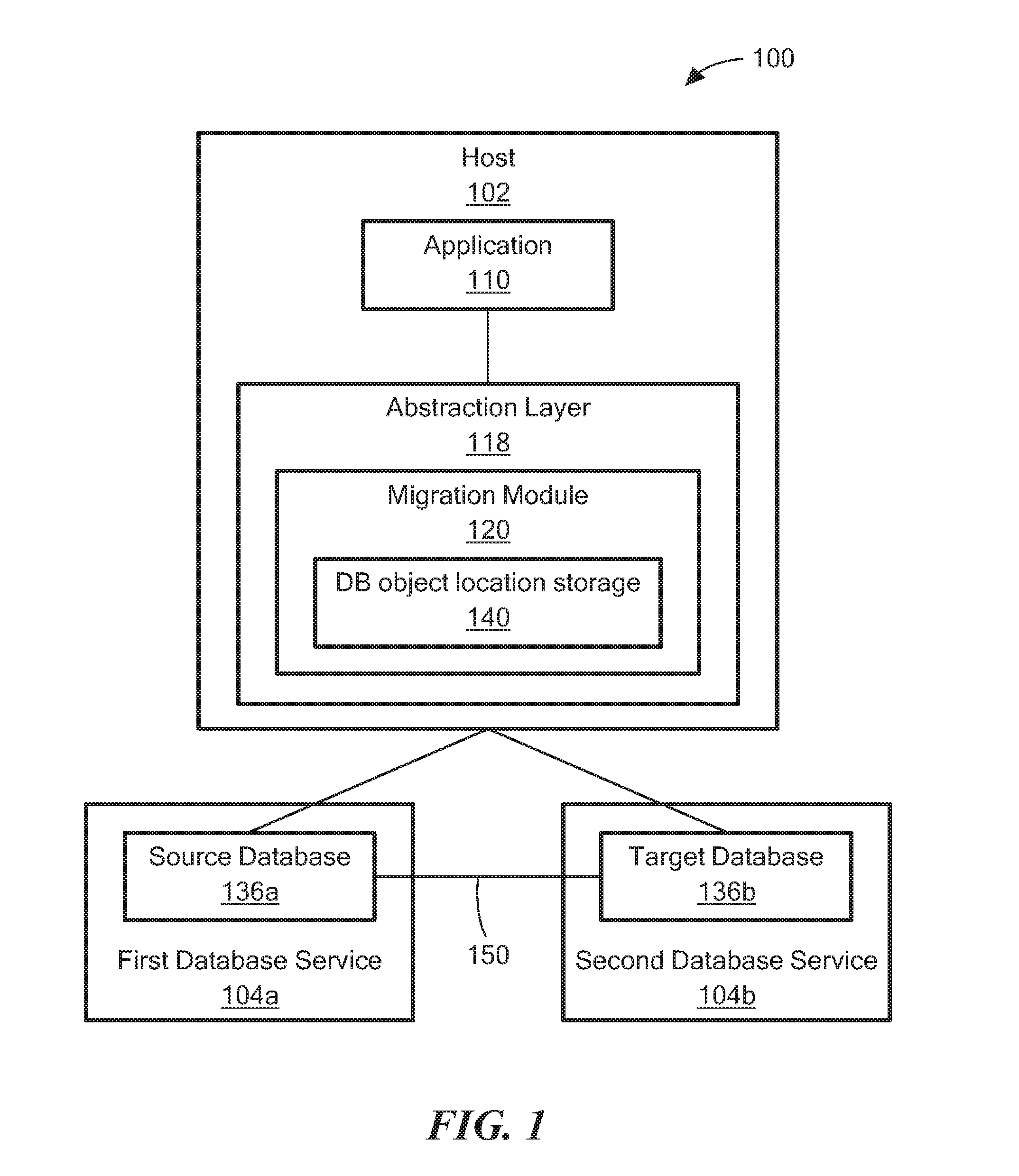
Referring to FIG. 1, a system 100 is an example of a system to migrate a database from one database service to another database service. In one example, the migration is from a first database service from a first cloud provider to a second database service from a second cloud provider. In other examples, the migration may be between databases services provided by the same cloud provider.
System 100 includes a host 102, a first database service 104a (e.g., DBaaS), and a second database service 104b (e.g., DBaaS). The host 102 includes an application 110 and an abstraction layer 118 (e.g., a database connectivity abstraction layer) that includes a migration module 120. The first database service 104a includes a source database service 136a and the second database 104b includes a target database 136b. Before database migration the source database 136a has the database information (e.g., database objects) and none of the source database 136a has transferred to target database 136b. After database migration, the target database 136b has the data information and there is no data left at source database 136a. During database migration there is some data on the source database 136a and the target database 136b.
The migration module 120 includes DB object location storage 140 that records where DB objects are located (e.g., either the source database 136a or the target database 136b).
A communications link 150 ties the source database 136a to the target database 136b. As will be further described herein either the source database 136a is accessed directly by the abstraction layer 118 or the target database 136b is accessed directly by the abstraction layer 118. However, in either case, during migration, data may be required to be accessed from both locations. The communication link 150 is used to ensure access of the data required regardless of where it is located and regardless of what database (source or target) is accessed directly.
As will be further described herein the migration module 120 intercepts messages (e.g., database commands using SQL, for example) from the application 110. The application 110 does not know that the migration module 120 is actually sending the messages to either a source database 136a or a target database 136b depending on the database migration.
Referring to FIG. 2, a process 200 is an example of a process to migrate a DB from one database service to another database service. Process 200 forms a communications link in the source database (202). For example, the migration module 120 establishes a communication link with the source database 136a.
Process 200 moves DB objects from the source database to the target database (206). For example, the migration module 120 moves database objects from the source database 136a to the target database 136b. In one example, a DB object is a table. In another example, the DB object is a character large object (CLOB).
Process 200 records the location of the DB objects at target database (210). For example, for each DB object that has been moved to the target database 136b, the migration module 120 records in the DB object location storage 140 that the DB object is now in the target database 136b. Thus, when the application 110 sends a database command that relates to a DB object on the target database 136b, the migration module 120, after checking the DB object location storage 140, routes the database command to the target database 136b. Furthermore, when an application 110 views from the source database 136a a DB object that has already been migrated a pointer will be used to point to the target database 136b to view the DB object.
Referring to FIG. 3, a process 300 is an example of a process to use a target database after the process 200 has initiated. For example, process 300 is started after a majority of the DB object have transferred from the source database 136a to the target database 136b. While the process 300 is an example of directly accessing the target database 136b after process 200 has initiated, one of ordinary skill in the art would recognize that the techniques of process 300 may be applied to the example of accessing the source database 136a directly until after the migration is complete.
Process 300 generates a communications link in the target database (303). For example, the communications link 150 is established between the source database 136a and the target database 136b. Process 300 moves DB objects to the target database (310) and records the DB object now at the target database (318). For example, for each DB object that has been moved to the target database 136b, the migration module 120 records in the DB object location storage 140 that the DB object is now in the target database 136b. Thus, when the application 110 sends a database command that relates to a DB object on the target database 136b, the migration module 120, after checking the DB object location storage 140, routes the database command to the target database 136b.
Process 300 establishes remote access to enable access to DB objects at the source database (320). For example, if directly accessing the target base 136b some DB objects may not have migrated to the target database 136b yet. Remote access is used to access the source database through the communications link to access objects at the source database. In one particular example, relational databases use SQL commands, which may use a join command, for example, that involves multiple database tables. That is, the SQL command may include more than one DB object and each DB needs to be directed to the database that includes the DB object. For example, an SQL command will arrive that needs access to tables from the source database 136a and the target database 136b. In one example, an SQL synonym command is used to establish remote access to DB objects at the source database. In one particular example, an Emp(employee) table may be in the source database 136a and Dept(department) table may be in the target database. Then a synonym command is generated such as a command: synonym to emp using the communications link 150 from the target database 136b to the source database 136a. In one particular example, process 300 may be modified so that either the target database or the source database may be accessed directly depending on how many DB objects have been migrated using the DB object location storage 140. In another particular example, process 300 may be modified so that either the target database 136b or the source database 136a may be accessed depending on where the DB objects are for a particular command (e.g., join command). For example, if all or a majority of the DB objects are at the target database, then the target database is accessed.
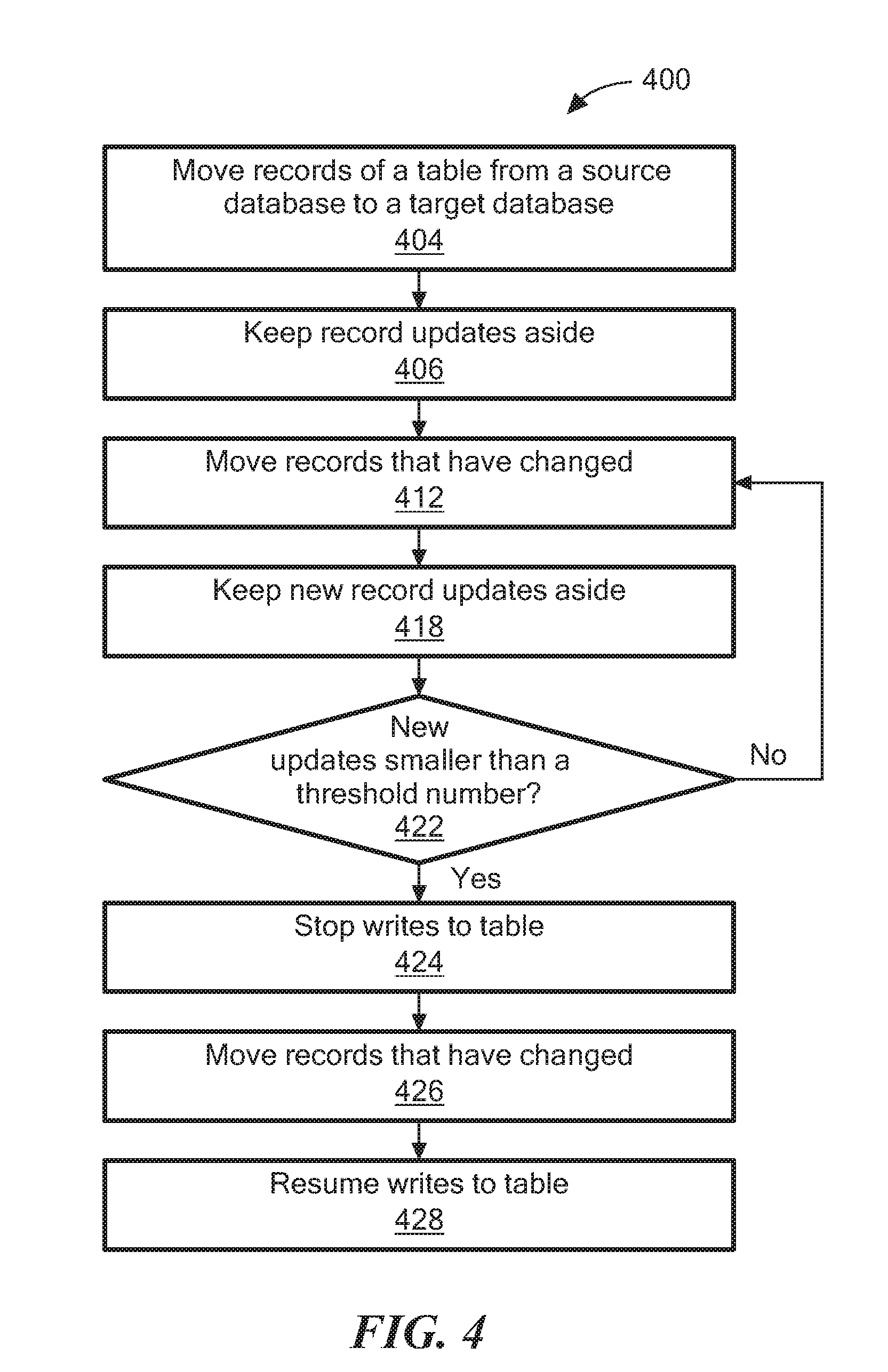
Referring to FIG. 4, a process 400 is an example of a process to move a single table from one database service to another database service. In particular, process 400 maintains data consistency but there is no downtime for the user waiting for the migration of the database to be completed.
Process 400 moves records of a table from a source database to a target database (404). For example, the migration module 120 move the records from of a table from the source database 136a to the target database 136.
Process 400 keeps updates aside (406). For example, the migration module 120 keeps updates (e.g., changes) to the records and they are not applied to the table at the target database 136b. In one example, the updates are kept at the source database 136a in parallel.
Process 400 move records that have changed (412). For example, the records that have changed are moved to the target database 136b.
Process 400 keeps new updates aside (418). For example, processing block 418 is the same as processing block 422.
Process 400 determines if the number of new updates is smaller than a threshold number (422). If the number of new updates is smaller than a threshold number, then process 400 stops writes to the table (424), move the records that have changed (426) and resumes writes to the table (428).
If the number of new updates is not smaller than a threshold number, then process 400 repeats processing blocks 412, 418 and 422.
In other examples, process 400 may be replaced with a process that will stop writes to the table. For example, the migration module 120, which intercepts command messages (e.g., SQLs), parses the command messages to identify which tables are being written to and holds these command messages from writing to a table being migrated until the migration of the table has completed.
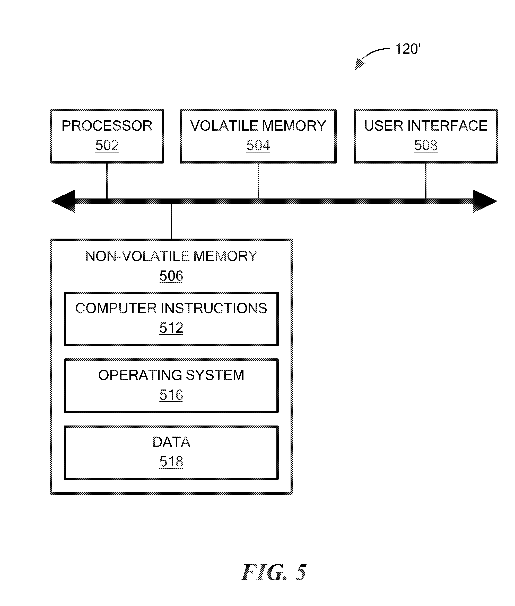
Referring to FIG. 5, in one example, a migration module 120 is a migration module 120'. The migration module 120' includes a processor 502, a volatile memory 504, a non-volatile memory 506 (e.g., hard disk) and the user interface (UI) 508 (e.g., a graphical user interface, a mouse, a keyboard, a display, touch screen and so forth). The non-volatile memory 506 stores computer instructions 512, an operating system 516 and data 518. In one example, the computer instructions 512 are executed by the processor 502 out of volatile memory 504 to perform all or part of the processes described herein (e.g., processes 200, 300 and 400).
The processes described herein (e.g., process processes 200, 300 and 400) are not limited to use with the hardware and software of FIG. 5; they may find applicability in any computing or processing environment and with any type of machine or set of machines that is capable of running a computer program. The processes described herein may be implemented in hardware, software, or a combination of the two. The processes described herein may be implemented in computer programs executed on programmable computers/machines that each includes a processor, a non-transitory machine-readable medium or other article of manufacture that is readable by the processor (including volatile and non-volatile memory and/or storage elements), at least one input device, and one or more output devices. Program code may be applied to data entered using an input device to perform any of the processes described herein and to generate output information.
The system may be implemented, at least in part, via a computer program product, (e.g., in a non-transitory machine-readable storage medium such as, for example, a non-transitory computer-readable medium), for execution by, or to control the operation of, data processing apparatus (e.g., a programmable processor, a computer, or multiple computers)). Each such program may be implemented in a high level procedural or object-oriented programming language to communicate with a computer system. However, the programs may be implemented in assembly or machine language. The language may be a compiled or an interpreted language and it may be deployed in any form, including as a stand-alone program or as a module, component, subroutine, or other unit suitable for use in a computing environment. A computer program may be deployed to be executed on one computer or on multiple computers at one site or distributed across multiple sites and interconnected by a communication network. A computer program may be stored on a non-transitory machine-readable medium that is readable by a general or special purpose programmable computer for configuring and operating the computer when the non-transitory machine-readable medium is read by the computer to perform the processes described herein. For example, the processes described herein may also be implemented as a non-transitory machine-readable storage medium, configured with a computer program, where upon execution, instructions in the computer program cause the computer to operate in accordance with the processes. A non-transitory machine-readable medium may include but is not limited to a hard drive, compact disc, flash memory, non-volatile memory, volatile memory, magnetic diskette and so forth but does not include a transitory signal per se.
The processes described herein are not limited to the specific examples described. For example, the processes 200, 300 and 400 are not limited to the specific processing order of FIGS. 2 to 4, respectively. Rather, any of the processing blocks of FIGS. 2 to 4 may be re-ordered, combined or removed, performed in parallel or in serial, as necessary, to achieve the results set forth above.
The processing blocks (for example, in the processes 200, 300 and 400) associated with implementing the system may be performed by one or more programmable processors executing one or more computer programs to perform the functions of the system. All or part of the system may be implemented as, special purpose logic circuitry (e.g., an FPGA (field-programmable gate array) and/or an ASIC (application-specific integrated circuit)). All or part of the system may be implemented using electronic hardware circuitry that include electronic devices such as, for example, at least one of a processor, a memory, a programmable logic device or a logic gate.
Elements of different embodiments described herein may be combined to form other embodiments not specifically set forth above. Other embodiments not specifically described herein are also within the scope of the following claims.
* * * * *
D00000
D00001
D00002
D00003
D00004
XML
uspto.report is an independent third-party trademark research tool that is not affiliated, endorsed, or sponsored by the United States Patent and Trademark Office (USPTO) or any other governmental organization. The information provided by uspto.report is based on publicly available data at the time of writing and is intended for informational purposes only.
While we strive to provide accurate and up-to-date information, we do not guarantee the accuracy, completeness, reliability, or suitability of the information displayed on this site. The use of this site is at your own risk. Any reliance you place on such information is therefore strictly at your own risk.
All official trademark data, including owner information, should be verified by visiting the official USPTO website at www.uspto.gov. This site is not intended to replace professional legal advice and should not be used as a substitute for consulting with a legal professional who is knowledgeable about trademark law.