Lens assembly
Chen , et al. Sept
U.S. patent number 10,409,033 [Application Number 15/822,422] was granted by the patent office on 2019-09-10 for lens assembly. This patent grant is currently assigned to ASIA OPTICAL CO., INC., SINTAI OPTICAL (SHENZHEN) CO., LTD.. The grantee listed for this patent is Asia Optical Co., Inc., Sintai Optical (Shenzhen) Co., Ltd.. Invention is credited to Hsi-Ling Chang, Chien-Hung Chen.


View All Diagrams
| United States Patent | 10,409,033 |
| Chen , et al. | September 10, 2019 |
Lens assembly
Abstract
A lens assembly includes a first lens, a second lens, a third lens, and a fourth lens, wherein the first lens, the second lens, the third lens, and the fourth lens are arranged in order from an object side to an image side along an optical axis. The first lens is with positive refractive power. The second lens is with negative refractive power. The third lens is with refractive power. The fourth lens is with negative refractive power. The lens assembly satisfies: 0.2<D.sub.4/TTL<0.6, wherein D.sub.4 is an effective diameter of the fourth lens and TTL is an interval from an object side surface of the first lens to an image plane along the optical axis.
| Inventors: | Chen; Chien-Hung (Taichung, TW), Chang; Hsi-Ling (Taichung, TW) | ||||||||||
|---|---|---|---|---|---|---|---|---|---|---|---|
| Applicant: |
|
||||||||||
| Assignee: | SINTAI OPTICAL (SHENZHEN) CO.,
LTD. (Shenzhen, CN) ASIA OPTICAL CO., INC. (Taichung, TW) |
||||||||||
| Family ID: | 65517877 | ||||||||||
| Appl. No.: | 15/822,422 | ||||||||||
| Filed: | November 27, 2017 |
Prior Publication Data
| Document Identifier | Publication Date | |
|---|---|---|
| US 20190072745 A1 | Mar 7, 2019 | |
Foreign Application Priority Data
| Sep 6, 2017 [CN] | 2017 1 0797110 | |||
| Current U.S. Class: | 1/1 |
| Current CPC Class: | G02B 9/60 (20130101); G02B 13/004 (20130101); G02B 9/34 (20130101) |
| Current International Class: | G02B 3/02 (20060101); G02B 9/34 (20060101); G02B 13/00 (20060101); G02B 9/60 (20060101) |
| Field of Search: | ;359/714 |
References Cited [Referenced By]
U.S. Patent Documents
| 9933602 | April 2018 | Li |
| 2012/0194920 | August 2012 | Huang |
| 2016/0011398 | January 2016 | Tsai |
Attorney, Agent or Firm: McClure, Qualey, & Rodack, LLP
Claims
What is claimed is:
1. A lens assembly comprising: a first lens which is with positive refractive power; a second lens which is with negative refractive power; a third lens which is with refractive power; and a fourth lens which is with negative refractive power; wherein the first lens, the second lens, the third lens, and the fourth lens are arranged in order from an object side to an image side along an optical axis; wherein the lens assembly satisfies: 0.2<D.sub.4/TTL<0.6, wherein D.sub.4 is an effective diameter of the fourth lens and TTL is an interval from an object side surface of the first lens to an image plane along the optical axis.
2. The lens assembly as claimed in claim 1, further comprising a fifth lens disposed between the third lens and the fourth lens, wherein the fifth lens is with positive refractive power.
3. The lens assembly as claimed in claim 1, wherein the lens assembly satisfies: f.sub.234<0, wherein f.sub.234 is an effective focal length of a combination of the second lens, the third lens, and the fourth lens.
4. The lens assembly as claimed in claim 1, wherein the lens assembly satisfies: TC.sub.34<TTL/5, wherein TC.sub.34 is an air interval from an image side surface of the third lens to an object side surface of the fourth lens along the optical axis and TTL is an interval from an object side surface of the first lens to an image plane along the optical axis.
5. The lens assembly as claimed in claim 1, wherein the lens assembly satisfies: R.sub.41/R.sub.11<0, wherein R.sub.11 is a radius of curvature of an object side surface of the first lens and R.sub.41 is a radius of curvature of an object side surface of the fourth lens.
6. The lens assembly as claimed in claim 1, wherein the lens assembly satisfies: (f.sub.1+f.sub.3)/f.sub.2<0, wherein f.sub.1 is an effective focal length of the first lens, f.sub.2 is an effective focal length of the second lens, and f.sub.3 is an effective focal length of the third lens.
7. The lens assembly as claimed in claim 1, wherein the lens assembly satisfies: TC.sub.23<TTL/5, wherein TC.sub.23 is an air interval from an image side surface of the second lens to an object side surface of the third lens along the optical axis and TTL is an interval from an object side surface of the first lens to an image plane along the optical axis.
8. The lens assembly as claimed in claim 1, further comprising a stop disposed between the object side and the second lens, wherein the lens assembly satisfies: 0.6<SL/TTL<1.1, wherein SL is an interval from the stop to an image plane along the optical axis and TTL is an interval from an object side surface of the first lens to the image plane along the optical axis.
9. The lens assembly as claimed in claim 1, further comprising a non-circular stop, wherein the non-circular stop comprises an outer circumferential portion and an inner circumferential portion, at least one of the outer circumferential portion and the inner circumferential portion is non-circular, the inner circumferential portion surrounds the optical axis to form a hole, and the non-circular stop satisfies: 1<Dx/Dy<28, wherein Dx is a maximum dimension of the hole through which the optical axis passes and Dy is a minimum dimension of the hole through which the optical axis passes.
10. The lens assembly as claimed in claim 2, wherein the lens assembly satisfies: f.sub.2354<0, wherein f.sub.2354 is an effective focal length of a combination of the second lens, the third lens, the fifth lens, and the fourth lens.
11. The lens assembly as claimed in claim 1, wherein the lens assembly satisfies: 0.07<(TC.sub.12+TC.sub.23)/TTL<0.25, wherein TC.sub.12 is an air interval from an image side surface of the first lens to an object side surface of the second lens along the optical axis, TC.sub.23 is an air interval from an image side surface of the second lens to an object side surface of the third lens along the optical axis, and TTL is an interval from an object side surface of the first lens to an image plane along the optical axis.
12. A lens assembly comprising: a first lens which is with positive refractive power; a second lens which is with negative refractive power; a third lens which is with refractive power; and a fourth lens which is with negative refractive power; wherein the first lens, the second lens, the third lens, and the fourth lens are arranged in order from an object side to an image side along an optical axis; wherein the lens assembly satisfies: 0.07<(TC.sub.12+TC.sub.23)/TTL<0.25, wherein TC.sub.12 is an air interval from an image side surface of the first lens to an object side surface of the second lens along the optical axis, TC.sub.23 is an air interval from an image side surface of the second lens to an object side surface of the third lens along the optical axis, and TTL is an interval from an object side surface of the first lens to an image plane along the optical axis.
13. The lens assembly as claimed in claim 12, further comprising a fifth lens disposed between the third lens and the fourth lens, wherein the fifth lens is with positive refractive power.
14. The lens assembly as claimed in claim 12, wherein the lens assembly satisfies: f.sub.234<0, wherein f.sub.234 is an effective focal length of a combination of the second lens, the third lens, and the fourth lens.
15. The lens assembly as claimed in claim 12, wherein the lens assembly satisfies: TC.sub.34<TTL/5, wherein TC.sub.34 is an air interval from an image side surface of the third lens to an object side surface of the fourth lens along the optical axis and TTL is an interval from an object side surface of the first lens to an image plane along the optical axis.
16. The lens assembly as claimed in claim 12, wherein the lens assembly satisfies: R.sub.41/R.sub.11<0, wherein R.sub.11 is a radius of curvature of an object side surface of the first lens and R.sub.41 is a radius of curvature of an object side surface of the fourth lens.
17. The lens assembly as claimed in claim 12, wherein the lens assembly satisfies: (f.sub.1+f.sub.3)/f.sub.2<0, wherein f.sub.1 is an effective focal length of the first lens, f.sub.2 is an effective focal length of the second lens, and f.sub.3 is an effective focal length of the third lens.
18. The lens assembly as claimed in claim 12, further comprising a stop disposed between the object side and the second lens, wherein the lens assembly satisfies: 0.6<SL/TTL<1.1, wherein SL is an interval from the stop to an image plane along the optical axis and TTL is an interval from an object side surface of the first lens to the image plane along the optical axis.
19. A lens assembly comprising: a first lens which is with positive refractive power; a second lens which is with negative refractive power; a third lens which is with refractive power; and a fourth lens which is with negative refractive power; wherein the first lens, the second lens, the third lens, and the fourth lens are arranged in order from an object side to an image side along an optical axis; wherein the lens assembly satisfies: 1<f/TTL.ltoreq.1.5, wherein f is an effective focal length of the lens assembly and TTL is an interval from an object side surface of the first lens to an image plane along the optical axis; wherein the lens assembly further comprises a non-circular stop, wherein the non-circular stop comprises an outer circumferential portion and an inner circumferential portion, at least one of the outer circumferential portion and the inner circumferential portion is non-circular, the inner circumferential portion surrounds the optical axis to form a hole, and the non-circular stop satisfies: 1<Dx/Dy<28, wherein Dx is a maximum dimension of the hole through which the optical axis passes and Dy is a minimum dimension of the hole through which the optical axis passes.
20. The lens assembly as claimed in claim 12, wherein the lens assembly satisfies: 1<f/TTL<1.5, wherein f is an effective focal length of the lens assembly and TTL is an interval from an object side surface of the first lens to an image plane along the optical axis.
Description
BACKGROUND OF THE INVENTION
Field of the Invention
The invention relates to a lens assembly.
Description of the Related Art
Nowadays, the development trend of a lens assembly is continuously toward miniaturization and high resolution. However, the known lens assembly can't satisfy such requirements. Therefore, the lens assembly needs a new structure in order to meet the requirements of miniaturization and high resolution at the same time.
BRIEF SUMMARY OF THE INVENTION
The invention provides a lens assembly to solve the above problems. The lens assembly of the invention is provided with characteristics of a shortened total lens length, a higher resolution, and still has a good optical performance.
The lens assembly in accordance with an exemplary embodiment of the invention includes a first lens, a second lens, a third lens, and a fourth lens, wherein the first lens, the second lens, the third lens, and the fourth lens are arranged in order from an object side to an image side along an optical axis. The first lens is with positive refractive power. The second lens is with negative refractive power. The third lens is with refractive power. The fourth lens is with negative refractive power. The lens assembly satisfies: 0.2<D.sub.4/TTL<0.6, wherein D.sub.4 is an effective diameter of the fourth lens and TTL is an interval from an object side surface of the first lens to an image plane along the optical axis.
In another exemplary embodiment, the lens assembly further includes a fifth lens disposed between the third lens and the fourth lens, wherein the fifth lens is with positive refractive power.
In yet another exemplary embodiment, the lens assembly satisfies: f.sub.234<0, wherein f.sub.234 is an effective focal length of a combination of the second lens, the third lens, and the fourth lens.
In another exemplary embodiment, the lens assembly satisfies: TC.sub.34<TTL/5, wherein TC.sub.34 is an air interval from an image side surface of the third lens to an object side surface of the fourth lens along the optical axis and TTL is an interval from an object side surface of the first lens to an image plane along the optical axis.
In yet another exemplary embodiment, the lens assembly satisfies: R.sub.41/R.sub.11<0, wherein R.sub.11 is a radius of curvature of an object side surface of the first lens and R.sub.41 is a radius of curvature of an object side surface of the fourth lens.
In another exemplary embodiment, the lens assembly satisfies: (f.sub.1+f.sub.3)/f.sub.2<0, wherein f.sub.1 is an effective focal length of the first lens, f.sub.2 is an effective focal length of the second lens, and f.sub.3 is an effective focal length of the third lens.
In yet another exemplary embodiment, the lens assembly satisfies: TC.sub.23<TTL/5, wherein TC.sub.23 is an air interval from an image side surface of the second lens to an object side surface of the third lens along the optical axis and TTL is an interval from an object side surface of the first lens to an image plane along the optical axis.
In another exemplary embodiment, the lens assembly further includes a stop disposed between the object side and the second lens, wherein the lens assembly satisfies: 0.6<SL/TTL<1.1, wherein SL is an interval from the stop to an image plane along the optical axis and TTL is an interval from an object side surface of the first lens to the image plane along the optical axis.
In yet another exemplary embodiment, the lens assembly further includes a non-circular stop, wherein the non-circular stop includes an outer circumferential portion and an inner circumferential portion, at least one of the outer circumferential portion and the inner circumferential portion is non-circular, the inner circumferential portion surrounds the optical axis to form a hole, and the non-circular stop satisfies: 1<Dx/Dy<28, wherein Dx is a maximum dimension of the hole through which the optical axis passes and Dy is a minimum dimension of the hole through which the optical axis passes.
In another exemplary embodiment, the lens assembly satisfies: f.sub.2354<0, wherein f.sub.2354 is an effective focal length of a combination of the second lens, the third lens, the fifth lens, and the fourth lens.
In yet another exemplary embodiment, the lens assembly satisfies: 0.07<(TC.sub.12+TC.sub.23)/TTL<0.25, wherein TC.sub.12 is an air interval from an image side surface of the first lens to an object side surface of the second lens along the optical axis, TC.sub.23 is an air interval from an image side surface of the second lens to an object side surface of the third lens along the optical axis, and TTL is an interval from an object side surface of the first lens to an image plane along the optical axis.
The lens assembly in accordance with an exemplary embodiment of the invention includes a first lens, a second lens, a third lens, and a fourth lens, wherein the first lens, the second lens, the third lens, and the fourth lens are arranged in order from an object side to an image side along an optical axis. The first lens is with positive refractive power. The second lens is with negative refractive power. The third lens is with refractive power. The fourth lens is with negative refractive power. The lens assembly satisfies: 1<f/TTL<1.5, wherein f is an effective focal length of the lens assembly and TTL is an interval from an object side surface of the first lens to an image plane along the optical axis.
In another exemplary embodiment, the lens assembly further includes a fifth lens disposed between the third lens and the fourth lens, wherein the fifth lens is with positive refractive power.
In yet another exemplary embodiment, the lens assembly satisfies: f.sub.234<0, wherein f.sub.234 is an effective focal length of a combination of the second lens, the third lens, and the fourth lens.
In another exemplary embodiment, the lens assembly satisfies: TC.sub.34<TTL/5, wherein TC.sub.34 is an air interval from an image side surface of the third lens to an object side surface of the fourth lens along the optical axis and TTL is an interval from an object side surface of the first lens to an image plane along the optical axis.
In yet another exemplary embodiment, the lens assembly satisfies: R.sub.41/R.sub.11<0, wherein R.sub.11 is a radius of curvature of an object side surface of the first lens and R.sub.41 is a radius of curvature of an object side surface of the fourth lens.
In another exemplary embodiment, the lens assembly satisfies: (f.sub.1+f.sub.3)/f.sub.2<0, wherein f.sub.1 is an effective focal length of the first lens, f.sub.2 is an effective focal length of the second lens, and f.sub.3 is an effective focal length of the third lens.
In yet another exemplary embodiment, the lens assembly further includes a stop disposed between the object side and the second lens, wherein the lens assembly satisfies: 0.6<SL/TTL<1.1, wherein SL is an interval from the stop to an image plane along the optical axis and TTL is an interval from an object side surface of the first lens to the image plane along the optical axis.
In another exemplary embodiment, the lens assembly further includes a non-circular stop, wherein the non-circular stop includes an outer circumferential portion and an inner circumferential portion, at least one of the outer circumferential portion and the inner circumferential portion is non-circular, the inner circumferential portion surrounds the optical axis to form a hole, and the non-circular stop satisfies: 1<Dx/Dy<28, wherein Dx is a maximum dimension of the hole through which the optical axis passes and Dy is a minimum dimension of the hole through which the optical axis passes.
In yet another exemplary embodiment, the lens assembly satisfies: 0.07<(TC.sub.12+TC.sub.23)/TTL<0.25, wherein TC.sub.12 is an air interval from an image side surface of the first lens to an object side surface of the second lens along the optical axis, TC.sub.23 is an air interval from an image side surface of the second lens to an object side surface of the third lens along the optical axis, and TTL is an interval from an object side surface of the first lens to an image plane along the optical axis.
A detailed description is given in the following embodiments with reference to the accompanying drawings.
BRIEF DESCRIPTION OF THE DRAWINGS
The invention can be more fully understood by reading the subsequent detailed description and examples with references made to the accompanying drawings, wherein:
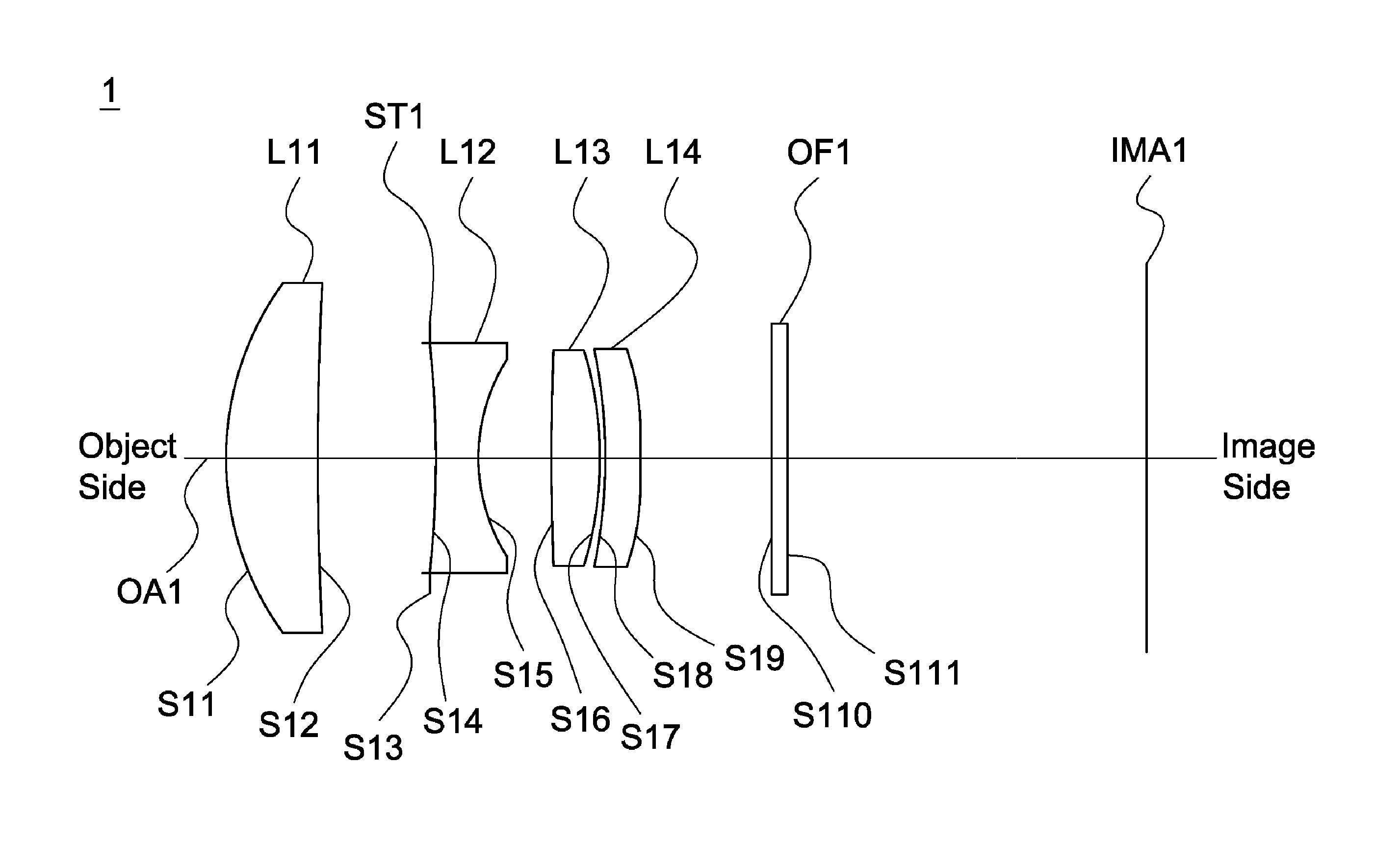
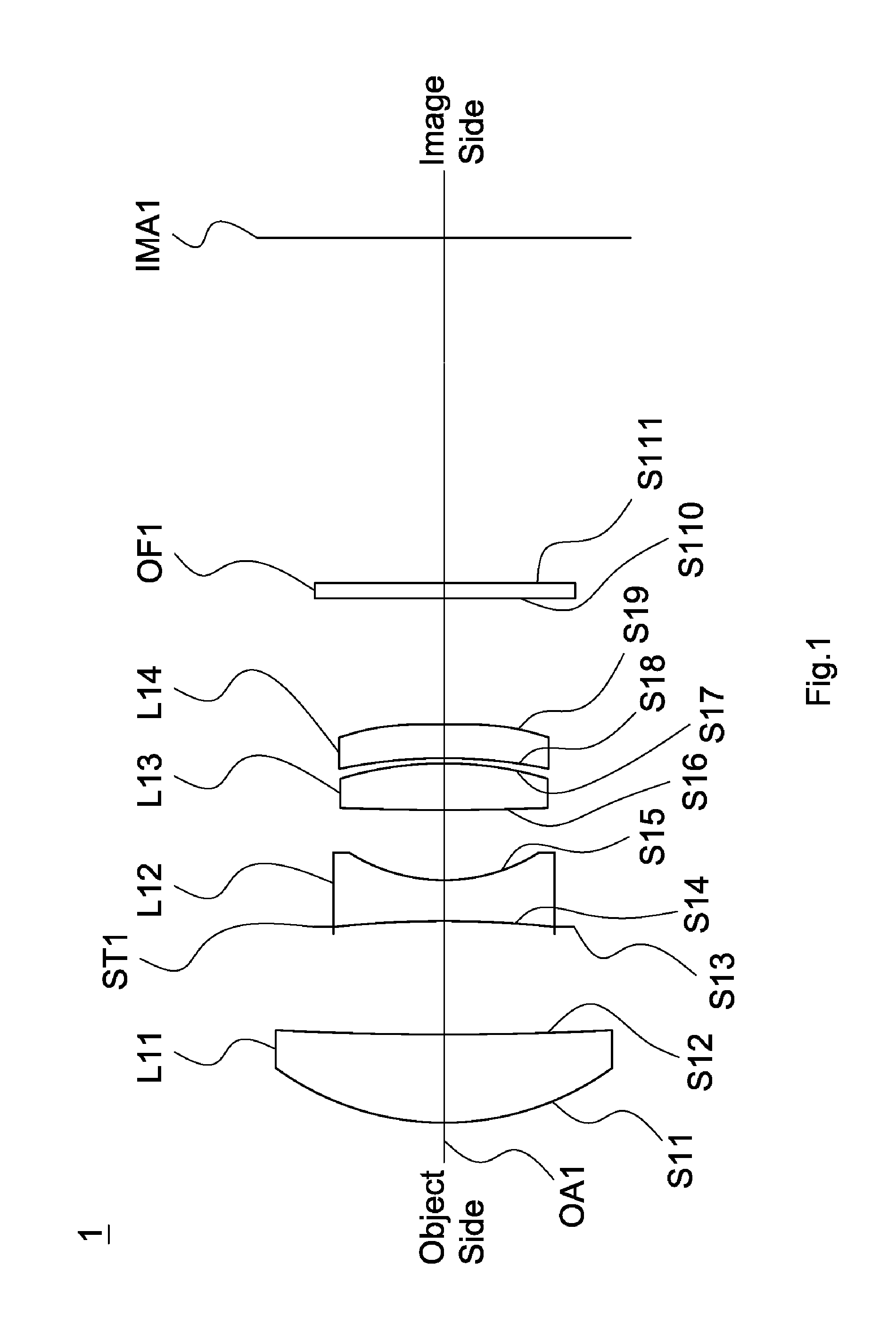
FIG. 1 is a lens layout diagram of a lens assembly in accordance with a first embodiment of the invention;
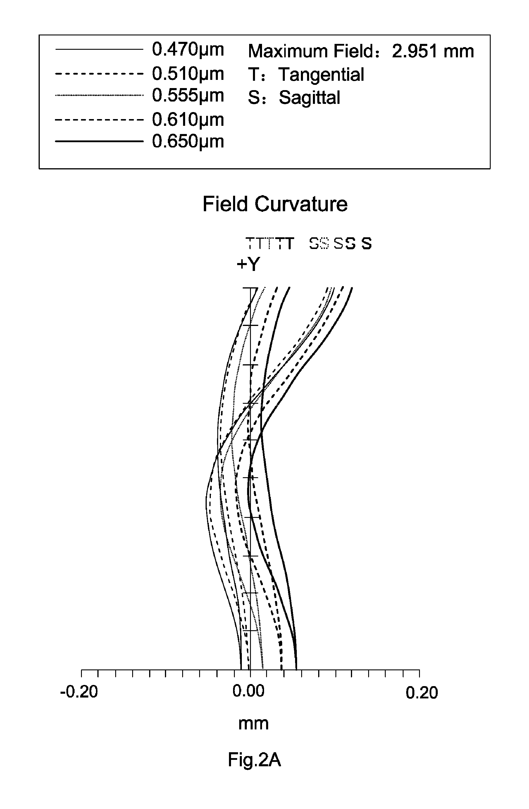
FIG. 2A depicts a field curvature diagram of the lens assembly in accordance with the first embodiment of the invention;
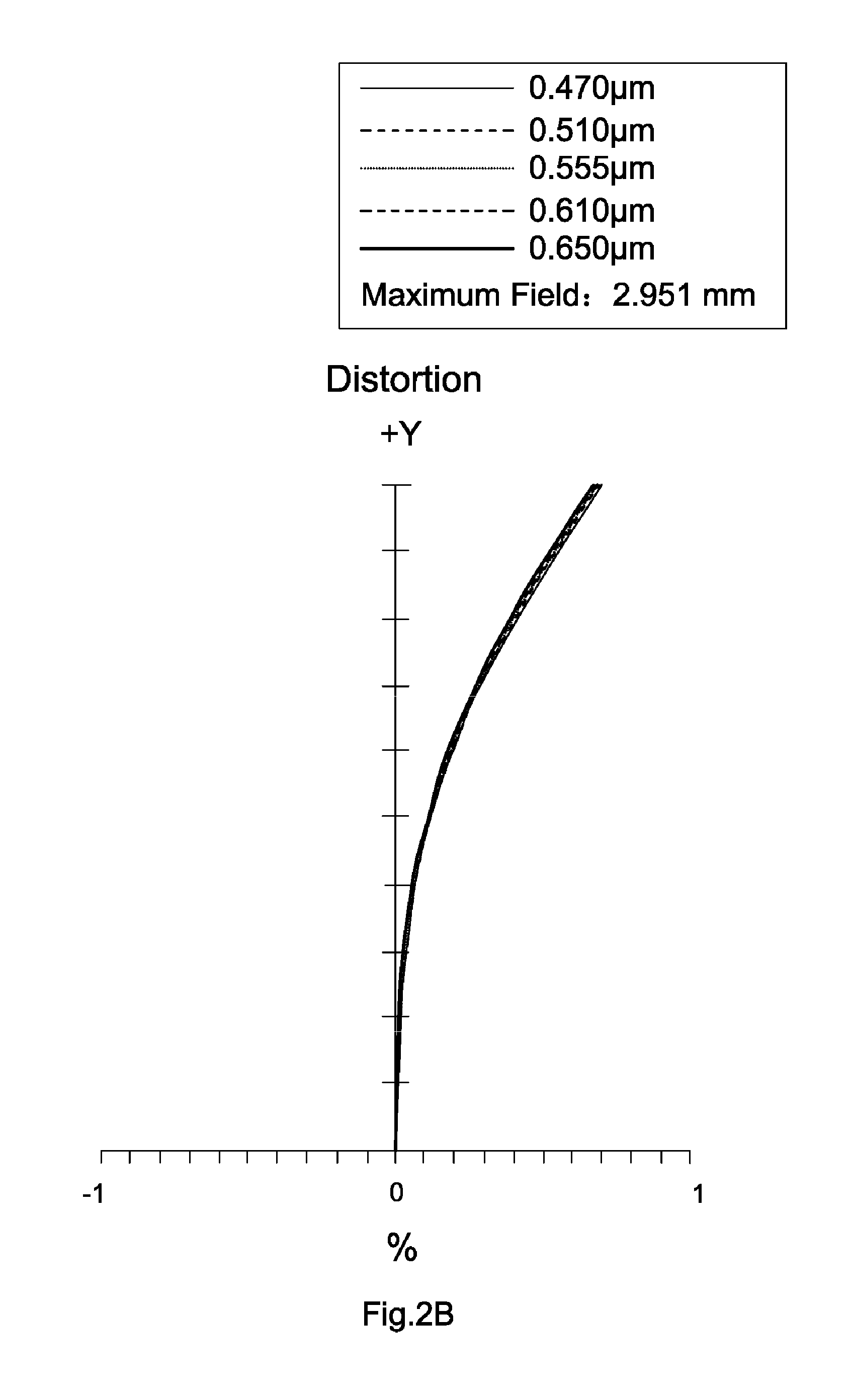
FIG. 2B is a distortion diagram of the lens assembly in accordance with the first embodiment of the invention;
FIG. 2C is a modulation transfer function diagram of the lens assembly in accordance with the first embodiment of the invention;
FIG. 3 is a lens layout diagram of a lens assembly in accordance with a third embodiment of the invention;
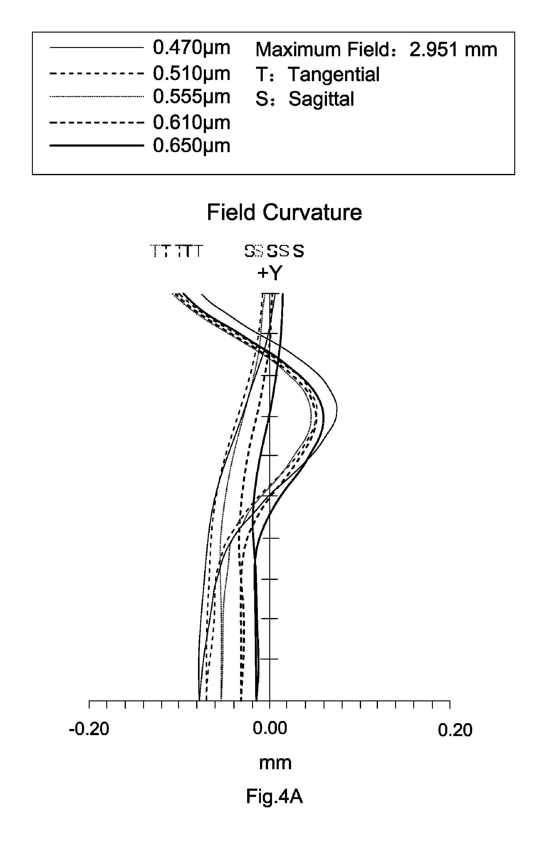
FIG. 4A depicts a field curvature diagram of the lens assembly in accordance with the third embodiment of the invention;
FIG. 4B is a distortion diagram of the lens assembly in accordance with the third embodiment of the invention;
FIG. 4C is a modulation transfer function diagram of the lens assembly in accordance with the third embodiment of the invention;
FIG. 5 is a lens layout diagram of a lens assembly in accordance with a fourth embodiment of the invention;
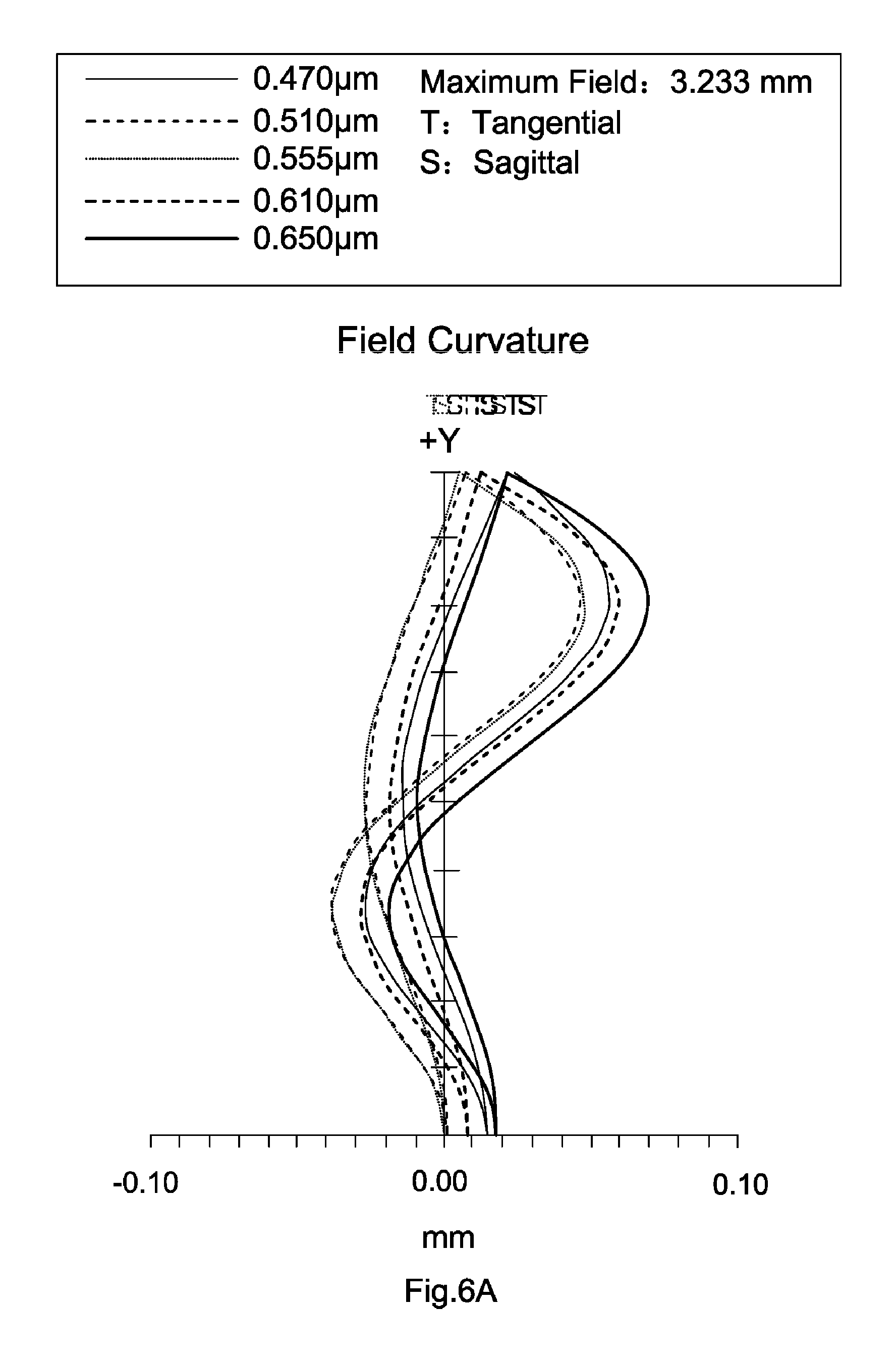
FIG. 6A depicts a field curvature diagram of the lens assembly in accordance with the fourth embodiment of the invention;
FIG. 6B is a distortion diagram of the lens assembly in accordance with the fourth embodiment of the invention;
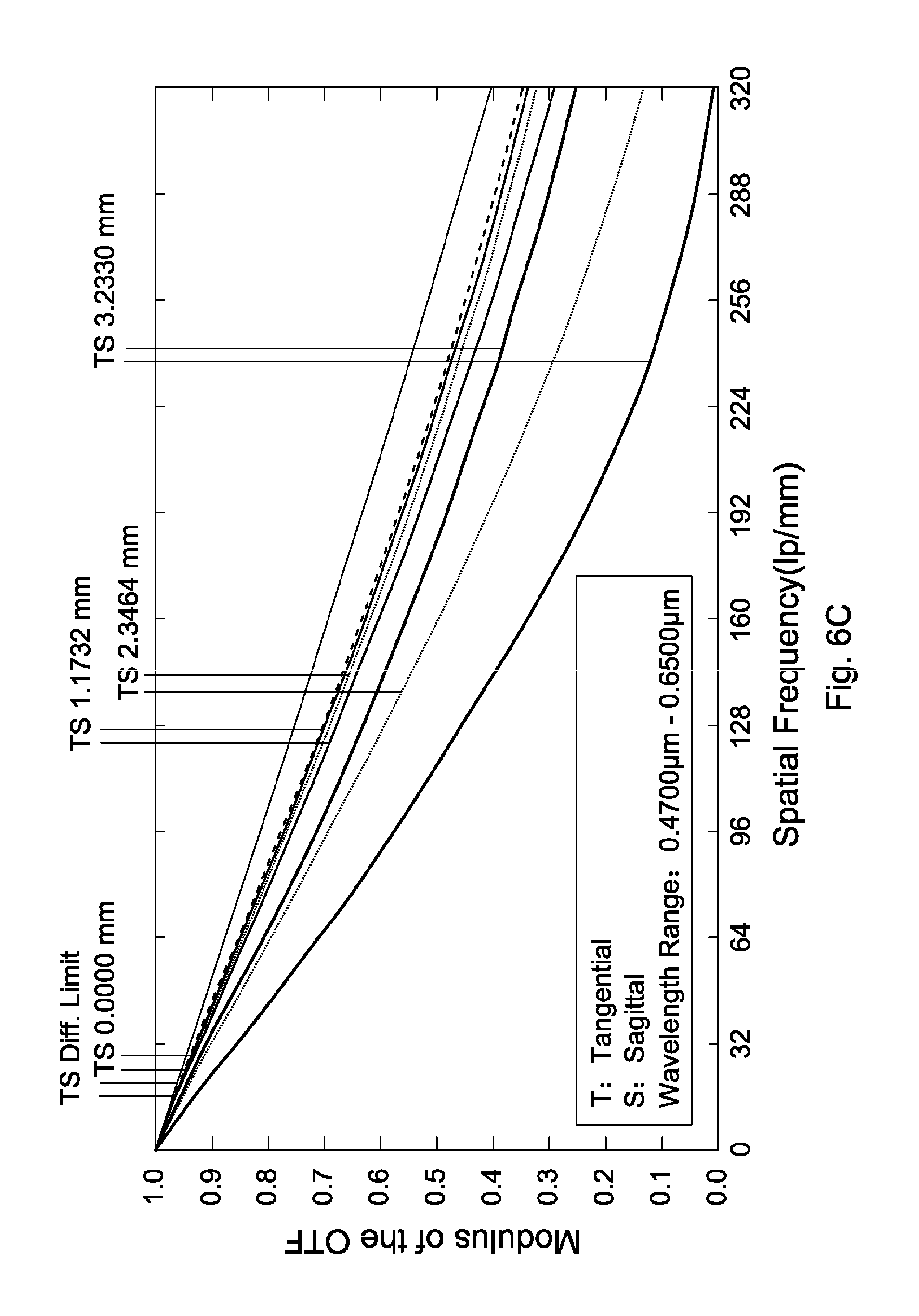
FIG. 6C is a modulation transfer function diagram of the lens assembly in accordance with the fourth embodiment of the invention;
FIG. 7 is a lens layout diagram of a lens assembly in accordance with a fifth embodiment of the invention;
FIG. 8A depicts a field curvature diagram of the lens assembly in accordance with the fifth embodiment of the invention;
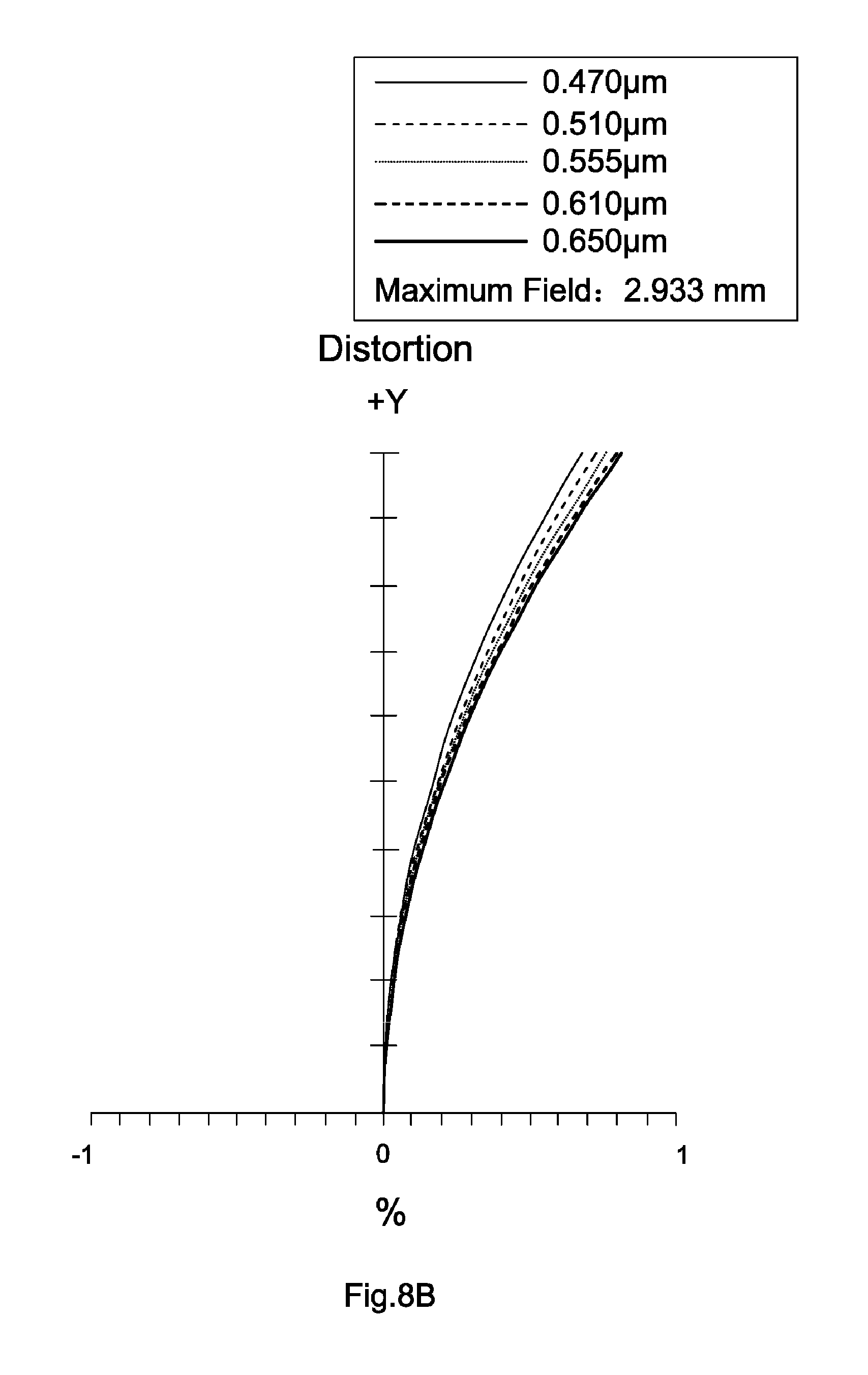
FIG. 8B is a distortion diagram of the lens assembly in accordance with the fifth embodiment of the invention;
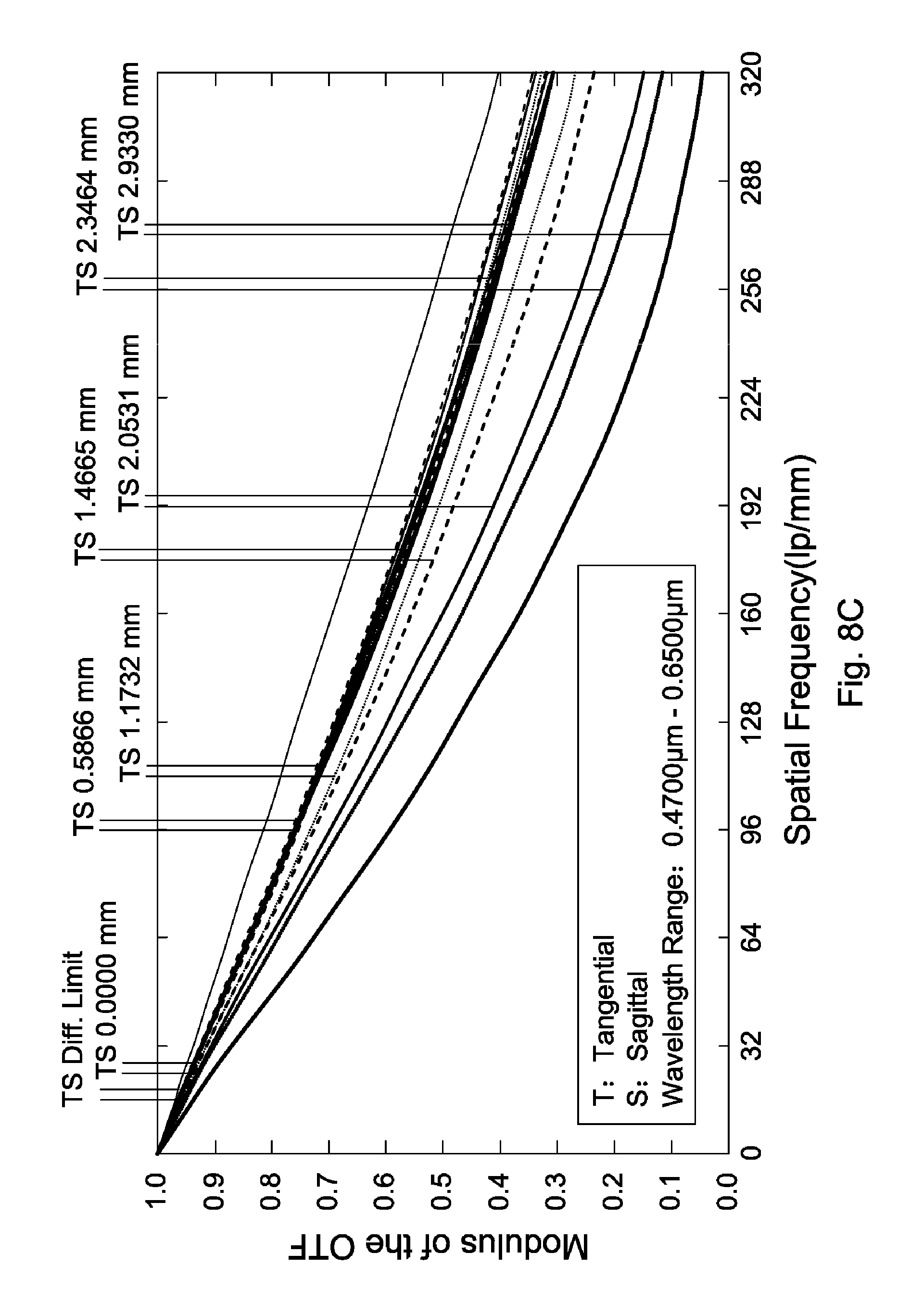
FIG. 8C is a modulation transfer function diagram of the lens assembly in accordance with the fifth embodiment of the invention;
FIG. 9 is a lens layout diagram of a lens assembly in accordance with a sixth embodiment of the invention;
FIG. 10A depicts a field curvature diagram of the lens assembly in accordance with the sixth embodiment of the invention;
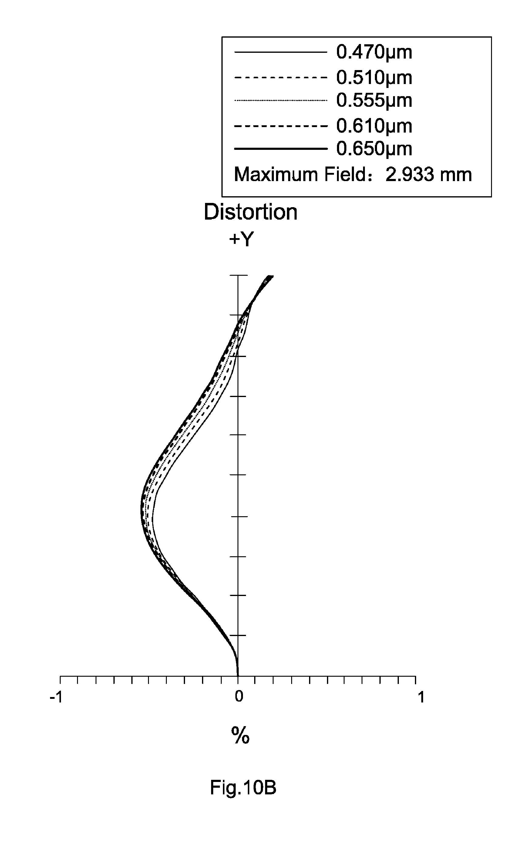
FIG. 10B is a distortion diagram of the lens assembly in accordance with the sixth embodiment of the invention;
FIG. 10C is a modulation transfer function diagram of the lens assembly in accordance with the sixth embodiment of the invention;
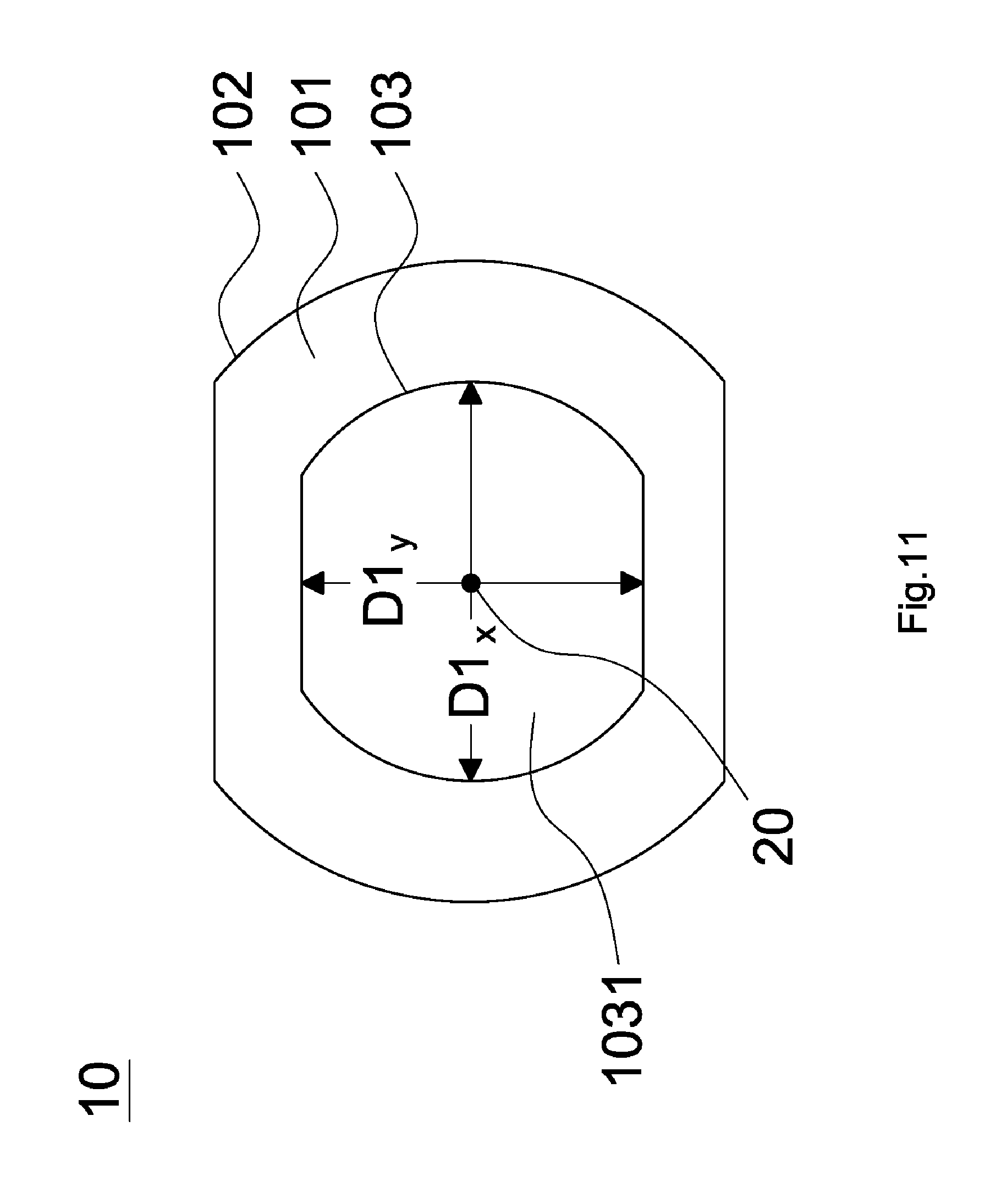
FIG. 11 depicts a non-circular stop in accordance with the invention; and
FIG. 12 depicts a non-circular stop in accordance with the invention.
DETAILED DESCRIPTION OF THE INVENTION
The following description is made for the purpose of illustrating the general principles of the invention and should not be taken in a limiting sense. The scope of the invention is best determined by reference to the appended claims.
Referring to FIG. 1, FIG. 1 is a lens layout diagram of a lens assembly in accordance with a first embodiment of the invention. The lens assembly 1 includes a first lens L11, a stop ST1, a second lens L12, a third lens L13, a fourth lens L14, and an optical filter OF1, all of which are arranged in order from an object side to an image side along an optical axis OA1. In operation, an image of light rays from the object side is formed at an image plane IMA1.
The first lens L11 is a meniscus lens with positive refractive power and made of glass material, wherein the object side surface S11 is a convex surface, the image side surface S12 is a concave surface, and both of the object side surface S11 and image side surface S12 are aspheric surfaces.
The second lens L12 is a biconcave lens with negative refractive power and made of glass material, wherein the object side surface S14 is a concave surface, the image side surface S15 is a concave surface, and both of the object side surface S14 and image side surface S15 are aspheric surfaces.
The third lens L13 is a biconvex lens with positive refractive power and made of glass material, wherein the object side surface S16 is a convex surface, the image side surface S17 is a convex surface, and both of the object side surface S16 and image side surface S17 are aspheric surfaces.
The fourth lens L14 is a meniscus lens with negative refractive power and made of glass material, wherein the object side surface S18 is a concave surface, the image side surface S19 is a convex surface, and both of the object side surface S18 and image side surface S19 are aspheric surfaces.
Both of the object side surface S110 and image side surface S111 of the optical filter OF1 are plane surfaces.
In order to maintain excellent optical performance of the lens assembly in accordance with the first embodiment of the invention, the lens assembly 1 satisfies at least one of the following conditions: R1.sub.41/R1.sub.11<0 (1) (f1.sub.1+f1.sub.3)/f1.sub.2<0 (2) f1.sub.234<0 (3) TC1.sub.23<TTL1/5 (4) TC1.sub.34<TTL1/5 (5) 0.6<SL1/TTL1<1.1 (6) 0.2<D1.sub.4/TTL1<0.6 (7) 1<f1/TTL1<1.5 (8) 0.07<(TC1.sub.12+TC1.sub.23)/TTL1<0.25 (9)
wherein R1.sub.11 is a radius of curvature of the object side surface S11 of the first lens L11, R1.sub.41 is a radius of curvature of the object side surface S18 of the fourth lens L14, f1.sub.1 is an effective focal length of the first lens L11, f1.sub.2 is an effective focal length of the second lens L12, f1.sub.3 is an effective focal length of the third lens L13, f1.sub.234 is an effective focal length of a combination of the second lens L12, the third lens L13, and the fourth lens L14, TC1.sub.23 is an air interval from the image side surface S15 of the second lens L12 to the object side surface S16 of the third lens L13 along the optical axis OA1, TTL1 is an interval from the object surface S11 of the first lens L11 to the image plane IMA1 along the optical axis OA1, TC1.sub.34 is an air interval from the image side surface S17 of the third lens L13 to the object side surface S18 of the fourth lens L14 along the optical axis OA1, SL1 is an interval from the stop ST1 to the image plane IMA1 along the optical axis OA1, D1.sub.4 is an effective diameter of the fourth lens L14, f1 is an effective focal length of the lens assembly 1, and TC1.sub.12 is an air interval from the image side surface S12 of the first lens L11 to the object side surface S14 of the second lens L12 along the optical axis OA1.
By the above design of the lenses, stop ST1, and satisfies at least one of the conditions (1)-(9), the lens assembly 1 is provided with an effective shortened total lens length, an effective corrected aberration, and an increased resolution.
In order to achieve the above purposes and effectively enhance the optical performance, the lens assembly 1 in accordance with the first embodiment of the invention is provided with the optical specifications shown in Table 1, which include the effective focal length, F-number, total lens length, field of view, radius of curvature of each lens surface, thickness between adjacent surface, refractive index of each lens and Abbe number of each lens. Table 1 shows that the effective focal length is equal to 14.045 mm, F-number is equal to 2.6, total lens length is equal to 13.955356 mm, and field of view is equal to 23.6 degrees for the lens assembly 1 of the first embodiment of the invention.
TABLE-US-00001 TABLE 1 Radius of Surface Curvature Thickness Number (mm) (mm) Nd Vd Remark S11 4.514456 1.4 1.68548 54.62 The First Lens L11 S12 126.9456 1.668051 S13 .infin. 0.089087 Stop ST1 S14 -12.9149 0.662846 1.651 21.5 The Second Lens L12 S15 3.260705 1.092547 S16 37.36509 0.738925 1.651 21.5 The Third Lens L13 S17 -5.7106 0.074078 S18 -9.86799 0.558355 1.535037 55.71072 The Fourth Lens L14 S19 -11.2443 2 S110 .infin. 0.21 1.5168 64.16734 Optical Filter OF1 S111 .infin. 5.461467 Effective Focal Length = 14.045 mm F-number = 2.6 Total Lens Length = 13.955356 mm Field of View = 23.6 Degrees
The aspheric surface sag z of each lens in table 1 can be calculated by the following formula: z=ch.sup.2/{1+[1-(k+1)c.sup.2h.sup.2].sup.1/2}.+-.Ah.sup.4+Bh.sup.6+Ch.su- p.8+Dh.sup.10+Eh.sup.12.+-.Fh.sup.14.+-.Gh.sup.16 where c is curvature, h is the vertical distance from the lens surface to the optical axis, k is conic constant and A, B, C, D, E, F and G are aspheric coefficients.
In the first embodiment, the conic constant k and the aspheric coefficients A, B, C, D, E, F, G of each surface are shown in Table 2.
TABLE-US-00002 TABLE 2 Surface Number k A B C S11 -0.16058 1.48184E-05 1.25024E-05 -7.21425E-06 S12 0 0.000628514 -5.17004E-05 1.62318E-06 S14 0 0.004970424 0.000688664 -0.000213003 S15 0.691585 0.00068844 0.002133565 0.000612252 S16 -1632.35 -0.003186897 0.000225961 0.000351689 S17 -4.54533 0.000221172 -0.00188799 0.000233386 S18 -122.967 -0.01229807 0.001693026 -0.000440103 S19 24.87297 -0.007353559 0.000926213 -0.000547905 Surface Number D E F G S11 4.80393E-07 2.99651E-08 9.85104E-09 -2.02739E-09 S12 -1.26165E-07 4.19885E-07 -8.81178E-08 3.92209E-09 S14 -1.11362E-05 1.90848E-06 6.6-783E-07 -1.39555E-07 S15 -0.000395106 -1.96237E-05 4.13973E-05 -9.556E-06 S16 -1.37555E-05 -1.80737E-05 -4.22365E-06 4.48488E-07 S17 0.00010036 -3.037E-05 -9.06357E-06 5.22979E-06 S18 -0.000256405 5.40328E-05 2.76221E-05 -2.35622E-06 S19 8.11967E-05 3.34197E-06 1.89682E-06 1.64176E-07
Table 3 shows the parameters and condition values for conditions (1)-(9). As can be seen from Table 3, the lens assembly 1 of the first embodiment satisfies the conditions (1)-(9).
TABLE-US-00003 TABLE 3 R1.sub.11 4.514456 mm R1.sub.41 -9.86799 mm f1.sub.1 1.271 mm f1.sub.2 -1.0891 mm f1.sub.3 2.3233 mm f1.sub.234 -12.619 mm TC1.sub.23 1.092547 mm TTL1 13.955356 mm TC1.sub.34 0.074078 mm SL1 10.887305 mm D1.sub.4 3.3199 mm f1 14.045 mm TC1.sub.12 1.757138 mm R1.sub.41/R.sub.11 -2.186 (f1.sub.1 + f1.sub.3)/f1.sub.2 -3.300 TTL1/5 2.791 mm SL1/TTL1 0.780 D1.sub.4/TTL1 0.238 f1/TTL1 1.006 (TC1.sub.12 + TC1.sub.23)/TTL1 0.204
By the above arrangements of the lenses and stop ST1, the lens assembly 1 of the first embodiment can meet the requirements of optical performance as seen in FIGS. 2A-2C, wherein FIG. 2A shows a field curvature diagram of the lens assembly 1 in accordance with the first embodiment of the invention, FIG. 2B shows a distortion diagram of the lens assembly 1 in accordance with the first embodiment of the invention, and FIG. 2C shows a modulation transfer function diagram of the lens assembly 1 in accordance with the first embodiment of the invention.
It can be seen from FIG. 2A that the field curvature of tangential direction and sagittal direction in the lens assembly 1 of the first embodiment ranges from -0.06 mm to 0.12 mm for the wavelength of 0.470 .mu.m, 0.510 .mu.m, 0.555 .mu.m, 0.610 .mu.m, and 0.650 .mu.m.
It can be seen from FIG. 2B (in which the five lines in the figure almost coincide to appear as if a signal line) that the distortion in the lens assembly 1 of the first embodiment ranges from 0% to 0.7% for the wavelength of 0.470 .mu.m, 0.510 .mu.m, 0.555 .mu.m, 0.610 .mu.m, and 0.650 .mu.m.
It can be seen from FIG. 2C that the modulation transfer function of tangential direction and sagittal direction in the lens assembly 1 of the first embodiment ranges from 0.15 to 1.0 wherein the wavelength ranges from 0.4700 .mu.m to 0.6500 .mu.m, the fields respectively are 0.0000 mm, 1.0604 mm, 2.1208 mm, 2.6510 mm, and 2.9510 mm, and the spatial frequency ranges from 0 lp/mm to 250 lp/mm.
It is obvious that the field curvature and the distortion of the lens assembly 1 of the first embodiment can be corrected effectively, and the resolution of the lens assembly 1 of the first embodiment can meet the requirement. Therefore, the lens assembly 1 of the first embodiment is capable of good optical performance.
Referring to Table 4 and Table 5, Table 4 provides optical specifications in accordance with a second embodiment of the invention; Table 5 provides aspheric coefficients of each surface in Table 4.
The figure which depicts the lens layout diagram of the lens assembly in accordance with the second embodiment of the invention is similar to the figure which depicts the lens layout diagram of the lens assembly in accordance with the first embodiment of the invention, thus the figure which depicts the lens layout diagram of the lens assembly in accordance with the second embodiment of the invention is omitted.
Table 4 shows that the effective focal length is equal to 14.05 mm, F-number is equal to 2.6, total lens length is equal to 13.74895 mm, and field of view is equal to 21.4 degrees for the lens assembly of the second embodiment of the invention.
TABLE-US-00004 TABLE 4 Radius of Surface Curvature Thickness Number (mm) (mm) Nd Vd Remark S21 4.152695 1.88 1.6779 55.34 The First Lens L21 S22 42.77628 1.278907 S23 .infin. 0.103423 Stop ST2 S24 -10.8027 0.499091 1.651 21.5 The Second Lens L22 S25 3.993041 0.869473 S26 402.8873 1.182798 1.651 21.5 The Third Lens L23 S27 -5.5925 0.20964 S28 -9.41741 0.494747 1.535037 55.71072 The Fourth Lens L24 S29 -15.3079 2 S210 .infin. 0.21 1.5168 64.16734 Optical Filter OF2 S211 .infin. 5.020871 Effective Focal Length = 14.05 mm F-number = 2.6 Total Lens Length = 13.74895 mm Field of View = 21.4 Degrees
The aspheric surface sag z of each lens in table 4 can be calculated by the following formula: z=ch.sup.2/{1+[1-(k+1)c.sup.2h.sup.2].sup.1/2}+Ah.sup.4+Bh.sup.6+Ch.sup.8- +Dh.sup.10+Eh.sup.12+Fh.sup.14+Gh.sup.16 where c is curvature, h is the vertical distance from the lens surface to the optical axis, k is conic constant and A, B, C, D, E, F and G are aspheric coefficients.
In the second embodiment, the conic constant k and the aspheric coefficients A, B, C, D, E, F, G of each surface are shown in Table 5.
TABLE-US-00005 TABLE 5 Surface Number k A B C S21 -0.0779 0.000101752 3.96285E-05 -3.83953E-06 S22 0 0.000957106 -2.21093E-05 2.76129E-06 S24 0 0.004190337 0.000688664 -0.000119974 S25 0.511649 0.00010063 0.001891077 0.000755339 S26 1752.94 -0.005874138 0.000317259 0.000354157 S27 -5.18281 0.000393467 -0.001638383 9.43479E-05 S28 -113.589 -0.016504268 0.001437002 -0.000476861 S29 30.06203 -0.009515477 0.000136398 -0.00054654 Surface Number D E F G S21 3.15859E-07 1.8968E-09 1.04076E-08 -7.237E-10 S22 1.83386E-07 5.42685E-07 -1.03194E-07 4.82036E-09 S24 -3.98282E-06 -1.81517E-06 -5.13423E-07 1.67334E-07 S25 -0.000393058 6.00761E-06 4.17752E-05 -8.47135E-06 S26 -1.83866E-05 -1.44298E-05 5.44078E-08 1.83706E-06 S27 6.7952E-05 -2.87308E-05 -9.46918E-06 4.22885E-06 S28 -0.000358779 2.43477E-05 2.02707E-05 -2.05764E-06 S29 2.09595E-05 6.16438E-06 2.65426E-06 -6.56563E-07
In order to maintain excellent optical performance of the lens assembly in accordance with the second embodiment of the invention, the lens assembly satisfies at least one of the following conditions: R2.sub.41/R2.sub.11<0 (10) (f2.sub.1+f2.sub.3)/f2.sub.2<0 (11) f2.sub.234<0 (12) TC2.sub.23<TTL2/5 (13) TC2.sub.34<TTL2/5 (14) 0.6<SL2/TTL2<1.1 (15) 0.2<D2.sub.4/TTL2<0.6 (16) 1<f2/TTL2<1.5 (17) 0.07<(TC2.sub.12+TC2.sub.23)/TTL2<0.25 (18)
The definition of f2.sub.1, f2.sub.2, f2.sub.3, f2.sub.234, R2.sub.11, R2.sub.41, TC2.sub.23, TC2.sub.34, SL2, TTL2, D2.sub.4, f2, and TC2.sub.12 are the same as that of f1.sub.1, f1.sub.2, f1.sub.3, f1.sub.234, R1.sub.11, R1.sub.41, TC1.sub.23, TC1.sub.34, SL1, TTL1, D1.sub.4, f1, and TC1.sub.12 in the first embodiment, and is not described here again.
By the above design of the lenses, stop ST2, and satisfies at least one of the conditions (10)-(18), the lens assembly is provided with an effective shortened total lens length, an effective corrected aberration, and an increased resolution.
Table 6 shows the parameters and condition values for conditions (10)-(18). As can be seen from Table 6, the lens assembly of the second embodiment satisfies the conditions (10)-(18).
TABLE-US-00006 TABLE 6 R2.sub.11 4.152695 mm R2.sub.41 -9.41741 mm f2.sub.1 1.0547 mm f2.sub.2 -1.2195 mm f2.sub.3 2.2526 mm f2.sub.234 -10.649 mm TC2.sub.23 0.869473 mm TTL2 13.74895 mm TC2.sub.34 0.20964 mm SL2 10.590043 mm D2.sub.4 4.2462 mm f2 14.05 mm TC2.sub.12 1.38233 mm R2.sub.41/R2.sub.11 -2.268 (f2.sub.1 + f2.sub.3)/f2.sub.2 -2.712 TTL2/5 2.750 mm SL2/TTL2 0.770 D2.sub.4/TTL2 0.309 f2/TTL2 1.022 (TC2.sub.12 + TC2.sub.23)/TTL2 0.164
The field curvature (figure is omitted) and the distortion (figure is omitted) of the lens assembly of the second embodiment can be corrected effectively, and the resolution of the lens assembly of the second embodiment can meet the requirement. Therefore, the lens assembly of the second embodiment is capable of good optical performance.
Referring to FIG. 3, FIG. 3 is a lens layout diagram of a lens assembly in accordance with a third embodiment of the invention. The lens assembly 5 includes a stop ST5, a first lens L51, a second lens L52, a third lens L53, a fourth lens L54, and an optical filter OF5, all of which are arranged in order from an object side to an image side along an optical axis OAS. In operation, an image of light rays from the object side is formed at an image plane IMA5.
The first lens L51 is a meniscus lens with positive refractive power and made of glass material, wherein the object side surface S52 is a convex surface, the image side surface S53 is a concave surface, and both of the object side surface S52 and image side surface S53 are aspheric surfaces.
The second lens L52 is a biconcave lens with negative refractive power and made of glass material, wherein the object side surface S54 is a concave surface, the image side surface S55 is a concave surface, and both of the object side surface S54 and image side surface S55 are aspheric surfaces.
The third lens L53 is a biconvex lens with positive refractive power and made of glass material, wherein the object side surface S56 is a convex surface, the image side surface S57 is a convex surface, and both of the object side surface S56 and image side surface S57 are aspheric surfaces.
The fourth lens L54 is a meniscus lens with negative refractive power and made of glass material, wherein the object side surface S58 is a concave surface, the image side surface S59 is a convex surface, and both of the object side surface S58 and image side surface S59 are aspheric surfaces.
Both of the object side surface S510 and image side surface S511 of the optical filter OF5 are plane surfaces.
In order to maintain excellent optical performance of the lens assembly in accordance with the third embodiment of the invention, the lens assembly 5 satisfies at least one of the following conditions: R5.sub.41/R5.sub.11<0 (19) (f5.sub.1+f5.sub.3)/f5.sub.2<0 (20) f5.sub.234<0 (21) TC5.sub.23<TTL5/5 (22) TC5.sub.34<TTL5/5 (23) 0.6<SL5/TTL5<1.1 (24) 0.2<D5.sub.4/TTL5<0.6 (25) 1<f5/TTL5<1.5 (26) 0.07<(TC5.sub.12+TC5.sub.23)/TTL5<0.25 (27)
The definition of f5.sub.1, f5.sub.2, f5.sub.3, f5.sub.234, R5.sub.11, R5.sub.41, TC5.sub.23, TC5.sub.34, SL5, TTL5, D5.sub.4, f5, and TC5.sub.12 are the same as that of f1.sub.1, f1.sub.2, f1.sub.3, f1.sub.234, R1.sub.11, R1.sub.41, TC1.sub.23, TC1.sub.34, SL1, TTL1, D1.sub.4, f1, and TC1.sub.12 in the first embodiment, and is not described here again.
By the above design of the lenses, stop ST5, and satisfies at least one of the conditions (19)-(27), the lens assembly 5 is provided with an effective shortened total lens length, an effective corrected aberration, and an increased resolution.
In order to achieve the above purposes and effectively enhance the optical performance, the lens assembly 5 in accordance with the third embodiment of the invention is provided with the optical specifications shown in Table 7, which include the effective focal length, F-number, total lens length, field of view, radius of curvature of each lens surface, thickness between adjacent surface, refractive index of each lens and Abbe number of each lens. Table 7 shows that the effective focal length is equal to 14.05 mm, F-number is equal to 2.6, total lens length is equal to 13.920795 mm, and field of view is equal to 23.7 degrees for the lens assembly 5 of the third embodiment of the invention.
TABLE-US-00007 TABLE 7 Radius of Surface Curvature Thickness Number (mm) (mm) Nd Vd Remark S51 .infin. -0.89895 Stop ST5 S52 4.24419 1.75 1.6779 55.34 The First Lens L51 S53 50.34631 1.502291 S54 -10.4257 0.499235 1.651 21.5 The Second Lens L52 S55 3.707345 0.893974 S56 81.41846 0.920014 1.651 21.5 The Third Lens L53 S57 -5.38878 0.126723 S58 -9.67508 0.58058 1.535037 55.71072 The Fourth Lens L54 S59 -13.6523 2 S510 .infin. 0.21 1.5168 64.16734 Optical Filter OF5 S511 .infin. 5.437978 Effective Focal Length = 14.05 mm F-number = 2.6 Total Lens Length = 13.920795 mm Field of View = 23.7 Degrees
The aspheric surface sag z of each lens in table 7 can be calculated by the following formula: z=ch.sup.2/{1+[1-(k+1)c.sup.2h.sup.2].sup.1/2}+Ah.sup.4+Bh.sup.6+Ch.sup.8- +Dh.sup.10+Eh.sup.12+Fh.sup.14+Gh.sup.16 where c is curvature, h is the vertical distance from the lens surface to the optical axis, k is conic constant and A, B, C, D, E, F and G are aspheric coefficients.
In the third embodiment, the conic constant k and the aspheric coefficients A, B, C, D, E, F, G of each surface are shown in Table 8.
TABLE-US-00008 TABLE 8 Surface Number k A B C S52 -0.09669 5.36281E-05 3.65568E-05 -4.181E-06 S53 0 0.000882678 -3.15891E-05 2.23358E-06 S54 0 0.004868478 0.000688664 -0.000129396 S55 0.458801 -0.000332236 0.001957951 0.000812508 S56 -49064.1 -0.005928349 5.02851E-05 0.000312393 S57 -4.45564 -0.000349057 -0.001770879 3.17841E-05 S58 -155.281 -0.016156725 0.00159046 -0.000453266 S59 24.71793 -0.009216381 0.00025303 -0.000508394 Surface Number D E F G S52 3.17196E-07 1.73227E-09 1.09224E-08 -8.66124E-10 S53 1.83974E-07 5.51625E-07 -1.0296E-07 4.77723E-09 S54 -3.36628E-06 -8.90345E-07 -2.57339E-07 8.3741E-08 S55 -0.000389346 1.15141E-06 4.10596E-05 -8.0349E-06 S56 -2.09919E-05 -1.44814E-05 -4.85378E-07 1.94435E-06 S57 6.02975E-05 -2.9941E-05 -9.43636E-06 4.34879E-06 S58 -0.000363776 2.54399E-05 2.07883E-05 -2.04616E-06 S59 2.5966E-05 5.76021E-06 2.50598E-06 -6.25222E-07
Table 9 shows the parameters and condition values for conditions (19)-(27). As can be seen from Table 9, the lens assembly 5 of the third embodiment satisfies the conditions (19)-(27).
TABLE-US-00009 TABLE 9 R5.sub.11 4.24419 mm R5.sub.41 -9.67508 mm f5.sub.1 1.266 mm f5.sub.2 -1.122 mm f5.sub.3 2.345 mm f5.sub.234 -11.411 mm TC5.sub.23 0.893974 mm TTL5 13.920795 mm TC5.sub.34 0.126723 mm SL5 13.021845 mm D5.sub.4 3.2823 mm f5 14.05 mm TC5.sub.12 1.502291 mm R5.sub.41/R5.sub.11 -2.280 (f5.sub.1 + f5.sub.3)/f5.sub.2 -3.218 TTL5/5 2.784 mm SL5/TTL5 0.935 D5.sub.4/TTL5 0.236 f5/TTL5 1.009 (TC5.sub.12 + TC5.sub.23)/TTL5 0.172
By the above arrangements of the lenses and stop ST5, the lens assembly 5 of the third embodiment can meet the requirements of optical performance as seen in FIGS. 4A-4C, wherein FIG. 4A shows a field curvature diagram of the lens assembly 5 in accordance with the third embodiment of the invention, FIG. 4B shows a distortion diagram of the lens assembly 5 in accordance with the third embodiment of the invention, and FIG. 4C shows a modulation transfer function diagram of the lens assembly 5 in accordance with the third embodiment of the invention.
It can be seen from FIG. 4A that the field curvature of tangential direction and sagittal direction in the lens assembly 5 of the third embodiment ranges from -0.15 mm to 0.08 mm for the wavelength of 0.470 .mu.m, 0.510 .mu.m, 0.555 .mu.m, 0.610 .mu.m, and 0.650 .mu.m.
It can be seen from FIG. 4B that the distortion in the lens assembly 5 of the third embodiment ranges from 0.0% to 1.2% for the wavelength of 0.470 .mu.m, 0.510 .mu.m, 0.555 .mu.m, 0.610 .mu.m, and 0.650 .mu.m.
It can be seen from FIG. 4C that the modulation transfer function of tangential direction and sagittal direction in the lens assembly 5 of the third embodiment ranges from 0.08 to 1.0 wherein the wavelength ranges from 0.4700 .mu.m to 0.6500 .mu.m, the fields respectively are 0.0000 mm, 1.0604 mm, 2.1208 mm, 2.6510 mm, and 2.9510 mm, and the spatial frequency ranges from 0 lp/mm to 250 lp/mm.
It is obvious that the field curvature and the distortion of the lens assembly 5 of the third embodiment can be corrected effectively, and the resolution of the lens assembly 5 of the third embodiment can meet the requirement. Therefore, the lens assembly 5 of the third embodiment is capable of good optical performance.
Referring to FIG. 5, FIG. 5 is a lens layout diagram of a lens assembly in accordance with a fourth embodiment of the invention. The lens assembly 6 includes a first lens L61, a stop ST6, a second lens L62, a third lens L63, a fifth lens L65, a fourth lens L64, and an optical filter OF6, all of which are arranged in order from an object side to an image side along an optical axis OA6. In operation, an image of light rays from the object side is formed at an image plane IMA6.
The first lens L61 is a meniscus lens with positive refractive power and made of glass material, wherein the object side surface S61 is a convex surface, the image side surface S62 is a concave surface, and both of the object side surface S61 and image side surface S62 are aspheric surfaces.
The second lens L62 is a biconcave lens with negative refractive power and made of glass material, wherein the object side surface S64 is a concave surface, the image side surface S65 is a concave surface, and both of the object side surface S64 and image side surface S65 are aspheric surfaces.
The third lens L63 is a meniscus lens with positive refractive power and made of glass material, wherein the object side surface S66 is a convex surface, the image side surface S67 is a concave surface, and both of the object side surface S66 and image side surface S67 are aspheric surfaces.
The fifth lens L65 is a biconvex lens with positive refractive power and made of glass material, wherein the object side surface S68 is a convex surface, the image side surface S69 is a convex surface, and both of the object side surface S68 and image side surface S69 are aspheric surfaces.
The fourth lens L64 is a biconcave lens with negative refractive power and made of glass material, wherein the object side surface S610 is a concave surface, the image side surface S611 is a concave surface, and both of the object side surface S610 and image side surface S611 are aspheric surfaces.
Both of the object side surface S612 and image side surface S613 of the optical filter OF6 are plane surfaces.
In order to maintain excellent optical performance of the lens assembly in accordance with the fourth embodiment of the invention, the lens assembly 6 satisfies at least one of the following conditions: R6.sub.41/R6.sub.11<0 (28) (f6.sub.1+f6.sub.3)/f6.sub.2<0 (29) f6.sub.2354<0 (30) TC6.sub.23<TTL6/5 (31) 0.6<SL6/TTL6<1.1 (32) 0.2<D6.sub.4/TTL6<0.6 (33) 1<f6/TTL6<1.5 (34) 0.07<(TC6.sub.12+TC6.sub.23)/TTL6<0.25 (35)
The definition of f6.sub.1, f6.sub.2, f6.sub.3, R6.sub.11, R6.sub.41, SL6, TTL6, D6.sub.4, f6, TC6.sub.12, and TC6.sub.23 are the same as that of f1.sub.1, f1.sub.2, f1.sub.3, R1.sub.11, R1.sub.41, SL1, TTL1, D1.sub.4, f1, TC1.sub.12, and TC1.sub.23 in the first embodiment, and is not described here again. f6.sub.2354 is an effective focal length of a combination of the second lens L62, the third lens L63, the fifth lens L65, and the fourth lens L64.
By the above design of the lenses, stop ST6, and satisfies at least one of the conditions (28)-(35), the lens assembly 6 is provided with an effective shortened total lens length, an effective corrected aberration, and an increased resolution.
In order to achieve the above purposes and effectively enhance the optical performance, the lens assembly 6 in accordance with the fourth embodiment of the invention is provided with the optical specifications shown in Table 10, which include the effective focal length, F-number, total lens length, field of view, radius of curvature of each lens surface, thickness between adjacent surface, refractive index of each lens and Abbe number of each lens. Table 10 shows that the effective focal length is equal to 14.9947 mm, F-number is equal to 2.7, total lens length is equal to 14.005748 mm, and field of view is equal to 24 degrees for the lens assembly 6 of the fourth embodiment of the invention.
TABLE-US-00010 TABLE 10 Radius of Surface Curvature Thickness Number (mm) (mm) Nd Vd Remark S61 3.784334 1.433 1.68548 54.62 The First Lens L61 S62 11.09087 1.87754 S63 .infin. 0.338391 Stop ST6 S64 -3.50899 0.381 1.651 21.5 The Second Lens L62 S65 4.564805 0.027396 S66 3.515976 0.512 1.535037 55.71072 The Third Lens L63 S67 15.88092 0.802654 S68 8.284338 0.76 1.651 21.5 The Fifth Lens L65 S69 -5.9282 0.015424 S610 -7.28551 0.244 1.535037 55.71072 The Fourth Lens L64 S611 50.5587 3.904343 S612 .infin. 0.21 1.5168 64.16734 Optical Filter OF6 S613 .infin. 3.5 Effective Focal Length = 14.9947 mm F-number = 2.7 Total Lens Length = 14.005748 mm Field of View = 24 Degrees
The aspheric surface sag z of each lens in table 10 can be calculated by the following formula: z=ch.sup.2/{1+[1-(k+1)c.sup.2h.sup.2].sup.1/2}+Ah.sup.4+Bh.sup.6+Ch.sup.8- +Dh.sup.10+Eh.sup.12+Fh.sup.14+Gh.sup.16 where c is curvature, h is the vertical distance from the lens surface to the optical axis, k is conic constant and A, B, C, D, E, F and G are aspheric coefficients.
In the fourth embodiment, the conic constant k and the aspheric coefficients A, B, C, D, E, F, G of each surface are shown in Table 11.
TABLE-US-00011 TABLE 11 Surface Number k A B C S61 0.096435 -0.000455251 6.65866E-05 1.8275E-05 S62 0 -0.00058112 3.13288E-05 1.58113E-05 S64 0 0.020430211 -0.001563449 -0.000390386 S65 5.508209 0.012309509 -0.006616706 -0.000303134 S66 1.410546 0.003268566 -0.005233348 0.000136692 S67 63.79342 0.00176682 0.002596601 0.000523897 S68 4.887451 -0.013861826 0.00147422 0.00044261 S69 -14.0471 -0.022264288 0.002909766 0.00130594 S610 -1.10634 -0.0304701 0.007853715 0.00076484 S611 -8665.49 -0.016555082 0.004541824 -0.00167109 Surface Number D E F G S61 1.67293E-06 5.48093E-08 3.18719E-09 1.68678E-09 S62 5.91359E-06 4.89115E-07 4.91543E-08 2.84277E-09 S64 0.000110598 1.59602E-05 4.22397E-06 8.72226E-08 S65 5.36595E-06 0.000159802 4.29522E-05 2.89889E-05 S66 -0.000229391 0.000247724 9.36682E-05 5.2708E-05 S67 -0.000668693 0.00021675 5.04587E-05 3.38513E-05 S68 0.000105256 9.62277E-05 7.45466E-06 2.6462E-06 S69 0.000187206 -0.000296595 2.27019E-05 6.23973E-06 S610 -0.000713952 0.000163914 3.88E-05 1.03376E-05 S611 0.000293334 4.05E-05 5.82E-06 7.86771E-07
Table 12 shows the parameters and condition values for conditions (28)-(35). As can be seen from Table 12, the lens assembly 6 of the fourth embodiment satisfies the conditions (28)-(35).
TABLE-US-00012 TABLE 12 R6.sub.11 3.784334 mm R6.sub.41 -7.285551 mm f6.sub.1 1.391 mm f6.sub.2 -0.85168 mm f6.sub.3 2.6729 mm f6.sub.2354 -12.8505 mm TTL6 14.005748 mm SL6 10.695208 mm D6.sub.4 3.336 mm f6 14.9947 mm TC6.sub.12 2.215931 mm TC6.sub.23 0.027396 mm R6.sub.41/R6.sub.11 -1.925 (f6.sub.1 + f6.sub.3)/f6.sub.2 -4.772 SL6/TTL6 0.764 D6.sub.4/TTL6 0.238 f6/TTL6 1.071 (TC6.sub.12 + TC6.sub.23)/TTL6 0.160 TTL6/5 2.801 mm
By the above arrangements of the lenses and stop ST6, the lens assembly 6 of the fourth embodiment can meet the requirements of optical performance as seen in FIGS. 6A-6C, wherein FIG. 6A shows a field curvature diagram of the lens assembly 6 in accordance with the fourth embodiment of the invention, FIG. 6B shows a distortion diagram of the lens assembly 6 in accordance with the fourth embodiment of the invention, and FIG. 6C shows a modulation transfer function diagram of the lens assembly 6 in accordance with the fourth embodiment of the invention.
It can be seen from FIG. 6A that the field curvature of tangential direction and sagittal direction in the lens assembly 6 of the fourth embodiment ranges from -0.04 mm to 0.07 mm for the wavelength of 0.470 .mu.m, 0.510 .mu.m, 0.555 .mu.m, 0.610 .mu.m, and 0.650 .mu.m.
It can be seen from FIG. 6B that the distortion in the lens assembly 6 of the fourth embodiment ranges from 0.0% to 0.9% for the wavelength of 0.470 .mu.m, 0.510 .mu.m, 0.555 .mu.m, 0.610 .mu.m, and 0.650 .mu.m.
It can be seen from FIG. 6C that the modulation transfer function of tangential direction and sagittal direction in the lens assembly 6 of the fourth embodiment ranges from 0.01 to 1.0 wherein the wavelength ranges from 0.4700 .mu.m to 0.6500 .mu.m, the fields respectively are 0.0000 mm, 1.1732 mm, 2.3464 mm, and 3.2330 mm, and the spatial frequency ranges from 0 lp/mm to 320 lp/mm.
It is obvious that the field curvature and the distortion of the lens assembly 6 of the fourth embodiment can be corrected effectively, and the resolution of the lens assembly 6 of the fourth embodiment can meet the requirement. Therefore, the lens assembly 6 of the fourth embodiment is capable of good optical performance.
Referring to FIG. 7, FIG. 7 is a lens layout diagram of a lens assembly in accordance with a fifth embodiment of the invention. The lens assembly 7 includes a first lens L71, a stop ST7, a second lens L72, a third lens L73, a fifth lens L75, a fourth lens L74, and an optical filter OF7, all of which are arranged in order from an object side to an image side along an optical axis OA7. In operation, an image of light rays from the object side is formed at an image plane IMA7.
The first lens L71 is a meniscus lens with positive refractive power and made of glass material, wherein the object side surface S71 is a convex surface, the image side surface S72 is a concave surface, and both of the object side surface S71 and image side surface S72 are aspheric surfaces.
The second lens L72 is a biconcave lens with negative refractive power and made of glass material, wherein the object side surface S74 is a concave surface, the image side surface S75 is a concave surface, and both of the object side surface S74 and image side surface S75 are aspheric surfaces.
The third lens L73 is a meniscus lens with positive refractive power and made of glass material, wherein the object side surface S76 is a convex surface, the image side surface S77 is a concave surface, and both of the object side surface S76 and image side surface S77 are aspheric surfaces.
The fifth lens L75 is a biconvex lens with positive refractive power and made of glass material, wherein the object side surface S78 is a convex surface, the image side surface S79 is a convex surface, and both of the object side surface S78 and image side surface S79 are aspheric surfaces.
The fourth lens L74 is a meniscus lens with negative refractive power and made of glass material, wherein the object side surface S710 is a concave surface, the image side surface S711 is a convex surface, and both of the object side surface S710 and image side surface S711 are aspheric surfaces.
Both of the object side surface S712 and image side surface S713 of the optical filter OF7 are plane surfaces.
In order to maintain excellent optical performance of the lens assembly in accordance with the fifth embodiment of the invention, the lens assembly 7 satisfies at least one of the following conditions: R7.sub.41/R7.sub.11<0 (36) (f7.sub.1+f7.sub.3)/f7.sub.2<0 (37) f7.sub.2354<0 (38) TC7.sub.23<TTL7/5 (39) 0.6<SL7/TTL7<1.1 (40) 0.2<D7.sub.4/TTL7<0.6 (41) 1<f7/TTL7<1.5 (42) 0.07<(TC7.sub.12+TC7.sub.23)/TTL7<0.25 (43)
The definition of f7.sub.1, f7.sub.2, f7.sub.3, f7.sub.2354, R7.sub.11, R7.sub.41, SL7, TTL7, D7.sub.4, f7, TC7.sub.12, and TC7.sub.23 are the same as that of f6.sub.1, f6.sub.2, f6.sub.3, f6.sub.2354, R6.sub.11, R6.sub.41, SL6, TTL6, D6.sub.4, f6, TC6.sub.12, and TC6.sub.23 in the fourth embodiment, and is not described here again.
By the above design of the lenses, stop ST7, and satisfies at least one of the conditions (36)-(43), the lens assembly 7 is provided with an effective shortened total lens length, an effective corrected aberration, and an increased resolution.
In order to achieve the above purposes and effectively enhance the optical performance, the lens assembly 7 in accordance with the fifth embodiment of the invention is provided with the optical specifications shown in Table 13, which include the effective focal length, F-number, total lens length, field of view, radius of curvature of each lens surface, thickness between adjacent surface, refractive index of each lens and Abbe number of each lens. Table 13 shows that the effective focal length is equal to 14.9971 mm, F-number is equal to 2.7, total lens length is equal to 14.00622223 mm, and field of view is equal to 22 degrees for the lens assembly 7 of the fifth embodiment of the invention.
TABLE-US-00013 TABLE 13 Radius of Surface Curvature Thickness Number (mm) (mm) Nd Vd Remark S71 3.772868 1.433 1.68548 54.62 The First Lens L71 S72 11.14269 1.9008 S73 .infin. 0.342137 Stop ST7 S74 -3.55368 0.381 1.651 21.5 The Second Lens L72 S75 4.493223 0.027396 S76 3.54722 0.512 1.535037 55.71072 The Third Lens L73 S77 14.92773 0.776122 S78 10.05021 0.76 1.651 21.5 The Fifth Lens L75 S79 -5.78987 0.015424 S710 -5.31384 0.244 1.535037 55.71072 The Fourth Lens L74 S711 -17.7301 4.404343 S712 .infin. 0.21 1.5168 64.16734 Optical Filter OF7 S713 .infin. 3.000000 Effective Focal Length = 14.9971 mm F-number = 2.7 Total Lens Length = 14.00622223 mm Field of View = 22 Degrees
The aspheric surface sag z of each lens in table 13 can be calculated by the following formula: z=ch.sup.2/{1+[1-(k+1)c.sup.2h.sup.2].sup.1/2}+Ah.sup.4+Bh.sup.6+Ch.sup.8- +Dh.sup.10+Eh.sup.12+Fh.sup.14+Gh.sup.16 where c is curvature, h is the vertical distance from the lens surface to the optical axis, k is conic constant and A, B, C, D, E, F and G are aspheric coefficients.
In the fifth embodiment, the conic constant k and the aspheric coefficients A, B, C, D, E, F, G of each surface are shown in Table 14.
TABLE-US-00014 TABLE 14 Surface Number k A B C S71 0.090103 -0.000468157 4.99923E-05 1.83484E-05 S72 0 -0.000703434 2.78E-05 1.58268E-05 S74 0 0.02101117 -0.001462312 -0.000364879 S75 5.568417 0.013387945 -0.006143262 -0.000245332 S76 1.537315 0.004396321 -0.005151907 0.000230629 S77 62.78298 0.001826707 0.00287404 0.000506408 S78 1.538457 -0.014554376 0.000974136 0.000384192 S79 -4.85221 -0.023797012 0.002900541 0.001192856 S710 -4.7656 -0.029260697 0.007738609 0.000876567 S711 -221.276 -0.015192758 0.005037506 -0.001743878 Surface Number D E F G S71 1.71559E-06 5.27631E-08 3.44328E-09 1.77037E-09 S72 5.82249E-06 5.05209E-07 4.83387E-08 2.50833E-09 S74 0.000113734 1.60361E-05 4.32439E-06 2.26063E-09 S75 1.22151E-05 0.000169629 4.67817E-05 2.79496E-05 S76 -0.000209607 0.000246307 9.11268E-05 5.39436E-05 S77 -0.000683172 0.000207726 4.37326E-05 3.82914E-05 S78 8.19556E-05 -0.000108406 3.75804E-06 -2.68063E-06 S79 0.000153536 -0.000301367 2.31497E-05 6.51694E-06 S710 -0.000680742 0.000166587 4.01E-05 1.00988E-05 S711 0.000267191 4.09E-05 3.95E-06 8.09897E-07
Table 15 shows the parameters and condition values for conditions (36)-(43). As can be seen from Table 15, the lens assembly 7 of the fifth embodiment satisfies the conditions (36)-(43).
TABLE-US-00015 TABLE 15 R7.sub.11 3.772868 mm R7.sub.41 -5.31384 mm f7.sub.1 1.3742 mm f7.sub.2 -0.86125 mm f7.sub.3 2.8129 mm f7.sub.2354 -12.9314 mm TTL7 14.00622223 mm SL7 10.67242223 mm D7.sub.4 3.3815 mm f7 14.9971 mm TC7.sub.12 2.242937 mm TC7.sub.23 0.027396 mm R7.sub.41/R7.sub.11 -1.408 (f7.sub.1 + f7.sub.3)/f7.sub.2 -4.862 SL7/TTL7 0.762 D7.sub.4/TTL7 0.241 f7/TTL7 1.071 (TC7.sub.12 + TC7.sub.23)/TTL7 0.162 TTL7/5 2.801 mm
By the above arrangements of the lenses and stop ST7, the lens assembly 7 of the fifth embodiment can meet the requirements of optical performance as seen in FIGS. 8A-8C, wherein FIG. 8A shows a field curvature diagram of the lens assembly 7 in accordance with the fifth embodiment of the invention, FIG. 8B shows a distortion diagram of the lens assembly 7 in accordance with the fifth embodiment of the invention, and FIG. 8C shows a modulation transfer function diagram of the lens assembly 7 in accordance with the fifth embodiment of the invention.
It can be seen from FIG. 8A that the field curvature of tangential direction and sagittal direction in the lens assembly 7 of the fifth embodiment ranges from -0.01 mm to 0.06 mm for the wavelength of 0.470 .mu.m, 0.510 .mu.m, 0.555 .mu.m, 0.610 .mu.m, and 0.650 .mu.m.
It can be seen from FIG. 8B that the distortion in the lens assembly 7 of the fifth embodiment ranges from 0.0% to 0.8% for the wavelength of 0.470 .mu.m, 0.510 .mu.m, 0.555 .mu.m, 0.610 .mu.m, and 0.650 .mu.m.
It can be seen from FIG. 8C that the modulation transfer function of tangential direction and sagittal direction in the lens assembly 7 of the fifth embodiment ranges from 0.05 to 1.0 wherein the wavelength ranges from 0.4700 .mu.m to 0.6500 .mu.m, the fields respectively are 0.0000 mm, 0.5866 mm, 1.1732 mm, 1.4665 mm, 2.0531 mm, 2.3464 mm, and 2.9330 mm, and the spatial frequency ranges from 0 lp/mm to 320 lp/mm.
It is obvious that the field curvature and the distortion of the lens assembly 7 of the fifth embodiment can be corrected effectively, and the resolution of the lens assembly 7 of the fifth embodiment can meet the requirement. Therefore, the lens assembly 7 of the fifth embodiment is capable of good optical performance.
Referring to FIG. 9, FIG. 9 is a lens layout diagram of a lens assembly in accordance with a sixth embodiment of the invention. The lens assembly 8 includes a stop ST8, a first lens L81, a second lens L82, a third lens L83, a fifth lens L85, a fourth lens L84, and an optical filter OF8, all of which are arranged in order from an object side to an image side along an optical axis OA8. In operation, an image of light rays from the object side is formed at an image plane IMA8.
The first lens L81 is a biconvex lens with positive refractive power and made of glass material, wherein the object side surface S82 is a convex surface, the image side surface S83 is a convex surface, and both of the object side surface S82 and image side surface S83 are aspheric surfaces.
The second lens L82 is a biconcave lens with negative refractive power and made of glass material, wherein the object side surface S84 is a concave surface, the image side surface S85 is a concave surface, and both of the object side surface S84 and image side surface S85 are aspheric surfaces.
The third lens L83 is a meniscus lens with positive refractive power and made of glass material, wherein the object side surface S86 is a convex surface, the image side surface S87 is a concave surface, and both of the object side surface S86 and image side surface S87 are aspheric surfaces.
The fifth lens L85 is a meniscus lens with positive refractive power and made of glass material, wherein the object side surface S88 is a concave surface, the image side surface S89 is a convex surface, and both of the object side surface S88 and image side surface S89 are aspheric surfaces.
The fourth lens L84 is a meniscus lens with negative refractive power and made of glass material, wherein the object side surface S810 is a concave surface, the image side surface S811 is a convex surface, and both of the object side surface S810 and image side surface S811 are aspheric surfaces.
Both of the object side surface S812 and image side surface S813 of the optical filter OF8 are plane surfaces.
In order to maintain excellent optical performance of the lens assembly in accordance with the sixth embodiment of the invention, the lens assembly 8 satisfies at least one of the following conditions: R8.sub.41/R8.sub.11<0 (44) (f8.sub.1+f8.sub.3)/f8.sub.2<0 (45) f8.sub.2354<0 (46) TC8.sub.23<TTL8/5 (47) 0.6<SL8/TTL8<1.1 (48) 0.2<D8.sub.4/TTL8<0.6 (49) 1<f8/TTL8<1.5 (50) 0.07<(TC8.sub.12+TC8.sub.23)/TTL8<0.25 (51)
The definition of f8.sub.1, f8.sub.2, f8.sub.3, f8.sub.2354, R8.sub.11, R8.sub.41, SL8, TTL8, D8.sub.4, f8, TC8.sub.12, and TC8.sub.23 are the same as that of f6.sub.1, f6.sub.2, f6.sub.3, f6.sub.2354, R6.sub.11, R6.sub.41, SL6, TTL6, D6.sub.4, f6, TC6.sub.12, and TC6.sub.23 in the fourth embodiment, and is not described here again.
By the above design of the lenses, stop ST8, and satisfies at least one of the conditions (44)-(51), the lens assembly 8 is provided with an effective shortened total lens length, an effective corrected aberration, and an increased resolution.
In order to achieve the above purposes and effectively enhance the optical performance, the lens assembly 8 in accordance with the sixth embodiment of the invention is provided with the optical specifications shown in Table 16, which include the effective focal length, F-number, total lens length, field of view, radius of curvature of each lens surface, thickness between adjacent surface, refractive index of each lens and Abbe number of each lens. Table 16 shows that the effective focal length is equal to 14.4731 mm, F-number is equal to 3.4, total lens length is equal to 12.121364 mm, and field of view is equal to 23 degrees for the lens assembly 8 of the sixth embodiment of the invention.
TABLE-US-00016 TABLE 16 Radius of Surface Curvature Thickness Number (mm) (mm) Nd Vd Remark S81 .infin. -0.39461 Stop ST8 S82 4.182851 1.305541 1.6779 55.34 The First Lens L81 S83 -189.472 0.866264 S84 -520.491 0.448688 1.651 21.5 The Second Lens L82 S85 5.196072 0.03 S86 4.817024 0.348291 1.535037 55.71072 The Third Lens L83 S87 5.244093 2.880432 S88 -11.7543 0.521404 1.651 21.5 The Fifth Lens L85 S89 -4.42709 0.033187 S810 -3.48502 0.445388 1.535037 55.71072 The Fourth Lens L84 S811 -32.3932 4 S812 .infin. 0.21 1.5168 64.16734 Optical Filter OF8 S813 .infin. 1.032169 Effective Focal Length = 14.4731 mm F-number = 3.4 Total Lens Length = 12.121364 mm Field of View = 23 Degrees
The aspheric surface sag z of each lens in table 16 can be calculated by the following formula: z=ch.sup.2/{1+[1-(k+1)c.sup.2h.sup.2].sup.1/2}+Ah.sup.4+Bh.sup.6+Ch.sup.8- +Dh.sup.10+Eh.sup.12+Fh.sup.14+Gh.sup.16 where c is curvature, h is the vertical distance from the lens surface to the optical axis, k is conic constant and A, B, C, D, E, F and G are aspheric coefficients.
In the sixth embodiment, the conic constant k and the aspheric coefficients A, B, C, D, E, F, G of each surface are shown in Table 17.
TABLE-US-00017 TABLE 17 Surface Number k A B C S82 -0.91178 -0.001908195 -0.00044441 -0.000118424 S83 0 -0.006236552 -0.001008388 5.99307E-05 S84 0 -0.00031453 0.000252136 -0.000206909 S85 -0.52532 0.002165226 -0.000742138 0.000754809 S86 0.251367 7.13773E-05 0.000222967 8.35238E-05 S87 1.013635 0.003005736 0.000605258 0.000458801 S88 35.1475 -0.026059352 -0.004871925 -0.001115304 S89 -0.26588 -0.006894999 -0.011155082 -0.000546969 S810 -18.7616 -0.031824214 0.006665636 -0.000473504 S811 -100 -0.010722656 0.00338019 -0.000671632 Surface Number D E F G S82 6.92451E-06 4.46488E-08 -9.09784E-08 1.42064E-08 S83 6.49284E-06 8.91079E-07 3.69358E-07 3.98741E-08 S84 4.31574E-05 1.37856E-05 1.17901E-05 2.54327E-06 S85 -0.000641469 0.000111183 9.95407E-05 -1.31862E-05 S86 7.91762E-05 6.94939E-05 2.53607E-05 5.57199E-6 S87 0.000168928 8.56832E-06 1.85998E-05 5.77384E-06 S88 -0.001070351 -0.000144434 7.27124E-05 1.47389E-05 S89 3.43412E-05 2.24487E-05 3.63356E-07 6.23723E-06 S810 -0.000588546 4.61656E-05 5.16E-05 5.60903E-06 S811 9.06161E-05 2.78E-05 1.16E-05 3.60348E-06
Table 18 shows the parameters and condition values for conditions (44)-(51). As can be seen from Table 18, the lens assembly 8 of the sixth embodiment satisfies the conditions (44)-(51).
TABLE-US-00018 TABLE 18 R8.sub.11 4.182851 mm R8.sub.41 -3.48502 mm f8.sub.1 1.4174 mm f8.sub.2 -2.295 mm f8.sub.3 28.81 mm f8.sub.2354 -5.609 mm TTL8 12.121364 mm SL8 11.726754 mm D8.sub.4 3.782 mm f8 14.4731 mm TC8.sub.12 0.866264 mm TC8.sub.23 0.03 mm R8.sub.41/R8.sub.11 -0.833 (f8.sub.1 + f8.sub.3)/f8.sub.2 -13.171 SL8/TTL8 0.967 D8.sub.4/TTL8 0.312 f8/TTL8 1.194 (TC8.sub.12 + TC8.sub.23)/TTL8 0.074 TTL8/5 2.424 mm
By the above arrangements of the lenses and stop ST8, the lens assembly 8 of the sixth embodiment can meet the requirements of optical performance as seen in FIGS. 10A-10C, wherein FIG. 10A shows a field curvature diagram of the lens assembly 8 in accordance with the sixth embodiment of the invention, FIG. 10B shows a distortion diagram of the lens assembly 8 in accordance with the sixth embodiment of the invention, and FIG. 10C shows a modulation transfer function diagram of the lens assembly 8 in accordance with the sixth embodiment of the invention.
It can be seen from FIG. 10A that the field curvature of tangential direction and sagittal direction in the lens assembly 8 of the sixth embodiment ranges from -0.14 mm to 0.02 mm for the wavelength of 0.470 .mu.m, 0.510 .mu.m, 0.555 .mu.m, 0.610 .mu.m, and 0.650 .mu.m.
It can be seen from FIG. 10B that the distortion in the lens assembly 8 of the sixth embodiment ranges from -0.6% to 0.2% for the wavelength of 0.470 .mu.m, 0.510 .mu.m, 0.555 .mu.m, 0.610 .mu.m, and 0.650 .mu.m.
It can be seen from FIG. 10C that the modulation transfer function of tangential direction and sagittal direction in the lens assembly 8 of the sixth embodiment ranges from 0.18 to 1.0 wherein the wavelength ranges from 0.4700 .mu.m to 0.6500 .mu.m, the fields respectively are 0.0000 mm, 0.5866 mm, 1.1732 mm, 1.4665 mm, 2.0531 mm, 2.3464 mm, and 2.9330 mm, and the spatial frequency ranges from 0 lp/mm to 250 lp/mm.
It is obvious that the field curvature and the distortion of the lens assembly 8 of the sixth embodiment can be corrected effectively, and the resolution of the lens assembly 8 of the sixth embodiment can meet the requirement. Therefore, the lens assembly 8 of the sixth embodiment is capable of good optical performance.
Referring to Table 19 and Table 20, Table 19 provides optical specifications in accordance with a seventh embodiment of the invention; Table 20 provides aspheric coefficients of each surface in Table 19.
The figure which depicts the lens layout diagram of the lens assembly in accordance with the seventh embodiment of the invention is similar to the figure which depicts the lens layout diagram of the lens assembly in accordance with the sixth embodiment of the invention, thus the figure which depicts the lens layout diagram of the lens assembly in accordance with the seventh embodiment of the invention is omitted.
Table 19 shows that the effective focal length is equal to 8.299 mm, F-number is equal to 2.8, total lens length is equal to 6.340399 mm, and field of view is equal to 35.4 degrees for the lens assembly of the seventh embodiment of the invention.
TABLE-US-00019 TABLE 19 Radius of Surface Curvature Thickness Number (mm) (mm) Nd Vd Remark S91 .infin. 0 Stop ST9 S92 1.55658 1.416629 1.48518 56.1003 The First Lens L91 S93 -8.30303 0.032574 S94 -45.2809 0.25 1.66059 20.40123 The Second Lens L92 S95 8.825224 0.483442 S96 325.2802 0.246758 2.0018 19.32111 The Third Lens L93 S97 3.422842 1.07513 S98 -7.65635 0.789702 1.66059 20.40123 The Fifth Lens L95 S99 -1.35298 0.024355 S910 -1.13915 0.244 1.87701 40.00308 The Fourth Lens L94 S911 -4.32779 0.67 S912 .infin. 0.21 1.5168 64.16734 Optical Filter OF9 S913 .infin. 0.897809 Effective Focal Length = 8.299 mm F-number = 2.8 Total Lens Length = 6.340399 mm Field of View = 35.4 Degrees
The aspheric surface sag z of each lens in table 19 can be calculated by the following formula: z=ch.sup.2/{1+[1-(k+1)c.sup.2h.sup.2].sup.1/2}+Ah.sup.4+Bh.sup.6+Ch.sup.8- +Dh.sup.10+Eh.sup.12+Fh.sup.14+Gh.sup.16 where c is curvature, h is the vertical distance from the lens surface to the optical axis, k is conic constant and A, B, C, D, E, F and G are aspheric coefficients.
In the seventh embodiment, the conic constant k and the aspheric coefficients A, B, C, D, E, F, G of each surface are shown in Table 20.
TABLE-US-00020 TABLE 20 Surface Number k A B C S92 -0.18691 -0.004967892 0.003691487 -0.002762565 S93 0 0.030434606 -0.006905411 -0.001492041 S94 0 -0.021368719 0.012539298 -0.001093004 S95 -215.26 -0.029533849 0.003159611 -0.005360819 S96 -2204441 0.025395561 0.038383065 -0.091685618 S97 11.63239 0.053924862 0.17926824 -0.55237348 S98 39.50452 -0.050516792 -0.082589317 0.069785576 S99 -0.54339 -0.074617694 0.042373677 0.017540681 S910 -2.88299 -0.10499084 0.11567057 -0.011457393 S911 0 0.048491682 -0.011887514 -0.010005116 Surface Number D E F G S92 -0.000308727 0.000343666 0.000198659 -0.000123543 S93 0.002626201 -0.001512125 -0.001707722 0.001145666 S94 -0.005373573 0.000122147 0.001409709 3.47271E-05 S95 0.009560143 -0.003765283 -0.001092351 0.001044718 S96 -0.018342664 0.69478028 -1.2843946 0.70074574 S97 0.97136337 0.69237483 -2.8802972 1.6662102 S98 -0.010739466 0.006071789 0.009375601 -0.003532232 S99 -0.008075551 -0.022775955 -0.005255464 0.010551663 S910 -0.042291227 0.002272883 5.59E-03 0.000245446 S911 0.004665908 -3.21E-04 -3.40E-04 8.27339E-05
In order to maintain excellent optical performance of the lens assembly in accordance with the seventh embodiment of the invention, the lens assembly satisfies at least one of the following conditions: R9.sub.41/R9.sub.11<0 (52) (f9.sub.1+f9.sub.3)/f9.sub.2<0 (53) f9.sub.2354<0 (54) TC9.sub.23<TTL9/5 (55) 0.6<SL9/TTL9<1.1 (56) 0.2<D9.sub.4/TTL9<0.6 (57) 1<f9/TTL9<1.5 (58) 0.07<(TC9.sub.12+TC9.sub.23)/TTL9<0.25 (59)
The definition of f9.sub.1, f9.sub.2, f9.sub.3, f9.sub.2354, R9.sub.ii, R9.sub.41, SL9, TTL9, D9.sub.4, f9, TC9.sub.12, and TC9.sub.23 are the same as that of f6.sub.1, f6.sub.2, f6.sub.3, f6.sub.2354, R6.sub.11, R6.sub.41, SL6, TTL6, D6.sub.4, f6, TC6.sub.12, and TC6.sub.23 in the fourth embodiment, and is not described here again.
By the above design of the lenses, stop ST9, and satisfies at least one of the conditions (52)-(59), the lens assembly is provided with an effective shortened total lens length, an effective corrected aberration, and an increased resolution.
Table 21 shows the parameters and condition values for conditions (52)-(59). As can be seen from Table 21, the lens assembly of the seventh embodiment satisfies the conditions (52) and (54)-(59).
TABLE-US-00021 TABLE 21 R9.sub.11 1.55658 mm R9.sub.41 -1.13915 mm f9.sub.1 2.8259 mm f9.sub.2 -11.064 mm f9.sub.3 -3.4225 mm f9.sub.2354 -1.58326 mm TTL9 6.340399 mm SL9 5.491 mm D9.sub.4 3.16439 mm f9 8.299 mm TC9.sub.12 0.032574 mm TC9.sub.23 0.483442 mm R9.sub.41/R9.sub.11 -0.732 (f9.sub.1 + f9.sub.3)/f9.sub.2 0.05392 SL9/TTL9 0.86603 D9.sub.4/TTL9 0.49908 f9/TTL9 1.30891 (TC9.sub.12 + TC9.sub.23)/TTL9 0.08138 TTL9/5 1.26808 mm
The field curvature (figure is omitted) and the distortion (figure is omitted) of the lens assembly of the seventh embodiment can be corrected effectively, and the resolution of the lens assembly of the seventh embodiment can meet the requirement. Therefore, the lens assembly of the seventh embodiment is capable of good optical performance.
In the above embodiments, all of the lenses are made of glass material. However, it has the same effect and falls into the scope of the invention that a part or all of the lenses are made of plastic material.
In the above embodiments, all of the stops are circular. However, it has the same effect and falls into the scope of the invention that the stops are modified to non-circular as shown in FIG. 11 and FIG. 12. The non-circular stop shown in FIG. 11 and FIG. 12 will be further described below.
Referring to FIG. 11, FIG. 11 is a non-circular stop diagram in accordance with an embodiment of the invention. The non-circular stop 10 includes an annular main body 101, an outer circumferential portion 102, and an inner circumferential portion 103. The annular main body 101 connects to the outer circumferential portion 102 and the inner circumferential portion 103. The annular main body 101 is disposed between the outer circumferential portion 102 and the inner circumferential portion 103. The outer circumferential portion 102 is non-circular. The inner circumferential portion 103 is non-circular and surrounds an optical axis 20 to form a hole 1031. D1x is a maximum dimension of the hole 1031 defined by the inner circumferential portion 103 through which the optical axis 20 passes and D1y is a minimum dimension of the hole 1031 defined by the inner circumferential portion 103 through which the optical axis 20 passes. The non-circular stop 10 satisfies the following conditions: D1x>D1y, 1<D1x/D1y<28, 0<(D1x-D1y)/(D1x/2)<2, 0<(A1.sub.x-.DELTA.S1)/A1.sub.x<1, 0<.DELTA.S1/(D1x/2)<8,
wherein D1x is a maximum dimension of the hole 1031 through which the optical axis 20 passes, and D1y is a minimum dimension of the hole 1031 through which the optical axis 20 passes, A1.sub.x is an area of a circle having a diameter of D1x, and .DELTA.S1 is a difference between the area of the circle having the diameter of D1x and a cross sectional area of the hole 1031.
Referring to FIG. 12, FIG. 12 is a non-circular stop diagram in accordance with an embodiment of the invention. The non-circular stop 30 includes an annular main body 301, an outer circumferential portion 302, and an inner circumferential portion 303. The annular main body 301 connects to the outer circumferential portion 302 and the inner circumferential portion 303. The annular main body 301 is disposed between the outer circumferential portion 302 and the inner circumferential portion 303. The outer circumferential portion 302 is non-circular. The inner circumferential portion 303 is non-circular and surrounds an optical axis 40 to form a hole 3031. D2x is a maximum dimension of the hole 3031 defined by the inner circumferential portion 303 through which the optical axis 40 passes and D2y is a minimum dimension of the hole 3031 defined by the inner circumferential portion 303 through which the optical axis 40 passes. The non-circular stop 30 satisfies the following conditions: D2x>D2y, 1<D2x/D2y<28, 0<(D2x-D2y)/(D2x/2)<2, 0<(A2.sub.x-.DELTA.S2)/A2.sub.x<1, 0<.DELTA.S2/(D2x/2)<8,
The definition of D2x, D2y, A2, and A S2 are the same as D1x, D1y, A1.sub.x, and .DELTA.S1, and is not described here again.
The above non-circular stop 10 and non-circular stop 30 can be disposed between the object side and the second lens.
The above non-circular stop 10 and non-circular stop 30 can be made of metal, polyethylene terephthalate (PET), or manufactured by atomizing, blacking or printing a non-effective-diameter region on any of the lenses.
A reflection device can be further disposed between the above non-circular stop 10 and the object side.
A reflection device can be further disposed between the above non-circular stop 30 and the object side.
The above reflection device is a prism or a reflection mirror.
While the invention has been described by way of example and in terms of the preferred embodiment(s), it is to be understood that the invention is not limited thereto. On the contrary, it is intended to cover various modifications and similar arrangements and procedures, and the scope of the appended claims therefore should be accorded the broadest interpretation so as to encompass all such modifications and similar arrangements and procedures.
* * * * *
D00000
D00001
D00002
D00003
D00004
D00005
D00006
D00007
D00008
D00009
D00010
D00011
D00012
D00013

D00014

D00015
D00016
D00017

D00018

D00019
D00020

D00021
D00022

XML
uspto.report is an independent third-party trademark research tool that is not affiliated, endorsed, or sponsored by the United States Patent and Trademark Office (USPTO) or any other governmental organization. The information provided by uspto.report is based on publicly available data at the time of writing and is intended for informational purposes only.
While we strive to provide accurate and up-to-date information, we do not guarantee the accuracy, completeness, reliability, or suitability of the information displayed on this site. The use of this site is at your own risk. Any reliance you place on such information is therefore strictly at your own risk.
All official trademark data, including owner information, should be verified by visiting the official USPTO website at www.uspto.gov. This site is not intended to replace professional legal advice and should not be used as a substitute for consulting with a legal professional who is knowledgeable about trademark law.