RF output stage switching mechanism
Smith , et al. Sept
U.S. patent number 10,405,915 [Application Number 14/927,999] was granted by the patent office on 2019-09-10 for rf output stage switching mechanism. This patent grant is currently assigned to Medtronic Advanced Energy LLC. The grantee listed for this patent is Medtronic Advanced Energy LLC. Invention is credited to David Hubelbank, Duane Marion, Jesse A. Smith.


| United States Patent | 10,405,915 |
| Smith , et al. | September 10, 2019 |
RF output stage switching mechanism
Abstract
An electrosurgical unit including a radio frequency generator configured to generate electrosurgical energy. The radio frequency generator includes a first receptacle configured to electrically couple with an electrosurgical hand piece configured to deliver bipolar radiofrequency energy. A second receptacle is included and configured to electrically couple with an electrosurgical hand piece configured to deliver monopolar radiofrequency energy. The radiofrequency generator includes a relay circuit configured to allow simultaneous radiofrequency energy delivery to the electrosurgical hand pieces in the first receptacle and the second receptacle.
| Inventors: | Smith; Jesse A. (Portsmouth, NH), Hubelbank; David (Manchester, NH), Marion; Duane (Superior, CO) | ||||||||||
|---|---|---|---|---|---|---|---|---|---|---|---|
| Applicant: |
|
||||||||||
| Assignee: | Medtronic Advanced Energy LLC
(Minneapolis, MN) |
||||||||||
| Family ID: | 54477395 | ||||||||||
| Appl. No.: | 14/927,999 | ||||||||||
| Filed: | October 30, 2015 |
Prior Publication Data
| Document Identifier | Publication Date | |
|---|---|---|
| US 20160120589 A1 | May 5, 2016 | |
Related U.S. Patent Documents
| Application Number | Filing Date | Patent Number | Issue Date | ||
|---|---|---|---|---|---|
| 62164930 | May 21, 2015 | ||||
| 62073705 | Oct 31, 2014 | ||||
| Current U.S. Class: | 1/1 |
| Current CPC Class: | A61B 18/1233 (20130101); A61B 18/1206 (20130101); A61B 2018/00875 (20130101); A61B 2018/00178 (20130101); A61B 2018/1253 (20130101); A61B 2018/00648 (20130101); A61B 2018/00607 (20130101); A61B 2018/126 (20130101); A61B 2018/00666 (20130101); A61B 2018/00767 (20130101); A61B 2018/124 (20130101); A61B 2018/00892 (20130101); A61B 2018/00702 (20130101); A61B 2018/00642 (20130101); A61B 2018/00827 (20130101); A61B 2018/1286 (20130101); A61B 18/148 (20130101); A61B 18/1402 (20130101); A61B 2018/0016 (20130101) |
| Current International Class: | A61B 18/12 (20060101); A61B 18/14 (20060101); A61B 18/00 (20060101) |
References Cited [Referenced By]
U.S. Patent Documents
| 39358 | July 1863 | Smith |
| 41921 | March 1864 | Holmes |
| 404004 | May 1889 | Hovey |
| 411004 | September 1889 | Billings |
| 4244371 | January 1981 | Farin |
| 4473075 | September 1984 | Rexroth |
| 4903696 | February 1990 | Stasx et al. |
| 5282799 | February 1994 | Rydell |
| 5300068 | April 1994 | Rosar et al. |
| 5352868 | October 1994 | Denen et al. |
| 5438302 | August 1995 | Goble |
| 5472442 | December 1995 | Klicek |
| 5573424 | November 1996 | Poppe |
| 5582610 | December 1996 | Grossi et al. |
| 5599349 | February 1997 | D'Amelio |
| 5647869 | July 1997 | Goble et al. |
| 5669906 | September 1997 | Grossi et al. |
| 5766153 | June 1998 | Eggers et al. |
| 5860975 | January 1999 | Goble et al. |
| 5888198 | March 1999 | Eggers et al. |
| 5944715 | August 1999 | Goble et al. |
| 6004319 | December 1999 | Goble et al. |
| 6013076 | January 2000 | Goble et al. |
| 6015406 | January 2000 | Goble et al. |
| 6027501 | February 2000 | Goble et al. |
| 6039734 | March 2000 | Goble |
| 6056746 | May 2000 | Goble et al. |
| 6074386 | June 2000 | Goble et al. |
| 6090106 | July 2000 | Goble et al. |
| 6093186 | July 2000 | Goble |
| 6100920 | August 2000 | Miller et al. |
| 6151381 | November 2000 | Grodzins et al. |
| 6174308 | January 2001 | Goble et al. |
| 6197025 | March 2001 | Grossi et al. |
| 6210405 | April 2001 | Goble et al. |
| 6228081 | May 2001 | Goble |
| 6234178 | May 2001 | Goble et al. |
| 6238388 | May 2001 | Ellman et al. |
| 6261286 | July 2001 | Goble et al. |
| 6277114 | August 2001 | Bullivant et al. |
| 6293942 | September 2001 | Goble et al. |
| 6298255 | October 2001 | Cordero et al. |
| 6306134 | October 2001 | Goble et al. |
| 6322494 | November 2001 | Bullivant et al. |
| 6325799 | December 2001 | Goble |
| 6336926 | January 2002 | Goble |
| 6364877 | April 2002 | Goble et al. |
| 6385059 | May 2002 | Telefus et al. |
| 6398781 | June 2002 | Goble et al. |
| 6416509 | July 2002 | Gobel et al. |
| 6482202 | November 2002 | Gobel et al. |
| 6488678 | December 2002 | Sherman |
| 6491690 | December 2002 | Gobel et al. |
| 6508815 | January 2003 | Strul et al. |
| 6544260 | April 2003 | Markel et al. |
| 6547786 | April 2003 | Goble |
| 6557559 | May 2003 | Eggers et al. |
| 6558379 | May 2003 | Batchelor et al. |
| 6565560 | May 2003 | Gobel et al. |
| 6565561 | May 2003 | Gobel et al. |
| 6582427 | June 2003 | Gobel et al. |
| 6611141 | August 2003 | Schulz et al. |
| 6723091 | April 2004 | Gobel et al. |
| 6758846 | July 2004 | Gobel et al. |
| 6761716 | July 2004 | Kadhiresan et al. |
| 6808525 | October 2004 | Latterell et al. |
| 6832998 | December 2004 | Goble |
| 6843789 | January 2005 | Goble |
| 6893435 | May 2005 | Goble |
| 6923803 | August 2005 | Goble |
| 6929641 | August 2005 | Gobel et al. |
| 6942660 | September 2005 | Pantera et al. |
| 6966907 | November 2005 | Goble |
| 6984231 | January 2006 | Gobel et al. |
| 7001380 | February 2006 | Goble |
| 7094231 | August 2006 | Ellman |
| 7137980 | November 2006 | Buysse et al. |
| 7147637 | December 2006 | Goble |
| 7153300 | December 2006 | Goble |
| 7195627 | March 2007 | Amoah et al. |
| 7201750 | April 2007 | Eggers et al. |
| 7211081 | May 2007 | Goble |
| 7211084 | May 2007 | Gobel et al. |
| 7214224 | May 2007 | Goble |
| 7255696 | August 2007 | Gobel et al. |
| 7278994 | October 2007 | Goble |
| 7282048 | October 2007 | Gobel et al. |
| 7300436 | November 2007 | Penny et al. |
| 7322975 | January 2008 | Gobel et al. |
| 7335199 | February 2008 | Gobel et al. |
| 7344532 | March 2008 | Gobel et al. |
| 7429261 | September 2008 | Kunis et al. |
| 7442191 | October 2008 | Hovda et al. |
| 7491199 | February 2009 | Goble |
| 7651513 | January 2010 | Teoh et al. |
| 7674263 | March 2010 | Ryan |
| 7699846 | April 2010 | Ryan |
| 7708733 | May 2010 | Sanders et al. |
| 7717910 | May 2010 | Goble |
| 7799020 | September 2010 | Shores et al. |
| 7850684 | December 2010 | Marshall et al. |
| 7854736 | December 2010 | Ryan |
| 7855727 | December 2010 | Adler et al. |
| 7887534 | February 2011 | Hamel et al. |
| 7887536 | February 2011 | Johnson et al. |
| 7896877 | March 2011 | Hall et al. |
| 7993332 | August 2011 | Gobel et al. |
| 8002769 | August 2011 | Gobel et al. |
| 8082043 | December 2011 | Sharkey et al. |
| 8175590 | May 2012 | Hamel et al. |
| 8192424 | June 2012 | Woloszko |
| 8226680 | July 2012 | Wallace |
| 8241284 | August 2012 | Dycus et al. |
| 8246616 | August 2012 | Amoah et al. |
| 8251989 | August 2012 | Newton et al. |
| 8257350 | September 2012 | Marion |
| 8273084 | September 2012 | Kunis et al. |
| 8273085 | September 2012 | Park et al. |
| 8333760 | December 2012 | Roggan et al. |
| 8355799 | January 2013 | Marion et al. |
| 8444638 | May 2013 | Woloszko et al. |
| 8452422 | May 2013 | Desinger et al. |
| 8512340 | August 2013 | Easley et al. |
| 8551088 | October 2013 | Falkenstein et al. |
| 8562598 | October 2013 | Falkenstein et al. |
| 8568405 | October 2013 | Cox et al. |
| 8574187 | November 2013 | Marion |
| 8579894 | November 2013 | Falkenstein et al. |
| 8597287 | December 2013 | Benamou et al. |
| 8617151 | December 2013 | Denis et al. |
| 8657817 | February 2014 | Fischer et al. |
| 8672934 | March 2014 | Benamou et al. |
| 8685018 | April 2014 | Cox et al. |
| 8696659 | April 2014 | Marion |
| 8747399 | June 2014 | Woloszko et al. |
| 8747401 | June 2014 | Gonzalez et al. |
| 8784415 | July 2014 | Malackowski et al. |
| 8790335 | July 2014 | Gilbert |
| 8801705 | August 2014 | Sanders et al. |
| 8870866 | October 2014 | Woloszko |
| 8900226 | December 2014 | Silig et al. |
| 8915910 | December 2014 | Falkenstein et al. |
| 8920412 | December 2014 | Fritz et al. |
| 8932291 | January 2015 | Orszulak |
| 9008757 | April 2015 | Wu |
| 9066735 | June 2015 | Williams |
| 9095358 | August 2015 | Woloszko et al. |
| 9099863 | August 2015 | Smith et al. |
| 9138282 | September 2015 | Marion |
| 2001/0014003 | August 2001 | Dible |
| 2003/0050633 | March 2003 | Ellman et al. |
| 2003/0083652 | May 2003 | Markel |
| 2003/0181964 | September 2003 | Sharkey et al. |
| 2004/0199175 | October 2004 | Jaeger et al. |
| 2005/0113820 | May 2005 | Goble et al. |
| 2005/0177184 | August 2005 | Easley |
| 2006/0004396 | January 2006 | Easley et al. |
| 2006/0106375 | May 2006 | Werneth et al. |
| 2006/0142753 | June 2006 | Francischelli et al. |
| 2006/0149225 | July 2006 | McClurken |
| 2007/0073334 | March 2007 | Rarnzipoor |
| 2007/0083193 | April 2007 | Werneth et al. |
| 2007/0083195 | April 2007 | Werneth et al. |
| 2007/0085496 | April 2007 | Philipp et al. |
| 2007/0104610 | May 2007 | Houston et al. |
| 2007/0167941 | July 2007 | Hamel et al. |
| 2007/0225550 | September 2007 | Gattani et al. |
| 2008/0082095 | April 2008 | Shores et al. |
| 2008/0108940 | May 2008 | Sharkey et al. |
| 2008/0281312 | November 2008 | Werneth et al. |
| 2008/0281322 | November 2008 | Sherman et al. |
| 2008/0287948 | November 2008 | Newton |
| 2009/0182325 | July 2009 | Werneth et al. |
| 2009/0275940 | November 2009 | Malackowski et al. |
| 2010/0241115 | September 2010 | Benamou et al. |
| 2010/0241116 | September 2010 | Benamou et al. |
| 2010/0324550 | December 2010 | Morgan et al. |
| 2010/0331666 | December 2010 | Wallace |
| 2011/0178515 | July 2011 | Bloom et al. |
| 2011/0270237 | November 2011 | Werneth et al. |
| 2012/0095457 | April 2012 | Morgan |
| 2012/0136346 | May 2012 | Condie et al. |
| 2012/0136347 | May 2012 | Brustad et al. |
| 2012/0136348 | May 2012 | Condie et al. |
| 2012/0157985 | June 2012 | Ballou et al. |
| 2012/0197243 | August 2012 | Sherman et al. |
| 2012/0215216 | August 2012 | Friedrichs et al. |
| 2012/0265196 | October 2012 | Turner et al. |
| 2013/0053840 | February 2013 | Krapohl et al. |
| 2013/0253502 | September 2013 | Aronow et al. |
| 2013/0274729 | October 2013 | Orszulak |
| 2014/0018795 | January 2014 | Shilev et al. |
| 2014/0025061 | January 2014 | Benamou |
| 2014/0039517 | February 2014 | Bowling et al. |
| 2014/0052123 | February 2014 | Benamou et al. |
| 2014/0200621 | July 2014 | Malackowski et al. |
| 2014/0232316 | August 2014 | Philipp |
| 2014/0276750 | September 2014 | Gilbert |
| 2014/0276754 | September 2014 | Gilbert et al. |
| 2014/0276768 | September 2014 | Juergens et al. |
| 2014/0324039 | October 2014 | Malackowski et al. |
| 2015/0088118 | March 2015 | Gilbert et al. |
| 2015/0230861 | August 2015 | Woloszko et al. |
| 102641152 | Mar 2014 | CN | |||
| 3420339 | Jan 1985 | DE | |||
| 2474165 | Jul 2012 | EP | |||
Other References
|
Valleylab.TM., Service Manual, Force FX.TM.-8C Electrosurgical Generator with Instant Response.TM. Technology, Sep. 2000, pp. 1-218. cited by applicant . Force 4 Service Manual, May 1, 1985, Valleylab Part No. A945 100 055A, pp. 1-144. cited by applicant . PCT International Search Report dated Jan. 27, 2017, 4 pages. cited by applicant. |
Primary Examiner: Hupczey, Jr.; Ronald
Attorney, Agent or Firm: Christopher & Weisberg, P.A.
Parent Case Text
CROSS-REFERENCE TO RELATED APPLICATION
This application is related to and claims priority to U.S. Provisional Patent Application Ser. No. 62/073,705, filed Oct. 31, 2014, entitled COMBINATION PEAK PLASMA AND TRANSCOLLATION TIP, and claims priority to U.S. Provisional Patent Application Ser. No. 62/164,930, filed May 21, 2015, entitled ELECTROSURGICAL GENERATOR the entirety of which is incorporated herein by reference.
Claims
What is claimed is:
1. An electrosurgical unit, comprising: a radiofrequency generator configured to generate electrosurgical energy; the radiofrequency generator including: a first receptacle configured to electrically couple with an electrosurgical hand piece configured to deliver bipolar radiofrequency energy, the first receptacle being electrically couplable to at least one from the group consisting of an active bipolar radiofrequency output, a return bipolar radiofrequency output, and an active monopolar radiofrequency output; a second receptacle configured to electrically couple with an electrosurgical hand piece configured to deliver monopolar radiofrequency energy, the second receptacle being electrically couplable to at least one from the group consisting of the active bipolar radiofrequency output, the return bipolar radiofrequency output, and the active monopolar radiofrequency output; and the radiofrequency generator including a relay circuit configured to allow simultaneous radiofrequency energy delivery to the electrosurgical hand pieces in the first receptacle and the second receptacle, the relay circuit including: a first relay and a second relay disposed between the return bipolar radiofrequency output and the first receptacle; a third relay disposed between the first receptacle and the active bipolar radiofrequency output; and a fourth relay disposed between the second receptacle and the active monopolar radiofrequency output.
2. The electrosurgical unit of claim 1, wherein during simultaneous radiofrequency energy delivery to the electrosurgical hand pieces, the first relay is open and the second relay is closed.
3. The electrosurgical unit of claim 2, a wherein during simultaneous radiofrequency energy delivery to the electrosurgical hand pieces, the third relay is closed.
4. The electrosurgical unit of claim 3, wherein the relay circuit further includes a fifth relay disposed between the second receptacle and the active monopolar radiofrequency output, and wherein during simultaneous radiofrequency energy delivery to the electrosurgical hand pieces, the fourth relay is open and the fifth relay is closed.
5. The electrosurgical unit of claim 4, wherein the fourth relay is disposed between the third relay and the fifth relay.
6. The electrosurgical unit of claim 5, wherein the fifth relay is disposed between the fourth relay and the active monopolar radiofrequency output.
7. The electrosurgical unit of claim 6, wherein the active bipolar radiofrequency output is disposed between the third relay and the fourth relay.
8. An electrosurgical unit, comprising: a radiofrequency generator configured to generate electrosurgical energy, the radiofrequency generator including: a first receptacle configured to electrically couple with an electrosurgical hand piece configured to deliver bipolar radiofrequency energy, the first receptacle being electrically couplable to an active bipolar radiofrequency output, a return bipolar radiofrequency output, and an active monopolar radiofrequency output; a second receptacle configured to electrically couple with an electrosurgical hand piece configured to deliver monopolar radiofrequency energy, the second receptacle being electrically couplable to the active bipolar radiofrequency output, the return bipolar radiofrequency output, and the active monopolar radiofrequency output; the radiofrequency generator including a relay circuit configured to allow simultaneous radiofrequency energy delivery to the electrosurgical hand pieces in the first receptacle and the second receptacle, the relay circuit including: a first relay and a second relay disposed between the return bipolar radiofrequency output and the first receptacle, wherein during simultaneous radiofrequency energy delivery to the electrosurgical hand pieces, the first relay is open and the second relay is closed; a third relay disposed between the first receptacle and the active bipolar radiofrequency output, wherein during simultaneous radiofrequency energy delivery to the electrosurgical hand pieces, the third relay is closed; and a fourth relay and a fifth relay disposed between the second receptacle and the active monopolar radiofrequency output, wherein during simultaneous radiofrequency energy delivery to the electrosurgical hand pieces, the fourth relay is open and the fifth relay is closed.
Description
STATEMENT REGARDING FEDERALLY SPONSORED RESEARCH OR DEVELOPMENT
n/a
TECHNICAL FIELD
The present invention relates to an electrosurgical unit having a radiofrequency generator, and in particular, relay circuitry configured to allow simultaneous operation of two electrosurgical hand pieces.
BACKGROUND
Electrosurgery is the application of radiofrequency electrical energy to biological tissue to cut, coagulate, desiccate, or fulgurate tissue. Electrosurgical units typically include an electrosurgical generator configured to supply the electrical energy, and an electrosurgical hand piece configure to electrically couple with the electrosurgical unit and deliver the electrical energy to the tissue. There are two modes by which electrosurgical energy is typically applied to tissue. Monopolar electrosurgery is the passage of high-frequency current to tissue through a single active electrode to a return electrode positioned remotely from the electrode where heating does not take place. Bipolar electrosurgery is the passage of high-frequency current to tissue between two commonly-supported active electrodes where both actively heat tissue.
Monopolar configurations are widely used for general cutting and coagulation procedures, as the current field has a high current density near the active electrode. Bipolar configurations are widely used for procedures such as coagulation and ablation of tissue where a volume of tissue is positioned between two active electrodes. The current field in a bipolar device is contained between the two electrodes. Thus, it may be advantageous to use both a bipolar hand piece and a monopolar hand piece during the same procedure and at the same time to provide for multiple treatment modalities and reduce surgical times. However, current electrosurgical units only allow for the surgeon to use either one electrosurgical hand piece at time or to use two electrosurgical hand pieces at a time, but those two electrosurgical hand pieces must operate in monopolar mode only. Thus, no electrosurgical units exists that allow for the simultaneous operation of a monopolar hand piece and a bipolar hand piece.
SUMMARY
The present invention advantageously provides for an electrosurgical unit including a radiofrequency generator configured to generate electrosurgical energy. The radiofrequency generator includes a first receptacle configured to electrically couple with an electrosurgical hand piece configured to deliver bipolar radio frequency energy. A second receptacle is included and configured to electrically couple with an electrosurgical hand piece configured to deliver monopolar radiofrequency energy. The radiofrequency generator includes a relay circuit configured to allow simultaneous radiofrequency energy delivery to the electrosurgical hand pieces in the first receptacle and the second receptacle.
In another embodiment, the electrosurgical unit includes a radiofrequency generator configured to generate electrosurgical energy. The radio frequency generator includes a first receptacle configured to electrically couple with a first electrosurgical hand piece configured to deliver bipolar radio frequency energy. A second receptacle configured to electrically couple with: a second electrosurgical hand piece configured to deliver both monopolar radiofrequency energy and bipolar radio frequency energy and a third electrosurgical hand piece configured to deliver monopolar radiofrequency energy is included. The radiofrequency generator includes a relay circuit configured to allow simultaneous radiofrequency energy delivery to the electrosurgical hand pieces in the first receptacle and the second receptacle when the first electrosurgical hand piece is electrically coupled to the first receptacle, and at least one of: the second electrosurgical hand piece is electrically coupled to the second receptacle and the second hand piece is activated to deliver monopolar radiofrequency energy, and the third electrosurgical hand piece is electrically coupled to the second receptacle.
In yet another embodiment, the electrosurgical unit includes a radiofrequency generator configured to generate electrosurgical energy. The radiofrequency generator includes a first receptacle configured to electrically couple with a first electrosurgical hand piece configured to deliver bipolar radiofrequency energy, the first receptacle being electrically coupled to an active bipolar radiofrequency output and a return bipolar radiofrequency output. A second receptacle is configured to electrically couple with at least one of: a second electrosurgical hand piece configured to deliver both monopolar radiofrequency energy and bipolar radiofrequency energy; and a third electrosurgical hand piece configured to deliver monopolar radiofrequency energy. The second receptacle is electrically coupled to the return bipolar radiofrequency output. The radiofrequency generator includes a relay circuit configured to allow simultaneous radiofrequency energy delivery to the electrosurgical hand pieces in the first receptacle and the second receptacle when the first electrosurgical hand piece is electrically coupled to the first receptacle and at least one of: the second electrosurgical hand piece is electrically coupled to the second receptacle and the second hand piece is activated to deliver monopolar radiofrequency energy and the third electrosurgical hand piece is electrically coupled to the second receptacle.
BRIEF DESCRIPTION OF THE DRAWINGS
A more complete understanding of the present invention, and the attendant advantages and features thereof, will be more readily understood by reference to the following detailed description when considered in conjunction with the accompanying drawings wherein:
FIG. 1 is a front perspective view of an electrosurgical hand piece and electrosurgical unit constructed in accordance with the principles of the present application; and
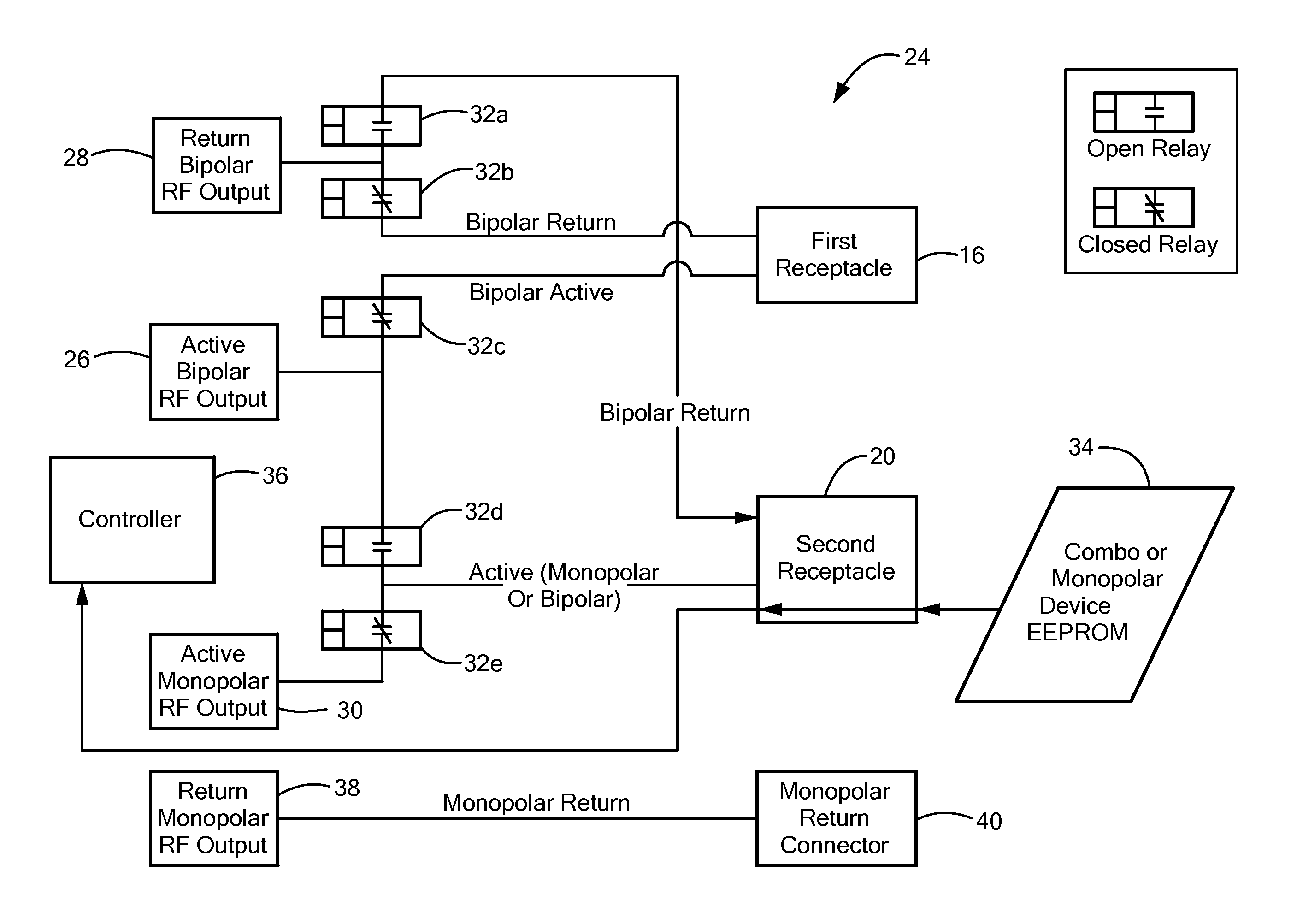
FIG. 2 is a circuit diagram of a switching circuit of a radiofrequency generator of the electrosurgical unit shown in FIG. 1.
DETAILED DESCRIPTION
As used here, relational terms, such as "first" and "second," "top" and "bottom," "front and rear," and the like, may be used solely to distinguish one entity or element from another entity or element without necessarily requiring or implying any physical or logical relationship or order between such entities or elements.
Referring now to the drawings in which like reference designators refer to like elements, there is shown in FIG. 1 and exemplary electrosurgical unit ("ESU") constructed in accordance with the principles of the present application and designated generally as "10." The ESU 10 may include a radiofrequency generator 12 configured to house and electrically couple the components and circuits of the ESU 10 and a touch actuated display 14 configured to receive energy requests from one or more electrosurgical hand pieces that electrically couple to the radiofrequency generator 12, display treatment progress and measurements, for example, impedance, and initiate and/or terminate the supply of radiofrequency energy and fluid with one or more electrosurgical hand pieces that may be electrically coupled to the ESU 10. In an exemplary configuration, the ESU 10 includes a first receptacle 16, which may be a 3-pin connector configured to receive and electrically couple with a first electrosurgical hand piece 18 configured to deliver bipolar radiofrequency energy to tissue. The ESU 10 may further include a second receptacle 20, for example, a 7-pin receptacle, configured to receive and electrically couple with a second electrosurgical hand piece 22 configured to deliver at least one of monopolar radiofrequency energy or a combination of bipolar radiofrequency energy and monopolar radiofrequency energy. In an exemplary configuration, the second electrosurgical hand piece 22 is an electrosurgical hand piece constructed in accordance with the principles of the electrosurgical hand piece disclosed in pending U.S. application Ser. No. 14/688,723 entitled TELESCOPING DEVICE WITH SALINE IRRIGATION LINE, the entirety of which is expressly incorporated herein by reference.
The first receptacle 16 and the second receptacle 20 may be electrically coupled to switching circuit 24 of the generator 12 configured to allow simultaneous operation of the electrosurgical hand pieces 18 and 22 in the first receptacle 16 and the second receptacle 20. The switching circuit 24 may include an active bipolar radiofrequency output 26, a return bipolar radiofrequency output 28, and an active radiofrequency monopolar output 30 all electrically couplable together and to the first receptacle 16 and the second receptacle 20 through a plurality of relays 32. In particular, the first receptacle 16 may be in electrical communication with a first relay 32a and a second relay 32b disposed between the return bipolar radiofrequency output 28 and the first receptacle 16. The return bipolar radiofrequency output 28 is further disposed between the first relay 32a and the second relay 32b. A third relay 32c may also be electrically coupled to the first receptacle 16, the third relay 32c being disposed between the first receptacle 16 and the active bipolar radiofrequency output 26. Accordingly, the second relay 32b may be disposed between the first relay 32a and the third relay 32c.
When the generator 12 is operating in a mode to deliver electrical energy to both the first receptacle 16 and the second receptacle 20 for simultaneous operation of the electrosurgical hand pieces 18 and 22, the first relay 32a is set in an open position, the second relay 32b is set in a closed position, and the third relay 32c is set in a closed position. In such a configuration, current transmitted from the active bipolar radiofrequency output 26 is relayed toward the first receptacle 16 and current transmitted from the return bipolar radiofrequency output 28 is also transmitted to the first receptacle 16. Bipolar radiofrequency energy alternates from being transmitted from the return bipolar radiofrequency output 28 and the active bipolar radiofrequency output 28 to avoid a DC bias during bipolar radiofrequency treatment of tissue which may harm the patient. During simultaneous operation of the electrosurgical hand pieces 18 and 20, the first relay 32a is open, which prevents bipolar radiofrequency current from being transmitted to the second receptacle 20.
The second receptacle 20 is configured to receive and electrically couple with the second electrosurgical hand piece 22. In one configuration, the second electrosurgical hand piece 22 is a combination electrosurgical hand piece configured to deliver both monopolar and bipolar radiofrequency energy and in another configuration the second electrosurgical hand piece 22 is an electrosurgical hand piece configured to deliver monopolar energy only. Accordingly, the second receptacle 20 is configured to receive multiple types of hand pieces. In an exemplary configuration, the second electrosurgical hand piece 22 includes an EEPROM 34 configured to communicate the type of hand piece is coupled to the generator 12. For example, the EEPROM 34 may determine that the second electrosurgical hand piece 22 is an electrosurgical hand piece configured to deliver both monopolar and bipolar radiofrequency energy. If bipolar energy is requested by the user, the relays 32 are set such that bipolar energy is delivered only to the second receptacle 20 and not to the first receptacle 16. If either a monopolar only electrosurgical hand piece 22 is electrically coupled to the second receptacle 20 or monopolar energy is selected from a combination second electrosurgical hand piece 22, a controller 36 in communication with the EEPROM 34 determines that monopolar energy is to be delivered to the second receptacle 20 and allows for simultaneous delivery of monopolar and bipolar energy.
Continuing to refer to FIG. 2, the second receptacle 20 is configured to be electrically couplable to the active bipolar radiofrequency output 26, the return bipolar radiofrequency output 28, and the active radiofrequency monopolar output 30. In particular, the active radiofrequency monopolar output 30 is configured to provide monopolar radiofrequency energy to the second receptacle 20 simultaneously with the active bipolar radiofrequency output 26 and/or the return bipolar radiofrequency output 28 providing bipolar energy to the first receptacle 16. To that end, a fourth relay 32d and a fifth relay 32e are electrically coupled to the second receptacle 20. In an exemplary configuration, the fourth relay 32d is disposed between the third relay 32c and the fifth relay 32e. Moreover, the fifth relay 32e is disposed between the active radiofrequency monopolar output 30 and the fourth relay 32d. In such a configuration, when the second receptacle 20 is configured to provide radiofrequency energy simultaneously with the first receptacle 16.
In an exemplary operation of the switching circuit 24 to provide for simultaneous radiofrequency energy delivery to the first electrosurgical hand piece 18 and the second electrosurgical hand piece 22, when the first electrosurgical hand piece 18 is electrically coupled to the first receptacle 16, the first relay 32a is set in an open configuration and the second relay 32b and the third relay 32c are set in a closed configuration. Such a configuration allows both the active bipolar radiofrequency output 26 and the return bipolar radiofrequency output 28 to transmit radiofrequency energy to the first receptacle 16 through the third relay 32c and the second relay 32b respectively, which transfer the bipolar radiofrequency to the first electrosurgical hand piece 18. When the second electrosurgical hand piece 22, whether a monopolar only hand piece or a combination of monopolar or bipolar hand piece is electrically coupled to the second receptacle 20, the EEPROM 34 determines which second electrosurgical hand piece 22 is coupled to the second receptacle 20, and determines if monopolar energy is selected to be delivered. If monopolar energy is selected by the user to be used in the second receptacle 20, the controller 36 sets the relays 32 for simultaneous radiofrequency energy delivery to the first electrosurgical hand piece 18 and the second electrosurgical hand piece 22. In particular, the fourth relay 32d is set to an open configuration and the first relay 32e is set to a closed position such that monopolar radiofrequency energy transmitted from the active monopolar radiofrequency output is relay to the second receptacle 20 through the fifth relay 32e. The monopolar radiofrequency energy may then be transmitted from the second electrosurgical hand piece 22 to the patient and returned to the generator from a return monopolar radiofrequency output 38, which may be a grounded back plate, and back into the generator 12 through a monopolar return connector 40.
It will be appreciated by persons skilled in the art that the present invention is not limited to what has been particularly shown and described herein above. In addition, unless mention was made above to the contrary, it should be noted that all of the accompanying drawings are not to scale. A variety of modifications and variations are possible in light of the above teachings without departing from the scope and spirit of the invention, which is limited only by the following claims.
* * * * *
D00000
D00001
D00002
XML
uspto.report is an independent third-party trademark research tool that is not affiliated, endorsed, or sponsored by the United States Patent and Trademark Office (USPTO) or any other governmental organization. The information provided by uspto.report is based on publicly available data at the time of writing and is intended for informational purposes only.
While we strive to provide accurate and up-to-date information, we do not guarantee the accuracy, completeness, reliability, or suitability of the information displayed on this site. The use of this site is at your own risk. Any reliance you place on such information is therefore strictly at your own risk.
All official trademark data, including owner information, should be verified by visiting the official USPTO website at www.uspto.gov. This site is not intended to replace professional legal advice and should not be used as a substitute for consulting with a legal professional who is knowledgeable about trademark law.