Lower end fixing body for improving flow path resistance of in-core detector
Kim , et al. Sep
U.S. patent number 10,403,406 [Application Number 15/515,130] was granted by the patent office on 2019-09-03 for lower end fixing body for improving flow path resistance of in-core detector. This patent grant is currently assigned to KEPCO NUCLEAR FUEL CO., LTD.. The grantee listed for this patent is KEPCO NUCLEAR FUEL CO., LTD.. Invention is credited to Joo Hong Chun, Kyong Bo Eom, Dong Geun Ha, Sang Youn Jeon, Ba Leum Kim, Jae Ik Kim, Jin Sun Kim, Seong Soo Kim, O Cheol Kwon, Hak In Lee, Joo Young Ryu, Su Pil Ryu.


| United States Patent | 10,403,406 |
| Kim , et al. | September 3, 2019 |
Lower end fixing body for improving flow path resistance of in-core detector
Abstract
The present invention relates to a lower end fitting for reducing flow resistance due to an in-core instrument in a nuclear fuel assembly, that is, a lower end fitting (100) having a plurality of flow holes for a nuclear fuel assembly, in which the flow holes (121) are formed under an assembly groove in which an instrumentation tube (131) for a nuclear fuel assembly is inserted, and at least two or more flow holes (121) are formed at a predetermined distance from the central axis (C) of the instrumentation tube (131).
| Inventors: | Kim; Jin Sun (Daejeon, KR), Kim; Jae Ik (Daejeon, KR), Jeon; Sang Youn (Daejeon, KR), Eom; Kyong Bo (Daejeon, KR), Ha; Dong Geun (Daejeon, KR), Kim; Seong Soo (Daejeon, KR), Ryu; Joo Young (Daejeon, KR), Kwon; O Cheol (Daejeon, KR), Ryu; Su Pil (Daejeon, KR), Lee; Hak In (Daejeon, KR), Chun; Joo Hong (Daejeon, KR), Kim; Ba Leum (Daejeon, KR) | ||||||||||
|---|---|---|---|---|---|---|---|---|---|---|---|
| Applicant: |
|
||||||||||
| Assignee: | KEPCO NUCLEAR FUEL CO., LTD.
(Daejeon, KR) |
||||||||||
| Family ID: | 56107632 | ||||||||||
| Appl. No.: | 15/515,130 | ||||||||||
| Filed: | October 22, 2015 | ||||||||||
| PCT Filed: | October 22, 2015 | ||||||||||
| PCT No.: | PCT/KR2015/011223 | ||||||||||
| 371(c)(1),(2),(4) Date: | March 28, 2017 | ||||||||||
| PCT Pub. No.: | WO2016/093487 | ||||||||||
| PCT Pub. Date: | June 16, 2016 |
Prior Publication Data
| Document Identifier | Publication Date | |
|---|---|---|
| US 20170243663 A1 | Aug 24, 2017 | |
Foreign Application Priority Data
| Dec 11, 2014 [KR] | 10-2014-0178533 | |||
| Current U.S. Class: | 1/1 |
| Current CPC Class: | G21C 17/10 (20130101); G21C 3/3305 (20130101); G21C 17/108 (20130101); G21C 3/322 (20130101); G21C 15/02 (20130101); Y02E 30/38 (20130101); Y02E 30/30 (20130101) |
| Current International Class: | G21C 3/322 (20060101); G21C 15/02 (20060101); G21C 3/33 (20060101); G21C 17/108 (20060101); G21C 17/10 (20060101) |
| Field of Search: | ;376/352,443,362,313,254 |
References Cited [Referenced By]
U.S. Patent Documents
| 5488634 | January 1996 | Johansson |
| 5867550 | February 1999 | Beuerlein |
| 2003/0016776 | January 2003 | Smith et al. |
| 2005/0157836 | July 2005 | Broach et al. |
| 06-027274 | Feb 1994 | JP | |||
| 10-1994-0002701 | Oct 2000 | KR | |||
| 10-2004-0040432 | May 2004 | KR | |||
| 10-2005-0072054 | Jul 2005 | KR | |||
| 10-2000-0061665 | Jul 2010 | KR | |||
| 10-2011-0103392 | Jul 2010 | KR | |||
| 10-0984018 | Sep 2010 | KR | |||
| 10-2014-0019923 | Feb 2014 | KR | |||
| WO 2010/077906 | Jul 2010 | WO | |||
Assistant Examiner: Wasil; Daniel
Attorney, Agent or Firm: Rabin & Berdo, P.C.
Claims
What is claimed is:
1. A nuclear fuel assembly lower end fitting comprising: a flow channel plate on which a plurality of fuel rods and instrumentation tube are disposed; an assembly groove formed in the flow channel plate, wherein the instrumentation tube is inserted into the assembly groove, wherein an outer surface of the instrumentation tube contacts with a side wall of the assembly groove, wherein the assembly groove includes a center vertical axis; a plurality of first flow holes formed in the flow channel plate around the assembly groove; and a plurality of second flow holes formed in the flow channel plate under the assembly groove, wherein the second flow holes communicate with the assembly groove, wherein all of the second flow holes are spaced the same distance from the vertical axis at regular interval with each other, and none of the second flow holes extend under the vertical axis, and all of the second flow holes are spaced inward from the side wall of the assembly groove, wherein a lower end of the instrumentation tube does not block the second flow holes even when the lower end of the instrumentation tube contacts a bottom of the assembly groove.
2. The nuclear fuel assembly lower end fitting of claim 1, wherein the second flow holes are arranged symmetrically around the vertical axis.
Description
TECHNICAL FIELD
The present invention relates to a lower end fitting for reducing flow resistance due to an in-core instrument in a nuclear fuel assembly.
BACKGROUND ART
An in-core instrument (ICI) is a device for measuring the output of a nuclear reactor by measuring the density and temperature of neutron flux in a core of the nuclear reactor.
In the related art, in-core instruments were inserted into a core through the bottom of a reactor vessel, but there was a problem that the substances in the core of a reactor may leak through the hole formed through the bottom of the reactor vessel.
In order to solve this problem, all in-core instruments have been disposed close to a core through a hole at the top of a reactor vessel instead of the way of inserting them through the bottom of a reactor vessel.
In-core instruments inserted through the closure head reach the inside the nuclear fuel assembly through instrumentation tubes and their ends block cooling holes in the lower end fitting for the nuclear fuel assembly, depending on the insertion positions, so the flow rate of cooling water that flows into the instrumentation tubes may not be sufficiently secured.
RELATED ART DOCUMENT
1. Korean Patent No. 10-0984018 (registered on Sep. 17, 2010)
2. Korean Patent Application Publication No. 10-2011-0103392 (published on Sep. 20, 2011)
3. Korean Patent Application Publication No. 10-2000-0061665 (published on Oct. 25, 2000)
DISCLOSURE
Technical Problem
In order to solve the problems in the related art, an object of the present invention is to provide a lower end fitting for reducing flow resistance due to an in-core instrument in a nuclear fuel assembly.
Technical Solution
In order to accomplish the above object, the present invention provides a lower end fitting for a nuclear fuel assembly of the present invention that has flow holes for cooling an in-core instrument for a nuclear fuel assembly, in which at least two or more flow holes are formed at a predetermined distance from the central axis of an instrumentation tube.
In the present invention, the flow holes may be arranged symmetrically around the central axis of the instrumentation tube.
Advantageous Effects
According to the lower end fitting of the present invention, a plurality of flow holes for supplying cooling water to an instrumentation tube is circumferentially symmetrically arranged at a predetermined distance from the central axis of an instrumentation tube, so even if an end of the instrumentation tube comes in contact with a flow channel plate, the flow holes are not blocked, so smooth flow of cooling water can be secured and it is possible to reduce vibration of an in-core instrument and prevent frictional damage to the in-core instrument.
DESCRIPTION OF DRAWINGS
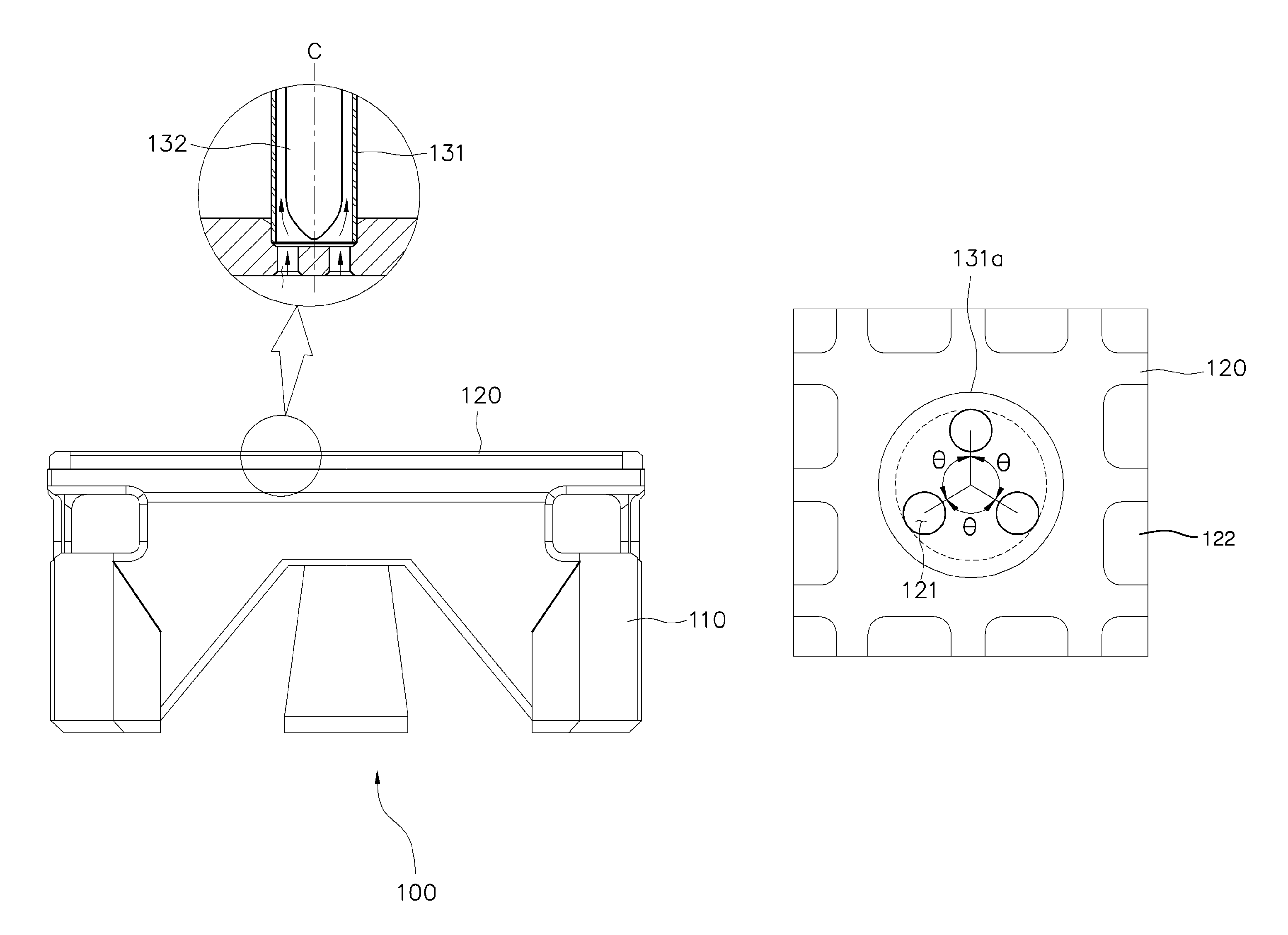
FIG. 1 is a view showing the configuration of a lower end fitting according to the present invention.
FIGS. 2A and 2B are views showing the structure of flow holes of a lower end fitting according to the present invention.
BEST MODE
Specific structures and functions stated in the following embodiments of the present invention are exemplified to illustrate embodiments according to the spirit of the present invention and the embodiments according to the spirit of the present invention can be achieved in various ways. Further, the present invention should not be construed as being limited to the following embodiments and should be construed as including all changes, equivalents, and replacements included in the spirit and scope of the present invention.
Further, in the specification, terms including "first" and/or "second" may be used to describe various components, but the components are not limited to the terms. The terms are used to distinguish one component from another component, and for instance, a first component may be referred to as a second component, and similarly, a second component may be referred to as a first component without being depart from the scope according to the spirit of the present invention.
It should be understood that when one element is referred to as being "connected to" or "coupled to" another element, it may be connected directly to or coupled directly to another element or be connected to or coupled to another element, having the other element intervening therebetween. On the other hand, it is to be understood that when one element is referred to as being "connected directly to" or "contact directly with" another element, it may be connected to or coupled to another element without the other element intervening therebetween. Expressions for describing relationships between components, that is, "between", "directly between", "adjacent to", and "directly adjacent to" should be construed in the same way.
Hereinafter, embodiments of the present invention will be described hereafter in detail with reference to the accompanying drawings.
Referring to FIGS. 1, 2A, and 2B, a lower end fitting 100 of a nuclear fuel assembly includes a flow channel plate 120 having a plurality of flow holes 122 on an enclosure 110 and is disposed under a plurality of fuel rods supported a plurality of support grids.
According to the present invention, at least two or more flow holes 121 are formed under an assembly groove 131a in which an instrumentation tube 131 is inserted in the flow channel plate 120, and said at least two or more flow holes 121 are formed at a predetermined distance from the central axis C of the instrumentation tube 131.
The flow holes 121 may be symmetrically arranged (at 360.degree./n, n is the number of the flow holes) around the central axis C of the instrumentation tube 131 and may be spaced at the same distance from the central axis C of the instrumentation tube 131.
For example, when three flow holes 121 are provided, they may be arranged with an angle of 120.degree. therebetween.
Reference numeral `131a` in FIGS. 2A and 2B indicates the assembly groove formed on which the flow channel plate 120 to insert an instrument tube.
According to the configuration of the lower end fitting of the present invention, since a plurality of holes is formed at a predetermined distance from the central axis C of the instrumentation tube 131 inside the assembly groove in which the instrumentation tube 131 is inserted, even if an end of an in-core instrument 132 comes in contact with the flow channel plate 120, the flow holes are not blocked, so smooth flow of cooling water can be secured.
Further, by the structure in which a plurality of flow holes is arranged symmetrically around the central axis of an instrumentation tube, cooling water can smoothly flow, so it is possible to reduce vibration of the in-core instrument and prevent frictional damage to the in-core instrument.
It will be apparent to those skilled in the art that the foregoing present invention is not limited by the foregoing embodiments and the accompanying drawings, and various modifications and changes may be made without departing from the scope and spirit of the invention.
TABLE-US-00001 <Description of the Reference Numerals in the Drawings> 100: Lower end fitting 110: Enclosure 120: Flow channel plate 121: Flow hole 131: Instrumentation tube 132: In-core instrument
* * * * *
D00000
D00001
D00002
XML
uspto.report is an independent third-party trademark research tool that is not affiliated, endorsed, or sponsored by the United States Patent and Trademark Office (USPTO) or any other governmental organization. The information provided by uspto.report is based on publicly available data at the time of writing and is intended for informational purposes only.
While we strive to provide accurate and up-to-date information, we do not guarantee the accuracy, completeness, reliability, or suitability of the information displayed on this site. The use of this site is at your own risk. Any reliance you place on such information is therefore strictly at your own risk.
All official trademark data, including owner information, should be verified by visiting the official USPTO website at www.uspto.gov. This site is not intended to replace professional legal advice and should not be used as a substitute for consulting with a legal professional who is knowledgeable about trademark law.