Display support apparatus
Bennett , et al. Sep
U.S. patent number 10,400,946 [Application Number 14/979,841] was granted by the patent office on 2019-09-03 for display support apparatus. This patent grant is currently assigned to Southco, Inc.. The grantee listed for this patent is Southco, Inc.. Invention is credited to Nicholas Paul Bennett, Stuart Kevan Buckland.


View All Diagrams
| United States Patent | 10,400,946 |
| Bennett , et al. | September 3, 2019 |
Display support apparatus
Abstract
The display supporting apparatus includes a base, a first arm, a second arm, and a display attachment bracket designed to be fixedly securable or attachable to a display. The display support apparatus further includes a mechanism for providing a constant orientation in relation to the base for the plane bisecting the range of rotation of the second arm about the pivot axis between the first arm and the second arm even as the first arm moves pivotally relative to the base.
| Inventors: | Bennett; Nicholas Paul (Redditch, GB), Buckland; Stuart Kevan (Malvern, GB) | ||||||||||
|---|---|---|---|---|---|---|---|---|---|---|---|
| Applicant: |
|
||||||||||
| Assignee: | Southco, Inc. (Concordville,
PA) |
||||||||||
| Family ID: | 45437837 | ||||||||||
| Appl. No.: | 14/979,841 | ||||||||||
| Filed: | December 28, 2015 |
Prior Publication Data
| Document Identifier | Publication Date | |
|---|---|---|
| US 20160109058 A1 | Apr 21, 2016 | |
Related U.S. Patent Documents
| Application Number | Filing Date | Patent Number | Issue Date | ||
|---|---|---|---|---|---|
| 13179457 | Jul 8, 2011 | 9277812 | |||
| 61362679 | Jul 8, 2010 | ||||
| 61362700 | Jul 9, 2010 | ||||
| 61363645 | Jul 12, 2010 | ||||
| Current U.S. Class: | 1/1 |
| Current CPC Class: | F16M 11/08 (20130101); F16M 11/12 (20130101); F16M 11/126 (20130101); F16M 11/2014 (20130101); F16M 13/02 (20130101); F16M 11/42 (20130101); F16M 11/24 (20130101); A47B 81/00 (20130101); F16M 11/10 (20130101); F16M 11/18 (20130101); F16M 11/02 (20130101); F16M 11/2092 (20130101); F16M 2200/044 (20130101); F16M 2200/028 (20130101); F16M 2200/041 (20130101); G09F 21/00 (20130101); G09F 7/18 (20130101); F16M 2200/068 (20130101); F16M 2200/063 (20130101) |
| Current International Class: | F16M 11/12 (20060101); F16M 13/02 (20060101); F16M 11/02 (20060101); F16M 11/42 (20060101); A47B 81/00 (20060101); F16M 11/08 (20060101); F16M 11/10 (20060101); F16M 11/18 (20060101); F16M 11/20 (20060101); F16M 11/24 (20060101); G09F 7/18 (20060101); G09F 21/00 (20060101) |
| Field of Search: | ;248/282.1 |
References Cited [Referenced By]
U.S. Patent Documents
| 1220578 | March 1917 | Wise |
| 1318703 | October 1919 | Stuchlak |
| 2033715 | March 1936 | Jacob |
| 2137004 | November 1938 | Langsner |
| 2256241 | September 1941 | De Lisle |
| 2332967 | October 1943 | Fatkin |
| 2424840 | July 1947 | Murphy |
| 3240925 | March 1966 | Paschke |
| 3279074 | October 1966 | McQuaid |
| 3401568 | September 1968 | Blatt |
| 3952984 | April 1976 | Dimitry |
| 3955241 | May 1976 | Little |
| 4082244 | April 1978 | Groff |
| 4236272 | December 1980 | Gronbach |
| 4356594 | November 1982 | Grosemans |
| 4402481 | September 1983 | Sasaki |
| 4403423 | September 1983 | Ford |
| 4548373 | October 1985 | Komura |
| 4562987 | January 1986 | Leeds |
| 4687167 | August 1987 | Skalka |
| 4695024 | September 1987 | Haven |
| 4783036 | November 1988 | Vossoughi |
| 4821159 | April 1989 | Pike |
| 4861107 | August 1989 | Vidwans |
| 4897015 | January 1990 | Abbe |
| 4928914 | May 1990 | Snodell |
| 5064340 | November 1991 | Genov |
| 5079799 | January 1992 | Rude |
| 5127617 | July 1992 | Bergetz |
| 5201896 | April 1993 | Kruszewski |
| 5231734 | August 1993 | Rude |
| 5246240 | September 1993 | Romich |
| 5251859 | October 1993 | Cyrell |
| 5257767 | November 1993 | McConnell |
| 5348260 | September 1994 | Acevedo |
| 5405117 | April 1995 | Davis |
| 5487524 | January 1996 | Bergetz |
| 5491874 | February 1996 | Lowry |
| 5564163 | October 1996 | Lowry |
| 5566048 | October 1996 | Esterberg |
| 5697125 | December 1997 | Gannon |
| 5697303 | December 1997 | Allan |
| 5738316 | April 1998 | Sweere |
| 5743503 | April 1998 | Voeller |
| 5752293 | May 1998 | Lowry |
| 5771539 | June 1998 | Wahlstedt |
| 5771540 | June 1998 | Carpenter |
| 5787549 | August 1998 | Soderlund |
| 5790910 | August 1998 | Haskin |
| 5799917 | September 1998 | Li |
| 5832987 | November 1998 | Lowry |
| 5842672 | December 1998 | Sweere |
| 5860335 | January 1999 | Lund |
| 5876008 | March 1999 | Sweere |
| 5878674 | March 1999 | Allan |
| 5918841 | July 1999 | Sweere |
| 5924665 | July 1999 | Sweere |
| 5934636 | August 1999 | Cyrell |
| 5947429 | September 1999 | Sweere |
| 5967479 | October 1999 | Sweere |
| 5975195 | November 1999 | Lowry |
| 5975472 | November 1999 | Hung |
| 5992809 | November 1999 | Sweere |
| 6012693 | January 2000 | Voeller |
| 6015120 | January 2000 | Sweere |
| 6019332 | February 2000 | Sweere |
| D423745 | April 2000 | Theis |
| 6095468 | August 2000 | Chirico et al. |
| 6102350 | August 2000 | Cyrell |
| 6141831 | November 2000 | Novin |
| 6182330 | February 2001 | Novin |
| 6189849 | February 2001 | Sweere |
| 6227508 | May 2001 | Panzarella |
| 6233791 | May 2001 | Theis |
| 6301748 | October 2001 | Su-Man |
| 6347433 | February 2002 | Novin |
| 6354549 | March 2002 | Sweere |
| 6367756 | April 2002 | Wang |
| 6394403 | May 2002 | Hung |
| 6409134 | June 2002 | Oddsen, Jr. |
| 6419196 | July 2002 | Sweere |
| 6467129 | October 2002 | Bae |
| 6478274 | November 2002 | Oddsen, Jr. |
| 6588062 | July 2003 | Novin |
| D478088 | August 2003 | Hamouz |
| 6609691 | August 2003 | Oddsen, Jr. |
| 6619606 | September 2003 | Oddsen, Jr. et al. |
| D488708 | April 2004 | Lam |
| D489599 | May 2004 | Lam |
| 6732988 | May 2004 | Ihalainen et al. |
| 6736364 | May 2004 | Oddsen, Jr. |
| 6775884 | August 2004 | Su-Man |
| 6791601 | September 2004 | Chang |
| D497537 | October 2004 | OKeene |
| 6871384 | March 2005 | Novin |
| 6883764 | April 2005 | Mileos |
| D505858 | June 2005 | OKeene |
| 6905101 | June 2005 | Dittmer |
| 6915994 | July 2005 | Oddsen, Jr. |
| 6915995 | July 2005 | Gillespie |
| 6973688 | December 2005 | Barker et al. |
| 6997422 | February 2006 | Sweere |
| 7014157 | March 2006 | Oddsen |
| 7028961 | April 2006 | Dittmer et al. |
| 7032870 | April 2006 | Sweere |
| 7048242 | May 2006 | Oddsen, Jr. |
| 7055215 | June 2006 | Ligtenberg |
| 7065834 | June 2006 | Lowry |
| 7079874 | July 2006 | Pontoppidan |
| 7099148 | August 2006 | Lee |
| D530595 | October 2006 | Lam |
| 7152836 | December 2006 | Pfister |
| D537323 | February 2007 | Saez |
| 7175152 | February 2007 | Dittmer |
| 7177144 | February 2007 | Ha et al. |
| 7178775 | February 2007 | Pfister |
| D537706 | March 2007 | LyHau |
| D538140 | March 2007 | LyHau |
| D538141 | March 2007 | Stenhouse |
| D538632 | March 2007 | LyHau |
| D538633 | March 2007 | LyHau |
| D539123 | March 2007 | LyHau |
| D539125 | March 2007 | LyHau |
| D539126 | March 2007 | Stenhouse |
| D539127 | March 2007 | LyHau |
| D539128 | March 2007 | LyHau |
| D539566 | April 2007 | Anderson |
| D539636 | April 2007 | Bremmon |
| D539637 | April 2007 | LyHau |
| D540154 | April 2007 | Bremmon |
| D540332 | April 2007 | Dittmer |
| 7207537 | April 2007 | Hung |
| D543210 | May 2007 | Stenhouse |
| D543547 | May 2007 | Muday |
| D543548 | May 2007 | Muday |
| 7243892 | July 2007 | Pfister |
| 7246780 | July 2007 | Oddsen, Jr. |
| 7252277 | August 2007 | Sweere et al. |
| 7303173 | December 2007 | Mileos |
| 7334765 | February 2008 | Hwang |
| 7338022 | March 2008 | Hung |
| 7345870 | March 2008 | Shin |
| 7364127 | April 2008 | Huang |
| 7380760 | June 2008 | Dittmer |
| 7387286 | June 2008 | Dittmer et al. |
| 7389965 | June 2008 | Oddsen, Jr. |
| 7395995 | July 2008 | Chen |
| 7395996 | July 2008 | Dittmer |
| 7398950 | July 2008 | Hung |
| 7458549 | December 2008 | Oddsen, Jr. |
| 7472458 | January 2009 | Oddsen, Jr. |
| 7487943 | February 2009 | Gillespie |
| 7497408 | March 2009 | Lim et al. |
| 7506853 | March 2009 | Sweere |
| 7513474 | April 2009 | Anderson et al. |
| 7530123 | May 2009 | Cao |
| 7540457 | June 2009 | Oddsen, Jr. et al. |
| 7546994 | June 2009 | Altonji et al. |
| 7567436 | July 2009 | Jeong |
| 7571883 | August 2009 | Van Groesen et al. |
| 7593218 | September 2009 | Hwang et al. |
| 7604210 | October 2009 | Oddsen, Jr. et al. |
| 7663699 | February 2010 | Sakata et al. |
| 7673839 | March 2010 | Zhang et al. |
| 7679892 | March 2010 | Jung |
| 7690605 | April 2010 | Lee |
| 7690611 | April 2010 | Asamarai |
| 7694927 | April 2010 | Chuang |
| 7717383 | May 2010 | Russell |
| 7748666 | July 2010 | Oddsen, Jr. et al. |
| 7766288 | August 2010 | Kim et al. |
| 7775485 | August 2010 | Asai et al. |
| 7793903 | September 2010 | Dittmer et al. |
| 7806378 | October 2010 | Oddsen, Jr. |
| 7810773 | October 2010 | Chi |
| 7815154 | October 2010 | Oh et al. |
| 7823849 | November 2010 | Dittmer et al. |
| 7832700 | November 2010 | Ciungan |
| 7841569 | November 2010 | Mileos |
| 7841570 | November 2010 | Mileos |
| D631445 | January 2011 | Dittmer |
| 7861998 | January 2011 | Huang |
| 7866622 | January 2011 | Dittmer |
| 7887014 | February 2011 | Lindblad |
| 7922137 | April 2011 | Derry et al. |
| 7954780 | June 2011 | Dittmer |
| 7975976 | July 2011 | Wohlford |
| 7992832 | August 2011 | Zhang et al. |
| D644648 | September 2011 | Anderson |
| 8056874 | November 2011 | Goodwin |
| 8070114 | December 2011 | Chen |
| 8070120 | December 2011 | Lange |
| 8074949 | December 2011 | Oddsen, Jr. |
| 8094438 | January 2012 | Dittmer et al. |
| D655297 | March 2012 | Magnusson |
| D660845 | May 2012 | Schmauch |
| 8191487 | June 2012 | Theesfeld |
| 8228668 | July 2012 | Asamarai |
| 8254092 | August 2012 | Russell et al. |
| 8256729 | September 2012 | Koch |
| 8310468 | November 2012 | Martin |
| 8328151 | December 2012 | Gwag |
| 8336840 | December 2012 | Song et al. |
| 8359982 | January 2013 | Lebel |
| 8366060 | February 2013 | Hung |
| 8469323 | June 2013 | Deros |
| 8490934 | July 2013 | Dittmer |
| 8508918 | August 2013 | Dittmer et al. |
| 8525939 | September 2013 | Perez Perez et al. |
| 8561955 | October 2013 | Stemple |
| 8693172 | April 2014 | Russell et al. |
| 8720838 | May 2014 | Bowman et al. |
| 8733722 | May 2014 | Hung |
| 8837127 | September 2014 | Dittmer et al. |
| 8870140 | October 2014 | Stemple |
| 8888062 | November 2014 | Novin |
| 8931748 | January 2015 | Bowman |
| 9022339 | May 2015 | Borg |
| 9062816 | June 2015 | Kulkarni et al. |
| 9103489 | August 2015 | Gwag |
| 9121543 | September 2015 | Dittmer et al. |
| 9228696 | January 2016 | Borloz et al. |
| 9243743 | January 2016 | Hunter et al. |
| 9266243 | February 2016 | Swartz et al. |
| 9279536 | March 2016 | Dittmer et al. |
| 9298254 | March 2016 | Ha et al. |
| 9355219 | May 2016 | Paydar |
| 9357846 | June 2016 | Hung |
| 9427364 | August 2016 | Grant |
| 2001/0023914 | September 2001 | Oddsen, Jr. |
| 2003/0132356 | July 2003 | Copeland |
| 2004/0084587 | May 2004 | Oddsen |
| 2004/0256526 | December 2004 | Burns |
| 2004/0262475 | December 2004 | Oddsen, Jr. |
| 2005/0284997 | December 2005 | Tisbo |
| 2006/0032998 | February 2006 | Depay |
| 2006/0065795 | March 2006 | Blackburn |
| 2006/0261228 | November 2006 | Hung |
| 2006/0266909 | November 2006 | Oddsen, Jr. et al. |
| 2006/0273231 | December 2006 | Huang |
| 2007/0001076 | January 2007 | Asamarai et al. |
| 2007/0023598 | February 2007 | Kim |
| 2007/0053151 | March 2007 | Capoferri |
| 2007/0080266 | April 2007 | Oddsen, Jr. |
| 2007/0114342 | May 2007 | Lee |
| 2007/0153459 | July 2007 | Wohlford et al. |
| 2007/0170321 | July 2007 | Smed |
| 2007/0187562 | August 2007 | Gaida |
| 2007/0222776 | September 2007 | Choi et al. |
| 2007/0252056 | November 2007 | Novin |
| 2007/0258200 | November 2007 | Choi et al. |
| 2007/0278361 | December 2007 | May |
| 2008/0001048 | January 2008 | Woo et al. |
| 2008/0001866 | January 2008 | Martin |
| 2008/0006748 | January 2008 | Watanabe et al. |
| 2008/0006751 | January 2008 | Chen |
| 2008/0016650 | January 2008 | Moon |
| 2008/0019393 | January 2008 | Yamaki |
| 2008/0029661 | February 2008 | Chen |
| 2008/0029670 | February 2008 | Hung |
| 2008/0078906 | April 2008 | Hung |
| 2008/0100996 | May 2008 | Wang |
| 2008/0105807 | May 2008 | Oh |
| 2008/0117578 | May 2008 | Moscovitch |
| 2008/0132786 | June 2008 | Asai |
| 2008/0135707 | June 2008 | Derry et al. |
| 2008/0164395 | July 2008 | Chang |
| 2008/0192418 | August 2008 | Zambelli |
| 2008/0234577 | September 2008 | Murkowski |
| 2008/0237439 | October 2008 | Oddsen |
| 2008/0283691 | November 2008 | Bliven |
| 2008/0296452 | December 2008 | Kim |
| 2008/0308699 | December 2008 | Kim et al. |
| 2009/0057514 | March 2009 | Oh |
| 2009/0072108 | March 2009 | Oleson |
| 2009/0078841 | March 2009 | Oddsen, Jr. et al. |
| 2009/0236484 | September 2009 | Koch |
| 2010/0006727 | January 2010 | Boomgaarden |
| 2010/0172072 | July 2010 | Monaco |
| 2010/0239073 | September 2010 | Eaves |
| 2010/0258694 | October 2010 | Steger |
| 2011/0006175 | January 2011 | Gwag |
| 2011/0019344 | January 2011 | Russell |
| 2011/0108698 | May 2011 | Chen |
| 2011/0147546 | June 2011 | Monsalve |
| 2011/0260017 | October 2011 | Monsalve et al. |
| 2011/0278424 | November 2011 | Theis |
| 2011/0315843 | December 2011 | Hung |
| 2012/0025037 | February 2012 | Chang |
| 2012/0182709 | July 2012 | Asai |
| 2013/0119219 | May 2013 | Mifsud |
| 2013/0314890 | November 2013 | Smith |
| 2014/0138506 | May 2014 | Dahl et al. |
| 2015/0245708 | September 2015 | Abernethy et al. |
| 2015/0250315 | September 2015 | Gross et al. |
| 2015/0308610 | October 2015 | Zhao et al. |
| 2016/0116109 | April 2016 | Borloz et al. |
| 101184951 | May 2008 | CN | |||
| 101427299 | May 2009 | CN | |||
| 4442642 | Jun 1996 | DE | |||
| 1586803 | Oct 2005 | EP | |||
| 63280292 | Nov 1988 | JP | |||
| 0468978 | Mar 1992 | JP | |||
| 10126068 | May 1998 | JP | |||
| 2000095034 | Apr 2000 | JP | |||
| 3071020 | Jun 2000 | JP | |||
| 2000179538 | Jun 2000 | JP | |||
| 2001020939 | Jan 2001 | JP | |||
| 2001142407 | May 2001 | JP | |||
| 2001218133 | Aug 2001 | JP | |||
| 2002300496 | Oct 2002 | JP | |||
| 2004019916 | Jan 2004 | JP | |||
| 2004363788 | Dec 2004 | JP | |||
| 2005264970 | Sep 2005 | JP | |||
| 2007520304 | Jul 2007 | JP | |||
| 2008014472 | Jan 2008 | JP | |||
| 2008142331 | Jun 2008 | JP | |||
| 2009543131 | Dec 2009 | JP | |||
| 2010078739 | Apr 2010 | JP | |||
| 1020050058738 | Jun 2005 | KR | |||
| 2005074806 | Aug 2005 | WO | |||
Other References
|
Japanese Office Action for Japanese Application No. 2016/077539, dated Apr. 25, 2017. cited by applicant . Chinese Office Action for Application No. 2016100925586, dated Jun. 1, 2017, 5 pages. cited by applicant . Chinese Second Office Action for Chinese Application No. 201610092558.6, dated Feb. 2, 2018, including English translation, 7 pages. cited by applicant . Notice of Reasons for Rejection for Japanese Application No. 2016-077539, dated Feb. 6, 2018 with translation, 8 pages. cited by applicant . Japanese Decision of Rejection for Japanese Application No. 2016-077539, dated Dec. 11, 2018, with translation, 2 pages. cited by applicant . Japanese Decision of Declining of Amendment for Japanese Application No. 2016-077539, dated Dec. 11, 2018, with translation, 5 pages. cited by applicant . Chinese Office Action for Application No. 201610092558.6, dated Sep. 5, 2018 with translation, 20 pages. cited by applicant . Japanese Notice of Reasons for Rejection for Japanese Application No. 2017-206164, dated Sep. 18, 2018--6 pages. cited by applicant . Chinese Office Action for Chinese Application No. 201610092558.6, dated Apr. 2, 2019, with translation, 18 pages. cited by applicant . Drawings of the AV Series Dynamic Mounting Arm made by Southco, Inc., Oct. 7, 2009. cited by applicant . First Chinese Office Action dated Jul. 14, 2015 in Chinese Application No. 201180033819.2 (with English translation). cited by applicant . Illustration of the Ergotron 200 Series Monitor Arm, obtained from the Ergotron website, Jun. 29, 2010. cited by applicant . Illustration of the HumanScale Monitor Arm (M4V), obtained from the HumanScale website, Jun. 29, 2010. cited by applicant . Illustrations of drafting tables with parallel mechanisms, Wikipedia, Jun. 29, 2010. cited by applicant . Illustrations of the GCX-VHM monitor support arm with 16 in./40.6cm extension for flat panel displays, obtained from the GCX website, Jun. 29, 2010. cited by applicant . Illustrations of the Hergo Wall Mount Secured Angle (15-000036-L12) monitor support arm, obtained from the Hergo website, Jun. 29, 2010. cited by applicant . International Preliminary Report on Patentability for International Application No. PCT/US2011/043458 dated Jan. 8, 2013. cited by applicant . International Search Report for International Application No. PCT/US2011/043458 dated Feb. 9, 2012. cited by applicant . IPF-2 Monitor Arm--Specification, Olympus, Sep. 2009. cited by applicant . Omnimount product brochure, part #63HDARM-UA, part # 54DARMUA, part # 63HDARM, part # 63HDARMUA, 3 pages, 2005 (obtained from www.omnimount.com on or prior to Mar. 13, 2006). cited by applicant . Peerless product brochure, models PLA 2 and PLA 2S, 2 pages, 2003 (obtained from www.peerlessindustries.coom on or prior to Mar. 13, 2006). cited by applicant . Sanus Systems product assembly instructions, Vision Mount VMAA Flat Panel Wall Mount, 8 pages, obtained from www.sanus.com on or prior to Mar. 13, 2006. cited by applicant . Sanus Systems product assembly instructions, Vision Mount VMDD 26 Flat Panel Wall Mount, 8 pages, obtained from www.sanus.com on or prior to Mar. 13, 2006. cited by applicant . Entire patent prosecution history of U.S. Appl. No. 13/179,457, filed Jul. 8, 2011, entitled Display Support With First and Second Arms and Mechanism for Maintaining Constant Orientation of the Plane Bisecting the Range of Rotation of the Second Arm Relative to a Support Base. cited by applicant. |
Primary Examiner: Smith; Nkeisha
Attorney, Agent or Firm: RatnerPrestia
Parent Case Text
CROSS REFERENCE TO RELATED APPLICATIONS
This application claims the benefit of priority of U.S. Non-provisional application Ser. No. 13/179,457 filed on Jul. 8, 2011, which claimed the priority of U.S. Provisional Application for Patent Ser. No. 61/362,679, filed on Jul. 8, 2010, U.S. Provisional application for Patent Ser. No. 61/362,700, filed on Jul. 9, 2010, and U.S. Provisional application for Patent Ser. No. 61/363,645, filed on Jul. 12, 2010, which are all incorporated by reference herein in their entirety.
Claims
The invention claimed is:
1. A display support apparatus for supporting a display at a user selected position relative to a support structure, the display support apparatus comprising: a base adapted for attachment to the support structure; a first arm having a range of rotation about a first pivot axis between the first arm and the base, the first pivot axis extending through a first end portion of the first arm; a second arm having a range of rotation about a second pivot axis between the first arm and the second arm, the second pivot axis being located at a proximal end portion of the second arm; and a recess and a detent, the recess being configured to receive the detent when the second arm is in a resting position relative to the first arm, wherein the recess is configured to limit movement of the second arm relative to the first arm about the second pivot axis when the second arm is in the resting position, and to permit movement of the second arm from the resting position, in which the detent is positioned within the recess, to an extended position in which the second arm is moved relative to the first arm about a transverse axis angled relative to the second pivot axis, wherein, in the extended position, the recess is separated from the detent.
2. The display support apparatus of claim 1, wherein the recess and the detent are configured to prevent the second arm from being moved pivotally in a plane from the resting position without the detent and the recess first being separated at least a predetermined distance relative to one another.
3. The display support apparatus of claim 1, wherein the detent extends outwardly relative to the first end portion of the first arm.
4. The display support apparatus of claim 1 further comprising a pivot joint attached to a distal end portion of the second arm.
5. The display support apparatus of claim 4, wherein the recess is defined by a surface associated with the pivot joint.
6. The display support apparatus of claim 5, wherein the pivot joint includes a tilt shaft extending through a tilt shaft housing and one or more lateral arms extending from the tilt shaft housing.
7. The display support apparatus of claim 6, wherein the pivot joint is a two-axis pivot joint that allows pivotal movement about a vertical pivot axis and a horizontal pivot axis relative to the distal end portion of the second arm.
8. The display support apparatus of claim 7, wherein the vertical pivot axis and the horizontal pivot axis are oriented relative to a display attachment bracket such that the vertical and horizontal pivot axes are both perpendicular to a direction vector that is normal to a surface of the display when the display is attached to the display attachment bracket.
9. The display support apparatus of claim 8, wherein the pivot joint further comprises two adaptors, each adaptor attached to a respective end of the tilt shaft such that the two adaptors and the tilt shaft rotate together as a unit.
10. The display support apparatus of claim 9 further comprising a display attachment bracket attached to the adaptors.
11. The display support apparatus of claim 9 further comprising a counterbalancing spring housed within the tilt shaft housing, the spring having one end keyed to the tilt shaft housing and another end keyed to one of the adaptors.
12. The display support apparatus of claim 11, wherein the counterbalancing spring is configured to provide a counterbalancing force for a weight of the display to reduce the force required to tilt the display about a longitudinal axis of the tilt shaft and to prevent unintended movement of the display due to gravity.
13. The display support apparatus of claim 8, wherein the pivot joint further comprises one or more friction elements provided in the tilt shaft housing in frictional engagement with the tilt shaft.
14. The display support apparatus of claim 13, wherein the one or more friction elements are fixed against rotation at one end.
15. The display support apparatus of claim 13, wherein the one or more friction elements are oriented such that the one or more friction elements provide greater friction torque when the display attachment bracket is tilted downwardly than when the display attachment bracket is tilted upwardly.
16. The display support apparatus of claim 7 further comprising a display attachment bracket attached to the pivot joint.
17. The display support apparatus of claim 16, wherein the recess and the detent are configured to prevent rotation of the display attachment bracket about the vertical pivot axis without the detent and the recess first being separated at least a predetermined distance with respect to one another.
18. The display support apparatus of claim 16, wherein the display attachment bracket includes at least one bumper to provide a softer stop between the pivot joint and the display attachment bracket during rotation of the display attachment bracket about the horizontal pivot axis.
19. The display support apparatus of claim 6, wherein the pivot joint is attached to the distal end portion of the second arm by a vertical pivot shaft that passes through the one or more lateral arms.
20. The display support apparatus of claim 19 further comprising one or more rotation limiting washers configured to provide bearing surfaces between the second arm and the pivot joint.
21. The display support apparatus of claim 20, wherein the one or more rotation limiting washers include pegs engaging arc-shaped grooves to act as a rotational stop during rotation about the vertical pivot shaft.
22. The display support apparatus of claim 1, wherein the second arm comprises a first longitudinal link pivotally attached to a first knuckle at the proximal end portion and a second knuckle at a distal end portion, a second longitudinal link pivotally attached to the first knuckle at the proximal end portion and the second knuckle at the distal end portion, and a gas strut positioned between the first and second longitudinal links, and the second arm is connected to the first arm via the first knuckle.
23. The display support apparatus of claim 22 further comprising an adjustment screw axially constrained in the first knuckle and coupled to the gas strut by an adjustment bridge, wherein rotation of the adjustment screw causes movement of the adjustment bridge along the adjustment screw and enables vertical thrust provided by the arm to be varied and accommodate objects of various weights attached to the distal end of the second arm.
24. The display support apparatus of claim 1 further comprising rotation stops that limit the range of rotation of the first arm relative to the base about the first pivot axis.
25. The display support apparatus of claim 1, wherein the recess is a notch.
26. The display support apparatus of claim 1, wherein the detent is a fin.
27. A display support apparatus for supporting a display at a user selected position relative to a support structure, the display support apparatus comprising: a base adapted for attachment to the support structure; an arm having a range of rotation about a pivot axis between the arm and the base, the pivot axis extending through an end portion of the arm; and a recess and a detent, the recess being configured to receive the detent when the arm is in a resting position relative to the base, wherein the recess is configured to limit movement of the arm relative to the base about the pivot axis when the arm is in the resting position in which the detent is positioned within the recess and to permit movement of the arm relative to the base about a transverse axis angled relative to the pivot axis when the arm is moved from the resting position to an extended position in which the detent is separated from the recess.
28. The display support apparatus of claim 27, wherein the recess is a notch.
29. The display support apparatus of claim 27, wherein the detent is a fin.
Description
BACKGROUND OF THE INVENTION
1. Field of the Invention
The present invention is directed to a display supporting apparatus for supporting a display, for example, a flat screen monitor or the like, in a desired position for easy viewing by a user.
2. Discussion of the Prior Art
Many display supporting apparatuses for supporting flat screen or flat panel displays in a user selected position are known in the prior art. However, most of the prior art display supporting apparatuses have a base that is designed to be secured to a wall or some other fixed or stationary structure. None of the prior art display supporting apparatuses are seen to offer the advantages of the present invention that will become apparent from the detailed description of the invention provided below and the appended drawings.
SUMMARY OF THE INVENTION
The present invention is directed to a display supporting apparatus for supporting displays including but not limited to displays such as flat screen computer monitors or the like in a user selected position. The display supporting apparatus includes a base, a first arm, a second arm, and a display attachment bracket designed to be fixedly securable or attachable to the display while preferably being detachable or removable from the display using appropriate fasteners. In use the display attachment bracket moves with the display as a unit. The base is designed for fixed attachment to some support structure. Preferably, the base is designed such that the fixed attachment of the base to the support structure can be undone or reversed in order to allow for the adjustment of the position of the base relative to the support structure or to allow the removal of the base from the support structure or both. The first end of the first arm is pivotally attached to the base by a first pivot mechanism to provide for the pivotal attachment of the first arm to the base. The first end of the second arm is pivotally attached to the second end of the first arm by a second pivot mechanism to provide for the pivotal attachment of the second arm to the first arm. The first pivot mechanism includes pivot stops that limit the range of the pivotal movement of the first arm relative to the base. The display support apparatus further includes a mechanism for providing a constant orientation in relation to the base for the plane bisecting the range of rotation of the second arm about the pivot axis between the first arm and the second arm even as the first arm moves pivotally relative to the base.
Preferably, the second arm is of a four link configuration that allows the up-and-down movement of the display attachment bracket without affecting the orientation of the display attachment bracket relative to the base. The second arm also includes a telescoping gas strut to counter balance the weight of the display so as to maintain the vertical position of the monitor as selected by the user. In addition, the gas strut dampens the up-and-down movement of the monitor to give the user better control when moving the display vertically. The second end of the second arm is attached to the display attachment bracket by a two-axis pivot joint that allows the pivotal movement of the display attachment bracket about a vertical pivot axis and a horizontal pivot axis relative to the second end of the second arm. The vertical pivot axis and the horizontal pivot axis are oriented relative to the display attachment bracket such that they are both perpendicular to a direction vector that is normal, i.e. perpendicular, to the surface of the display screen when the display is attached to the display attachment bracket. A notch is provided in the second end of the second arm that receives a fin provided on the first end of the first arm when the second arm is lowered to rest in superimposed fashion on top of the first arm. This feature prevents the second arm from being moved pivotally in a horizontal plain from rest relative to the first arm without the second arm first being slightly raised to a predetermined height above the first arm. This feature prevents accidental movement of the display when a mobile cart, to which the display support apparatus is attached, is maneuvered.
The display support apparatus of the present invention is particularly well suited for supporting a display on a mobile or movable support structure such as an equipment cart. Equipment carts are typically used to support medical equipment, such as ultrasound or endoscopy equipment, that require a display for use by the user or operator. The display support apparatus of the present invention is designed to securely hold the display in place when the cart is being moved so that the display does not accidentally impact other objects or persons, which lessens the risk of damage or injury. Also, the display support apparatus of the present invention, by limiting the range of rotation of the first arm and by providing a constant orientation for the plane bisecting the range of rotation of the second arm about the pivot axis between the first arm and the second arm, limits the distance outside the footprint of the cart to which the center of mass of the display can be moved to thereby significantly reduce the probability that the equipment cart will tip over due to the destabilizing torque arising from the weight of the display.
It is an object of the present invention to provide a display support apparatus that supports a display at a user selected location and position relative to a support structure.
It is an object of the present invention to provide a display support apparatus that securely holds the display in place when the support structure is being moved.
It is an object of the present invention to provide a display support apparatus that limits the distance outside the footprint of the support structure to which the center of mass of the display can be moved in order to significantly reduce the probability that the support structure will tip over.
It is an object of the present invention to provide a display support apparatus having a base, a first arm and a second arm, rotation stops that limit the range of rotation of the first arm relative to the base, and a mechanism for providing a constant orientation relative to the base for the plane bisecting the range of rotation of the second arm about the pivot axis between the first arm and the second arm.
It is an object of the present invention to provide a display support apparatus having a base, a first arm and a second arm, a display attachment bracket, and a mechanism for providing a constant orientation relative to the base for the display attachment bracket even as the display is raised or lowered vertically due to the rotation of the longitudinal axis of the second arm in a vertical plane.
These and other objects of the invention will become readily apparent from a study of the attached detailed description of the invention and drawing figures.
BRIEF DESCRIPTION OF THE DRAWINGS
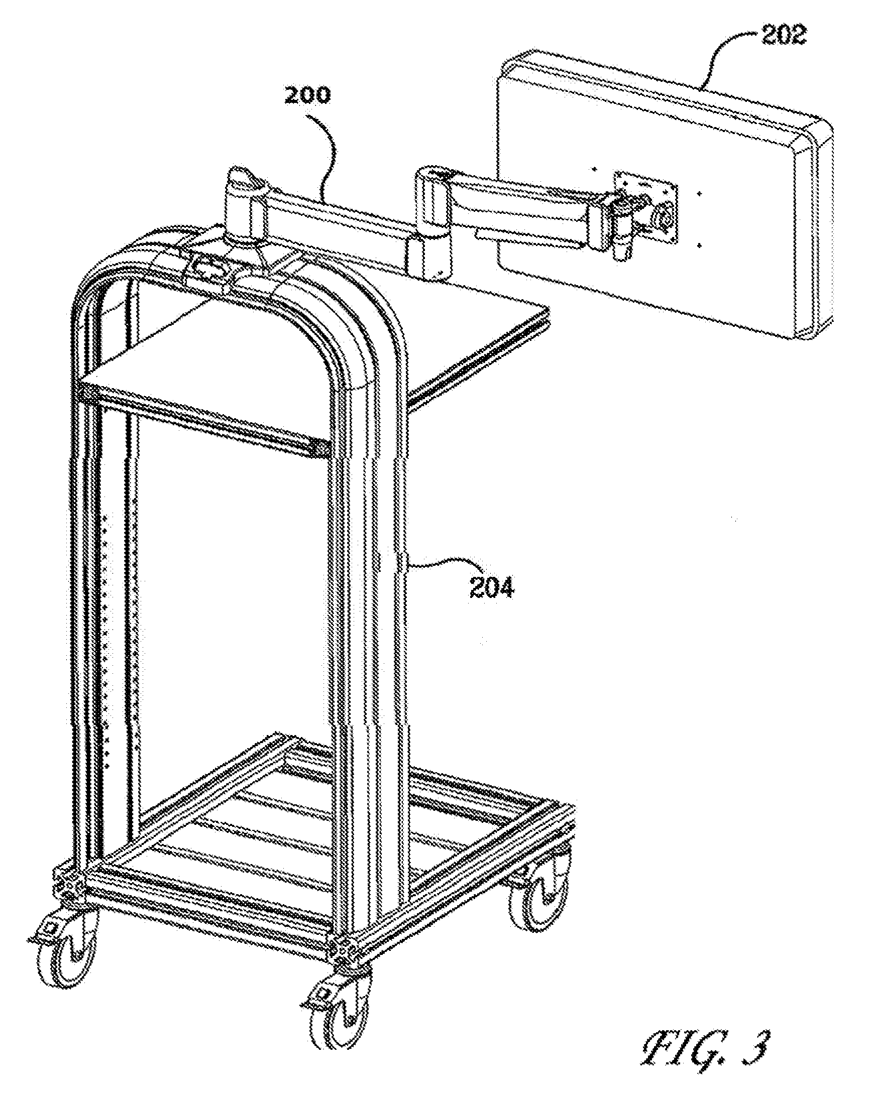
FIGS. 1-3 are environmental views of a display supporting apparatus according to the present invention.
FIG. 4 is an overall exploded view of the display supporting apparatus according to the present invention.
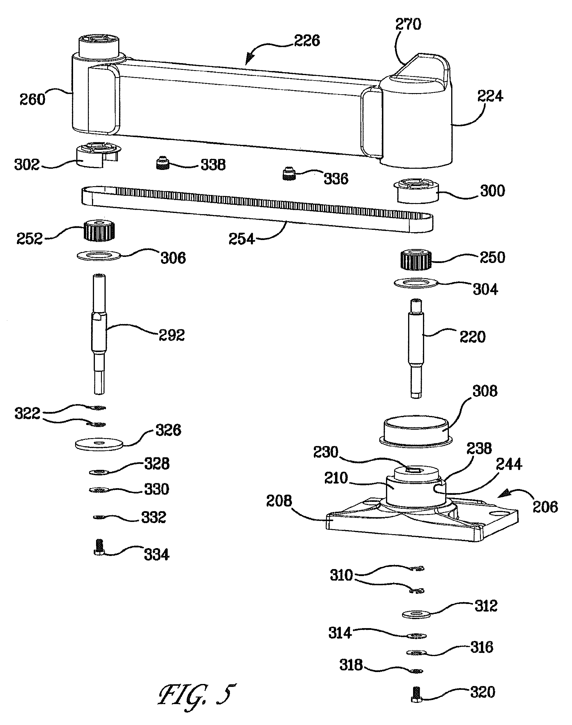
FIG. 5 is an exploded view of the first arm of the display supporting apparatus according to the present invention.
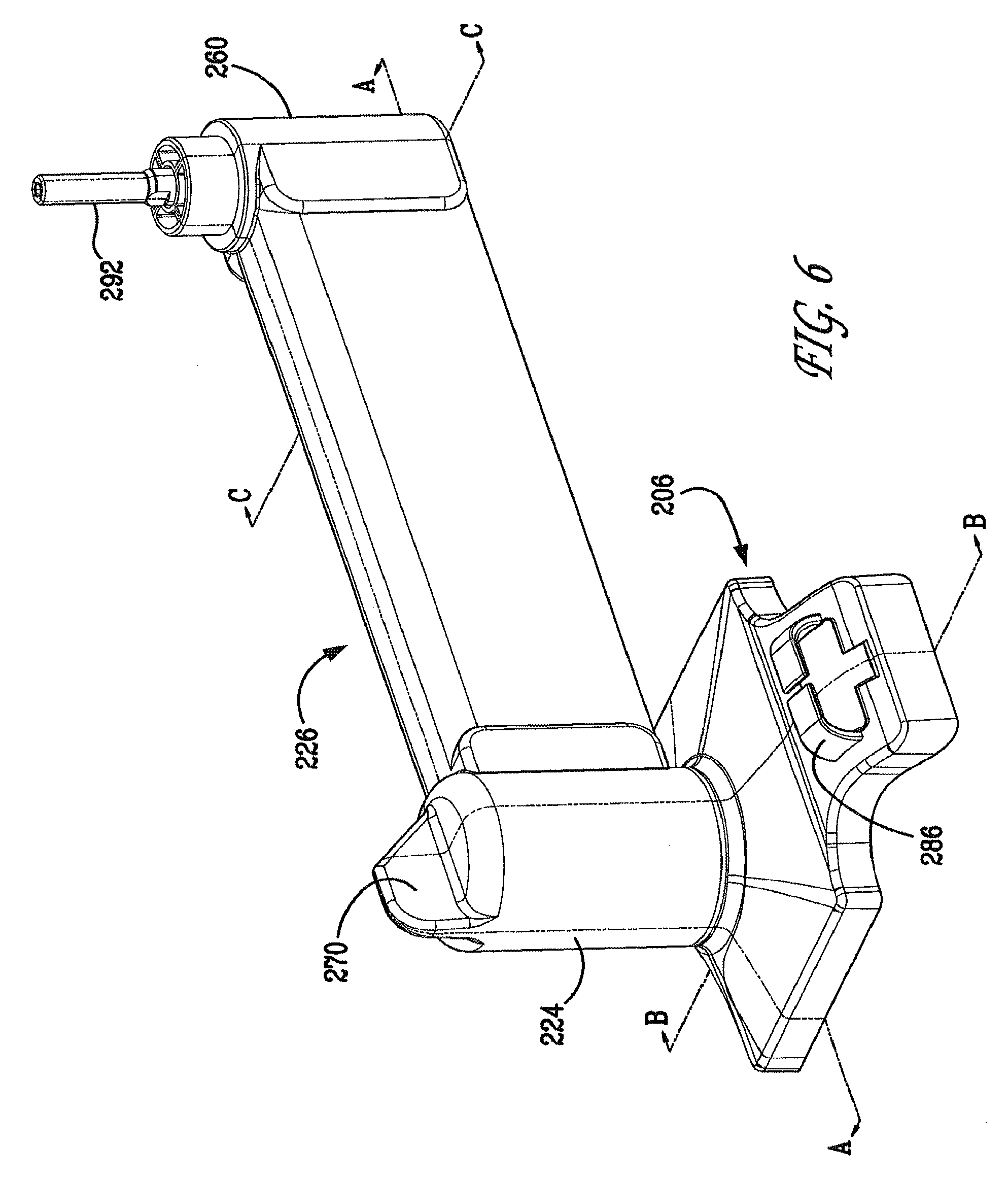
FIG. 6 is a perspective view of the first arm of the display supporting apparatus according to the present invention.
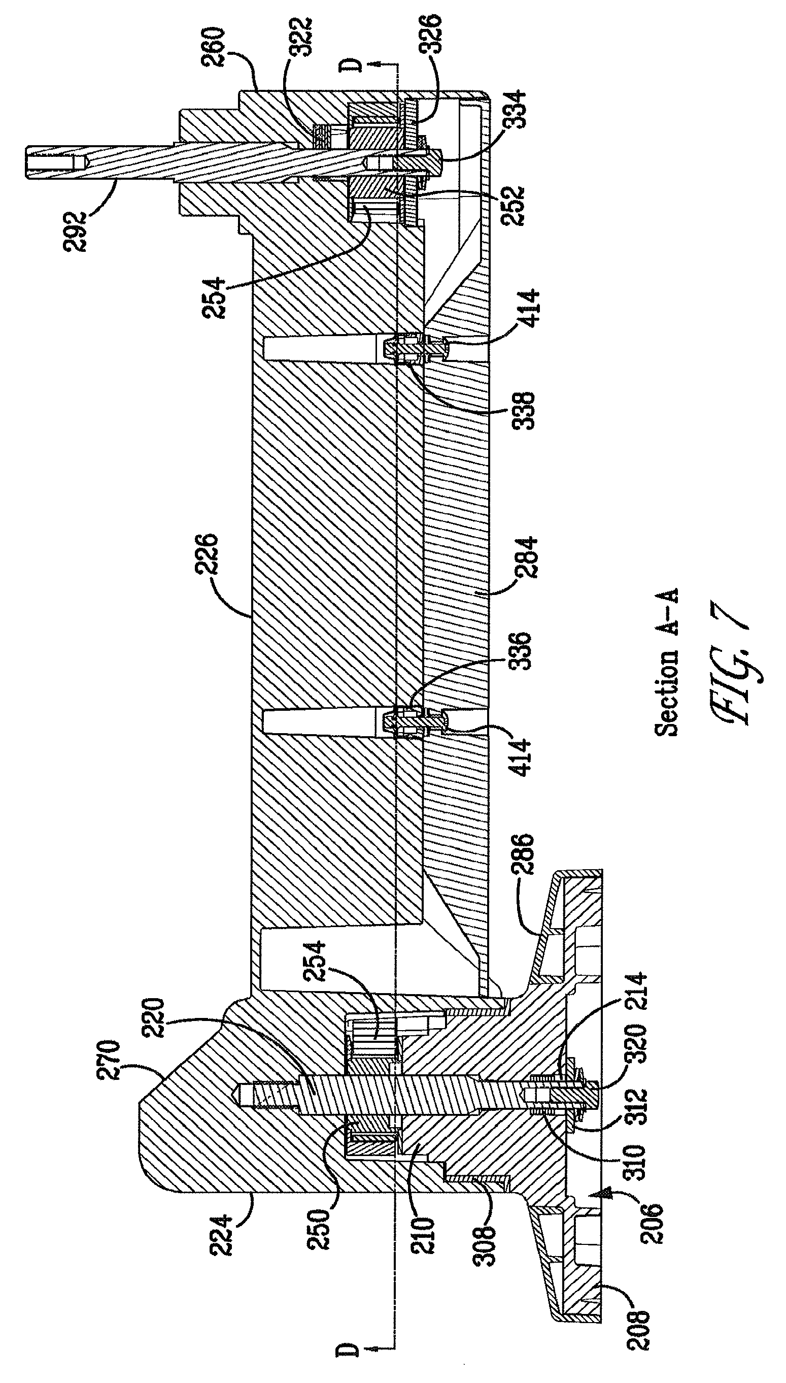
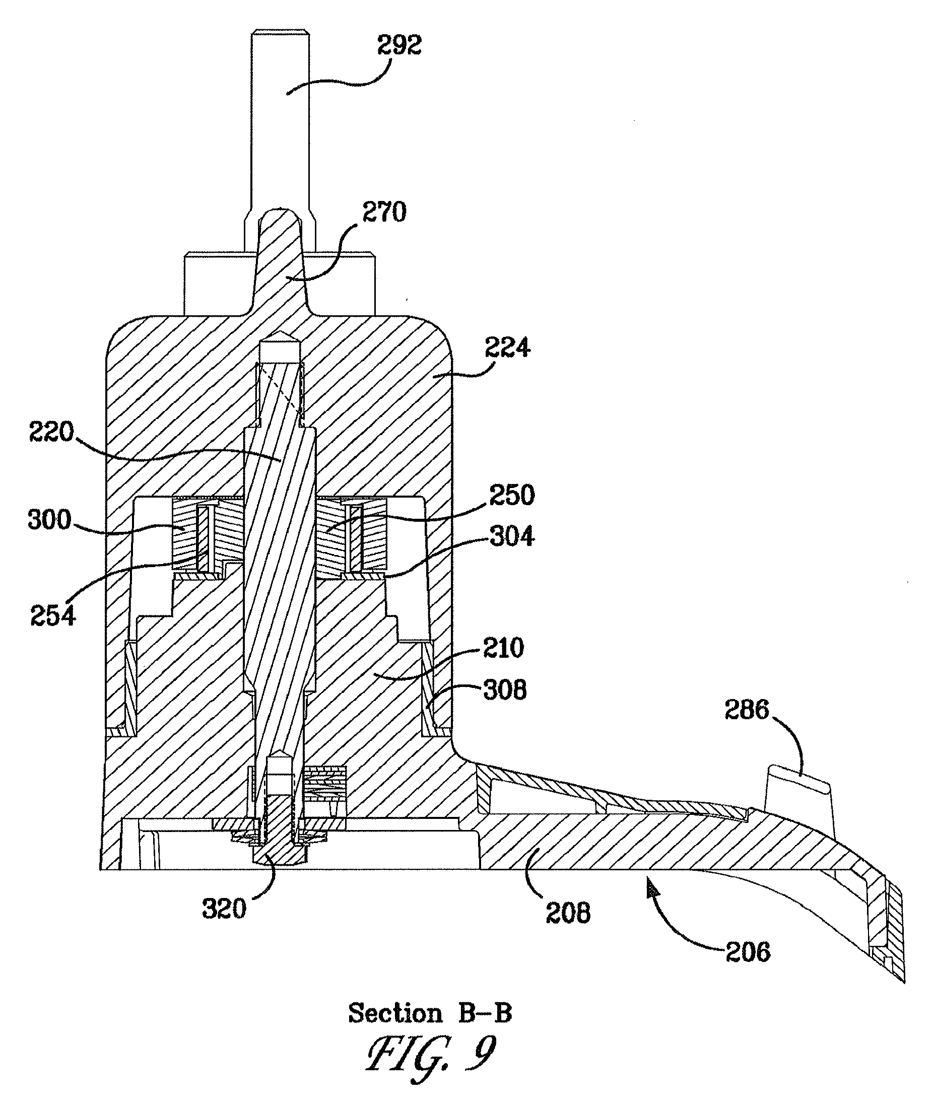
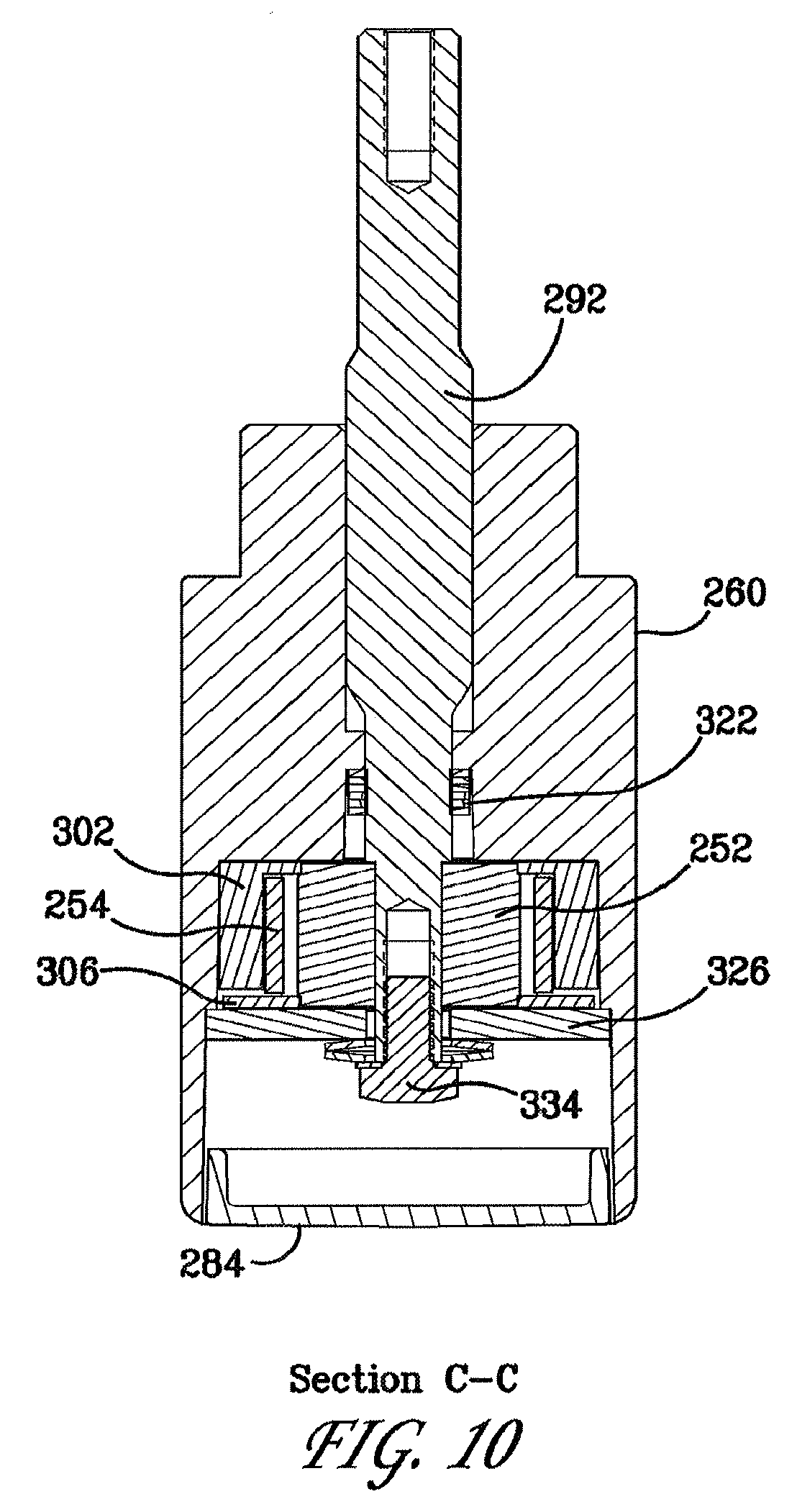
FIGS. 7-10 are cross sectional views of the first arm of the display supporting apparatus according to the present invention.
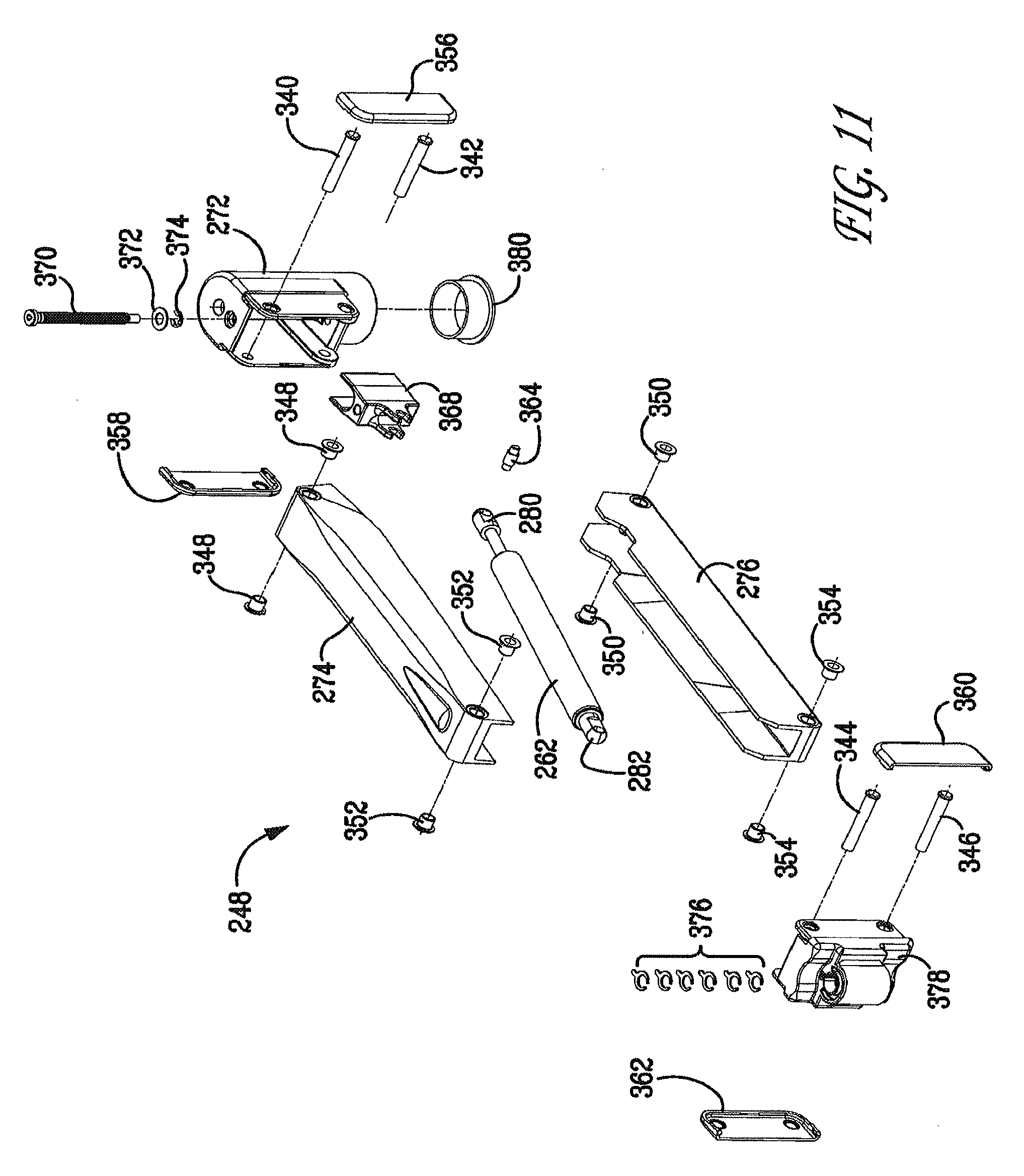
FIG. 11 is an exploded view of the second arm of the display supporting apparatus according to the present invention.
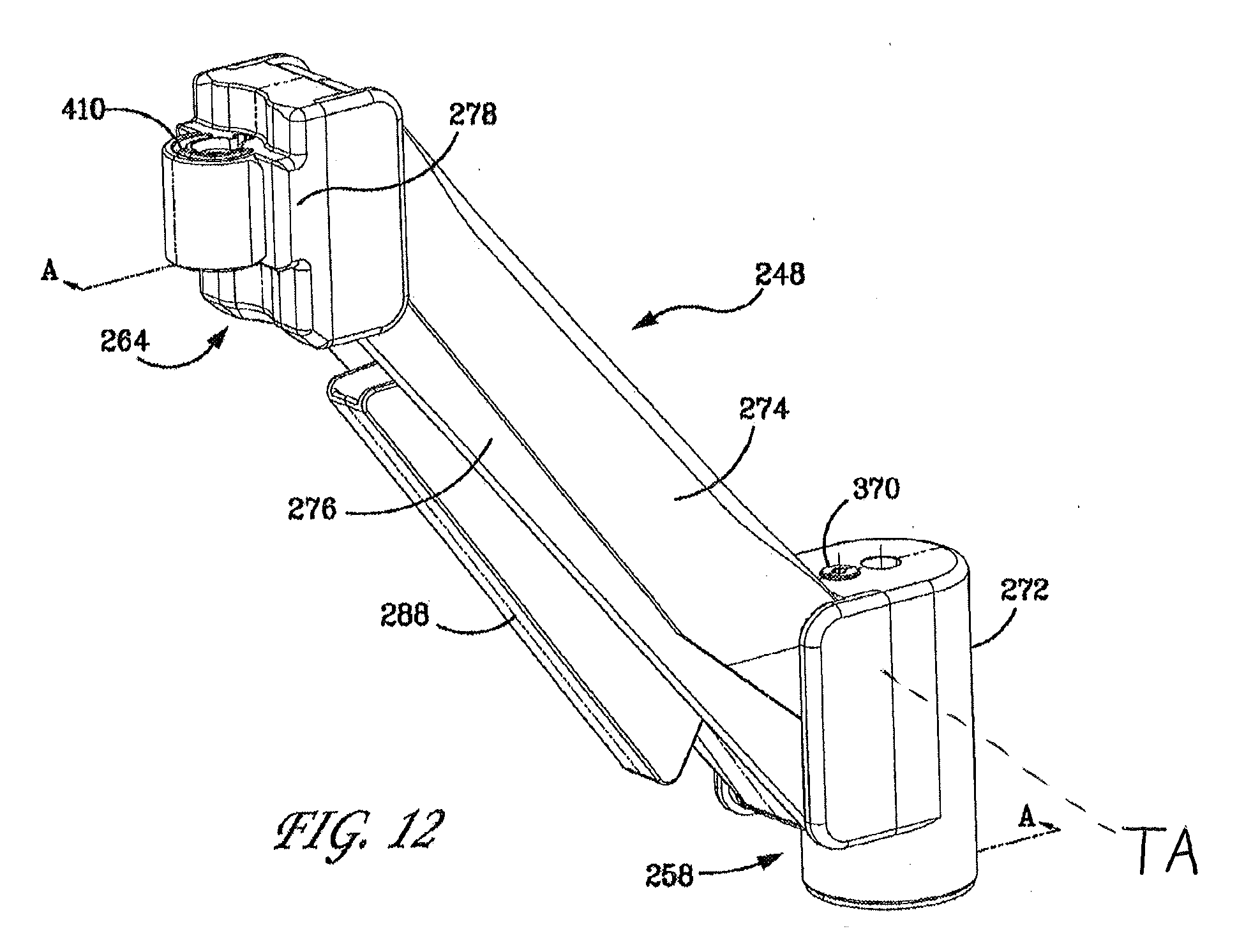
FIG. 12 is a perspective view of the second arm of the display supporting apparatus according to the present invention.
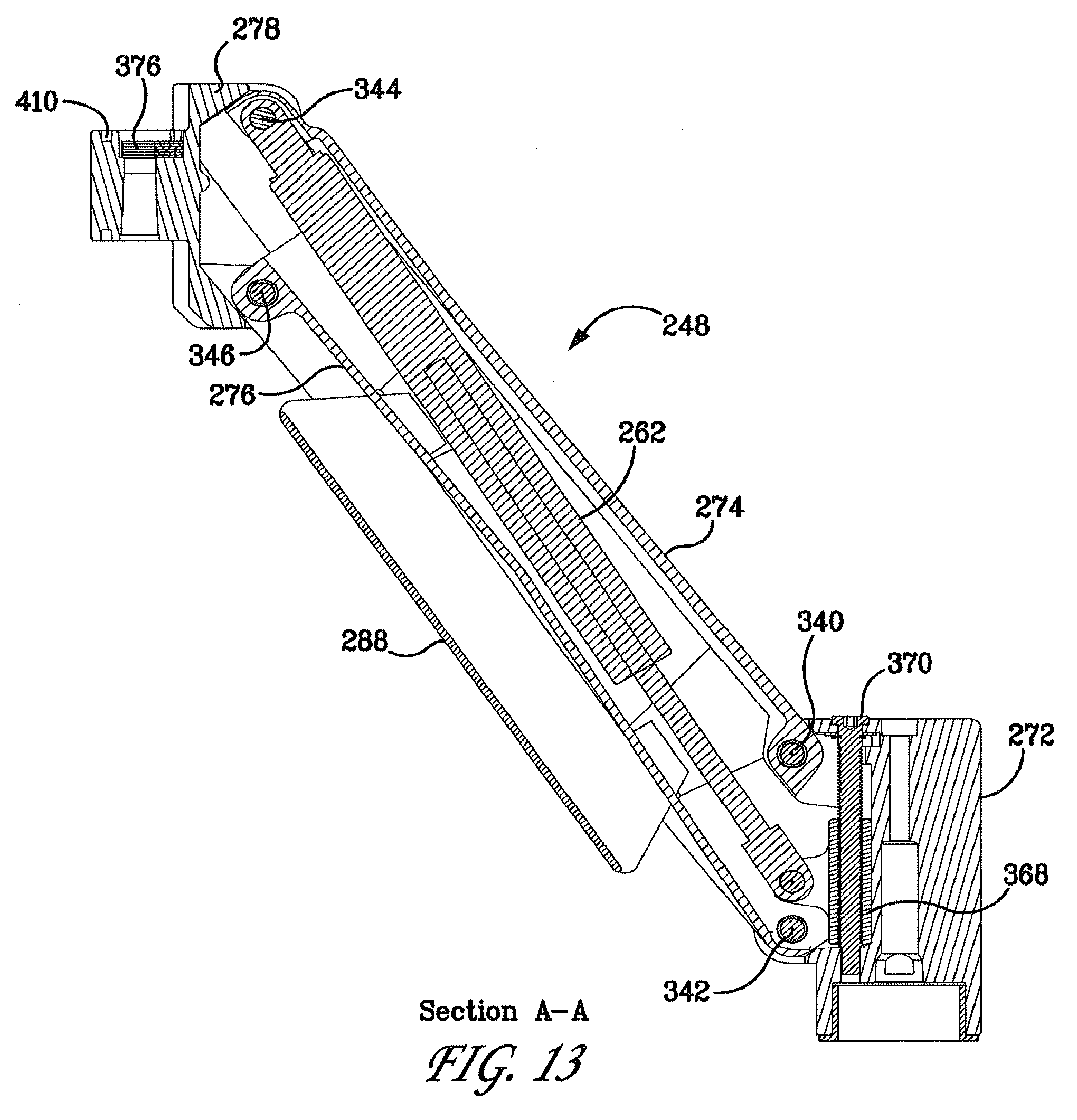
FIG. 13 is a cross sectional view of the second arm of the display supporting apparatus according to the present invention.
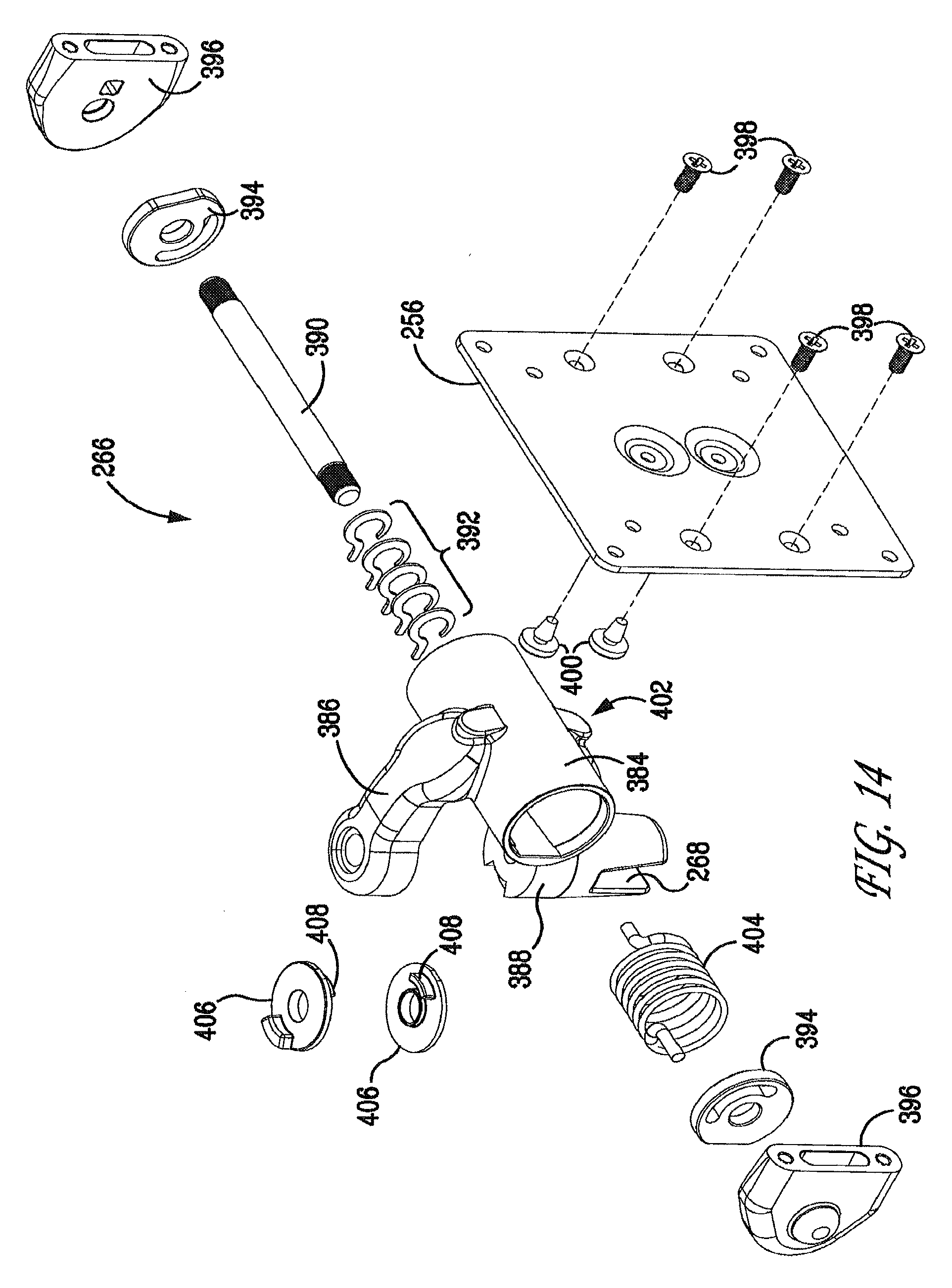
FIG. 14 is an exploded view of the two-axis pivot joint of the display supporting apparatus according to the present invention.
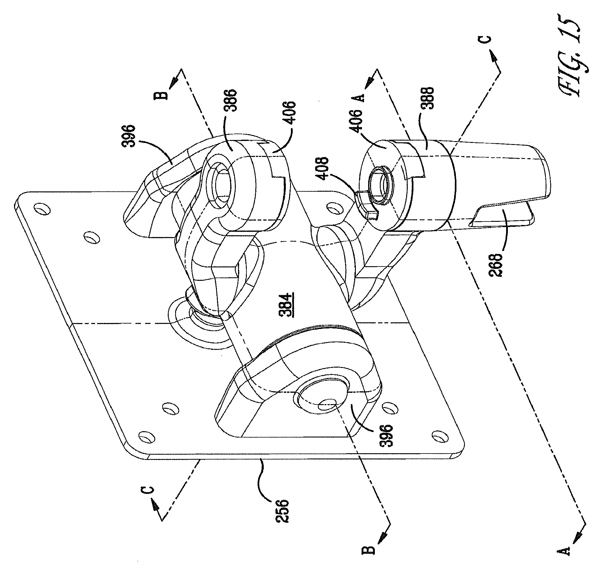
FIG. 15 is a perspective view of the two-axis pivot joint of the display supporting apparatus according to the present invention.
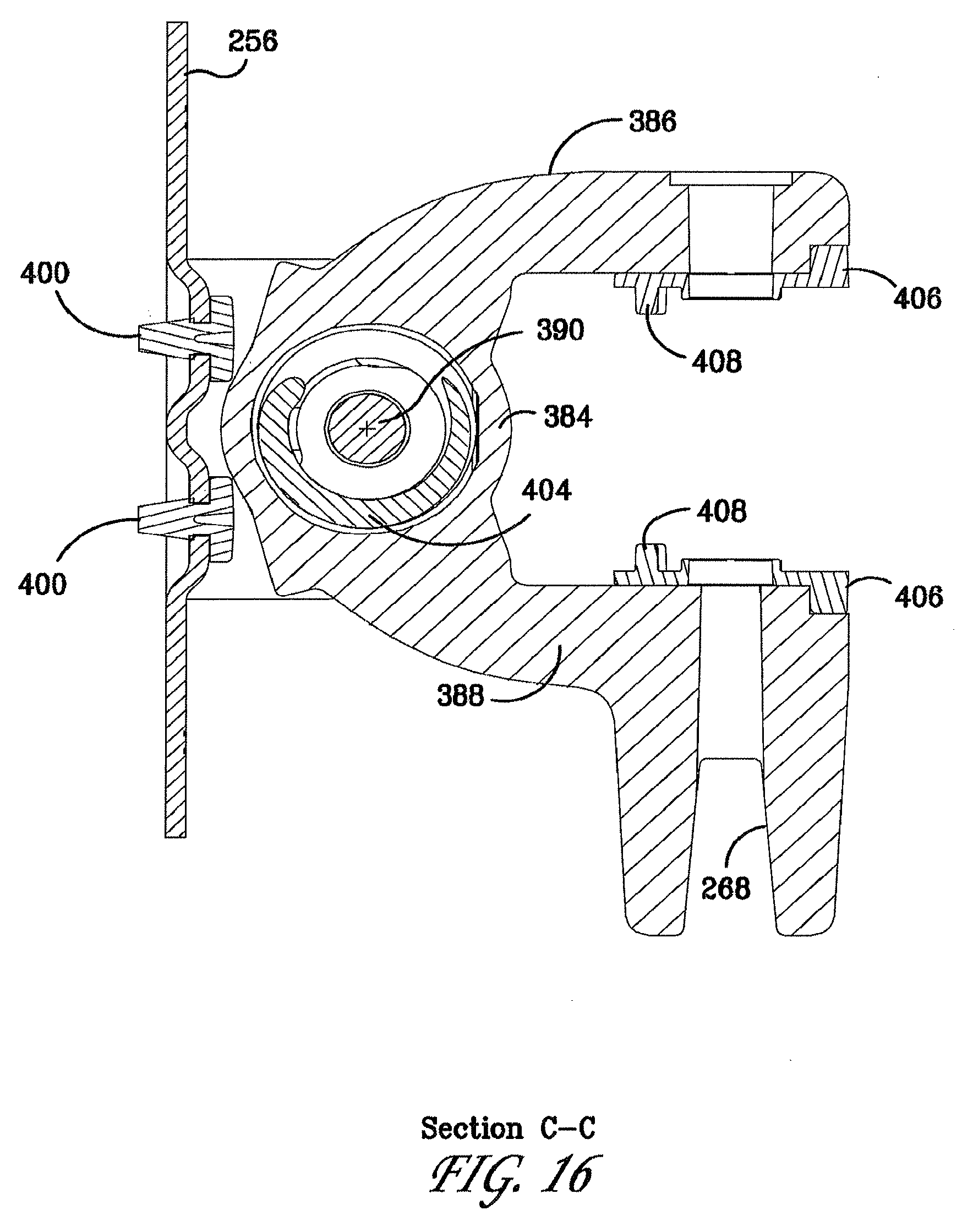
FIGS. 16-18 are cross sectional views of the two-axis pivot joint of the display supporting apparatus according to the present invention.
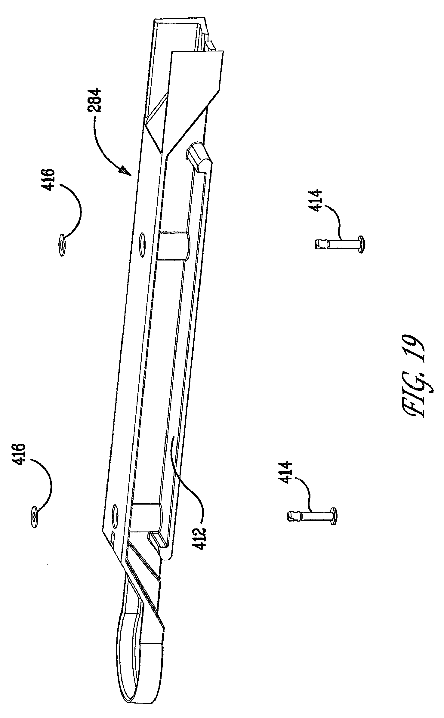
FIG. 19 is an exploded view of the cable tray assembly of the first arm of the display supporting apparatus according to the present invention.
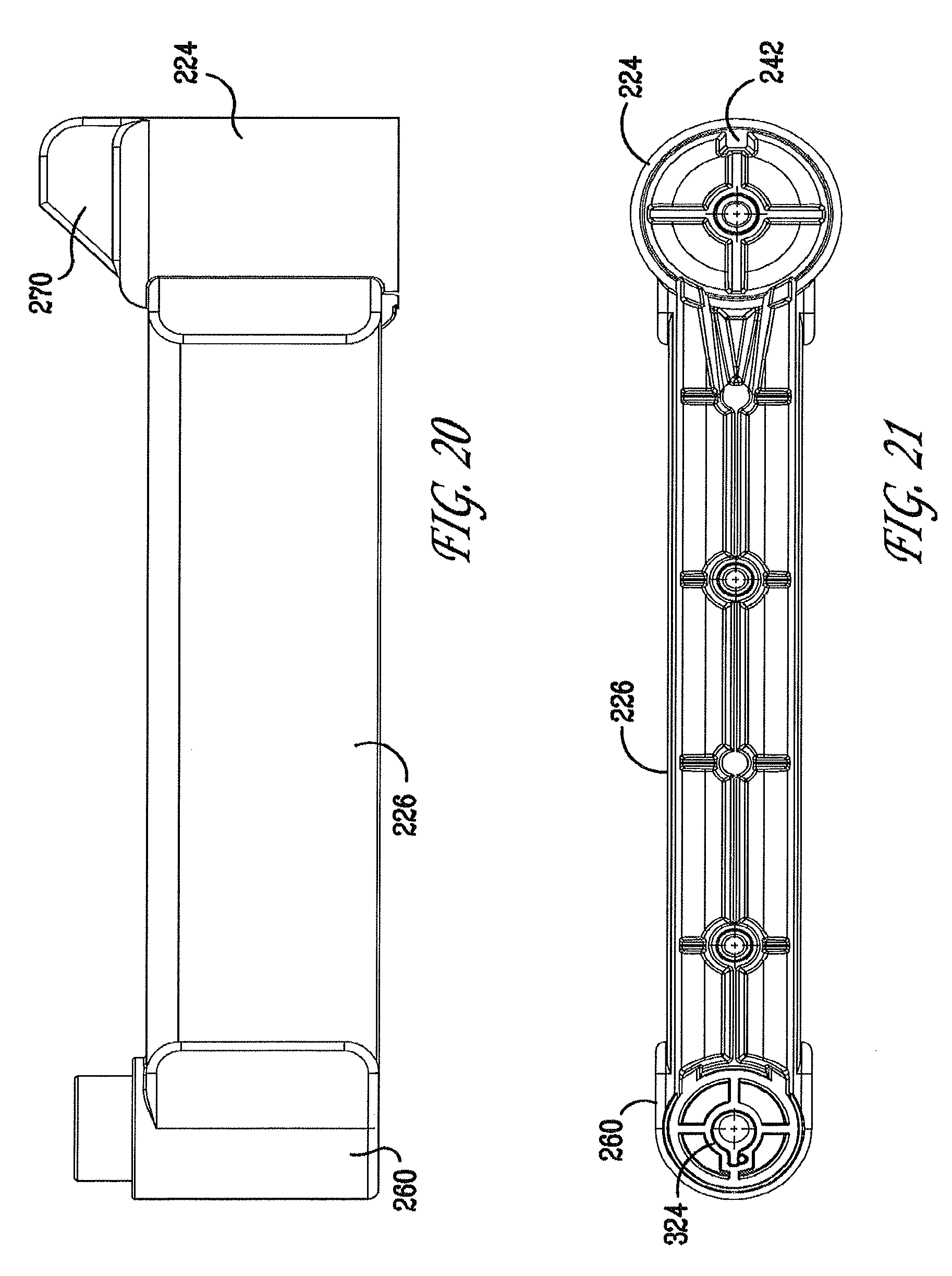
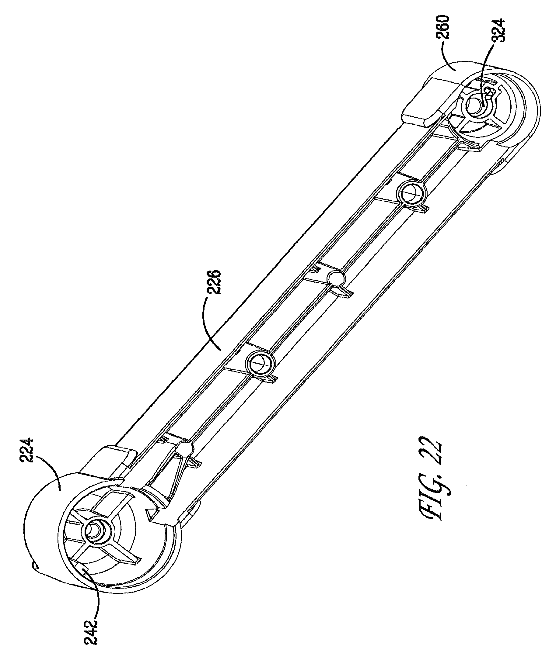
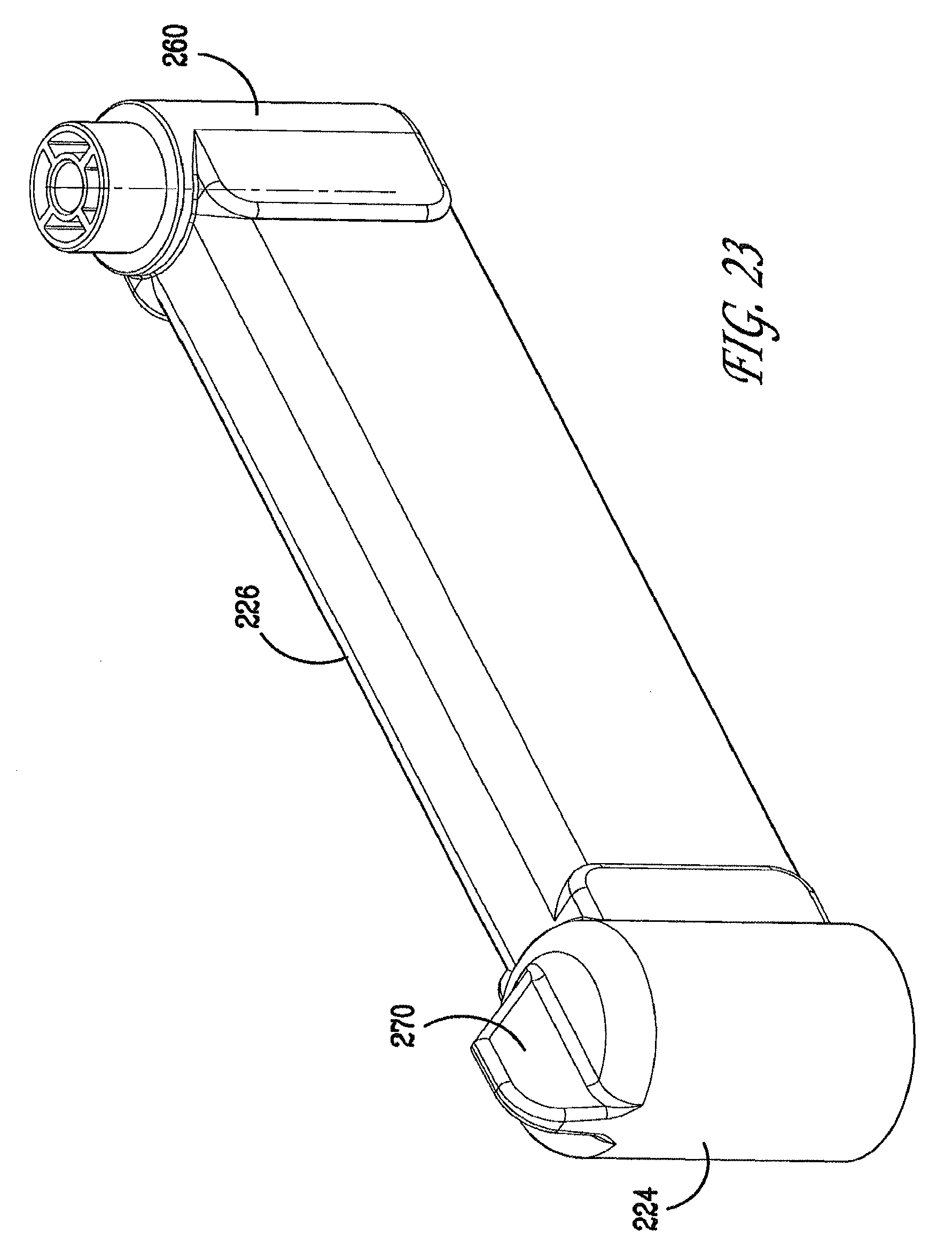
FIGS. 20-23 are views of the first arm of the display supporting apparatus according to the present invention.
FIGS. 24-25 are views of the base of the display supporting apparatus according to the present invention.
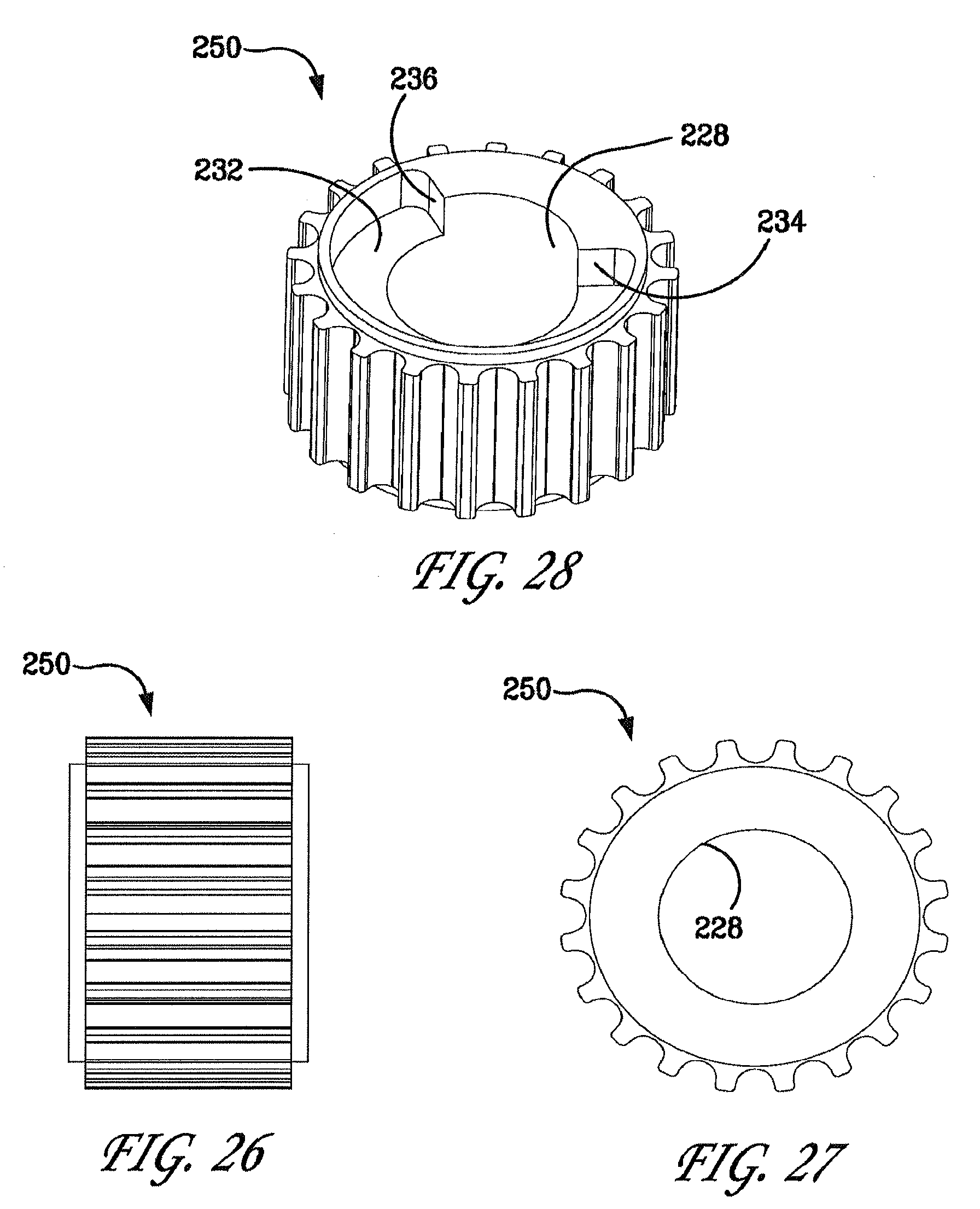
FIGS. 26-28 are views of the first pulley of the display supporting apparatus according to the present invention.
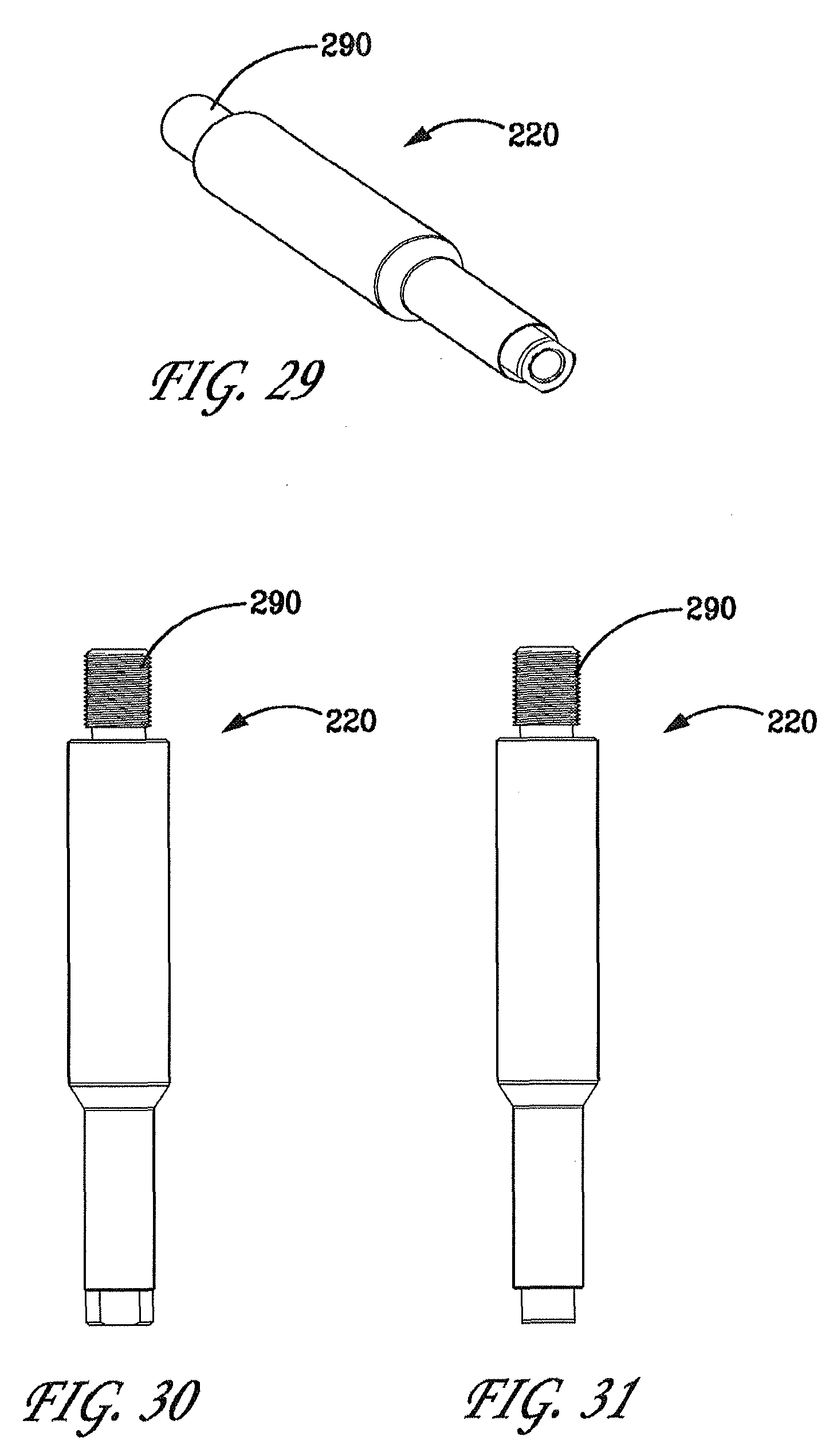
FIGS. 29-31 are views of the first pivot shaft of the display supporting apparatus according to the present invention.
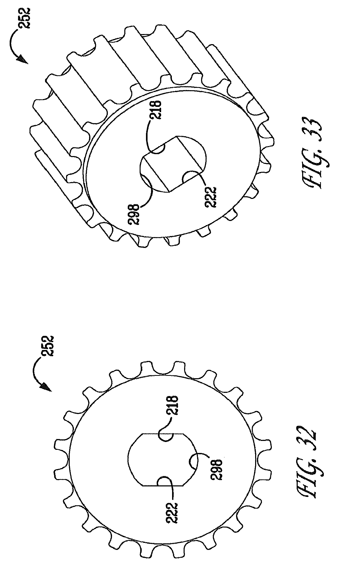
FIGS. 32-33 are views of the second pulley of the display supporting apparatus according to the present invention.
FIGS. 34-36 are views of the second pivot shaft of the display supporting apparatus according to the present invention.
FIG. 37 is a perspective view of a symmetrical friction element of the display supporting apparatus according to the present invention.
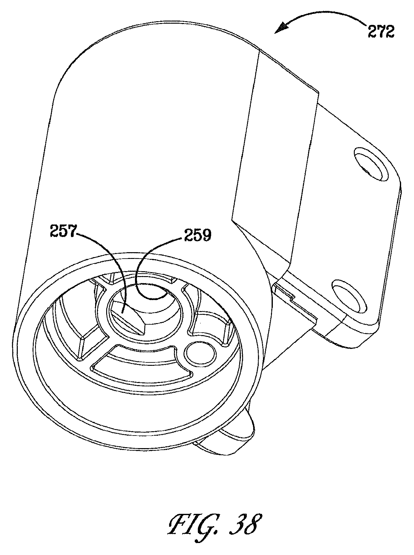
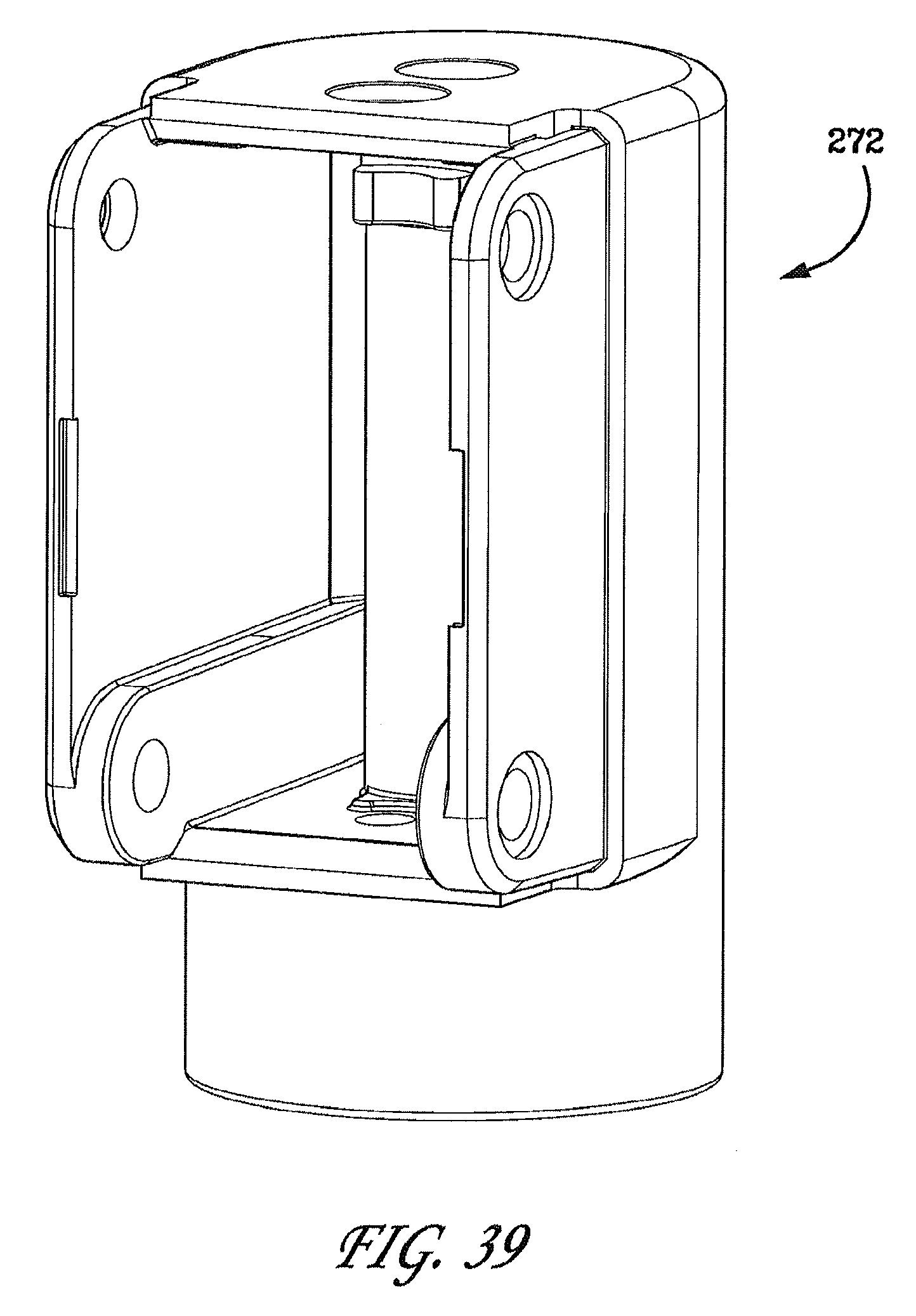
FIGS. 38-39 are views of the first knuckle of the display supporting apparatus according to the present invention.
FIG. 40 is a perspective view of the adjustment bridge of the display supporting apparatus according to the present invention.
FIGS. 41-42 are views of the adjustment screw of the display supporting apparatus according to the present invention.
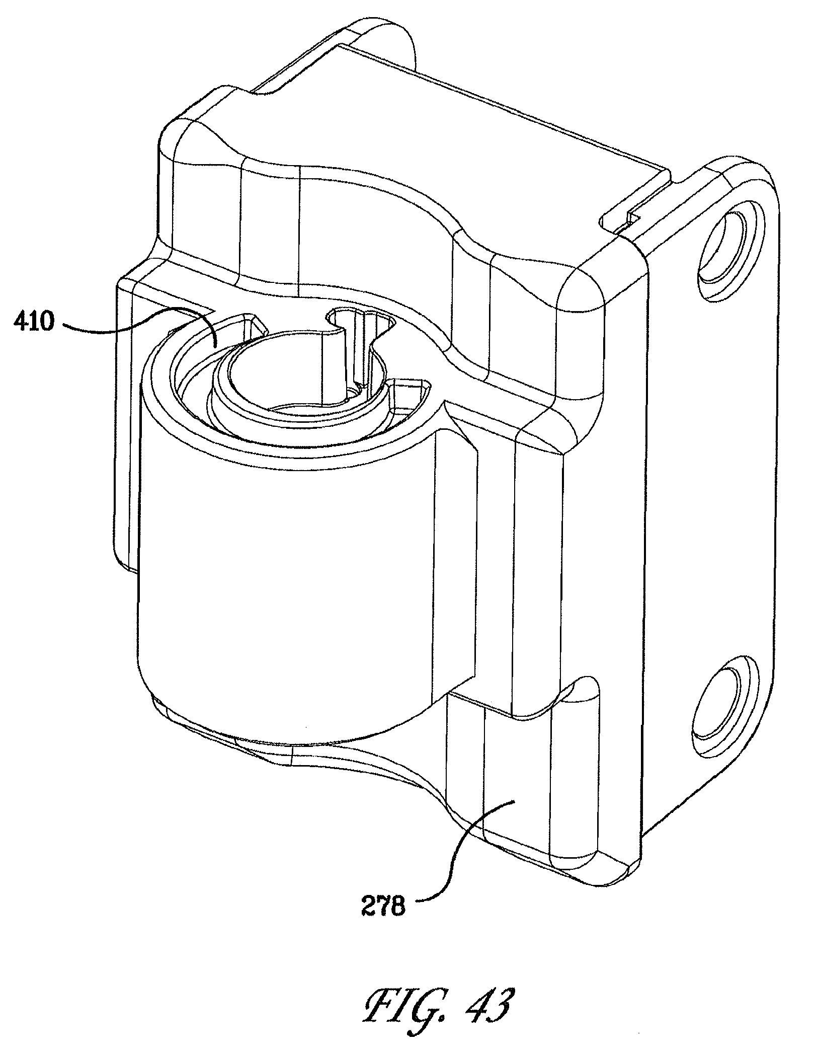
FIG. 43 is a perspective view of the second knuckle of the display supporting apparatus according to the present invention.
FIGS. 44-46 are views of the housing of the two-axis pivot joint of the display supporting apparatus according to the present invention.
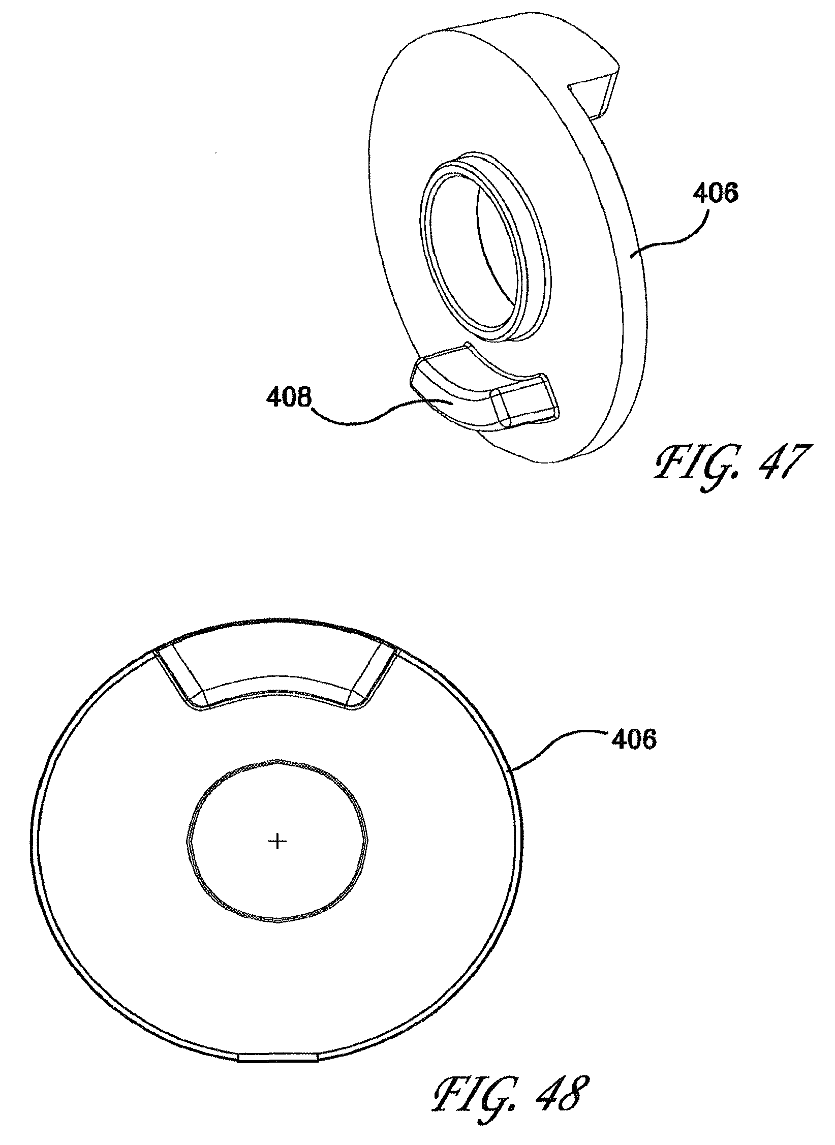
FIGS. 47-48 are views of one of two rotation limiting washers of the display supporting apparatus according to the present invention.
The same reference numerals are used consistently throughout the attached drawings. Where different reference numerals are used to refer to different parts that are structurally identical and a single set of close-up views illustrates the details of the structurally identical parts, reference numerals separated by a comma are used in the drawings to indicate that the illustration represents two different but structurally identical parts that have the same visual depiction.
DETAILED DESCRIPTION OF THE PREFERRED EMBODIMENTS
Referring to FIGS. 1-48, the preset invention is directed to a display supporting apparatus 200 for supporting a display 202 at a user selected location or position within its operational range relative to a support structure 204. In the illustrated example, the support structure is a mobile cart 204 that has wheels or casters. The wheels or casters on such carts are usually provided with locks or brakes that selectively prevent the rotation of the wheels or casters. The carts carry equipment that displays information or images on the display 202. Referring to FIGS. 1-3, the display supporting apparatus 200 can be seen supporting the display 202 in relation to the support structure 204.
The supporting apparatus 200 includes a base 206 for mounting the apparatus 200 to the cart 204 or other supporting structure. The base 206 is in the form of a base plate 208 having a cylindrical projection 210 projecting outward from approximately the center of the base plate 208. The cylindrical projection 210 is in part hollow and has a hole 212 provided at its end farthest from the base plate 208. The hole 212 communicates with a cylindrical sleeve 214 positioned within the cylindrical projection 210. The base plate 208 of the base 206 also has a plurality of holes 216 that allow the base 206 to be attached to the cart or supporting structure 204 using appropriate fasteners. Fasteners, for example the screws, can be placed through the holes 216 to attach the base 206 to, for example, the cart 204. The end of the cylindrical projection 210 that is attached to the base plate 208 is open to allow the installation of the first pivot shaft 220.
The display support apparatus 200 further includes a first arm 226 that has a range of rotation about a first pivot axis between the first arm 226 and the base 206. The first pivot shaft 220 is fixedly attached to the first end 224 of the first arm 226. The first pulley 250 is rotationally supported by the base 206. The first pulley 250 is positioned over the cylindrical projection 210 and the first pulley 250 has a center hole 228 that registers with the hole 212 of the cylindrical projection 210. The first pivot shaft 220 is positioned to extend through the center hole 228 of the first pulley 250, the hole 212 of the cylindrical projection 210, and the cylindrical sleeve 214 of the cylindrical projection 210. Both the first pivot shaft 220 and the first pulley 250 can rotate relative to the base 206 about a first pivot axis defined by the longitudinal axis of the first pivot shaft 220. The first pulley 250 is free to rotate relative to the first pivot shaft 220. A peg 230 projects outward from the cylindrical projection 210 of the base 206 proximate the hole 212 of the cylindrical projection 210. The peg 230 is in engagement with an arc shaped groove 232 formed in the first pulley 250 to limit the range of rotation of the first pulley 250 relative to the base 206. The peg 230 engages the closed ends 234 and 236 of the groove 232 to limit the range of rotation of the first pulley 250 relative to the base 206 to approximately 180.degree..
The cylindrical projection 210 has an arc shaped depression 238 that extends along a portion of the rim of the end 240 of the cylindrical projection 210 that is farthest from the base plate 208. The first end 224 of the first am 226 has a lug 242 that engages the closed ends 244 and 246 of the depression 238 to limit the range of rotation of the first arm 226 relative to the base 206 to approximately 180.degree.. Accordingly, the closed ends 244 and 246 of the depression 238 define rotation stops that limit the range of rotation of the first arm 226 relative to the base 206 about the first pivot axis.
The display support apparatus 200 further includes a second arm 248 that has a range of rotation about a second pivot axis between the first arm 226 and the second arm 248, and the display support apparatus 200 includes a mechanism for providing a constant orientation relative to the base 206 for a plane, referred to hereinafter as the bisector plane for the second arm, containing the second pivot axis and bisecting an angle defined by the range of rotation of the second arm 248 about the second pivot axis. The mechanism for providing a constant orientation relative to the base 206 for the bisector plane for the second arm preferably includes a torque transfer arrangement that imparts rotation to the second arm 248 whenever necessary to keep the second arm within .+-.90.degree. of the bisector plane for the second arm. Suitable mechanisms include but are not limited to belt and pulley systems, drive shaft and bevel gear systems, and chain and sprocket systems.
In the illustrated embodiment, the torque transfer arrangement includes a first pulley 250, a second pulley 252, and a belt 254 looped around the first pulley 250 and the second pulley 252, such that rotation of the first pulley 250 relative to the first end 224 of the first arm 226 causes rotation of the second pulley 252 relative to the second end 260 of the first arm 226. The belt 254 is in the form of a closed loop, also known as an endless loop. In the illustrated embodiment, the pulleys 250 and 252 and the belt 254 are of the toothed variety.
The display support apparatus 200 also includes a display attachment plate or bracket 256 that is attached to the second arm 248. The second arm 248 has a longitudinal axis. The first end 224 of the first arm 226 is pivotally attached to the base 206 by a first pivot mechanism to provide for the pivotal attachment of the first arm 226 to the base 206. The first end 258 of the second arm 248 is pivotally attached to the second end 260 of the first arm 226 by a second pivot mechanism to provide for the pivotal attachment of the second arm 248 to the first arm 226 about a transverse axis TA (see FIG. 12). The second arm 248 is of a four-link configuration that allows the up-and-down movement of the display attachment bracket 256 without affecting the orientation of the display attachment bracket 256 relative to the base 206. The second arm 248 also includes a telescoping gas strut 262 to counter balance the weight of the display 202 so as to maintain the vertical position of the display 202 as selected by the user. In addition, the gas strut 262 dampens the up-and-down movement of the display 202 to give the user better control when moving the display vertically.
The gas strut 262 is of a type that includes a cylinder housing a piston and a telescoping rod that is fixed to the piston. A pressurized gas fills the cylinder. A restrictive passage in the piston allows gas to move from one side of the piston to the other as the piston moves within the cylinder. The pressurized gas within the cylinder biases the telescoping rod toward its maximum extension outward from the cylinder because the presence of the telescoping rod effectively reduces the area of the piston on which the pressurized gas can act on the side of the piston to which the telescoping rod is attached.
The second end 264 of the second arm 248 is attached to the display attachment bracket 256 by a two-axis pivot joint 266 that allows the pivotal movement of the display attachment bracket 256 about a vertical pivot axis and a horizontal pivot axis relative to the second end 264 of the second arm 248. The vertical pivot axis and the horizontal pivot axis are oriented relative to the display attachment bracket 256 such that they are both perpendicular to a direction vector V that is normal, i.e. perpendicular, to the surface of the display screen when the display 202 is attached to the display attachment bracket 256. A notch/recess 268 is provided near the second end 264 of the second arm 248 that receives a fin/detent 270 provided on the first end 224 of the first arm 226 when the second arm 248 is lowered to rest in superimposed fashion on top of the first arm 226. This feature prevents the second arm 248 from being moved pivotally in a horizontal plain from rest relative to the first arm 226 without the second arm 248 first being slightly raised to a predetermined height above the first arm 226. This feature prevents accidental movement of the display 202 when a mobile cart 204, to which the display support apparatus 200 is attached, is maneuvered.
The second arm 248 is defined by a four-link structure that includes a first knuckle 272, a first longitudinal link 274, a second longitudinal link 276, and a second knuckle 278. The first knuckle 272 defines the first end 258 of the second arm 248, and the second knuckle 278 defines the second end 264 of the second arm 248. The first knuckle 272 is pivotally attached to the first arm 226, the first longitudinal link 274 is pivotally attached to the first knuckle 272, the second longitudinal link 276 is pivotally attached to the first knuckle 272, and the second knuckle 278 is pivotally attached to both the first longitudinal link 274 and the second longitudinal link 276.
The second arm 248 is also provided with the gas strut 262 intermediate the first knuckle 272 and the second knuckle 278. The first end 280 of the gas strut 262 is adjustably supported by the first knuckle 272 and the second end 282 of the gas strut 262 is pivotally supported at a distance from the first knuckle 272. In the illustrated embodiment, the second end 282 of the gas strut 262 is pivotally supported by the second knuckle 278. The second arm 248 is attached to the display attachment bracket 256 by the two-axis pivot joint 266 that allows pivotal movement of the display attachment bracket 256 about both a vertical pivot axis and a horizontal pivot axis. An alternative would be to use a three-axis pivot joint that would additionally allow the display 202 and the display attachment bracket 256 to be rotated about an axis defined by the direction vector that is normal, i.e. perpendicular, to the surface of the display screen when the display 202 is attached to the display attachment bracket 256.
The longitudinal axis of the second arm 248 extends between the mid point of the center-to-center distance between the pivotal attachments of the longitudinal links 274, 276 with the first knuckle 272 and the mid point of the center-to-center distance between the pivotal attachments of the longitudinal links 274, 276 with the second knuckle 278. As the second end 264 of the second arm 248 is pivotally moved up and down, the longitudinal axis of the second arm 248 pivotally moves up and down about a horizontal axis and in a vertical plane, while the four-link arrangement maintains the vertical orientation of the second knuckle 278 even as the second end 264 of the second arm 248 is pivotally moved up and down. This arrangement therefore has the corresponding effect of also maintaining the orientation relative to the base 206 of the display attachment bracket 256 even as the second end 264 of the second arm 248 is raised or lowered vertically. Accordingly, the four-link structure of the second arm 248 constitutes a mechanism for providing a constant orientation relative to the base 206 for the display attachment bracket 256 even as the display 202 is raised or lowered vertically due to rotational motion of the longitudinal axis of the second arm 248 about a horizontal axis and in a vertical plane.
The supporting apparatus 200 further includes a first cable tray assembly 284 that is attached to the first arm 226. The supporting apparatus 200 is supplied with the first arm 226, the second arm 248, and the two-axis joint 266 assembled together. The first arm cable tray assembly 284, the first cable duct 286, and the second arm cable tray 288 are supplied loose for fitting during installation. Items such as Mounting Screws (Not shown) and Mounting Washers (Not Shown) are supplied by the customer. The various cable trays and ducts keep the data/video and/or power cables communicating with the display 202 well organized so that the cables will not interfere with the movements of the display support apparatus 200 and the cables will not be damaged or pinched during use of the display support apparatus 200.
The first pivot shaft 220 is screwed into the first end 224 of the first arm 226 using the screw threads 290 provided at one end of the first pivot shaft 220. The first pivot shaft 220 is in a rotating fit with the cylindrical projection 210 of the base 206. The second pivot shaft 292 is in a rotating fit with the second end 260 of the first arm 226. A drive arrangement consisting of the toothed belt 254, the first pulley 250, and the second pulley 252 runs between the first pivot shaft 220 and the second pivot shaft 292. The first pulley 250 is in a rotating fit on the first pivot shaft 220. The second pulley 252 is prevented from rotating about the second pivot shaft 292 by the engagement of two flat surfaces 294, 296 of the second pivot shaft 292 with the center hole 298 of the second pulley 252. The non-circular cross section of the hole 298, which has flat surfaces 218 and 222, matches the non-circular cross section of the portion of the second pivot shaft 292 having the flat surfaces 294, 296 such that there can be no relative rotation between the second pivot shaft 292 and the second pulley 252. Two belt anti-slip washers 300, 302 prevent the toothed belt 254 from skipping or jumping, and are keyed into the first arm 226 to prevent rotation of the belt anti-slip washers 300, 302 relative to the first arm 226. The belt 254 is also prevented from drifting along either the first Pulley 250 or the second Pulley 252, in the direction of the longitudinal axis of the respective pivot shaft 220 or 292, by respective polymer thrust bearings 304 and 306. A base polymer bearing 308 is pressed into the first end 224 of the first arm 226 to provide a rotational bearing between the cylindrical projection 210 of the base 206 and the first end 224 of the first arm 226. The rotation of the first pulley 250 relative to the base 206 is limited by peg 230 which engages with the arc-shaped groove 232 in the first pulley 250.
The torque required to rotate the first arm 226 relative to the base 206 and about the longitudinal axis of the first pivot shaft 220 is controlled by the press fitting of a variable number of friction elements 310 onto the first pivot shaft 220. The friction elements 310 are housed in the cylindrical sleeve 214 and are keyed to the base 206 such that there can be no relative rotation between the friction elements 310 and the base 206. The friction elements 310 frictionally grip the first pivot shaft 220 and exert a braking friction on the first pivot shaft 220 to prevent accidental or unintended rotational movement of the first arm 226 relative to the base 206. A washer 312 prevents debris entering into the area around the friction elements 310, and two Belleville washers 314 and 316 are used to eliminate any axial play along the first pivot shaft 220. These are secured in place with a washer 318 and the hex head screw 320, which is screwed into the end of the first pivot shaft 220 distal from the first end 224 of the first arm 226 and held in place with a thread locking adhesive.
The second pivot shaft 292 passes through the second end 260 of the first arm 226 and is capable of rotation relative to the first arm 226. Again a number of friction elements 322 are provided intermediate flat surfaces 294, 296 of the second pivot shaft 292 and the first end 258 of the second arm 248. The torque required to rotate the second arm 248 relative to the first arm 226 and about the longitudinal axis of the second pivot shaft 292 is controlled by the press fitting of a variable number of the friction elements 322 onto the second pivot shaft 292. The friction elements 322 are housed in a cavity 324 in the second end 260 of the first arm 226 and are keyed to the first arm 226 such that there can be no relative rotation between the friction elements 322 and the first arm 226. The friction elements 322 frictionally grip the second pivot shaft 292 and exert a braking friction on the second pivot shaft 292 to prevent accidental or unintended rotational movement of the second arm 248 relative to the first arm 226. A washer 326 prevents debris entering into the area around the friction elements 322, and two Belleville washers 328 and 330 are used to eliminate any axial play along the second pivot shaft 292. These are secured in place with a washer 332 and the hex head screw 334, which is screwed into the end of the second pivot shaft 292 that is distal from the first end 258 of the second arm 248. The screw 334 is held in place with a thread locking adhesive. The second pivot shaft 292 is provided with additional flat surfaces 293 and 295 that engage mating flat surfaces 257 and 259 in the first end 258 of the second arm 248 in order to help prevent relative rotation between the second pivot shaft 292 and the second arm 248. The second pivot shaft 292 is fixedly secured to the second arm 248 with a cap head screw 382, which is screwed into the second pivot shaft 292.
Two quarter turn receptacles 336 and 338 are pressed into the first Arm 226, which provides a means of quickly attaching the first arm cable tray assembly 284 during final installation.
The second arm 248 consists of a four-linkage arrangement formed from the first knuckle 272, the first longitudinal link 274, the second longitudinal link 276, and the second knuckle 278. The pivoting joints are provided by four cross pins 340, 342, 344, and 346. The cross pin 340 rotationally fits through the first Knuckle 272 and one end of the first longitudinal link 274 to pivotally attach the first longitudinal link 274 to the first Knuckle 272. The pair of polymer bearings 348 prevent any play in the pivotal attachment between the first longitudinal link 274 and the first Knuckle 272 while providing for smooth rotational movement in the joint. Also, the pair of polymer bearings 348 provide some braking friction to help prevent any unintended up or down movement of the second arm 248. The cross pin 342 rotationally fits through the first Knuckle 272 and one end of the second longitudinal link 276 to pivotally attach the second longitudinal link 276 to the first Knuckle 272. The pair of polymer bearings 350 prevent any play in the pivotal attachment between the second longitudinal link 276 and the first Knuckle 272 while providing for smooth rotational movement in the joint. Also, the pair of polymer bearings 350 provide some braking friction to help prevent any unintended up or down movement of the second arm 248. The cross pin 344 rotationally fits through the second Knuckle 278 and the other end of the first longitudinal link 274 to pivotally attach the first longitudinal link 274 to the second Knuckle 278. The pair of polymer bearings 352 prevent any play in the pivotal attachment between the first longitudinal link 274 and the second Knuckle 278 while providing for smooth rotational movement in the joint. Also, the pair of polymer bearings 352 provide some braking friction to help prevent any unintended up or down movement of the second arm 248. The cross pin 346 rotationally fits through the second Knuckle 278 and the other end of the second longitudinal link 276 to pivotally attach the second longitudinal link 276 to the second Knuckle 278. The pair of polymer bearings 354 prevent any play in the pivotal attachment between the second longitudinal link 276 and the second Knuckle 278 while providing for smooth rotational movement in the joint. Also, the pair of polymer bearings 354 provide some braking friction to help prevent any unintended up or down movement of the second arm 248.
The cross pins 340, 342, 344, and 346 are retained in the assembly by a head at one end, whilst the other end of each is flared during assembly. The ends of the cross pins 340, 342, 344, and 346 are covered by pivot covers 356, 358, 360, and 362, which are snapped into place. Inside the second arm 248 is an arrangement to provide vertical thrust for the second end of the second arm 248 to counterbalance the weight of the display 202. One end 282 of the gas strut 262 is rotationally supported by the cross pin 344 to pivotally attach the end 282 of the gas strut 262 to the second knuckle 278. The other end 280 of the gas strut 262 is rotationally supported by the stepped pin 364, which is in turn rotationally supported by the yoke 366 of the adjustment bridge 368. The adjustment screw 370, which is axially constrained in the first knuckle 272 by a washer 372 and E-clip style retaining ring 374, is in threaded engagement with a threaded hole in the adjustment bridge 368 such that rotation of the screw 370 causes rectilinear movement of the adjustment bridge 368 in the vertical direction. This arrangement provides for linear adjustment in the position of the adjustment bridge 368 by rotating the adjustment screw 370, which enables the vertical thrust provided by the second arm 248 to counterbalance the weight of the display 202 to be varied as necessary to accommodate displays of various weights.
A variable number of friction elements 376 are housed in the second knuckle 278 to provide a frictional braking force between the second knuckle 278 and the vertical pivot shaft 378 of the two-axis joint 266, again to prevent unintended movement of the display attachment bracket 256 and in turn of the display 202. A polymer bearing 380 is also pressed into the first knuckle 272 to provide a rotational bearing for the rotational attachment between the first arm 226 and the second arm 248. The second arm 248 is secured to the first arm 226 with the cap head screw 382, which is screwed into the second pivot shaft 292.
The two-axis joint 266 comprises a tilt shaft housing 384, superimposed lateral arms 386 and 388, and a tilt shaft 390. The tilt shaft housing 384 and the superimposed lateral arms 386 and 388 together form the two-axis joint housing 402. The tilt shaft 390 extends through the tilt shaft housing 384. A variable number of friction elements 392 are provided in the tilt shaft housing in order to impart a braking friction to the tilt shaft 390, again to prevent unintended movement. Two bushings 394 act as bearings for the tilt shaft 390, whilst two adaptors 396 are pressed onto either end of the tilt shaft 390, retaining it in place. The two adaptors 396 and the tilt shaft 390 rotate together as a unit. The display attachment bracket 256 is attached to the adaptors 396 with four screws 398, and two bumpers 400 are pressed into the display attachment bracket 256 to provide a soft stop between the two-axis joint housing 402 and the display attachment bracket 256 at the extremes of the rotation of the display attachment bracket 256 about the longitudinal axis of the tilt shaft 390. A counterbalancing spring 404 is housed within the tilt shaft housing 384, which has one end keyed to the tilt shaft housing 384, and the other end keyed to one of the adaptors 396. This provides a counterbalancing force for the weight of the display 202 to reduce the effort required to tilt the display about the longitudinal axis of the tilt shaft 390, corresponding to rotation about the horizontal axis, and to prevent unintended movement due to gravity. The two-axis joint housing 402 is attached to the second knuckle 278 by the vertical pivot shaft 378, which passes through one of the lateral arms 386, the previously mentioned friction elements 376, and is press fit into the lateral arm 388. Two rotation limiting washers 406, which are keyed to the two-axis joint housing 402 via the lateral arms 386 and 388, provide bearing surfaces between the second knuckle 278 and the two-axis joint housing 402. The rotation limiting washers 406 have pegs 408 that engage arc-shaped grooves 410 in the second knuckle 278 to act as rotational stops for the extremes of the swivel, i.e. rotation about the longitudinal axis of the vertical pivot shaft 378.
The first cable tray assembly 284 consists of a cable tray 412, with two quarter turn studs 414, and two quarter turn retaining washers 416. Each stud 414 is retained in the assembly by a respective quarter turn retaining washer 416. During installation by the end user, the quarter turn studs are secured to respective quarter turn receptacles 336, 338 in the first arm 226, thus providing a quick `quarter turn` installation.
The friction elements 310, 322, and 376 are of the type that is fixed against rotation in the middle, while friction elements 392 are of the type that is fixed against rotation at one end. The friction elements 392 are preferably oriented such that they provided greater friction torque when the display 202 and/or the display attachment bracket 256 are being tilted downward as compared to when they are being tilted upward to compensate for the force of gravity. Although in the illustrated example the second pulley was fixed to the second arm 248 while the first pulley was free to rotate over a predetermined range, it is possible to reverse the arrangement and fix the first pulley to the base 206 while allowing the second pulley to rotate freely.
As previously stated, the arc-shaped depression 238 limits the range of rotation of the first arm 226 relative to the base 206. A bisector plane can also be imagined for first arm 226. This would be a vertical plane containing the first pivot axis and passing through the mid point of the arc-shaped depression 238. The first arm 226 would be limited to rotational movement of .+-.90.degree. relative to this plane. The belt and pulley system described previously ensures that the second arm cannot rotate beyond the back plane of the cart 204, which is a vertical plane that is perpendicular to the bisector plane of the first arm and which contains the first pivot axis defined by the longitudinal axis of the first pivot shaft, when the first arm is at the limits of its rotational motion relative to the bisector plane of the first arm. In fact, the belt-and-pulley system ensures that the bisector plane of the second arm has a normal vector that has the same direction as the normal vector of the bisector plane of the first arm at all times regardless of the rotational position of the first arm. To see how this is accomplished, consider the display support apparatus 200 as shown in FIG. 2. In this position, the peg 230 is position in the middle of the slot 232 of the first pulley 250. Starting from this position, imagine that the second arm 248 is rotated to the right of an observer facing the display while the first arm remains stationary. During this motion of the second arm 248 the second pulley 252 is rotated, which in turn causes the rotation of the first pulley 250 until the peg 230 engages the end wall 234 of groove 232 in the first pulley 250. At this point the second arm 248 is at 90.degree. with respect to the first arm 226 and the second arm cannot move further to the right without moving the first arm 226. If the first arm 226 is now rotated to the right, the first pulley 250 cannot rotate because of the interaction of the peg 230 and the end wall 234 of groove 232 in the first pulley 250. Accordingly, the second pulley 252 and consequently the second arm 248 are prevented from rotating relative to the bisector plane of the second arm 248 due to the action of the belt 254. Therefore, the second arm will remain at 90.degree. relative to the bisector plane of the second arm even as the first arm 226 is rotated to the right, and the angle between the first arm 226 and the second arm 248 will continue to increase from 90.degree. until it reaches an angle of 180.degree. when the first arm reaches the limit of its rotation at 90.degree. relative to the bisector plane of the first arm. A similar sequence of events will follow if the first and second arms are moved to the left from initial position of FIG. 2. Thus, the rotational movement of the second arm 248 is limited to .+-.90.degree. relative to the bisector plane of the second arm, and the rotational movement of the first arm 226 is limited to .+-.90.degree. relative to the bisector plane of the first arm. The course the first and second arms can assume a variety of angular positions between one another ranging from 0.degree. to 180.degree. as the arms are rotated between the extremes shown in FIGS. 1 and 3. The angular limits in the illustrated embodiment are provided as an example of a preferred embodiment and these limits can be varied by varying the length of the grooves 232 and 238 and/or the sizes of the pegs 230 and 242, respectively.
Gas struts are well known and are not described in detail, as are friction elements. It should be noted that the present invention is not limited to the disclosed embodiment, but that it includes all embodiments within the scope of the appended claims.
* * * * *
References
D00000
D00001
D00002
D00003
D00004
D00005
D00006
D00007
D00008
D00009
D00010
D00011
D00012
D00013
D00014
D00015
D00016
D00017

D00018

D00019
D00020
D00021
D00022
D00023

D00024

D00025
D00026
D00027
D00028

D00029

D00030
D00031
D00032

D00033

D00034
D00035

D00036

D00037
XML
uspto.report is an independent third-party trademark research tool that is not affiliated, endorsed, or sponsored by the United States Patent and Trademark Office (USPTO) or any other governmental organization. The information provided by uspto.report is based on publicly available data at the time of writing and is intended for informational purposes only.
While we strive to provide accurate and up-to-date information, we do not guarantee the accuracy, completeness, reliability, or suitability of the information displayed on this site. The use of this site is at your own risk. Any reliance you place on such information is therefore strictly at your own risk.
All official trademark data, including owner information, should be verified by visiting the official USPTO website at www.uspto.gov. This site is not intended to replace professional legal advice and should not be used as a substitute for consulting with a legal professional who is knowledgeable about trademark law.