Perspiration sensor
Murphy , et al. Sep
U.S. patent number 10,398,343 [Application Number 15/057,762] was granted by the patent office on 2019-09-03 for perspiration sensor. This patent grant is currently assigned to MC10, Inc.. The grantee listed for this patent is MC10, Inc.. Invention is credited to Alexander J. Aranyosi, Valerie Susan Hanson, Ji Hyung Hong, Brian Murphy, Cole Papakyrikos, Hoi-Cheong Steve Sun, Ping-Hung Wei.


View All Diagrams
| United States Patent | 10,398,343 |
| Murphy , et al. | September 3, 2019 |
Perspiration sensor
Abstract
A moisture sensor includes a pair of electrode plates separated by a moisture absorbent material that forms the dielectric of a capacitive sensor. As the absorbent dielectric material absorbs moisture, such as perspiration, the capacitance of the sensor changes reflecting a quantitative measure of perspiration absorbed. The sensor can be stabilized by capacitively coupling the dielectric material to the skin of the user to improve sensor stability and noise rejection. The sensor can include a capacitive sensing integrated circuit that measures the capacitance of the sensor in close proximity to the electrodes to limit the introduction of noise.
| Inventors: | Murphy; Brian (Medford, MA), Hanson; Valerie Susan (Medford, MA), Sun; Hoi-Cheong Steve (Lexington, MA), Wei; Ping-Hung (Burlingame, CA), Papakyrikos; Cole (Brookline, MA), Aranyosi; Alexander J. (Medford, MA), Hong; Ji Hyung (Somerville, MA) | ||||||||||
|---|---|---|---|---|---|---|---|---|---|---|---|
| Applicant: |
|
||||||||||
| Assignee: | MC10, Inc. (Lexington,
MA) |
||||||||||
| Family ID: | 56848985 | ||||||||||
| Appl. No.: | 15/057,762 | ||||||||||
| Filed: | March 1, 2016 |
Prior Publication Data
| Document Identifier | Publication Date | |
|---|---|---|
| US 20160256070 A1 | Sep 8, 2016 | |
Related U.S. Patent Documents
| Application Number | Filing Date | Patent Number | Issue Date | ||
|---|---|---|---|---|---|
| 62127124 | Mar 2, 2015 | ||||
| Current U.S. Class: | 1/1 |
| Current CPC Class: | A61B 5/6803 (20130101); A61B 5/14517 (20130101); A61B 5/4266 (20130101); A61B 5/6832 (20130101); A61B 5/443 (20130101); A61B 5/0537 (20130101); A61B 2562/182 (20130101); A61B 2503/10 (20130101); A61B 2562/0214 (20130101) |
| Current International Class: | A61B 5/00 (20060101); A61B 5/053 (20060101); A61B 5/145 (20060101) |
References Cited [Referenced By]
U.S. Patent Documents
| 3716861 | February 1973 | Root |
| 3805427 | April 1974 | Epstein |
| 4304235 | December 1981 | Kaufman |
| 4416288 | November 1983 | Freeman |
| 4658153 | April 1987 | Brosh |
| 5272375 | December 1993 | Belopolsky |
| 5306917 | April 1994 | Black |
| 5326521 | July 1994 | East |
| 5331966 | July 1994 | Bennett |
| 5360987 | November 1994 | Shibib |
| 5471982 | May 1995 | Edwards |
| 5454270 | October 1995 | Brown |
| 5491651 | February 1996 | Janic |
| 5567975 | October 1996 | Walsh |
| 5580794 | December 1996 | Allen |
| 5617870 | April 1997 | Hastings |
| 5811790 | September 1998 | Endo |
| 5817008 | October 1998 | Rafert |
| 5907477 | May 1999 | Tuttle |
| 6042543 | March 2000 | Warwick |
| 6063046 | May 2000 | Allum |
| 6265090 | July 2001 | Nishide |
| 6282960 | September 2001 | Samuels et al. |
| 6343514 | February 2002 | Smith |
| 6387052 | May 2002 | Quinn |
| 6410971 | June 2002 | Otey |
| 6421016 | July 2002 | Phillips |
| 6450026 | September 2002 | Desarnaud |
| 6455931 | September 2002 | Hamilton |
| 6567158 | May 2003 | Falcial |
| 6641860 | November 2003 | Kaiserman |
| 6775906 | August 2004 | Silverbrook |
| 6784844 | August 2004 | Boakes |
| 6965160 | November 2005 | Cobbley |
| 6987314 | January 2006 | Yoshida |
| 7259030 | August 2007 | Daniels |
| 7265298 | September 2007 | Maghribi |
| 7302751 | December 2007 | Hamburgen |
| 7337012 | February 2008 | Maghribi |
| 7487587 | February 2009 | Vanfleteren |
| 7491892 | February 2009 | Wagner |
| 7521292 | April 2009 | Rogers |
| 7557367 | July 2009 | Rogers |
| 7618260 | November 2009 | Daniel |
| 7622367 | November 2009 | Nuzzo |
| 7727228 | June 2010 | Abboud |
| 7739791 | June 2010 | Brandenburg |
| 7759167 | July 2010 | Vanfleteren |
| 7960246 | June 2011 | Flamand |
| 7982296 | July 2011 | Nuzzo |
| 8097926 | January 2012 | De Graff |
| 8198621 | June 2012 | Rogers |
| 8207473 | June 2012 | Axisa |
| 8217381 | July 2012 | Rogers |
| 8372726 | February 2013 | De Graff |
| 8389862 | March 2013 | Arora |
| 8431828 | April 2013 | Vanfleteren |
| 8440546 | May 2013 | Nuzzo |
| 8536667 | September 2013 | De Graff |
| 8552299 | October 2013 | Rogers |
| 8664699 | March 2014 | Nuzzo |
| 8679888 | March 2014 | Rogers |
| 8729524 | May 2014 | Rogers |
| 8754396 | June 2014 | Rogers |
| 8865489 | October 2014 | Rogers |
| 8886334 | November 2014 | Ghaffari |
| 8905772 | December 2014 | Rogers |
| 9012784 | April 2015 | Arora |
| 9082025 | July 2015 | Fastert |
| 9105555 | August 2015 | Rogers |
| 9105782 | August 2015 | Rogers |
| 9119533 | September 2015 | Ghaffari |
| 9123614 | September 2015 | Graff |
| 9159635 | October 2015 | Elolampi |
| 9168094 | October 2015 | Lee |
| 9171794 | October 2015 | Rafferty |
| 9186060 | November 2015 | De Graff |
| 9226402 | December 2015 | Hsu |
| 9247637 | January 2016 | Hsu |
| 2001/0012918 | August 2001 | Swanson |
| 2001/0021867 | September 2001 | Kordis |
| 2002/0000081 | January 2002 | Hirono et al. |
| 2002/0026127 | February 2002 | Balbierz |
| 2002/0082515 | June 2002 | Campbell |
| 2002/0094701 | July 2002 | Biegelsen |
| 2002/0113739 | August 2002 | Howard |
| 2002/0128700 | September 2002 | Cross, Jr. |
| 2002/0145467 | October 2002 | Minch |
| 2002/0151934 | October 2002 | Levine |
| 2002/0158330 | October 2002 | Moon |
| 2003/0017848 | January 2003 | Engstrom |
| 2003/0045025 | March 2003 | Coyle |
| 2003/0097165 | May 2003 | Krulevitch |
| 2003/0120271 | June 2003 | Burnside |
| 2003/0162507 | August 2003 | Vatt |
| 2003/0214408 | November 2003 | Grajales |
| 2003/0236455 | December 2003 | Swanson |
| 2004/0006264 | January 2004 | Mojarradi |
| 2004/0085469 | May 2004 | Johnson |
| 2004/0092806 | May 2004 | Sagon |
| 2004/0106334 | June 2004 | Suzuki |
| 2004/0135094 | July 2004 | Niigaki |
| 2004/0138558 | July 2004 | Dunki-Jacobs |
| 2004/0149921 | August 2004 | Smyk |
| 2004/0178466 | September 2004 | Merrill |
| 2004/0192082 | September 2004 | Wagner |
| 2004/0201134 | October 2004 | Kawai |
| 2004/0203486 | October 2004 | Shepherd |
| 2004/0221370 | November 2004 | Hannula |
| 2004/0243204 | December 2004 | Maghribi |
| 2005/0021103 | January 2005 | DiLorenzo |
| 2005/0029680 | February 2005 | Jung |
| 2005/0067293 | March 2005 | Naito |
| 2005/0070778 | March 2005 | Lackey |
| 2005/0096513 | May 2005 | Ozguz |
| 2005/0113744 | May 2005 | Donoghue |
| 2005/0139683 | June 2005 | Yi |
| 2005/0171524 | August 2005 | Stern |
| 2005/0203366 | September 2005 | Donoghue |
| 2006/0003709 | January 2006 | Wood |
| 2006/0038182 | February 2006 | Rogers |
| 2006/0071349 | April 2006 | Tokushige |
| 2006/0084394 | April 2006 | Engstrom |
| 2006/0106321 | May 2006 | Lewinsky |
| 2006/0128346 | June 2006 | Yasui |
| 2006/0154398 | July 2006 | Qing |
| 2006/0160560 | July 2006 | Josenhans |
| 2006/0248946 | November 2006 | Howell |
| 2006/0257945 | November 2006 | Masters |
| 2006/0264767 | November 2006 | Shennib |
| 2006/0270135 | November 2006 | Chrysler |
| 2006/0286785 | December 2006 | Rogers |
| 2007/0027514 | February 2007 | Gerber |
| 2007/0031283 | February 2007 | Davis |
| 2007/0108389 | May 2007 | Makela |
| 2007/0113399 | May 2007 | Kumar |
| 2007/0123756 | May 2007 | Kitajima |
| 2007/0019088 | August 2007 | Dubrow et al. |
| 2007/0270672 | November 2007 | Hayter |
| 2007/0270674 | November 2007 | Kane et al. |
| 2008/0036097 | February 2008 | Ito |
| 2008/0046080 | February 2008 | Vanden Bulcke |
| 2008/0074383 | March 2008 | Dean |
| 2008/0096620 | April 2008 | Lee |
| 2008/0139894 | June 2008 | Szydlo-Moore |
| 2008/0157235 | July 2008 | Rogers |
| 2008/0188912 | August 2008 | Stone |
| 2008/0193749 | August 2008 | Thompson |
| 2008/0204021 | August 2008 | Leussler |
| 2008/0211087 | September 2008 | Mueller-Hipper |
| 2008/0237840 | October 2008 | Alcoe |
| 2008/0259576 | October 2008 | Johnson |
| 2008/0287167 | November 2008 | Caine |
| 2008/0313552 | December 2008 | Buehler |
| 2009/0000377 | January 2009 | Shipps |
| 2009/0001550 | January 2009 | Yonggang |
| 2009/0015560 | January 2009 | Robinson |
| 2009/0017884 | January 2009 | Rotschild |
| 2009/0048556 | February 2009 | Durand |
| 2009/0088750 | April 2009 | Hushka |
| 2009/0107704 | April 2009 | Vanfleteren |
| 2009/0154736 | June 2009 | Lee |
| 2009/0184254 | July 2009 | Miura |
| 2009/0204168 | August 2009 | Kallmeyer |
| 2009/0215385 | August 2009 | Waters |
| 2009/0225751 | September 2009 | Koenck |
| 2009/0261828 | October 2009 | Nordmeyer-Massner |
| 2009/0273909 | November 2009 | Shin |
| 2009/0283891 | November 2009 | Dekker |
| 2009/0291508 | November 2009 | Babu |
| 2009/0294803 | December 2009 | Nuzzo |
| 2009/0322480 | December 2009 | Benedict |
| 2010/0002402 | January 2010 | Rogers |
| 2010/0030167 | February 2010 | Thirstrup et al. |
| 2010/0059863 | March 2010 | Rogers |
| 2010/0072577 | March 2010 | Nuzzo |
| 2010/0073669 | March 2010 | Colvin |
| 2010/0087782 | April 2010 | Ghaffari |
| 2010/0090781 | April 2010 | Yamamoto |
| 2010/0090824 | April 2010 | Rowell |
| 2010/0116526 | May 2010 | Arora |
| 2010/0117660 | May 2010 | Douglas |
| 2010/0178722 | July 2010 | De Graff |
| 2010/0245011 | September 2010 | Chatzopoulos |
| 2010/0271191 | October 2010 | De Graff |
| 2010/0298895 | November 2010 | Ghaffari |
| 2010/0317132 | December 2010 | Rogers |
| 2010/0321161 | December 2010 | Isabell |
| 2010/0327387 | December 2010 | Kasai |
| 2011/0011179 | January 2011 | Gustafsson |
| 2011/0034912 | February 2011 | De Graff |
| 2011/0051384 | March 2011 | Kriechbaum |
| 2011/0054583 | March 2011 | Litt |
| 2011/0101789 | May 2011 | Salter |
| 2011/0121822 | May 2011 | Parsche |
| 2011/0140897 | June 2011 | Purks |
| 2011/0175735 | July 2011 | Forster |
| 2011/0184320 | July 2011 | Shipps |
| 2011/0215931 | September 2011 | Callsen |
| 2011/0218756 | September 2011 | Callsen |
| 2011/0218757 | September 2011 | Callsen |
| 2011/0220890 | September 2011 | Nuzzo |
| 2011/0277813 | November 2011 | Rogers |
| 2011/0284268 | November 2011 | Palaniswamy |
| 2011/0306851 | December 2011 | Wang |
| 2012/0016258 | January 2012 | Webster |
| 2012/0051005 | March 2012 | Vanfleteren |
| 2012/0052268 | March 2012 | Axisa |
| 2012/0065937 | March 2012 | De Graff |
| 2012/0074546 | March 2012 | Chong |
| 2012/0087216 | April 2012 | Keung |
| 2012/0091594 | April 2012 | Landesberger |
| 2012/0092178 | April 2012 | Callsen |
| 2012/0092222 | April 2012 | Kato |
| 2012/0101413 | April 2012 | Beetel |
| 2012/0101538 | April 2012 | Ballakur |
| 2012/0108012 | May 2012 | Yasuda |
| 2012/0126418 | May 2012 | Feng |
| 2012/0015007 | June 2012 | Revol-Cavalier et al. |
| 2012/0157804 | June 2012 | Rogers |
| 2012/0172697 | July 2012 | Urman |
| 2012/0226130 | September 2012 | De Graff |
| 2012/0244848 | September 2012 | Ghaffari |
| 2012/0256308 | October 2012 | Helin |
| 2012/0316455 | December 2012 | Rahman |
| 2012/0327608 | December 2012 | Rogers |
| 2013/0041235 | February 2013 | Rogers |
| 2013/0099358 | April 2013 | Elolampi |
| 2013/0100618 | April 2013 | Rogers |
| 2013/0012358 | May 2013 | Sarrafzadeh et al. |
| 2013/0118255 | May 2013 | Callsen |
| 2013/0150693 | June 2013 | D'angelo |
| 2013/0185003 | July 2013 | Carbeck |
| 2013/0019731 | August 2013 | Monty et al. |
| 2013/0192356 | August 2013 | De Graff |
| 2013/0200268 | August 2013 | Rafferty |
| 2013/0211761 | August 2013 | Brandsma |
| 2013/0214300 | August 2013 | Lerman |
| 2013/0215467 | August 2013 | Fein |
| 2013/0225965 | August 2013 | Ghaffari |
| 2013/0237150 | September 2013 | Royston |
| 2013/0245388 | September 2013 | Rafferty |
| 2013/0274562 | October 2013 | Ghaffari |
| 2013/0313713 | November 2013 | Arora |
| 2013/0316442 | November 2013 | Meurville |
| 2013/0316487 | November 2013 | De Graff |
| 2013/0320503 | December 2013 | Nuzzo |
| 2013/0321373 | December 2013 | Yoshizumi |
| 2014/0001058 | January 2014 | Ghaffari |
| 2014/0012160 | January 2014 | Ghaffari |
| 2014/0012242 | January 2014 | Lee |
| 2014/0022746 | January 2014 | Hsu |
| 2014/0039290 | February 2014 | De Graff |
| 2014/0097944 | April 2014 | Fastert |
| 2014/0110859 | April 2014 | Rafferty |
| 2014/0140020 | May 2014 | Rogers |
| 2014/0188426 | July 2014 | Fastert |
| 2014/0191236 | July 2014 | Nuzzo |
| 2014/0216524 | August 2014 | Rogers |
| 2014/0240932 | August 2014 | Hsu |
| 2014/0249520 | September 2014 | Ghaffari |
| 2014/0303452 | October 2014 | Ghaffari |
| 2014/0340857 | November 2014 | Hsu |
| 2014/0374872 | December 2014 | Rogers |
| 2014/0375465 | December 2014 | Fenuccio |
| 2015/0001462 | January 2015 | Rogers |
| 2015/0019135 | January 2015 | Kacyvenski |
| 2015/0035680 | February 2015 | Li |
| 2015/0069617 | March 2015 | Arora |
| 2015/0099954 | April 2015 | Achmann |
| 2015/0099976 | April 2015 | Ghaffari |
| 2015/0100135 | April 2015 | Ives |
| 2015/0194817 | July 2015 | Lee |
| 2015/0237711 | August 2015 | Rogers |
| 2015/0241288 | August 2015 | Keen |
| 2015/0260713 | September 2015 | Ghaffari |
| 2015/0272652 | October 2015 | Ghaffari |
| 2015/0286913 | October 2015 | Fastert |
| 2015/0320472 | November 2015 | Ghaffari |
| 2015/0335254 | November 2015 | Elolampi |
| 2015/0342036 | November 2015 | Fastert |
| 2016/0027834 | January 2016 | de Graff |
| 2016/0045162 | February 2016 | De Graff |
| 2016/0081192 | March 2016 | Hsu |
| 102007046886 | Apr 2009 | DE | |||
| 0585670 | Mar 1994 | EP | |||
| 0779059 | Jun 1997 | EP | |||
| 1808124 | Jul 2007 | EP | |||
| 2259062 | Dec 2010 | EP | |||
| 05-087511 | Apr 1993 | JP | |||
| 2009-170173 | Jul 2009 | JP | |||
| WO 1999/038211 | Jul 1999 | WO | |||
| WO 2005/122285 | Dec 2005 | WO | |||
| WO 2003/021679 | Mar 2006 | WO | |||
| WO 2007/003019 | Jan 2007 | WO | |||
| WO 2007/024983 | Mar 2007 | WO | |||
| WO 2007/116344 | Oct 2007 | WO | |||
| WO 2007/136726 | Nov 2007 | WO | |||
| WO 2008/030960 | Mar 2008 | WO | |||
| WO 2009/111641 | Sep 2009 | WO | |||
| WO 2009/114689 | Sep 2009 | WO | |||
| WO 2010/036807 | Apr 2010 | WO | |||
| WO 2010/042653 | Apr 2010 | WO | |||
| WO 2010/042957 | Apr 2010 | WO | |||
| WO 2010/046883 | Apr 2010 | WO | |||
| WO 2010/056857 | May 2010 | WO | |||
| WO 2010/081137 | Jul 2010 | WO | |||
| WO 2010/082993 | Jul 2010 | WO | |||
| WO 2010/102310 | Sep 2010 | WO | |||
| WO 2010/132552 | Nov 2010 | WO | |||
| WO 2011/003181 | Jan 2011 | WO | |||
| WO 2011/041727 | Apr 2011 | WO | |||
| WO 2011/084450 | Jul 2011 | WO | |||
| WO 2011/084709 | Jul 2011 | WO | |||
| WO 2011/127331 | Oct 2011 | WO | |||
| WO 2012/125494 | Sep 2012 | WO | |||
| WO 2012/166686 | Dec 2012 | WO | |||
| WO 2013/010171 | Jan 2013 | WO | |||
| WO 2013/022853 | Feb 2013 | WO | |||
| WO 2013/033724 | Mar 2013 | WO | |||
| WO 2013/034987 | Mar 2013 | WO | |||
| WO 2013/049716 | Apr 2013 | WO | |||
| WO 2013/052919 | Apr 2013 | WO | |||
| WO 2013/170032 | Nov 2013 | WO | |||
| WO 2014/007871 | Jan 2014 | WO | |||
| WO 2014/058473 | Apr 2014 | WO | |||
| WO 2014/059032 | Apr 2014 | WO | |||
| WO 2014/106041 | Jul 2014 | WO | |||
| WO 2014/110176 | Jul 2014 | WO | |||
| WO 2014/130928 | Aug 2014 | WO | |||
| WO 2014/130931 | Aug 2014 | WO | |||
| WO 2014/186467 | Nov 2014 | WO | |||
| WO 2014/197443 | Dec 2014 | WO | |||
| WO 2014/205434 | Dec 2014 | WO | |||
| WO 2015/021039 | Feb 2015 | WO | |||
| WO 2015/054312 | Apr 2015 | WO | |||
| WO 2015/077559 | May 2015 | WO | |||
| WO 2015/080991 | Jun 2015 | WO | |||
| WO 2015/102951 | Jul 2015 | WO | |||
| WO 2015/103483 | Jul 2015 | WO | |||
| WO 2015/103580 | Jul 2015 | WO | |||
| WO 2015/127458 | Aug 2015 | WO | |||
| WO 2015/134588 | Sep 2015 | WO | |||
| WO 2015/138712 | Sep 2015 | WO | |||
Other References
|
Carvalhal et al., "Electrochemical Detection in a Paper-Based Separation Device", Analytical Chemistry, vol. 82, No. 3, (1162-1165) (4 pages) (Jan. 7, 2010). cited by applicant . Demura et al., "Immobilization of Glucose Oxidase with Bombyx mori Silk Fibroin by Only Stretching Treatment and its Application to Glucose Sensor," Biotechnology and Bioengineering, vol. 33, 598-603 (6 pages) (1989). cited by applicant . Ellerbee et al., "Quantifying Colorimetric Assays in Paper-Based Microfluidic Devices by Measuring the Transmission of Light through Paper," Analytical Chemistry, vol. 81, No. 20 8447-8452, (6 pages) (Oct. 15, 2009). cited by applicant . Halsted, "Ligature and Suture Material," Journal of the American Medical Association, vol. LX, No. 15, 1119-1126, (8 pages) (Apr. 12, 1913). cited by applicant . Kim et al., "Complementary Metal Oxide Silicon Integrated Circuits Incorporating Monolithically Integrated Stretchable Wavy Interconnects," Applied Physics Letters, vol. 93, 044102-044102.3 (3 pages) (Jul. 31, 2008). cited by applicant . Kim et al., "Dissolvable Films of Silk Fibroin for Ultrathin Conformal Bio-Integrated Electronics," Nature, 1-8 (8 pages) (Apr. 18, 2010). cited by applicant . Kim et al., "Materials and Noncoplanar Mesh Designs for Integrated Circuits with Linear Elastic Responses to Extreme Mechanical Deformations," PNAS, vol. 105, No. 48, 18675-18680 (6 pages) (Dec. 2, 2008). cited by applicant . Kim et al., "Stretchable and Foldable Silicon Integrated Circuits," Science, vol. 320, 507-511 (5 pages) (Apr. 25, 2008). cited by applicant . Kim et al., "Electrowetting on Paper for Electronic Paper Display," ACS Applied Materials & Interfaces, vol. 2, No. 11, (3318-3323) (6 pages) (Nov. 24, 2010). cited by applicant . Ko et al., "A Hemispherical Electronic Eye Camera Based on Compressible Silicon Optoelectronics," Nature, vol. 454, 748-753 (6 pages) (Aug. 7, 2008). cited by applicant . Lawrence et al., "Bioactive Silk Protein Biomaterial Systems for Optical Devices," Biomacromolecules, vol. 9, 1214-1220 (7 pages) (Nov. 4, 2008). cited by applicant . Meitl et al., "Transfer Printing by Kinetic Control of Adhesion to an Elastomeric Stamp," Nature, vol. 5, 33-38 (6 pages) (Jan. 2006). cited by applicant . Omenetto et al., "A New Route for Silk," Nature Photonics, vol. 2, 641-643 (3 pages) (Nov. 2008). cited by applicant . Omenetto et al., "New Opportunities for an Ancient Material," Science, vol. 329, 528-531 (5 pages) (Jul. 30, 2010). cited by applicant . Siegel et al., "Foldable Printed Circuit Boards on Paper Substrates," Advanced Functional Materials, vol. 20, No. 1, 28-35, (8 pages) (Jan. 8, 2010). cited by applicant . Tsukada et al., "Structural Changes of Silk Fibroin Membranes Induced by Immersion in Methanol Aqueous Solutions," Journal of Polymer Science, vol. 32, 961-968 (8 pages) (1994). cited by applicant . Wang et al., "Controlled Release From Multilayer Silk Biomaterial Coatings to Modulate Vascular Cell Responses" Biomaterials, 29, 894-903 (10 pages) (Nov. 28, 2008). cited by applicant. |
Primary Examiner: Weare; Meredith
Attorney, Agent or Firm: Prommer; Peter E. Crosby; David F.
Parent Case Text
CROSS-REFERENCE TO RELATED APPLICATIONS
This application claims any and all benefits as provided by law including benefit under 35 U.S.C. .sctn. 119(e) of the U.S. Provisional Application No. 62/127,124, filed Mar. 2, 1015, the contents of which are incorporated herein by reference in its entirety.
Claims
The invention claimed is:
1. A perspiration sensor comprising: a first electrode positioned a predefined distance from a second electrode defining a dielectric space between the first electrode and the second electrode; a moisture absorbent dielectric material positioned in the dielectric space between the first electrode and the second electrode; at least one inlet enabling moisture from outside the dielectric space to enter the dielectric space and become absorbed by the moisture absorbent material; a skin electrode and an adhesive layer configured for adhering the skin electrode to a skin portion of a user whereby the skin electrode is capacitively coupled to the skin portion of the user, and wherein the skin electrode is electrically connected to the moisture absorbent material; a polymer material encapsulating at least a portion of the perspiration sensor; and wherein the perspiration sensor includes one or more loops extending from a peripheral edge of the perspiration sensor and the polymer material at least partially extends into an opening in at least one loop.
2. The perspiration sensor according to claim 1 wherein the moisture absorbent material includes a tufted microfiber cloth.
3. The perspiration sensor according to claim 1 wherein the moisture includes perspiration.
4. The perspiration sensor according to claim 1 wherein the polymer material forms channels in at least one surface of the perspiration sensor to direct moisture to the at least one inlet of the perspiration sensor.
5. The perspiration sensor according to claim 1 wherein the polymer material includes silicone.
6. A perspiration sensor comprising: a first electrode positioned a predefined distance from a second electrode defining a dielectric space between the first electrode and the second electrode wherein: the first electrode is mounted to a non-conducting first substrate layer; the second electrode is mounted to a non-conducting third substrate layer; and the first substrate layer is separated from the third substrate layer by a non-conducting second substrate layer; a moisture absorbent dielectric material positioned in the dielectric space between the first electrode and the second electrode; at least one inlet enabling moisture from outside the dielectric space to enter the dielectric space and become absorbed by the moisture absorbent material; and a skin electrode and an adhesive layer configured for adhering the skin electrode to a skin portion of a user whereby the skin electrode is capacitively coupled to the skin portion of the user, and wherein the second substrate layer includes a third electrode and the third electrode connects the skin electrode to the moisture absorbent material in the dielectric space.
7. The perspiration sensor according to claim 6 wherein the second substrate layer has a predefined thickness that defines a distance between the first electrode and the second electrode.
8. The perspiration sensor according to claim 6 wherein the non-conducting first substrate layer includes an epoxy fiberglass material, the non-conducting second substrate layer includes an epoxy fiberglass material, and the non-conducting third substrate layer includes an epoxy fiberglass material.
9. The perspiration sensor according to claim 6 wherein the non-conducting first substrate layer includes a polyimide material, the non-conducting second substrate layer includes a polyimide material, and the non-conducting third substrate layer includes a polyimide material.
10. The perspiration sensor according to claim 6 wherein the second substrate layer forms a ring that defines the dielectric space.
11. The perspiration sensor according to claim 6 wherein at least one of the first substrate layer and the second substrate layer include an outlet to enable air contained in the dielectric space to escape as moisture enters the dielectric space.
12. The perspiration sensor according to claim 6 further comprising an integrated circuit coupled to the first substrate layer and electrically connected to the first electrode and the second electrode; and wherein the integrated circuit receives a signal from the first electrode and the second electrode and outputs a digital signal as a function of the received signal.
13. A perspiration sensor comprising: a first electrode positioned a predefined distance from a second electrode defining a dielectric space between the first electrode and the second electrode wherein: the first electrode is mounted to a non-conducting first substrate layer; the second electrode is mounted to a non-conducting third substrate layer; and the first substrate layer is separated from the third substrate layer by a non-conducting second substrate layer; a moisture absorbent dielectric material positioned in the dielectric space between the first electrode and the second electrode; at least one inlet enabling moisture from outside the dielectric space to enter the dielectric space and become absorbed by the moisture absorbent material; and a skin electrode and an adhesive layer configured for adhering the skin electrode to a skin portion of a user whereby the skin electrode is capacitively coupled to the skin portion of the user, and wherein the skin electrode is electrically connected to the moisture absorbent material; and wherein the first substrate layer includes an insulating mask that enables the first electrode to be in intimate contact with the moisture absorbent material and the second substrate layer includes an insulating mask that enables the second electrode to be in intimate contact with the moisture absorbent material.
14. The perspiration sensor according to claim 13 wherein the second substrate layer has a predefined thickness that defines a distance between the first electrode and the second electrode.
15. The perspiration sensor according to claim 13 wherein the non-conducting first substrate layer includes an epoxy fiberglass material, the non-conducting second substrate layer includes an epoxy fiberglass material, and the non-conducting third substrate layer includes an epoxy fiberglass material.
16. The perspiration sensor according to claim 13 wherein the non-conducting first substrate layer includes a polyimide material, the non-conducting second substrate layer includes a polyimide material, and the non-conducting third substrate layer includes a polyimide material.
17. The perspiration sensor according to claim 13 wherein the second substrate layer forms a ring that defines the dielectric space.
18. The perspiration sensor according to claim 13 wherein at least one of the first substrate layer and the second substrate layer include an outlet to enable air contained in the dielectric space to escape as moisture enters the dielectric space.
19. The perspiration sensor according to claim 13 further comprising an integrated circuit coupled to the first substrate layer and electrically connected to the first electrode and the second electrode; and wherein the integrated circuit receives a signal from the first electrode and the second electrode and outputs a digital signal as a function of the received signal.
Description
STATEMENT REGARDING FEDERALLY SPONSORED RESEARCH
Not Applicable
REFERENCE TO MICROFICHE APPENDIX
Not Applicable
BACKGROUND
Technical Field of the Invention
The present invention is directed to a moisture sensor and more specifically, to a perspiration sensor for quantitatively measuring levels of perspiration. In accordance with some embodiments, the perspiration sensor includes a capacitive sensor that can be coupled to the skin and utilize capacitance to measure perspiration. The perspiration sensor can be shielded and stabilized to reduce noise by electrically coupling the capacitor dielectric material to the skin.
Description of the Prior Art
The prior art perspiration sensors are generally related to devices for determining galvanic skin response. These devices involve the measurement of the electrical resistance of the skin, but do not provide a quantitative indication of the volume or level of perspiration over time.
SUMMARY
The present invention is directed to a method and system for obtaining a quantitative measurement of moisture, and more specifically, perspiration. Various embodiments of the invention utilize the dielectric properties of perspiration in a capacitive sensor that includes a pair of ground shielded parallel electrodes sandwiching a moisture absorbent dielectric material (e.g., a microfiber cloth). In accordance with some embodiments, the dielectric material can be electrically coupled (e.g., capacitively coupled) to the skin of the user to provide a more stable signal because the skin is capacitively coupled to earth ground which is weakly capacitively coupled to the ground of signal measurement circuit (e.g., the capacitance to digital signal converter integrated circuit). The method includes a providing a capacitor that includes a dielectric material that absorbs moisture (e.g., perspiration) in contact with the skin, wherein the capacitor includes one or more inlets that enable perspiration released from the skin to become absorbed by the absorbent dielectric material and electrically (e.g., capacitively) coupling the dielectric material to the body.
In accordance with the invention, the perspiration sensor can be constructed having three layers, a first or top layer, a second or middle layer and a third or bottom layer. The bottom layer can include an adhesive or other skin contacting material that maintains contact with and capacitively couples the sensor to the skin. The bottom layer and the top layer include the first and second electrode plates that form the capacitor with dielectric material surrounded by the middle layer sandwiched in between. The bottom layer, middle layer and top layer form a central chamber that encloses the dielectric material and positions it in a dielectric space between the first and second electrodes. The bottom layer can also include one or more pores, inlets or vents that enable perspiration released from the skin to enter central chamber and be absorbed by the dielectric material in the dielectric space. The bottom layer can also include a skin coupling electrode that becomes electrically coupled to the skin when the bottom surface of the bottom layer is adhered to or placed in contact with the skin. The skin coupling electrode can be electrically connected to the central chamber and the dielectric material. When the bottom surface includes an adhesive material, the skin coupling electrode capacitively couples the dielectric material in the central chamber to the skin to provide ground shielding adjacent to the electrodes to minimize environmental noise. In accordance with some embodiments of the invention, the dielectric material can be weakly but consistently (capacitively) coupled to earth ground through the skin.
Each of the layers can be formed from a rigid printed circuit board (PCB) or a flexible PCB, and each of the layers can be laminated together as is well known in the art. The dielectric material can be an absorbent material that rapidly replaces air with perspiration, such as a tufted microfiber cloth. The thickness of the middle layer can be selected to define and control the distance between the sensing electrode plates of the capacitor. In accordance with some embodiments, the middle layer includes a rigid material having a predefined thickness to tightly control the electrode plate spacing and slightly thinner than the thickness of the microfiber cloth causing portions of the cloth to extrude through the pores or inlets of the bottom layer facilitate moisture absorption.
In accordance with some embodiments of the invention, the device can further include a capacitance measurement integrated circuit (e.g., IC chip) mounted to the top layer that enables close proximity measurement of the change in capacitance of the sensor to minimize the introduction of noise. In this configuration, the measured capacitance can be transmitted (e.g., by wire or wirelessly) to a remote system for storing and/or analyzing the capacitance data and determining perspiration rates (e.g., volume and volume over time).
In accordance with some embodiments of the invention, the device can be fully or partially enclosed or encapsulated in polymer or elastomeric material (e.g. PDMS, or silicone) that protects the sensor from the environment. One or more of the layers can include one or more partially or fully enclosed anchor rings projecting from the perimeter of the device such that the polymer material passes through the opening in the anchor rings to more securely anchor the encapsulating material to the outside of the device.
In operation, the bottom of the device is coupled to the skin by an adhesive material and perspiration released by the skin passes through the inlets and become absorbed by the microfiber dielectric material. The capacitance of the first and second electrodes changes as the dielectric material absorbs perspiration. In addition, the bottom of the device includes a skin electrode that is electrically connected to the dielectric material and the central chamber. The skin electrode can be electrically connected to the middle layer by plated through holes or vias in the bottom layer. The vias in the middle layer can include electrodes that directly contact the dielectric material, enabling the dielectric material to be coupled (e.g., capacitively coupled) to the skin through the adhesive. The integrated circuit on the top layer includes a circuit that determines a measure of the capacitance between the first and second electrodes while the skin electrode serves to stabilize the capacitance measurement against noise.
These and other capabilities of the invention, along with the invention itself, will be more fully understood after a review of the following figures, detailed description, and claims.
BRIEF DESCRIPTION OF THE FIGURES
The accompanying drawings, which are incorporated into this specification, illustrate one or more exemplary embodiments of the inventions and, together with the detailed description, serve to explain the principles and applications of these inventions. The drawings and detailed description are illustrative, and are intended to facilitate an understanding of the inventions and their application without limiting the scope of the invention. The illustrative embodiments can be modified and adapted without departing from the spirit and scope of the inventions.
FIG. 1 is a photograph of a perspiration sensor according to an embodiment of the invention.
FIGS. 2A and 2B show diagrammatic views of a silicon encapsulated perspiration sensor according to an embodiment of the invention.
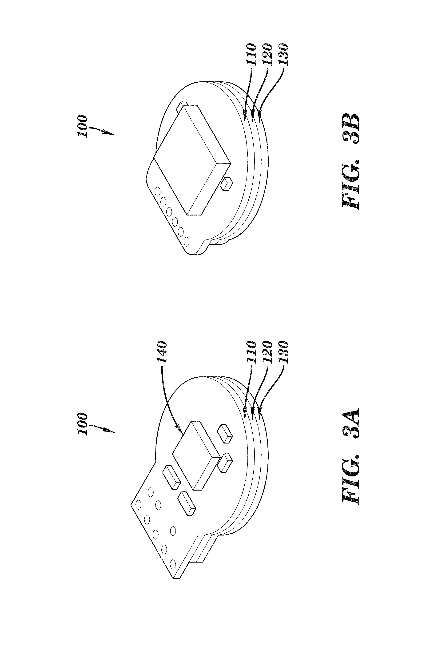
FIGS. 3A and 3B show diagrammatic views of a perspiration sensor according to some embodiments of the invention.
FIG. 4 shows an exploded isometric top view of a perspiration sensor according to an embodiment of the invention.
FIG. 5 shows an exploded isometric bottom view of a perspiration sensor according to an embodiment of the invention.
FIG. 6A shows an exploded cross-section view of a perspiration sensor according to an embodiment of the invention.
FIG. 6B shows a cross-section view of an assembled perspiration sensor according to an embodiment of the invention shown in FIG. 6A.
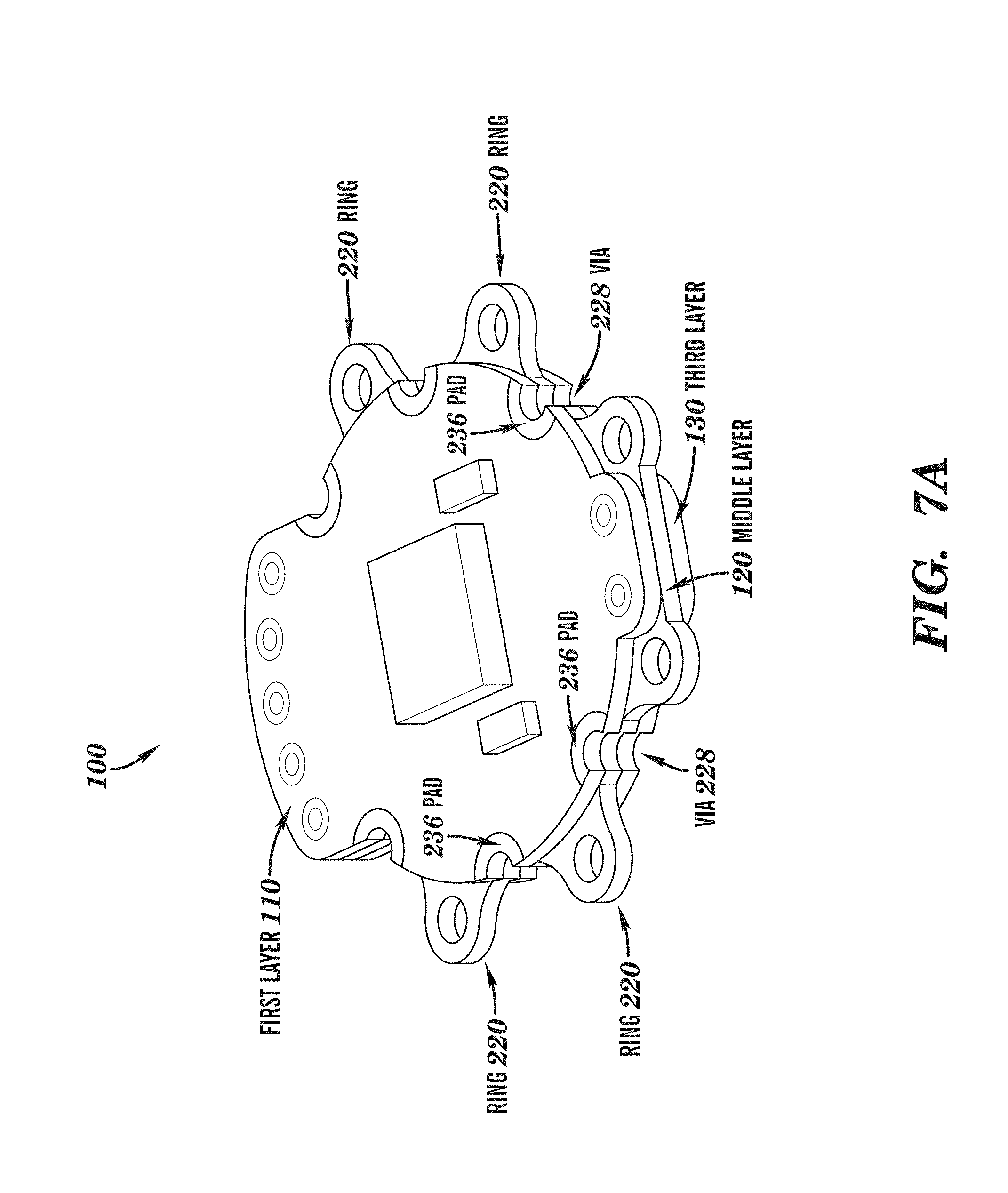
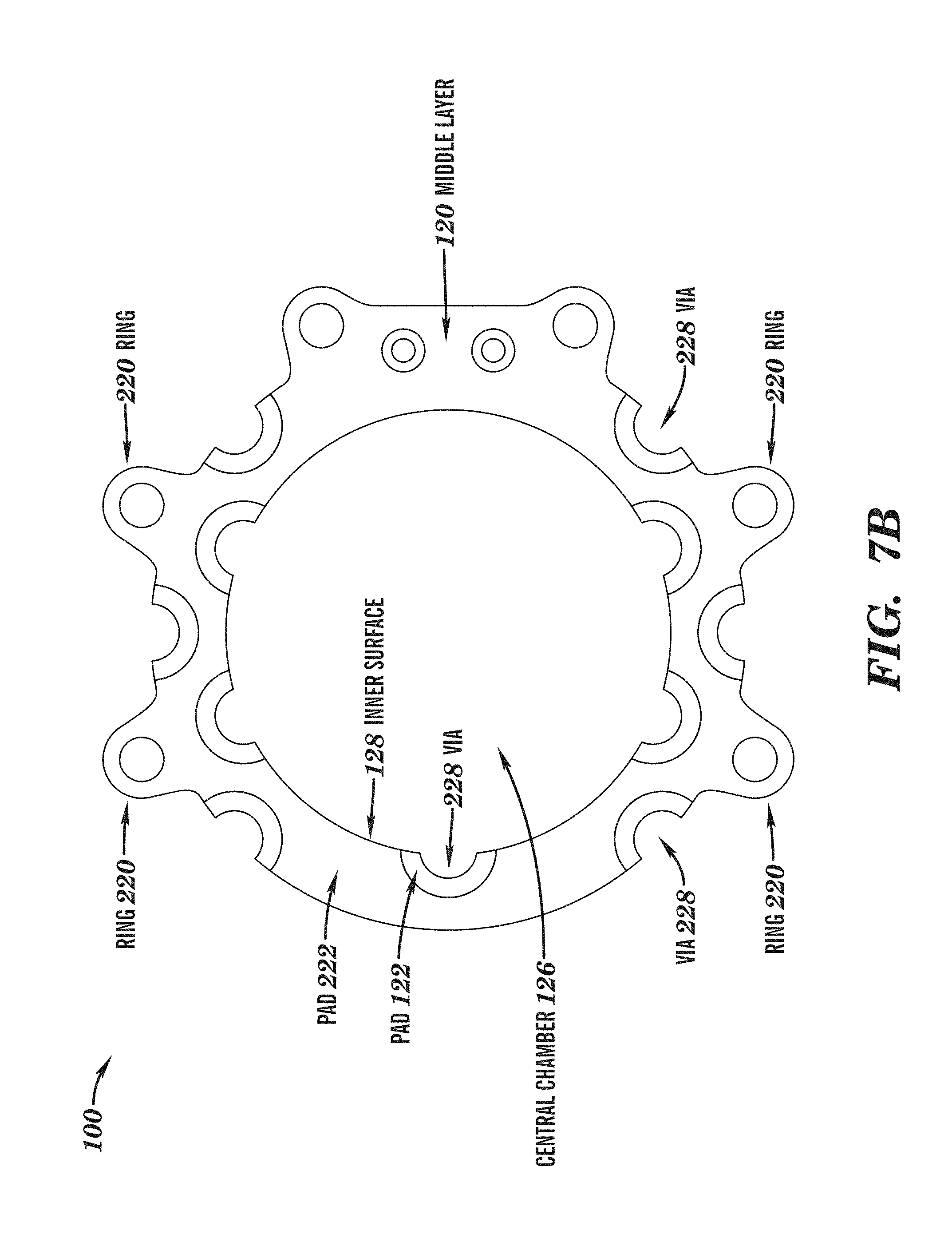
FIG. 7A shows a diagram of a perspiration sensor according to some embodiments of the invention, FIG. 7B shows a diagrammatic view of the middle layer according to an embodiment of the invention, and FIG. 7C shows a cutaway view of a perspiration sensor according to some embodiments of the invention with a portion of the encapsulation material removed.
FIGS. 8A and 8B show diagrams of dielectric material according to some embodiments of the invention.
FIGS. 9A and 9B show diagrams of electronic circuits for measuring the change in capacitance between the electrodes of a perspiration sensor according to some embodiments of the invention.
FIGS. 10A, 10B, 10C and 10D show graphs of performance data for 5 a perspiration sensor according to some embodiments of the invention.
DETAILED DESCRIPTION OF PREFERRED EMBODIMENTS
The present invention is directed to methods and systems for obtaining a quantitative measurement of moisture. One specific application for the invention includes the detection and measurement of perspiration. For purposes of illustration, the invention is described herein in the context of measuring perspiration, however, embodiments of the invention can be used to measure other sources of moisture.
In accordance with some embodiments of the invention, the perspiration sensor includes a pair of ground shielded parallel electrodes sandwiching a moisture absorbent dielectric material (e.g., a microfiber cloth) that forms a capacitor. The sensor allows perspiration to become absorbed by moisture absorbent dielectric material which changes the dielectric constant the dielectric material and is reflected in the measured capacitance of the electrode plates of the perspiration sensor. In accordance with some embodiments of the invention, the dielectric material can be electrically coupled (e.g., capacitively coupled) to the skin of the user to provide for more stable signal measurement. In accordance with some embodiments of the invention, the absorbent dielectric material can be weakly (e.g., 10 pF or less) but consistently (e.g., up to 10% variation) coupled through the skin to earth ground which is weakly coupled to signal ground of capacitance measuring circuit. The method includes providing a capacitor that includes an exposed dielectric material that can absorb moisture (e.g., perspiration) produced by the skin. As perspiration is released from the skin and becomes absorbed by the absorbent dielectric material, the dielectric properties of the material between the electrode plates change resulting in a change in the capacitance of the perspiration sensor. An internal or external measurement component can be connected to the electrodes of the capacitor to measure the changes in capacitance of the perspiration sensor.
The dielectric properties of perspiration closely resemble that of saline which in turn closely resemble that of water. The dielectric constant of water is about 80 times that of air. An air capacitor formed by two parallel plates will increase capacitance significantly when air is replaced with water, saline, or perspiration. The approximate capacitance C of the parallel plates can be determined by
.times..times. ##EQU00001## where A is the area of the electrode plate, d is the distance between the plates; .epsilon..sub.0 is the dielectric constant of free space and .epsilon..sub.r is the relative dielectric constant of the material between the plates.
In accordance with the invention, the dielectric material can be selected to rapidly absorb the perspiration. In accordance with some embodiments of the invention, the dielectric material can have predefined wicking or absorbency properties that provide a desired level of perspiration absorption. In operation, the dielectric material is initially in a dry state and has dielectric properties similar to air and produces an initial capacitance level. As the dielectric material is exposed to moisture (e.g., perspiration) the moisture rapidly replaces the air, changing the dielectric properties of the dielectric material and the measured capacitance level of the sensor.
In accordance with some embodiments of the invention, the absorbent dielectric material can include a tufted microfiber cloth. This material has been found to have improved capillary suction and to diffuse perspiration faster and more uniformly than other materials as well as provides higher absorption densities. Other absorbent materials, such as cellulose paper, foamy elastomers, cotton, wool, air, and moisture wicking materials, can be used. The absorbent dielectric material can be configured to have a large surface area to volume ratio of the material that results in capillary suction causing the air filled space to become filled with environmental moisture or perspiration. A capacitance measuring circuit can be provided onboard or in close proximity to the capacitor sensor to minimize noise and convert the capacitance to a digital signal for transmission to a connected device.
FIGS. 1, 3A and 3B shows a moisture or perspiration sensor 100 according to various embodiments of the invention with the encapsulating polymer removed to provide a better view of the structure of the device. FIGS. 2A and 2B show diagrammatic views of a perspiration sensor 200 according to embodiments of the invention encapsulated in an encapsulating material, such as polymer material (e.g., silicone, PDMS, polyimide, TPE, PET, PVC, and MMA). The perspiration sensor 200 can include channels 210 that serve to guide moisture, such as perspiration, toward inlets in the perspiration sensor 200.
As shown in FIGS. 3A and 3B, the perspiration sensor 100 can be constructed from two or more layers of insulating or dielectric material (e.g., a first layer 110, a second layer 120 and the third layer 130). In accordance with some embodiments of the invention, each layer can include a non-conductive substrate (e.g. FR4 epoxy fiberglass, PDMS, or polyimide) having a conductive layer (e.g., copper and/or tin) on one or both surfaces of the substrate, such as a printed circuit board (PCB) or flexible PCB. In accordance with some embodiments of the invention, each layer can include a protective and/or insulating coating (e.g., solder mask coating) covering a portion or all of each surface of each layer. Each of the layers that make up the perspiration sensor 100 can be bonded together using well known adhesives (e.g., epoxy, polyimide, and/or silicone based adhesives). The surfaces of at least some of the layers can include exposed pads enabling electronic components such as integrated circuits, discrete components (e.g., resistors, capacitors, diodes and other passive devices) to soldered in place. The layers can also include vias or plated through holes that allow circuit traces to extend through the layer can make contact with circuit traces of the other layers. In accordance with some embodiments of the invention, some or all of the layers can include castellated vias on or extending from the external edges that provide for mechanical alignment and enable low temperature fabrication--the castellated vias are positioned away from central chamber and can be soldered without fear of melting or otherwise damaging the absorbent dielectric material.
FIG. 4 shows an exploded view of a perspiration sensor 100 according to some embodiments of the invention. In this embodiment, the perspiration sensor 100 includes a first or top layer 110, a second or middle layer 120 and the third or bottom layer 130. The first layer 110 includes a first electrode 112 on the underside of the first layer (hidden from view in FIG. 4, but shown in FIG. 5). The first layer 110 can also include circuit traces that enable a sensing integrated circuit 140 to soldered in place and electrically connected to the first electrode 112 and second electrode 134 and wires (not shown) that connect the perspiration sensor 100 to other devices. The third layer 130 includes one or more inlets 132 and the second electrode 134. The third layer 130 can also include a skin electrode 136 (hidden from view in FIG. 4, but shown in FIG. 5) and an adhesive material covering the skin electrode 136 to adhere the perspiration sensor 100 to a surface such as a skin surface. The second layer 120 forms a ring 122 that at least partially surrounds or encloses the dielectric material 124 in the dielectric space defined by the central chamber 26. When the three layers are bonded together, they form a central chamber 126 which encloses the dielectric material 124 (e.g., the moisture absorbent material). In accordance with some embodiments of the invention, the thickness of each layer can be selected to minimize the overall thickness of the sensor to improve user comfort. Thus, the first layer 110 and the third layer 130 can be thicker or thinner than the middle layer 120. Alternatively, each of the layers can have the same or different thicknesses. In accordance with some embodiments, the sensor detection area, defined by the inlets 132 can cover an area of 1 cubic centimeter and provide an average pore density of 50 pores (e.g., in the arm pit).
FIG. 5 shows an exploded bottom view of the perspiration sensor 100 (e.g., showing the third layer 130 on top). As shown in FIG. 5, the third layer 130 can include a skin electrode 136 on the outer surface thereof. The skin electrode 136 can be provided in the form of a ring, as shown, or as a set of interconnected contact points over the outer surface of the third layer 130. In accordance with some embodiments, the skin electrode 136 can be electrically connected to the dielectric material 124 in the central chamber 126 of the perspiration sensor 100 by extending circuit traces around or vias through the third layer 130 to the middle layer 120 and in contact with the dielectric material 124. In accordance with other embodiments, the skin electrode 136 can be electrically connected to the dielectric material 124 by circuit traces or wires that extend from the inner surface of the third layer 130 into the central chamber 126. The skin electrode 136 can be covered with a solder mask or other insulating material (e.g., skin adhesive tape). When the perspiration sensor 100 is adhered or placed in contact with the skin, the skin electrode 136 capacitively couples the dielectric material 124 to the skin.
FIG. 6A shows an exploded cross-section view and FIG. 6B shows an assembled cross-section view of a perspiration sensor 100 according to some embodiments of the invention. In this embodiment, an adhesive layer 150 adheres the third layer 130 of the perspiration sensor 100 to the surface of the skin 160 enabling the device to measure perspiration. The perspiration sensor 100 includes a first layer 110, second layer 120 and a third layer 130. The first electrode 112 is formed on the inner surface of the first layer 110 and the second electrode 134 is formed on the inner surface of the third layer 130. A mask 114 on the first layer and a mask 138 on third layer can be included to electrically insulate the first electrode 112 and the second electrode 134 from the dielectric material 124 while enabling the dielectric material 124 to be in intimate contact with the first electrode 112 and the second electrode 134 while preventing the moistened dielectric material from shorting the first electrode to the second electrode. The insulating masks 114 and 138 can be formed from any solder mask insulating material (e.g., a layer or film of epoxy or UV cured polymer or resin). The second layer 120 is bonded between the first layer 110 and the third layer 130 supporting the first electrode 112 at predefined distance with respect to the second electrode 134 and forming the central chamber 126 that encloses the moisture absorbent dielectric material 124. The third layer 130 includes one or more inlets 132 that allow the moisture (e.g., perspiration) to enter the central chamber 126 and become absorbed by the moisture absorbent dielectric material 124 as well as to allow air initially contained within the moisture absorbent dielectric material 124 to escape. As shown in FIG. 6B, when the layers are bonded together, the moisture absorbent dielectric material 124 can become partially or fully extruded through the inlets 132 to facilitate moisture absorption. In accordance with some embodiments, an outlet can be provided through the middle layer 120 or the first layer 110 to enable air initially contained within the moisture absorbent dielectric material 124 to escape. The perspiration from skin 160 enters the inlets 132 and is absorbed by the moisture absorbent dielectric material 124.
As shown in FIGS. 6A and 6B, the third layer 130 includes one or more vias or plated through holes that electrically connect the skin electrode 136 to the inner surface of the third layer 130 and after assembly, make electrical contact with an inner trace or electrode 122 on the middle layer 120. The inner electrode 122 can extend into the central chamber 126 and make contact with the moisture absorbent dielectric material 124. In some embodiments of the invention, all or a portion of the inner surface 128 of the middle layer 120 can include a conductive material (e.g., copper or tin) that makes contact with the moisture absorbent dielectric material 124.
FIG. 7A shows a perspective view of a perspiration sensor 100 according to some embodiments of the invention and FIG. 7B shows a diagrammatic view of the middle layer 120. In these embodiments, the first layer 110, the middle layer 120 and the third layer 130 each include pads 122, 236 and plated through holes or partial holes or vias 228 that enable circuit traces to extend between layers. Solder can be applied to the plated through holes or vias 228 to create a physical connection between the layers and an electrical connection between the pads 122, 236 on the outside surfaces of the sensor 100 and the dielectric space defined by the central chamber 126. In some embodiments, the third layer 130 can include pads (not shown) that serve as the skin electrode 136 and can be electrically connected to circuit traces on the middle layer 120 and the first layer 110 soldering together the vias 228. Similar vias 226 can be provided on the inner surface of the middle layer 120 and connected by circuit traces 222 to one or more of the vias 228 to provide an electrical connection between the skin electrode 136 and the moisture absorbent dielectric material 124.
In accordance with some embodiments of the invention, the perspiration sensor 100 can also include one or more anchor rings 220 that project from the peripheral edge of the device as shown in FIGS. 7A and 7B. The anchor rings 220 serve to provide features in the peripheral structure of the sensor device to aid in anchoring the device in the encapsulating material such as silicone, PDMS, polyimide during assembly. FIG. 7C shows a partially cut away view of a perspiration sensor 100 according to some embodiments of the invention. In this embodiment, the vias 228 are shown along the outer surface of the sensor 100 and the anchor rings 220 are shown extending from the outer peripheral surface of the sensor 100. In some embodiments, the encapsulating material 205 can at least partially extend into the openings of the anchor rings 220.
FIGS. 8A and 8B show photos and diagrams of microfibers. Microfiber based materials provide for improved absorption of moisture. In some embodiments, the microfibers can be split microfibers which have an X or asterisk shaped cross-section as shown in FIG. 8A. This structure results in the formation of microchannels in the fibers that help absorb moisture (e.g., by capillary action) better than regular solid fibers. As shown in FIG. 8B, these microfibers can be loosely woven into a tufted cloth that provides good absorption of moisture.
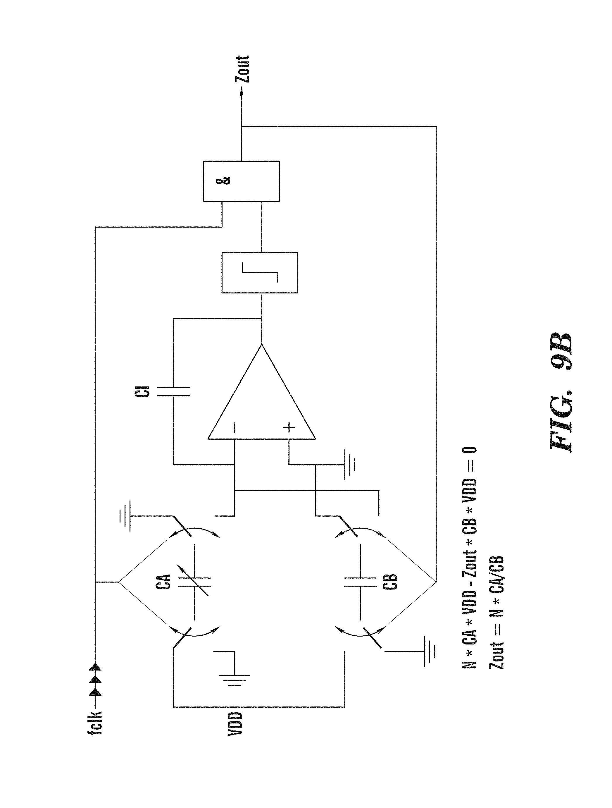
In accordance with some embodiments, the perspiration sensor can include a capacitive sensor signal measuring integrated circuit that accurately measures the capacitance or capacitive signal and converts it to a digital signal for transmission to a remote device. In accordance with some embodiments of the invention, the capacitive sensor signal measuring integrated circuit can include a ZSSC3123 integrated circuit (ZMDI, Dresden, Germany and Milpitas, Calif.). FIG. 9A shows a block diagram of the integrated circuit. FIG. 9B shows a diagram of a charge balancing circuit for converting the analog capacitance signal to a digital signal. The circuit includes a 1st order charge-balancing capacitance-to-digital converter. Capacitor CB can be a fixed reference capacitor internal to the IC itself. The measurement determines the amount of time it takes each cycle to charge and discharge the reference capacitor. The capacitor CA is driven by a square wave voltage with excitation frequency in the 100 kHz range to prevent aging effects that occur when driven by a DC signal. The output signal generated by this circuit is a ratio of sensor capacitance to reference capacitance.
FIG. 10A shows a sensitivity graph for a capacitive perspiration sensor according to the invention. As shown in FIG. 10A, the sensitivity is higher (e.g., 2.5 pF/.mu.L) at lower moisture levels and decreases (e.g., to 1.2 pF/.mu.L) as the level of moisture increases.
FIG. 10B shows a responsivity graph for a capacitive perspiration sensor according to the invention. The graph in FIG. 10B shows the response of the capacitive perspiration sensor according to the invention over time at 5 different moisture levels (e.g., 0.1 .mu.L, 0.2 .mu.L, 0.5 .mu.L, 1.0 .mu.L, and 2.0 .mu.L).
FIG. 10C shows the effect of shielding (e.g., capacitive coupling the dielectric to the skin) on a capacitive perspiration sensor according to the invention. As shown in FIG. 10C, an unshielded capacitive perspiration sensor exhibits signal spikes upon contact whereas the shielded capacitive perspiration sensor according to the invention does not.
FIG. 10D shows a comparison of the range and sensitivity of shielded and unshielded capacitive perspiration sensors according to the invention. As shown in FIG. 10D, the shielded sensor has approximately the same range and sensitivity as an unshielded sensor.
In accordance with some embodiments of the invention, the perspiration sensor can be part of system that quantitatively measures perspiration of a user in real time. The sensor can be connected to a data-logging hub (e.g. BioStamp TM by MC10 Inc., a smartphone or data recorder). The perspiration sensor can measure a change in capacitance over time and calculate perspiration moisture volume using a predetermined calibrated curve. The data logging hub can include a computer processor and associated memory that can communicate with the perspiration sensor to receive sensor data. The data logging hub can include additional wired or wireless communication components to enable the sensor data to be stored in a remote database or processed by a remote data processing system.
While some embodiments of the present invention are described in the context of a perspiration sensor, the invention can be used for measuring moisture in other applications. In some embodiments, the moisture sensor can be used to measure perspiration to test the efficacy of anti-perspirant products. In other applications, the moisture sensor can be installed in a helmet worn by an athlete, a soldier or a fighter pilot as well as other areas of the body to provide continuous physiological monitoring, for example, for health, wellness, hydration and/or stress monitoring. In accordance with some embodiments, the central chamber or an adjacent collection chamber can include analyte sensors and/or assays to detecting the presence and/or quantity of components of the absorbed perspiration. For example, a sodium sensor can be included for diagnosis of cystic fibrosis.
Other embodiments are within the scope and spirit of the invention. For example, due to the nature of hardware and software, functions described above can be implemented using software, hardware, firmware, hardwiring, or combinations of any of these. Features implementing functions may also be physically located at various positions, including being distributed such that portions of functions are implemented at different physical locations.
Further, while the description above refers to the invention, the description may include more than one invention.
* * * * *
D00000
D00001
D00002
D00003
D00004
D00005
D00006
D00007
D00008
D00009
D00010
D00011
D00012

D00013

D00014
D00015

D00016

D00017

D00018

M00001

XML
uspto.report is an independent third-party trademark research tool that is not affiliated, endorsed, or sponsored by the United States Patent and Trademark Office (USPTO) or any other governmental organization. The information provided by uspto.report is based on publicly available data at the time of writing and is intended for informational purposes only.
While we strive to provide accurate and up-to-date information, we do not guarantee the accuracy, completeness, reliability, or suitability of the information displayed on this site. The use of this site is at your own risk. Any reliance you place on such information is therefore strictly at your own risk.
All official trademark data, including owner information, should be verified by visiting the official USPTO website at www.uspto.gov. This site is not intended to replace professional legal advice and should not be used as a substitute for consulting with a legal professional who is knowledgeable about trademark law.