Self-authenticating electrocardiography monitoring circuit
Felix , et al. Sep
U.S. patent number 10,398,334 [Application Number 15/602,007] was granted by the patent office on 2019-09-03 for self-authenticating electrocardiography monitoring circuit. This patent grant is currently assigned to Bardy Diagnostics, Inc.. The grantee listed for this patent is Bardy Diagnostics, Inc.. Invention is credited to Gust H. Bardy, Jon Mikalson Bishay, Jason Felix.


| United States Patent | 10,398,334 |
| Felix , et al. | September 3, 2019 |
Self-authenticating electrocardiography monitoring circuit
Abstract
Physiological monitoring can be provided through a wearable monitor that includes two components, a flexible extended wear electrode patch and a removable reusable monitor recorder. The wearable monitor sits centrally (in the midline) on the patient's chest along the sternum oriented top-to-bottom. The placement of the wearable monitor in a location at the sternal midline (or immediately to either side of the sternum) benefits extended wear by removing the requirement that ECG electrodes be continually placed in the same spots on the skin throughout the monitoring period. Instead, the patient can place an electrode patch anywhere within the general region of the sternum. Ensuring that the quality level of ECG recording remains constant over an extended period of time is provided through self-authentication of electrode patches. The monitor recorder implements a challenge response scheme upon being connected to an electrode patch. Failing self-authentication, the monitor recorder signals an error condition.
| Inventors: | Felix; Jason (Vashon Island, WA), Bardy; Gust H. (Carnation, WA), Bishay; Jon Mikalson (Seattle, WA) | ||||||||||
|---|---|---|---|---|---|---|---|---|---|---|---|
| Applicant: |
|
||||||||||
| Assignee: | Bardy Diagnostics, Inc.
(Seattle, WA) |
||||||||||
| Family ID: | 52691530 | ||||||||||
| Appl. No.: | 15/602,007 | ||||||||||
| Filed: | May 22, 2017 |
Prior Publication Data
| Document Identifier | Publication Date | |
|---|---|---|
| US 20170251948 A1 | Sep 7, 2017 | |
Related U.S. Patent Documents
| Application Number | Filing Date | Patent Number | Issue Date | ||
|---|---|---|---|---|---|
| 14082066 | Nov 15, 2013 | 9655538 | |||
| 14080717 | Jan 17, 2017 | 9545204 | |||
| 14080725 | Nov 14, 2013 | 9730593 | |||
| 61882403 | Sep 25, 2013 | ||||
| Current U.S. Class: | 1/1 |
| Current CPC Class: | A61B 5/0006 (20130101); A61B 5/0022 (20130101); A61B 5/0402 (20130101); A61B 5/04325 (20130101); A61B 5/04085 (20130101); A61B 5/6823 (20130101); A61B 5/04087 (20130101); A61B 2562/08 (20130101) |
| Current International Class: | A61B 5/0402 (20060101); A61B 5/0432 (20060101); A61B 5/0408 (20060101); A61B 5/00 (20060101) |
References Cited [Referenced By]
U.S. Patent Documents
| 3215136 | November 1965 | Holter et al. |
| 3569852 | March 1971 | Berkovits |
| 3699948 | October 1972 | Ota et al. |
| 3718772 | February 1973 | Sanctuary |
| 3893453 | July 1975 | Goldberg |
| 4123785 | October 1978 | Cherry et al. |
| 4151513 | April 1979 | Menken et al. |
| 4328814 | May 1982 | Arkans |
| 4441500 | April 1984 | Sessions et al. |
| 4532934 | August 1985 | Kelen |
| 4546342 | October 1985 | Weaver et al. |
| 4550502 | November 1985 | Grayzel |
| 4580572 | April 1986 | Granek et al. |
| 4635646 | January 1987 | Gilles et al. |
| 4653022 | March 1987 | Koro |
| 4716903 | January 1988 | Hansen |
| 4809705 | March 1989 | Ascher |
| 4915656 | April 1990 | Alferness |
| 5007429 | April 1991 | Treatch et al. |
| 5025794 | June 1991 | Albert et al. |
| 5107480 | April 1992 | Naus |
| 5168876 | December 1992 | Quedens et al. |
| 5215098 | June 1993 | Steinhaus |
| 5231990 | August 1993 | Gauglitz |
| D341423 | November 1993 | Bible |
| 5263481 | November 1993 | Axelgaard |
| 5265579 | November 1993 | Ferrari |
| 5333615 | August 1994 | Craelius et al. |
| 5341806 | August 1994 | Gadsby et al. |
| 5348008 | September 1994 | Bornn et al. |
| 5355891 | October 1994 | Wateridge et al. |
| 5365934 | November 1994 | Leon et al. |
| 5365935 | November 1994 | Righter et al. |
| 5392784 | February 1995 | Gudaitis |
| D357069 | April 1995 | Plahn et al. |
| 5402780 | April 1995 | Faasse, Jr. |
| 5402884 | April 1995 | Gilman et al. |
| 5450845 | September 1995 | Axelgaard |
| 5451876 | September 1995 | Sendford et al. |
| 5458141 | October 1995 | Neil |
| 5473537 | December 1995 | Glazer et al. |
| 5483969 | January 1996 | Testerman et al. |
| 5511553 | April 1996 | Segalowitz |
| 5540733 | July 1996 | Testerman et al. |
| 5546952 | August 1996 | Erickson |
| 5549655 | August 1996 | Erickson |
| 5579919 | December 1996 | Gilman et al. |
| 5582181 | December 1996 | Ruess |
| D377983 | February 1997 | Sabri et al. |
| 5601089 | February 1997 | Bledsoe et al. |
| 5623935 | April 1997 | Faisandier |
| 5682901 | November 1997 | Kamen |
| 5697955 | December 1997 | Stolte |
| 5724967 | March 1998 | Venkatachalam |
| 5749902 | May 1998 | Olson et al. |
| 5788633 | August 1998 | Mahoney |
| 5817151 | October 1998 | Olson et al. |
| 5819741 | October 1998 | Karlsson et al. |
| 5850920 | December 1998 | Gilman et al. |
| D407159 | March 1999 | Roberg |
| 5876351 | March 1999 | Rohde |
| 5906583 | May 1999 | Rogel |
| 5951598 | September 1999 | Bishay et al. |
| 5957857 | September 1999 | Hartley |
| 5984102 | November 1999 | Tay |
| 6032064 | February 2000 | Devlin et al. |
| 6038469 | March 2000 | Karlsson et al. |
| 6101413 | August 2000 | Olson et al. |
| 6115638 | September 2000 | Groenke |
| 6117077 | September 2000 | Del Mar et al. |
| 6134479 | October 2000 | Brewer et al. |
| 6148233 | November 2000 | Owen et al. |
| 6149602 | November 2000 | Arcelus |
| 6149781 | November 2000 | Forand |
| 6188407 | February 2001 | Smith et al. |
| D443063 | May 2001 | Pisani et al. |
| 6245025 | June 2001 | Torok et al. |
| 6246330 | June 2001 | Nielsen |
| 6249696 | June 2001 | Olson et al. |
| D445507 | July 2001 | Pisani et al. |
| 6269267 | July 2001 | Bardy et al. |
| 6272385 | August 2001 | Bishay et al. |
| 6298255 | October 2001 | Cordero |
| 6301502 | October 2001 | Owen et al. |
| 6304773 | October 2001 | Taylor et al. |
| 6304780 | October 2001 | Owen et al. |
| 6304783 | October 2001 | Lyster et al. |
| 6374138 | April 2002 | Owen et al. |
| 6381482 | April 2002 | Jayaraman et al. |
| 6416471 | July 2002 | Kumar et al. |
| 6418342 | July 2002 | Owen et al. |
| 6424860 | July 2002 | Karlsson et al. |
| 6427083 | July 2002 | Owen et al. |
| 6427085 | July 2002 | Boon et al. |
| 6454708 | September 2002 | Ferguson et al. |
| 6456872 | September 2002 | Faisandier |
| 6463320 | October 2002 | Xue et al. |
| 6546285 | April 2003 | Owen et al. |
| 6605046 | August 2003 | Del Mar |
| 6607485 | August 2003 | Bardy |
| 6611705 | August 2003 | Hopman et al. |
| 6671545 | December 2003 | Fincke |
| 6671547 | December 2003 | Lyster et al. |
| 6694186 | February 2004 | Bardy |
| 6704595 | March 2004 | Bardy |
| 6705991 | March 2004 | Bardy |
| 6719701 | April 2004 | Lade |
| 6754523 | June 2004 | Toole |
| 6782293 | August 2004 | Dupelle et al. |
| 6856832 | February 2005 | Matsumura et al. |
| 6860897 | March 2005 | Bardy |
| 6866629 | March 2005 | Bardy |
| 6887201 | May 2005 | Bardy |
| 6893397 | May 2005 | Bardy |
| 6904312 | June 2005 | Bardy |
| 6908431 | June 2005 | Bardy |
| 6913577 | July 2005 | Bardy |
| 6944498 | September 2005 | Owen et al. |
| 6960167 | November 2005 | Bardy |
| 6970731 | November 2005 | Jayaraman et al. |
| 6978169 | December 2005 | Guerra |
| 6993377 | January 2006 | Flick et al. |
| 7020508 | March 2006 | Stivoric et al. |
| 7027864 | April 2006 | Snyder et al. |
| 7065401 | June 2006 | Worden |
| 7085601 | August 2006 | Bardy et al. |
| 7104955 | September 2006 | Bardy |
| 7134996 | November 2006 | Bardy |
| 7137389 | November 2006 | Berthon-Jones |
| 7147600 | December 2006 | Bardy |
| 7215991 | May 2007 | Besson et al. |
| 7248916 | July 2007 | Bardy |
| 7257438 | August 2007 | Kinast |
| 7277752 | October 2007 | Matos |
| 7294108 | November 2007 | Bomzin et al. |
| D558882 | January 2008 | Brady |
| 7328061 | February 2008 | Rowlandson et al. |
| 7412395 | August 2008 | Rowlandson et al. |
| 7429938 | September 2008 | Corndorf |
| 7552031 | June 2009 | Vock et al. |
| D606656 | December 2009 | Kobayashi et al. |
| 7706870 | April 2010 | Shieh et al. |
| 7756721 | July 2010 | Falchuk et al. |
| 7787943 | August 2010 | McDonough |
| 7874993 | January 2011 | Bardy |
| 7881785 | February 2011 | Nassif et al. |
| D639437 | June 2011 | Bishay et al. |
| 7959574 | June 2011 | Bardy |
| 8108035 | January 2012 | Bharmi |
| 8116841 | February 2012 | Bly et al. |
| 8135459 | March 2012 | Bardy et al. |
| 8150502 | April 2012 | Kumar et al. |
| 8160682 | April 2012 | Kumar et al. |
| 8172761 | May 2012 | Rulkov et al. |
| 8180425 | May 2012 | Selvitelli et al. |
| 8200320 | June 2012 | Kovacs |
| 8231539 | July 2012 | Bardy |
| 8231540 | July 2012 | Bardy |
| 8239012 | August 2012 | Felix et al. |
| 8249686 | August 2012 | Libbus et al. |
| 8260414 | September 2012 | Nassif et al. |
| 8266008 | September 2012 | Siegal et al. |
| 8277378 | October 2012 | Bardy |
| 8285356 | October 2012 | Bly et al. |
| 8285370 | October 2012 | Felix et al. |
| 8308650 | November 2012 | Bardy |
| 8366629 | February 2013 | Bardy |
| 8374688 | February 2013 | Libbus et al. |
| 8412317 | April 2013 | Mazar |
| 8460189 | June 2013 | Libbus et al. |
| 8473047 | June 2013 | Chakravarthy et al. |
| 8478418 | July 2013 | Fahey |
| 8538503 | September 2013 | Kumar et al. |
| 8554311 | October 2013 | Warner et al. |
| 8560046 | October 2013 | Kumar et al. |
| 8591430 | November 2013 | Amurthur et al. |
| 8594763 | November 2013 | Bibian et al. |
| 8600486 | December 2013 | Kaib et al. |
| 8613708 | December 2013 | Bishay et al. |
| 8613709 | December 2013 | Bishay et al. |
| 8620418 | December 2013 | Kuppuraj et al. |
| 8626277 | January 2014 | Felix et al. |
| 8628020 | January 2014 | Beck |
| 8668653 | March 2014 | Nagata et al. |
| 8684925 | April 2014 | Manicka et al. |
| 8688190 | April 2014 | Libbus et al. |
| 8718752 | May 2014 | Libbus et al. |
| 8744561 | June 2014 | Fahey |
| 8774932 | July 2014 | Fahey |
| 8790257 | July 2014 | Libbus et al. |
| 8790259 | July 2014 | Katra et al. |
| 8795174 | August 2014 | Manicka et al. |
| 8798729 | August 2014 | Kaib et al. |
| 8798734 | August 2014 | Kuppuraj et al. |
| 8818478 | August 2014 | Scheffler et al. |
| 8818481 | August 2014 | Bly et al. |
| 8823490 | September 2014 | Libbus et al. |
| 8938287 | January 2015 | Felix et al. |
| 8965492 | February 2015 | Baker et al. |
| 9066664 | June 2015 | Karjalainen |
| 9155484 | October 2015 | Baker et al. |
| 9204813 | December 2015 | Kaib et al. |
| 9241649 | January 2016 | Kumar et al. |
| 9259154 | February 2016 | Miller et al. |
| 9277864 | March 2016 | Yang et al. |
| 9339202 | May 2016 | Brockway et al. |
| 9414786 | August 2016 | Brockway et al. |
| 9439566 | September 2016 | Arne et al. |
| 9603542 | March 2017 | Veen et al. |
| 9655538 | May 2017 | Felix |
| 9700222 | July 2017 | Quinlan et al. |
| 9770182 | September 2017 | Bly et al. |
| 10034614 | July 2018 | Edic et al. |
| 10045708 | August 2018 | Dusan |
| 10049182 | August 2018 | Chefles et al. |
| 2002/0013538 | January 2002 | Teller |
| 2002/0013717 | January 2002 | Ando et al. |
| 2002/0016798 | February 2002 | Sakai et al. |
| 2002/0103422 | August 2002 | Harder et al. |
| 2002/0109621 | August 2002 | Khair et al. |
| 2002/0120310 | August 2002 | Linden et al. |
| 2002/0128686 | September 2002 | Minogue et al. |
| 2002/0184055 | December 2002 | Naghavi et al. |
| 2002/0193668 | December 2002 | Munneke |
| 2003/0004547 | January 2003 | Owen et al. |
| 2003/0073916 | April 2003 | Yonce |
| 2003/0083559 | May 2003 | Thompson |
| 2003/0097078 | May 2003 | Maeda |
| 2003/0139785 | July 2003 | Riff et al. |
| 2003/0176802 | September 2003 | Galen et al. |
| 2003/0211797 | November 2003 | Hill et al. |
| 2004/0008123 | January 2004 | Carrender |
| 2004/0019288 | January 2004 | Kinast |
| 2004/0034284 | February 2004 | Aversano et al. |
| 2004/0049132 | March 2004 | Barron et al. |
| 2004/0073127 | April 2004 | Istvan et al. |
| 2004/0087836 | May 2004 | Green et al. |
| 2004/0088019 | May 2004 | Rueter et al. |
| 2004/0093192 | May 2004 | Hasson et al. |
| 2004/0148194 | July 2004 | Wellons et al. |
| 2004/0163034 | August 2004 | Colbath et al. |
| 2004/0167416 | August 2004 | Lee |
| 2004/0207530 | October 2004 | Nielsen |
| 2004/0210165 | October 2004 | Marmaropoulos et al. |
| 2004/0236202 | November 2004 | Burton |
| 2004/0243435 | December 2004 | Williams |
| 2004/0256453 | December 2004 | Lammle |
| 2004/0260188 | December 2004 | Syed et al. |
| 2004/0260192 | December 2004 | Yamamoto |
| 2005/0010139 | January 2005 | Aminian et al. |
| 2005/0096717 | May 2005 | Bishay et al. |
| 2005/0108055 | May 2005 | Ott et al. |
| 2005/0151640 | July 2005 | Hastings |
| 2005/0154267 | July 2005 | Bardy |
| 2005/0182308 | August 2005 | Bardy |
| 2005/0182309 | August 2005 | Bardy |
| 2005/0215918 | September 2005 | Frantz et al. |
| 2005/0222513 | October 2005 | Hadley et al. |
| 2005/0228243 | October 2005 | Bardy |
| 2005/0245839 | November 2005 | Stivoric et al. |
| 2005/0275416 | December 2005 | Hervieux et al. |
| 2006/0025696 | February 2006 | Kurzweil et al. |
| 2006/0025824 | February 2006 | Freeman et al. |
| 2006/0030767 | February 2006 | Lang et al. |
| 2006/0030904 | February 2006 | Quiles |
| 2006/0041201 | February 2006 | Behbehani et al. |
| 2006/0084883 | April 2006 | Linker |
| 2006/0122469 | June 2006 | Martel |
| 2006/0124193 | June 2006 | Orr et al. |
| 2006/0224072 | October 2006 | Shennib |
| 2006/0229522 | October 2006 | Barr |
| 2006/0235320 | October 2006 | Tan et al. |
| 2006/0253006 | November 2006 | Bardy |
| 2006/0264730 | November 2006 | Stivoric |
| 2006/0264767 | November 2006 | Shennib |
| 2007/0003115 | January 2007 | Patton et al. |
| 2007/0038057 | February 2007 | Nam et al. |
| 2007/0050209 | March 2007 | Yered |
| 2007/0078324 | April 2007 | Wijisiriwardana |
| 2007/0078354 | April 2007 | Holland |
| 2007/0088406 | April 2007 | Bennett et al. |
| 2007/0089800 | April 2007 | Sharma |
| 2007/0093719 | April 2007 | Nichols, Jr. et al. |
| 2007/0100248 | May 2007 | Van Dam et al. |
| 2007/0100667 | May 2007 | Bardy |
| 2007/0123801 | May 2007 | Goldberger et al. |
| 2007/0131595 | June 2007 | Jansson et al. |
| 2007/0136091 | June 2007 | McTaggart |
| 2007/0179357 | August 2007 | Bardy |
| 2007/0185390 | August 2007 | Perkins et al. |
| 2007/0203415 | August 2007 | Bardy |
| 2007/0203423 | August 2007 | Bardy |
| 2007/0208232 | September 2007 | Kovacs |
| 2007/0208233 | September 2007 | Kovacs |
| 2007/0208266 | September 2007 | Hadley |
| 2007/0225611 | September 2007 | Kumar et al. |
| 2007/0244405 | October 2007 | Xue et al. |
| 2007/0249946 | October 2007 | Kumar et al. |
| 2007/0255153 | November 2007 | Kumar et al. |
| 2007/0265510 | November 2007 | Bardy |
| 2007/0276270 | November 2007 | Tran |
| 2007/0276275 | November 2007 | Proctor et al. |
| 2007/0293738 | December 2007 | Bardy |
| 2007/0293739 | December 2007 | Bardy |
| 2007/0293740 | December 2007 | Bardy |
| 2007/0293741 | December 2007 | Bardy |
| 2007/0293772 | December 2007 | Bardy |
| 2007/0299325 | December 2007 | Farrell et al. |
| 2007/0299617 | December 2007 | Willis |
| 2008/0027339 | January 2008 | Nagai et al. |
| 2008/0051668 | February 2008 | Bardy |
| 2008/0058661 | March 2008 | Bardy |
| 2008/0088467 | April 2008 | Al-Ali |
| 2008/0091097 | April 2008 | Linti et al. |
| 2008/0108890 | May 2008 | Teng |
| 2008/0114232 | May 2008 | Gazit |
| 2008/0139953 | June 2008 | Baker |
| 2008/0143080 | June 2008 | Burr |
| 2008/0177168 | July 2008 | Callahan et al. |
| 2008/0194927 | August 2008 | KenKnight et al. |
| 2008/0208009 | August 2008 | Shklarski |
| 2008/0208014 | August 2008 | KenKnight et al. |
| 2008/0284599 | November 2008 | Zdeblick et al. |
| 2008/0288026 | November 2008 | Cross |
| 2008/0294024 | November 2008 | Cosentino et al. |
| 2008/0306359 | December 2008 | Zdeblick et al. |
| 2008/0312522 | December 2008 | Rowlandson |
| 2009/0012412 | January 2009 | Wesel |
| 2009/0012979 | January 2009 | Bateni et al. |
| 2009/0054952 | February 2009 | Glukhovsky et al. |
| 2009/0062897 | March 2009 | Axelgaard |
| 2009/0069867 | March 2009 | KenKnight et al. |
| 2009/0073991 | March 2009 | Landrum et al. |
| 2009/0076336 | March 2009 | Mazar et al. |
| 2009/0076341 | March 2009 | James et al. |
| 2009/0076342 | March 2009 | Amurthur et al. |
| 2009/0076343 | March 2009 | James et al. |
| 2009/0076346 | March 2009 | James et al. |
| 2009/0076349 | March 2009 | Libbus et al. |
| 2009/0076397 | March 2009 | Libbus et al. |
| 2009/0076401 | March 2009 | Mazar et al. |
| 2009/0076559 | March 2009 | Libbus et al. |
| 2009/0088652 | April 2009 | Tremblay |
| 2009/0112116 | April 2009 | Lee et al. |
| 2009/0131759 | May 2009 | Sims et al. |
| 2009/0156908 | June 2009 | Belalcazar et al. |
| 2009/0216132 | August 2009 | Orbach |
| 2009/0270708 | October 2009 | Shen et al. |
| 2009/0270747 | October 2009 | Van Dam et al. |
| 2009/0292194 | November 2009 | Libbus et al. |
| 2010/0007413 | January 2010 | Herleikson |
| 2010/0022897 | January 2010 | Parker et al. |
| 2010/0056881 | March 2010 | Libbus et al. |
| 2010/0081913 | April 2010 | Cross et al. |
| 2010/0174229 | July 2010 | Hsu et al. |
| 2010/0177100 | July 2010 | Carnes et al. |
| 2010/0185063 | July 2010 | Bardy |
| 2010/0185076 | July 2010 | Jeong et al. |
| 2010/0191154 | July 2010 | Berger et al. |
| 2010/0191310 | July 2010 | Bly |
| 2010/0223020 | September 2010 | Goetz |
| 2010/0234715 | September 2010 | Shin et al. |
| 2010/0234716 | September 2010 | Engel |
| 2010/0280366 | November 2010 | Ame et al. |
| 2010/0312188 | December 2010 | Robertson et al. |
| 2010/0324384 | December 2010 | Moon et al. |
| 2011/0021937 | January 2011 | Hugh |
| 2011/0054286 | March 2011 | Crosby et al. |
| 2011/0060215 | March 2011 | Tupin et al. |
| 2011/0066041 | March 2011 | Pandia et al. |
| 2011/0077497 | March 2011 | Oster et al. |
| 2011/0105861 | May 2011 | Derchak et al. |
| 2011/0144470 | June 2011 | Mazar et al. |
| 2011/0160548 | June 2011 | Forster et al. |
| 2011/0224564 | September 2011 | Moon et al. |
| 2011/0237922 | September 2011 | Parker, III et al. |
| 2011/0237924 | September 2011 | McGusty et al. |
| 2011/0245699 | October 2011 | Snell et al. |
| 2011/0245711 | October 2011 | Katra et al. |
| 2011/0288605 | November 2011 | Kaib et al. |
| 2012/0003933 | January 2012 | Baker et al. |
| 2012/0029306 | February 2012 | Paquet et al. |
| 2012/0029315 | February 2012 | Raptis et al. |
| 2012/0029316 | February 2012 | Raptis |
| 2012/0035432 | February 2012 | Katra et al. |
| 2012/0078127 | March 2012 | McDonald et al. |
| 2012/0088998 | April 2012 | Bardy et al. |
| 2012/0088999 | April 2012 | Bishay et al. |
| 2012/0089000 | April 2012 | Bishay et al. |
| 2012/0089001 | April 2012 | Bishay et al. |
| 2012/0089037 | April 2012 | Bishay et al. |
| 2012/0089412 | April 2012 | Bardy et al. |
| 2012/0089417 | April 2012 | Bardy et al. |
| 2012/0095352 | April 2012 | Tran |
| 2012/0101358 | April 2012 | Boettcher et al. |
| 2012/0101396 | April 2012 | Solosko |
| 2012/0165645 | June 2012 | Russel et al. |
| 2012/0306662 | June 2012 | Vosch et al. |
| 2012/0172695 | July 2012 | Ko et al. |
| 2012/0238910 | September 2012 | Nordstrom |
| 2012/0253847 | October 2012 | Dell'Anno et al. |
| 2012/0302906 | November 2012 | Felix et al. |
| 2012/0323132 | December 2012 | Warner et al. |
| 2012/0330126 | December 2012 | Hoppe et al. |
| 2013/0041272 | February 2013 | Guillen Arredondo et al. |
| 2013/0077263 | March 2013 | Oleson et al. |
| 2013/0079611 | March 2013 | Besko |
| 2013/0085347 | April 2013 | Manicka et al. |
| 2013/0085403 | April 2013 | Gunderson et al. |
| 2013/0096395 | April 2013 | Katra et al. |
| 2013/0116533 | May 2013 | Lian et al. |
| 2013/0123651 | May 2013 | Bardy |
| 2013/0158361 | June 2013 | Bardy |
| 2013/0197380 | August 2013 | Oral et al. |
| 2013/0225963 | August 2013 | Kodandaramaiah et al. |
| 2013/0225966 | August 2013 | Macia Barber et al. |
| 2013/0231947 | September 2013 | Shusterman |
| 2013/0243105 | September 2013 | Lei et al. |
| 2013/0274584 | October 2013 | Finlay et al. |
| 2013/0275158 | October 2013 | Fahey |
| 2013/0324809 | December 2013 | Lisogurski et al. |
| 2013/0324855 | December 2013 | Lisogurski et al. |
| 2013/0324856 | December 2013 | Lisogurski et al. |
| 2013/0325081 | December 2013 | Karst et al. |
| 2013/0325359 | December 2013 | Jarverud et al. |
| 2013/0331665 | December 2013 | Libbus et al. |
| 2013/0338448 | December 2013 | Libbus et al. |
| 2013/0338472 | December 2013 | Macia Barber et al. |
| 2014/0012154 | January 2014 | Mazar et al. |
| 2014/0056452 | February 2014 | Moss et al. |
| 2014/0088399 | March 2014 | Lian et al. |
| 2014/0140359 | May 2014 | Kalevo et al. |
| 2014/0180027 | June 2014 | Buller |
| 2014/0189928 | July 2014 | Oleson et al. |
| 2014/0206977 | July 2014 | Bahney et al. |
| 2014/0215246 | July 2014 | Lee et al. |
| 2014/0249852 | September 2014 | Proud |
| 2014/0296651 | October 2014 | Stone |
| 2014/0343390 | November 2014 | Berzowska et al. |
| 2014/0358193 | December 2014 | Lyons et al. |
| 2014/0364756 | December 2014 | Brockway et al. |
| 2015/0048836 | February 2015 | Guthrie et al. |
| 2015/0065842 | March 2015 | Lee et al. |
| 2015/0250422 | September 2015 | Bay |
| 2015/0257670 | September 2015 | Ortega et al. |
| 2015/0305676 | November 2015 | Shoshani |
| 2015/0359489 | December 2015 | Baudenbacher et al. |
| 2016/0135746 | May 2016 | Kumar et al. |
| 2016/0217691 | July 2016 | Kadobayashi et al. |
| 2019/0021671 | January 2019 | Kumar et al. |
| 19955211 | May 2001 | DE | |||
| 1859833 | Nov 2007 | EP | |||
| 2438851 | Apr 2012 | EP | |||
| 2438852 | Apr 2012 | EP | |||
| 2465415 | Jun 2012 | EP | |||
| 2589333 | May 2013 | EP | |||
| H06319711 | Nov 1994 | JP | |||
| H11188015 | Jul 1999 | JP | |||
| 2004129788 | Apr 2004 | JP | |||
| 2007082938 | Apr 2007 | JP | |||
| 2009219554 | Oct 2009 | JP | |||
| 199852463 | Nov 1998 | WO | |||
| 0078213 | Dec 2000 | WO | |||
| 2003032192 | Apr 2003 | WO | |||
| 2006009767 | Jan 2006 | WO | |||
| 2006014806 | Feb 2006 | WO | |||
| 2007066270 | Jun 2007 | WO | |||
| 2007092543 | Aug 2007 | WO | |||
| 2008010216 | Jan 2008 | WO | |||
| 2008057884 | May 2008 | WO | |||
| 2008092098 | Jul 2008 | WO | |||
| 2009036306 | Mar 2009 | WO | |||
| 2009036313 | Mar 2009 | WO | |||
| 2009036327 | Mar 2009 | WO | |||
| 2009112976 | Sep 2009 | WO | |||
| 2009112978 | Sep 2009 | WO | |||
| 2009112979 | Sep 2009 | WO | |||
| 2009142975 | Nov 2009 | WO | |||
| 2010066507 | Jun 2010 | WO | |||
| 2010105045 | Sep 2010 | WO | |||
| 2011047207 | Apr 2011 | WO | |||
| 2012140559 | Oct 2012 | WO | |||
| 2012146957 | Nov 2012 | WO | |||
Other References
|
15 of the Hottest Wearable Gadgets, URL <http://thehottestgadgets.com/2008/09/the-15-hottest-wearable-gadgets-- 001253> (Web page cached on Sep. 27, 2008). cited by applicant . Alivecor's Heart Monitor for iPhone Receives FDA Clearance, URL <http://www.businesswire.com/news/home/20121203005545/en/AliveCor%E2%8- 0%99s-Heart-Monitor-iPhone-Receives-FDA-Clearance#.U7rtq7FVTyF> (Dec. 3, 2012). cited by applicant . Bharadwaj et al., Techniques for Accurate ECG signal processing, EE Times, URL <www.eetimes.com/document.asp?doc_id=1278571> (Feb. 14, 2011). cited by applicant . Chen et al., "Monitoring Body Temperature of Newborn Infants At Neonatal Intensive Care Units Using Wearable Sensors," BodyNets 2010, Corfu Island, Greece. (Sep. 10, 2010). cited by applicant . Epstein, Andrew E. et al.; ACC/AHA/HRS 2008 Guidelines for Device-Based Therapy of Cardiac Rhythm Abnormalities. J. Am. Coll. Cardiol. 2008; 51; el-e62, 66 Pgs. cited by applicant . Fitbit automatically tracks your fitness and sleep, URL <http://www.fitbit.com/> (Web page cached on Sep. 10, 2008). cited by applicant . Smith, Kevin, "Jawbone Up VS. Fitbit Flex: Which Is the Best Fitness Band?" URL <http://www.businessinsider.com/fitbit-flex-vs-jawbone-up-2013-5?op=1&- gt; (Jun. 1, 2013). cited by applicant . Kligfield, Paul et al., Recommendations for the Standardization and Interpretation of the Electrocardiogram: Part I. J.Am.Coll. Cardiol; 2007; 49; 1109-27, 75 Pgs. cited by applicant . Lauren Gravitz, "When Your Diet Needs a Band-Aid,"Technology Review, MIT. (May 1, 2009). cited by applicant . Lieberman, Jonathan, "How Telemedicine Is Aiding Prompt ECG Diagnosis in Primary Care," British Journal of Community Nursing, vol. 13, No. 3, Mar. 1, 2008 (Mar. 1, 2008), pp. 123-126, XP009155082, ISSN: 1462-4753. cited by applicant . McManus et al., "A Novel Application for the Detection of an Irregular Pulse using an iPhone 4S in Patients with Atrial Fibrillation," vol. 10(3), pp. 315-319 (Mar. 2013). cited by applicant . Nike+ Fuel Band, URL <http://www.nike.com/us/en_us/c/nikeplus-fuelband> (Web page cached on Jan. 11, 2013). cited by applicant . P. Libby et al.,"Braunwald's Heart Disease--A Textbook of Cardiovascular Medicine," Chs. 11, pp. 125-148 and 12, pp. 149-193 (8th ed. 2008), American Heart Association. cited by applicant . Initial hands-on with Polar Loop activity tracker, URL <http://www.dcrainmaker.com/2013/09/polar-loop-firstlook.html> (Sep. 17, 2013). cited by applicant . Sittig et al., "A Computer-Based Outpatient Clinical Referral System," International Journal of Medical Informatics, Shannon, IR, vol. 55, No. 2, Aug. 1, 1999, pp. 149-158, XO004262434, ISSN: 1386-5056(99)00027-1. cited by applicant . Sleepview, URL <http://www.clevemed.com/sleepview/overview.shtml> (Web pages cached on Feb. 23, 2010, Dec. 29, 2012 and Sep. 4, 2013). cited by applicant . Actigraphy/ Circadian Rhythm SOMNOwatch, URL <http://www.somnomedics.eu/news-events/publications/somnowatchtm.html&- gt; (Web cached on Jan. 23, 2010). cited by applicant . Zio Event Card, URL <http://www.irhythmtech.com/zio-solution/zio-event/> (Web page cached on Mar. 11, 2013). cited by applicant . Zio Patch System, URL <http://www.irhythmtech.com/zio-solution/zio-system/index.html> (Web page cached on Sep. 8, 2013). cited by applicant . Saadi et al. "Heart Rhythm Analysis Using ECG Recorded With a Novel Sternum Based Patch Technology--A Pilot Study." Cardio technix 2013--Proceedings of the International Congress on Cardiovascular Technologies, Sep. 20, 2013. cited by applicant . Anonymous. "Omegawave Launches Consumer App 2.0 in U.S. Endurance Sportswire--Endurance Sportswire." Jul. 11, 2013. URL:http://endurancesportswire.com/omegawave-launches-consumer-app-2-0-in- -u-s/. cited by applicant . Chan et al. "Wireless Patch Sensor for Remote Monitoring of Heart Rate, Respiration, Activity, and Falls." pp. 6115-6118. 2013 35th Annual International Conference of the IEEE Engineering in Medical and Biology Society. Jul. 1, 2013. cited by applicant . Daoud et al. "Fall Detection Using Shimmer Technology and Multiresolution Analysis." Aug. 2, 2013. URL: https://decibel.ni.com/content/docs/Doc-26652. cited by applicant . Libbus. "Adherent Cardiac Monitor With Wireless Fall Detection for Patients With Unexplained Syncope." Abstracts of the First AMA-IEEE Medical Technology Conference on Individualized Healthcare. May 22, 2010. cited by applicant . Duttweiler et al., "Probability Estimation in Arithmetic and Adaptive-Huffman Entropy Coders," IEEE Transactions on Image Processing. vol. 4, No. 3, Mar. 1, 1995, pp. 237-246. cited by applicant . Gupta et al., "An ECG Compression Technique for Telecardiology Application," India Conference (INDICON), 2011 Annual IEEE, Dec. 16, 2011, pp. 1-4. cited by applicant . Nave et al., "ECG Compression Using Long-Term Prediction," IEEE Transactions on Biomedical Engineering, IEEE Service Center, NY, USA, vol. 40, No. 9, Sep. 1, 1993, pp. 877-885. cited by applicant . Skretting et al., "Improved Huffman Coding Using Recursive Splitting," NORSIG, Jan. 1, 1999. cited by applicant . A Voss et al., "Linear and Nonlinear Methods for Analyses of Cardiovascular Variability in Bipolar Disorders," Bipolar Disorders, votl. 8, No. 5p1, Oct. 1, 2006, pp. 441-452, XP55273826, DK ISSN: 1398-5647, DOI: 10.1111/.1399-5618.2006.00364.x. cited by applicant . "Varicrad-Kardi Software User's Manual Rev. 1.1", Jul. 8, 2009 (Jul. 8, 2009), XP002757888, retrieved from the Internet: URL:http://www.ehrlich.tv/KARDiVAR-Software.pdf [retrieved on May 20, 2016]. cited by applicant . BIOPAC Systems, Inc. #AS148--Automated ECG Analysis , Mar. 24, 2006. cited by applicant . https://web.archive.org/web/20130831204020/http://www.biopac.com/research.- asp?CatID=37&Main=Software (Aug. 2013). cited by applicant . ADINSTRUMENTS:ECG Analysis Module for LabChart & PowerLab, 2008. cited by applicant . G. G. Ivanov, "HRV Analysis Under the Usage of Different Electrocardiopraphy Systems," Apr. 15, 2008 (Apr. 15, 2008), XP55511209, Retrieved from the Internet: URL:http://www.drkucera.eu/upload_doc/hrv_analysis_(methodical_recommenda- tions).pdf [retrieved on Oct. 1, 2018]. cited by applicant. |
Primary Examiner: Cohen; Lee S
Assistant Examiner: Cardinal; Erin M
Attorney, Agent or Firm: Wittman; Krista A.
Parent Case Text
CROSS-REFERENCE TO RELATED APPLICATION
This non-provisional patent application is a continuation of U.S. Pat. No. 9,655,538, issued May 23, 2017, which is a continuation-in-part of U.S. Pat. No. 9,545,204, issued Jan. 17, 2017, and is a continuation-in-part of U.S. Pat. No. 9,730,593, issued Aug. 15, 2017, and further claims priority under 35 U.S.C. .sctn. 119(e) to U.S. Provisional Patent application, Ser. No. 61/882,403, filed Sep. 25, 2013, the disclosures of which are incorporated by reference.
Claims
What is claimed is:
1. An extended wear electrocardiography and physiological sensor monitor recorder with self-authenticating electrocardiography monitoring circuit, comprising: a sealed housing adapted to be removably secured into a non-conductive receptacle on an electrode patch; and electronic circuitry comprised within the sealed housing, comprising: an electrocardiographic front end circuit operable to sense electrocardiographic signals through electrocardiographic electrodes provided on the electrode patch; flash memory to record the electrocardiographic signals; and a micro-controller to periodically write data into a memory of the electrode patch on which the sealed housing is removably secured via the non-conductive receptacle during continuous recording of the electrocardiographic signals via the electrocardiographic front end circuit, to determine an expiration of the electrode patch based on an amount of the data stored in the memory of the electrode patch, and to turn off the micro-controller upon the expiration of the electrode patch.
2. An electrocardiography and physiological sensor monitor recorder according to claim 1, wherein the recorded electrocardiographic signals are retrieved via a download station.
3. An electrocardiography and physiological sensor monitor recorder according to claim 2, further comprising: a set of electrical contacts formed on a surface of the sealed housing; and a set of terminals on a paired receptacle of the download station and configured to interface with the set of electrical contacts on the sealed housing.
4. An electrocardiography and physiological sensor monitor recorder according to claim 1, further comprising: middlewear operable to convert the sensed or recorded elctrocardiographic signals into a different format as formatted electrocardiography data.
5. An electrocardiography and physiological sensor monitor recorder according to claim 4, wherein the formatted electrocardiography data is retrieved via a server remotely interfaced with a download station.
6. An electrocardiography and physiological sensor monitor recorder according to claim 4, wherein a gain of at least a portion of the formatted electrocardiography data is adjusted to compensate for relocation or replacement of the sealed housing on a wearer.
7. An electrocardiography and physiological sensor monitor recorder according to claim 1, further comprising: one or more sensors configured to record physiological data in response to a sensed event; and the electronic circuitry configured to embed the physiological data into a stream of the sensed or recorded electrocardiographic signals.
8. An electrocardiography and physiological sensor monitor recorder according to claim 1, further comprising: one or more sensors within the sealed housing or the electrode patch, and configured to record physiological data in response to a sensed event, wherein the physiological data is matched to the sensed or recorded electrocardiographic signals.
9. An electrocardiography and physiological sensor monitor recorder according to claim 1, further comprising: a feedback button formed on a surface of the sealed housing and configured to mark events identified by a wearer.
10. An electrocardiography and physiological sensor monitor recorder according to claim 1, further comprising: located within the sealed housing, a buzzer comprising a speaker, magnetic resonator or piezoelectric buzzer and configured to output feedback to a wearer.
11. An extended wear electrocardiography and physiological sensor monitor with self-authenticating electrocardiography monitoring circuit, comprising: an electrode patch, comprising: an elongated strip of stretchable material; a pair of electrocardiographic electrodes, each electrocardiographic electrode conductively exposed on a contact surface of a respective end of the elongated strip; a non-conductive receptacle adhered to an outward-facing surface of the elongated strip and comprising a plurality of electrical pads; and a circuit affixed on each end of the elongated strip and comprising a pair of circuit traces electrically coupled to the pair of the electrocardiographic electrodes and a pair of the electrical pads; and an electrocardiography monitor having a sealed housing adapted to be removably secured into the non-conductive receptacle on the electrode patch and electronic circuitry comprised within the sealed housing, comprising: an electrocardiographic front end circuit operable to sense electrocardiographic signals through the electrocardiographic electrodes provided on the electrode patch; flash memory to record the electrocardiographic signals; and an externally-powered micro-controller to periodically write data into a memory of the electrode patch on which the electrocardiography monitor is removably secured via the non-conductive receptacle during continuous recording of the electrocardiographic signals via the front end circuit, to determine an expiration of the electrode patch based on an amount of the data stored in the memory of the electrode patch, and to turn off the micro-controller upon the expiration of the electrode patch.
12. An electrocardiography and physiological sensor monitor according to claim 11, wherein the recorded electrocardiographic signals are retrieved via a download station.
13. An electrocardiography and physiological sensor monitor according to claim 12, further comprising: a set of electrical contacts formed on a surface of the sealed housing; and a set of terminals on a paired receptacle of the download station and configured to interface with the set of electrical contacts on the sealed housing.
14. An electrocardiography and physiological sensor monitor according to claim 11, further comprising: middlewear operable to convert the sensed or recorded lectrocardiographic signals into a different format as formatted electrocardiography data.
15. An electrocardiography and physiological sensor monitor according to claim 14, wherein the formatted electrocardiography data is retrieved via a server remotely interfaced with a download station.
16. An electrocardiography and physiological sensor monitor according to claim 14, wherein a gain of at least a portion of the formatted electrocardiography data is adjusted to compensate for relocation or replacement of the sealed housing on a wearer.
17. An electrocardiography and physiological sensor monitor according to claim 11, further comprising: one or more sensors configured to record physiological data in response to a sensed event; and the electronic circuitry configured to embed the physiological data into a stream of the sensed or recorded electrocardiographic signals.
18. An electrocardiography and physiological sensor monitor according to claim 11, further comprising: one or more sensors within the sealed housing or the electrode patch, and configured to record physiological data in response to a sensed event, wherein the physiological data is matched to the sensed or recorded electrocardiographic signals.
19. An electrocardiography and physiological sensor monitor according to claim 11, further comprising: a feedback button formed on a surface of the sealed housing and configured to mark events identified by a wearer.
20. An electrocardiography and physiological sensor monitor according to claim 11, further comprising: located within the sealed housing, a buzzer comprising a speaker, magnetic resonator or piezoelectric buzzer and configured to output feedback to a wearer.
Description
FIELD
This application relates in general to electrocardiographic monitoring and, in particular, to a self-authenticating electrocardiography monitoring circuit.
BACKGROUND
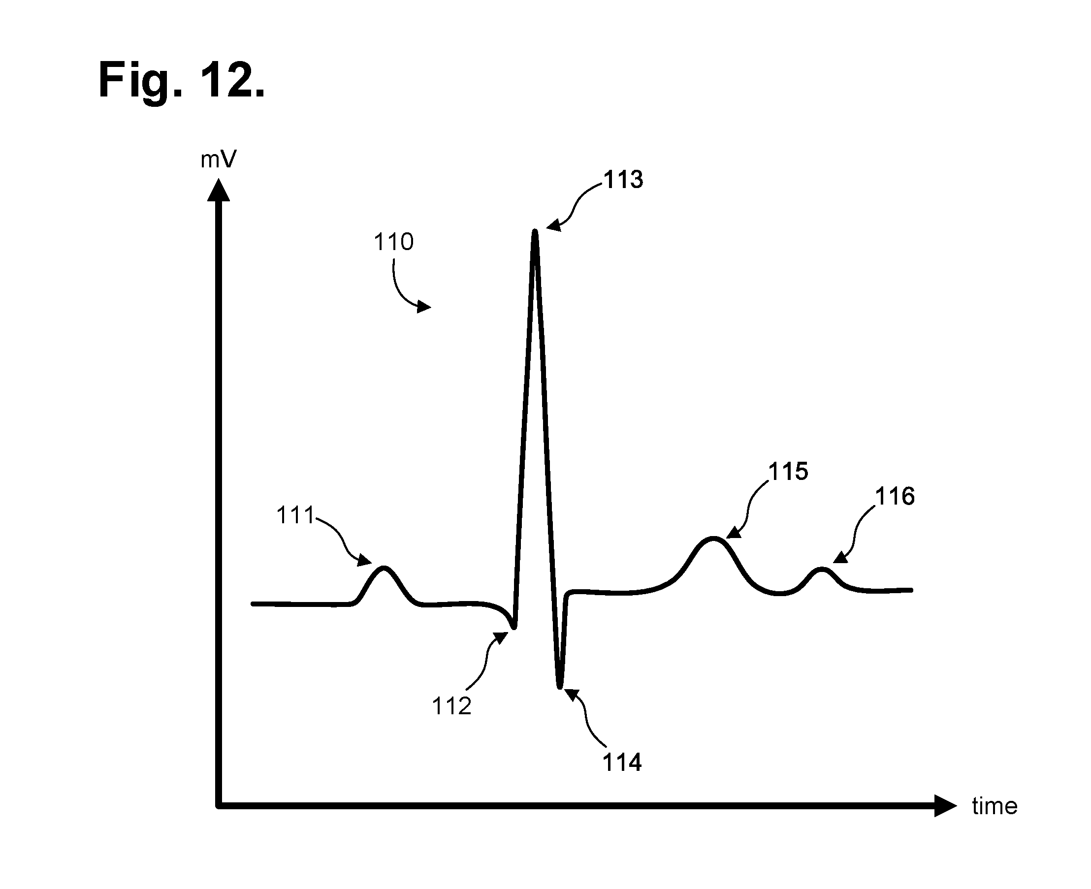
The heart emits electrical signals as a by-product of the propagation of the action potentials that trigger depolarization of heart fibers. An electrocardiogram (ECG) measures and records such electrical potentials to visually depict the electrical activity of the heart over time. Conventionally, a standardized set format 12-lead configuration is used by an ECG machine to record cardiac electrical signals from well-established traditional chest locations. Electrodes at the end of each lead are placed on the skin over the anterior thoracic region of the patient's body to the lower right and to the lower left of the sternum, on the left anterior chest, and on the limbs. Sensed cardiac electrical activity is represented by PQRSTU waveforms that can be interpreted post-ECG recordation to derive heart rate and physiology. The P-wave represents atrial electrical activity. The QRSTU components represent ventricular electrical activity.
An ECG is a tool used by physicians to diagnose heart problems and other potential health concerns. An ECG is a snapshot of heart function, typically recorded over 12 seconds, that can help diagnose rate and regularity of heartbeats, effect of drugs or cardiac devices, including pacemakers and implantable cardioverter-defibrillators (ICDs), and whether a patient has heart disease. ECGs are used in-clinic during appointments, and, as a result, are limited to recording only those heart-related aspects present at the time of recording. Sporadic conditions that may not show up during a spot ECG recording require other means to diagnose them. These disorders include fainting or syncope; rhythm disorders, such as tachyarrhythmias and bradyarrythmias; apneic episodes; and other cardiac and related disorders. Thus, an ECG only provides a partial picture and can be insufficient for complete patient diagnosis of many cardiac disorders.
Diagnostic efficacy can be improved, when appropriate, through the use of long-term extended ECG monitoring. Recording sufficient ECG and related physiology over an extended period is challenging, and often essential to enabling a physician to identify events of potential concern. A 30-day observation period is considered the "gold standard" of ECG monitoring, yet achieving a 30-day observation day period has proven unworkable because such ECG monitoring systems are arduous to employ, cumbersome to the patient, and excessively costly. Ambulatory monitoring in-clinic is implausible and impracticable. Nevertheless, if a patient's ECG could be recorded in an ambulatory setting, thereby allowing the patient to engage in activities of daily living, the chances of acquiring meaningful information and capturing an abnormal event while the patient is engaged in normal activities becomes more likely to be achieved.
For instance, the long-term wear of ECG electrodes is complicated by skin irritation and the inability ECG electrodes to maintain continual skin contact after a day or two. Moreover, time, dirt, moisture, and other environmental contaminants, as well as perspiration, skin oil, and dead skin cells from the patient's body, can get between an ECG electrode, the non-conductive adhesive used to adhere the ECG electrode, and the skin's surface. All of these factors adversely affect electrode adhesion and the quality of cardiac signal recordings. Furthermore, the physical movements of the patient and their clothing impart various compressional, tensile, and torsional forces on the contact point of an ECG electrode, especially over long recording times, and an inflexibly fastened ECG electrode will be prone to becoming dislodged. Notwithstanding the cause of electrode dislodgment, depending upon the type of ECG monitor employed, precise re-placement of a dislodged ECG electrode maybe essential to ensuring signal capture at the same fidelity. Moreover, dislodgment may occur unbeknownst to the patient, making the ECG recordings worthless. Further, some patients may have skin that is susceptible to itching or irritation, and the wearing of ECG electrodes can aggravate such skin conditions. Thus, a patient may want or need to periodically remove or replace ECG electrodes during a long-term ECG monitoring period, whether to replace a dislodged electrode, reestablish better adhesion, alleviate itching or irritation, allow for cleansing of the skin, allow for showering and exercise, or for other purpose. Such replacement or slight alteration in electrode location actually facilitates the goal of recording the ECG signal for long periods of time; however, ensuring that the level of quality of ECG recording and patient service remains constant over an extended period of time is dependent upon the monitoring equipment being up to a known standard. Use of third party consumables, such as ECG electrodes, could undermine expectations of ECG recording fidelity and adversely skew monitoring results.
Conventionally, Holter monitors are widely used for long-term extended ECG monitoring. Typically, they are used for only 24-48 hours. A typical Holter monitor is a wearable and portable version of an ECG that include cables for each electrode placed on the skin and a separate battery-powered ECG recorder. The cable and electrode combination (or leads) are placed in the anterior thoracic region in a manner similar to what is done with an in-clinic standard ECG machine. The duration of a Holter monitoring recording depends on the sensing and storage capabilities of the monitor, as well as battery life. A "looping" Holter monitor (or event) can operate for a longer period of time by overwriting older ECG tracings, thence "recycling" storage in favor of extended operation, yet at the risk of losing event data. Although capable of extended ECG monitoring, Holter monitors are cumbersome, expensive and typically only available by medical prescription, which limits their usability. Further, the skill required to properly place the electrodes on the patient's chest hinders or precludes a patient from replacing or removing the precordial leads and usually involves moving the patient from the physician office to a specialized center within the hospital or clinic.
The ZIO XT Patch and ZIO Event Card devices, manufactured by iRhythm Tech., Inc., San Francisco, Calif., are wearable stick-on monitoring devices that are typically worn on the upper left pectoral region to respectively provide continuous and looping ECG recording. The location is used to simulate surgically implanted monitors. Both of these devices are prescription-only and for single patient use. The ZIO XT Patch device is limited to a 14-day monitoring period, while the electrodes only of the ZIO Event Card device can be worn for up to 30 days. The ZIO XT Patch device combines both electronic recordation components, including battery, and physical electrodes into a unitary assembly that adheres to the patient's skin. The ZIO XT Patch device uses adhesive sufficiently strong to support the weight of both the monitor and the electrodes over an extended period of time and to resist disadherance from the patient's body, albeit at the cost of disallowing removal or relocation during the monitoring period. Moreover, throughout monitoring, the battery is continually depleted and battery capacity can potentially limit overall monitoring duration. The ZIO Event Card device is a form of downsized Holter monitor with a recorder component that must be removed temporarily during baths or other activities that could damage the non-waterproof electronics. Both devices represent compromises between length of wear and quality of ECG monitoring, especially with respect to ease of long term use, female-friendly fit, and quality of atrial (P-wave) signals. Moreover, both devices rely on the same set of ECG electrodes for the duration of the monitoring period; signal capture can suffer as the ECG electrodes disadhere from the patient's body over time.
Therefore, a need remains for an extended wear continuously recording ECG monitor practicably capable of being worn for a long period of time in both men and women and capable of recording atrial signals reliably with quality assurance implemented as part of disposable component replenishment.
A further need remains for a device capable of recording signals ideal for arrhythmia discrimination, especially a device designed for atrial activity recording.
SUMMARY
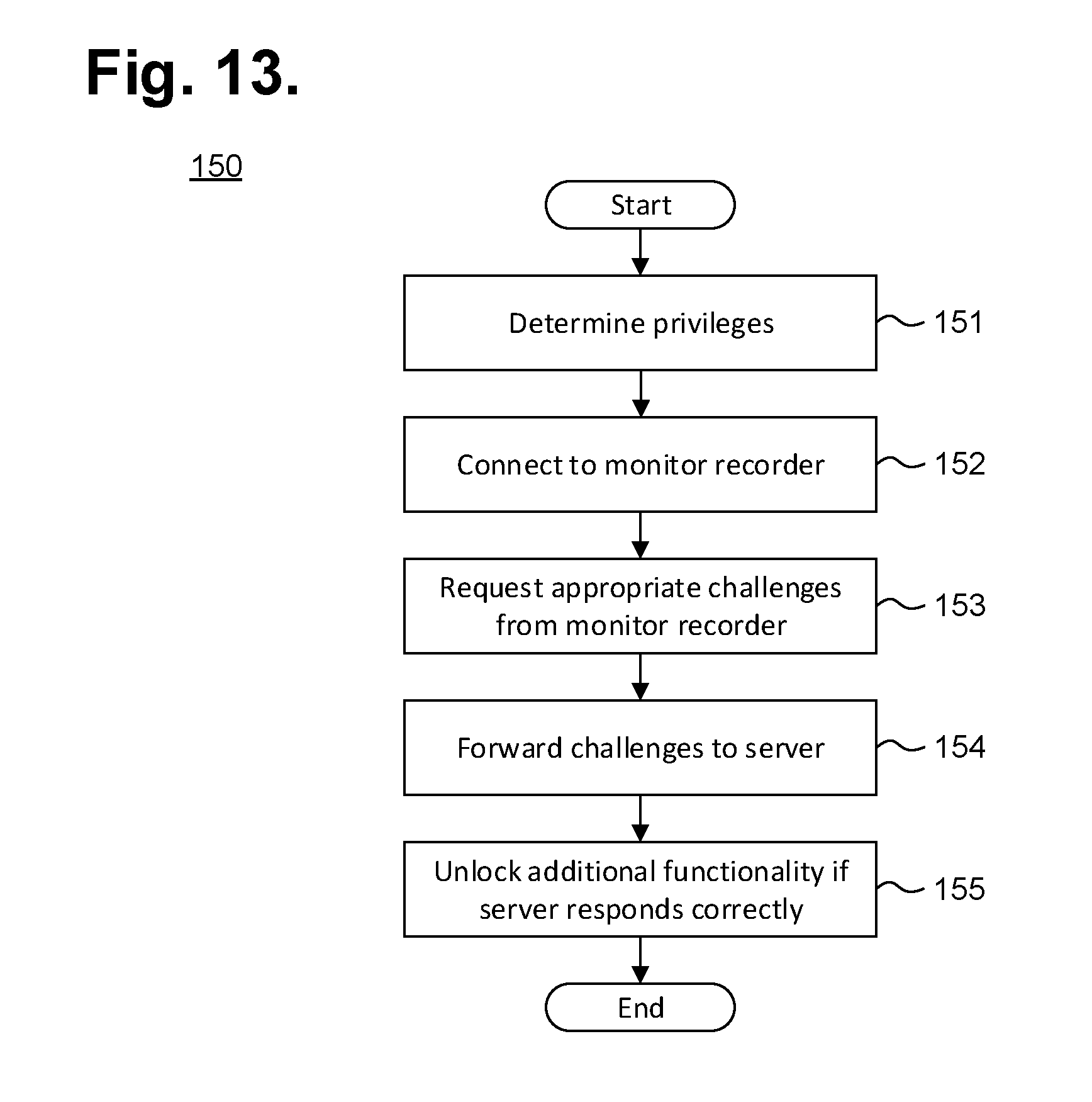
Physiological monitoring can be provided through a wearable monitor that includes two components, a flexible extended wear electrode patch and a removable reusable monitor recorder. The wearable monitor sits centrally (in the midline) on the patient's chest along the sternum oriented top-to-bottom. The placement of the wearable monitor in a location at the sternal midline (or immediately to either side of the sternum), with its unique narrow "hourglass"-like shape, benefits long-term extended wear by removing the requirement that ECG electrodes be continually placed in the same spots on the skin throughout the monitoring period. Instead, the patient is free to place an electrode patch anywhere within the general region of the sternum, the area most likely to record high quality atrial signals or P-waves. In addition, ensuring that the level of quality of ECG recording and patient service remains constant over an extended period of time is provided through self-authentication of electrode patches (and other accessories). The monitor recorder implements a challenge response scheme upon being connected to an electrode patch (or other accessory). Failing self-authentication, the monitor recorder signals an error condition. In addition, electrode patches (and other accessories) can be limited to operating for only a certain period of time, or with pre-defined operational parameters or privileges. In a further embodiment, a patient can purchase additional time, pre-defined operational parameters or privileges through a server-based subscription service.
One embodiment provides an extended wear electrocardiography and physiological sensor monitor recorder. A sealed housing is adapted to be removably secured into the non-conductive receptacle on a disposable extended wear electrode patch. Electronic circuitry is included within the sealed housing. An externally-powered micro-controller is operable to execute under micro programmable control only upon authentication of the disposable extended wear electrode patch during power up of the electronic circuitry. An electrocardiographic front end circuit is electrically interfaced to the micro-controller and is operable to sense electrocardiographic signals through electrocardiographic electrodes provided on the disposable extended wear electrode patch. Externally-powered flash memory is electrically interfaced with the micro-controller and is operable to store samples of the electrocardiographic signals.
A further embodiment provides an extended wear electrocardiography and physiological sensor monitor with self-authenticating electrocardiography monitoring circuit. An electrode patch includes an elongated strip of stretchable material and a pair of electrocardiographic electrodes conductively exposed on a contact surface of each end of the elongated strip. A non-conductive receptacle is adhered to an outward-facing surface of the elongated strip and has a plurality of electrical pads. A circuit is affixed on each end of the elongated strip and includes a pair of circuit traces electrically coupled to the pair of the electrocardiographic electrodes and a pair of the electrical pads. An electrocardiography monitor includes a sealed housing adapted to be removably secured into the non-conductive receptacle on the electrode patch. Electronic circuitry is included within the sealed housing and includes an electrocardiographic front end circuit operable to sense electrocardiographic signals through the electrocardiographic electrodes provided on the electrode patch and flash memory to record the electrocardiographic signals. A micro-controller periodically writes data into a memory of the electrode patch during continuous recording of the electrocardiographic signals via the front end circuit and determines an expiration of the electrode patch based on an amount of the data stored in the memory of the electrode patch.
The monitoring patch is especially suited to the female anatomy. The narrow longitudinal midsection can fit nicely within the intermammary cleft of the breasts without inducing discomfort, whereas conventional patch electrodes are wide and, if adhered between the breasts, would cause chafing, irritation, frustration, and annoyance, leading to low patient compliance.
The foregoing aspects enhance ECG monitoring performance and quality, facilitating long-term ECG recording, critical to accurate arrhythmia diagnosis.
In addition, the foregoing aspects enhance comfort in women (and certain men), but not irritation of the breasts, by placing the monitoring patch in the best location possible for optimizing the recording of cardiac signals from the atrium, another feature critical to proper arrhythmia diagnosis.
Finally, the foregoing aspects as relevant to monitoring are equally applicable to recording other physiological measures, such as temperature, respiratory rate, blood sugar, oxygen saturation, and blood pressure, as well as other measures of body chemistry and physiology.
Still other embodiments will become readily apparent to those skilled in the art from the following detailed description, wherein are described embodiments by way of illustrating the best mode contemplated. As will be realized, other and different embodiments are possible and the embodiments' several details are capable of modifications in various obvious respects, all without departing from their spirit and the scope. Accordingly, the drawings and detailed description are to be regarded as illustrative in nature and not as restrictive.
BRIEF DESCRIPTION OF THE DRAWINGS
FIGS. 1 and 2 are diagrams showing, by way of examples, an extended wear electrocardiography and physiological sensor monitor respectively fitted to the sternal region of a female patient and a male patient.
FIG. 3 is a functional block diagram showing a system for providing a self-authenticating electrocardiography monitoring circuit in accordance with one embodiment.
FIG. 4 is a perspective view showing an extended wear electrode patch with a monitor recorder in accordance with one embodiment inserted.
FIG. 5 is a perspective view showing the monitor recorder of FIG. 4.
FIG. 6 is a perspective view showing the extended wear electrode patch of FIG. 4 without a monitor recorder inserted.
FIG. 7 is a bottom plan view of the monitor recorder of FIG. 4.
FIG. 8 is a top view showing the flexible circuit of the extended wear electrode patch of FIG. 4 when mounted above the flexible backing.
FIG. 9 is a functional block diagram showing the component architecture of the circuitry of the monitor recorder of FIG. 4.
FIG. 10 is a functional block diagram showing the circuitry of the extended wear electrode patch of FIG. 4.
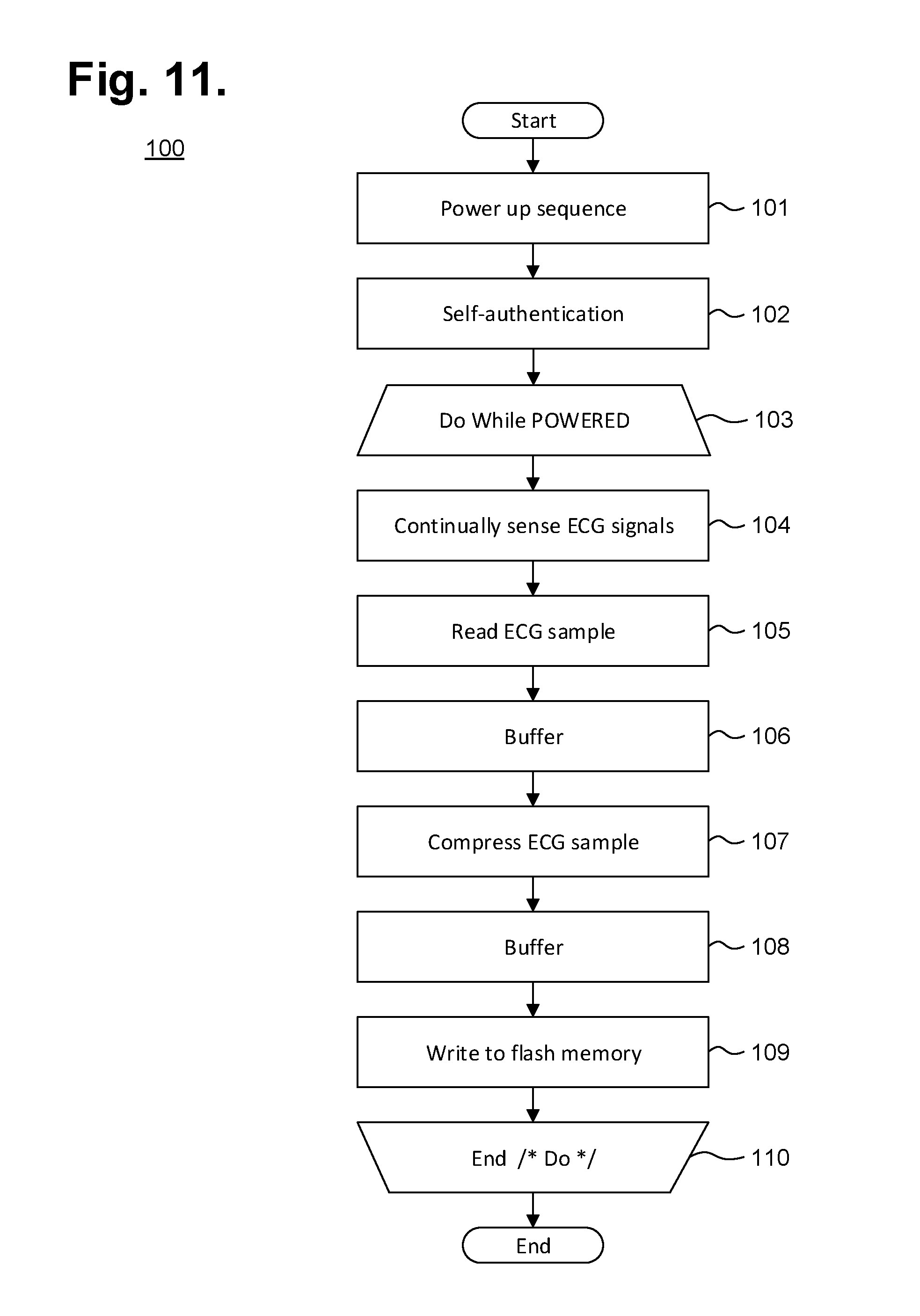
FIG. 11 is a flow diagram showing a monitor recorder-implemented method for monitoring ECG data for use in the monitor recorder of FIG. 4.
FIG. 12 is a graph showing, by way of example, a typical ECG waveform.
FIG. 13 is a flow diagram showing a method for providing a self-authenticating electrocardiography monitoring circuit in accordance with one embodiment.
DETAILED DESCRIPTION
Physiological monitoring can be provided through a wearable monitor that includes two components, a flexible extended wear electrode patch and a removable reusable monitor recorder. FIGS. 1 and 2 are diagrams showing, by way of examples, an extended wear electrocardiography and physiological sensor monitor 12, including a monitor recorder 14 in accordance with one embodiment, respectively fitted to the sternal region of a female patient 10 and a male patient 11. The wearable monitor 12 sits centrally (in the midline) on the patient's chest along the sternum 13 oriented top-to-bottom with the monitor recorder 14 preferably situated towards the patient's head. In a further embodiment, the orientation of the wearable monitor 12 can be corrected post-monitoring, as further described infra. The electrode patch 15 is shaped to fit comfortably and conformal to the contours of the patient's chest approximately centered on the sternal midline 16 (or immediately to either side of the sternum 13). The distal end of the electrode patch 15 extends towards the Xiphoid process and, depending upon the patient's build, may straddle the region over the Xiphoid process. The proximal end of the electrode patch 15, located under the monitor recorder 14, is below the manubrium and, depending upon patient's build, may straddle the region over the manubrium.
The placement of the wearable monitor 12 in a location at the sternal midline 16 (or immediately to either side of the sternum 13) significantly improves the ability of the wearable monitor 12 to cutaneously sense cardiac electric signals, particularly the P-wave (or atrial activity) and, to a lesser extent, the QRS interval signals in the ECG waveforms that indicate ventricular activity, while simultaneously facilitating comfortable long-term wear for many weeks. The sternum 13 overlies the right atrium of the heart and the placement of the wearable monitor 12 in the region of the sternal midline 13 puts the ECG electrodes of the electrode patch 15 in a location better adapted to sensing and recording P-wave signals than other placement locations, say, the upper left pectoral region or lateral thoracic region or the limb leads. In addition, placing the lower or inferior pole (ECG electrode) of the electrode patch 15 over (or near) the Xiphoid process facilitates sensing of ventricular activity and provides superior recordation of the QRS interval.
The monitor recorder 14 of the extended wear electrocardiography and physiological sensor monitor 12 senses and records the patient's ECG data into an onboard memory. Over time, disposable electrode patches 15 will require replacement and ensuring that the level of quality of ECG recording and patient service remains constant over an extended period of time is dependent upon the monitoring equipment, particularly the replacement electrode patches 15, being up to a known standard. FIG. 3 is a functional block diagram showing a system 120 for providing a self-authenticating electrocardiography monitoring circuit in accordance with one embodiment. Self-authentication allows quality and safety expectations to be maintained. The monitor recorder 14 is a reusable component that can be fitted during patient monitoring into a non-conductive receptacle provided on the electrode patch 15, as further described infra with reference to FIG. 4, and later removed for offloading of stored ECG data or to receive revised programming. The monitor recorder 14 executes an authentication protocol as part of a power up sequence, as further described infra with reference to FIG. 11. Following completion of ECG monitoring, the monitor recorder 14 can be connected to a download station 125, which could be a programmer or other device that permits the retrieval of stored ECG monitoring data, execution of diagnostics on or programming of the monitor recorder 14, or performance of other functions. The monitor recorder 14 has a set of electrical contacts (not shown) that enable the monitor recorder 14 to physically interface to a set of terminals 128 on a paired receptacle 127 of the download station 125. In turn, the download station 125 executes a communications or offload program 126 ("Offload") or similar program that interacts with the monitor recorder 14 via the physical interface to retrieve the stored ECG monitoring data. The download station 125 could be a server, personal computer, tablet or handheld computer, smart mobile device, or purpose-built programmer designed specific to the task of interfacing with a monitor recorder 14. Still other forms of download station 125 are possible.
Upon retrieving stored ECG monitoring data from a monitor recorder 14, middleware first operates on the retrieved data to adjust the ECG waveform, as necessary, and to convert the retrieved data into a format suitable for use by third party post-monitoring analysis software. The formatted data can then be retrieved from the download station 125 over a hard link 135 using a control program 137 ("Ctl") or analogous application executing on a personal computer 136 or other connectable computing device, via a communications link (not shown), whether wired or wireless, or by physical transfer of storage media (not shown). The personal computer 136 or other connectable device may also execute middleware that converts ECG data and other information into a format suitable for use by a third-party post-monitoring analysis program, as further described infra with reference to FIG. 13. Note that formatted data stored on the personal computer 136 would have to be maintained and safeguarded in the same manner as electronic medical records (EMRs) 134 in the secure database 124, as further discussed infra. In a further embodiment, the download station 125 is able to directly interface with other devices over a computer communications network 121, which could be some combination of a local area network and a wide area network, including the Internet, over a wired or wireless connection.
A client-server model could be used to employ a server 122 to remotely interface with the download station 125 over the network 121 and retrieve the formatted data or other information. The server 122 executes a patient management program 123 ("Mgt") or similar application that stores the retrieved formatted data and other information in a secure database 124 cataloged in that patient's EMRs 134. In addition, the patient management program 123 could manage a subscription service that authorizes a monitor recorder 14 to operate for a set period of time or under pre-defined operational parameters and privileges, such as described in infra with reference to FIG. 13.
The patient management program 123, or other trusted application, also maintains and safeguards the secure database 124 to limit access to patient EMRs 134 to only authorized parties for appropriate medical or other uses, such as mandated by state or federal law, such as under the Health Insurance Portability and Accountability Act (HIPAA) or per the European Union's Data Protection Directive. For example, a physician may seek to review and evaluate his patient's ECG monitoring data, as securely stored in the secure database 124. The physician would execute an application program 130 ("Pgm"), such as a post-monitoring ECG analysis program, on a personal computer 129 or other connectable computing device, and, through the application 130, coordinate access to his patient's EMRs 134 with the patient management program 123. Other schemes and safeguards to protect and maintain the integrity of patient EMRs 134 are possible.
During use, the electrode patch 15 is first adhered to the skin along the sternal midline 16 (or immediately to either side of the sternum 13). A monitor recorder 14 is then snapped into place on the electrode patch 15 to initiate ECG monitoring. FIG. 4 is a perspective view showing an extended wear electrode patch 15 with a monitor recorder 14 in accordance with one embodiment inserted. The body of the electrode patch 15 is preferably constructed using a flexible backing 20 formed as an elongated strip 21 of wrap knit or similar stretchable material with a narrow longitudinal mid-section 23 evenly tapering inward from both sides. A pair of cut-outs 22 between the distal and proximal ends of the electrode patch 15 create a narrow longitudinal midsection 23 or "isthmus" and defines an elongated "hourglass"-like shape, when viewed from above.
The electrode patch 15 incorporates features that significantly improve wearability, performance, and patient comfort throughout an extended monitoring period. During wear, the electrode patch 15 is susceptible to pushing, pulling, and torqueing movements, including compressional and torsional forces when the patient bends forward, and tensile and torsional forces when the patient leans backwards. To counter these stress forces, the electrode patch 15 incorporates strain and crimp reliefs, such as described in commonly-assigned U.S. Pat. No. 9,545,204, issued Jan. 17, 2017, the disclosure of which is incorporated by reference. In addition, the cut-outs 22 and longitudinal midsection 23 help minimize interference with and discomfort to breast tissue, particularly in women (and gynecomastic men). The cut-outs 22 and longitudinal midsection 23 further allow better conformity of the electrode patch 15 to sternal bowing and to the narrow isthmus of flat skin that can occur along the bottom of the intermammary cleft between the breasts, especially in buxom women. The cut-outs 22 and longitudinal midsection 23 help the electrode patch 15 fit nicely between a pair of female breasts in the intermammary cleft. Still other shapes, cut-outs and conformities to the electrode patch 15 are possible.
The monitor recorder 14 removably and reusably snaps into an electrically non-conductive receptacle 25 during use. The monitor recorder 14 contains electronic circuitry for recording and storing the patient's electrocardiography as sensed via a pair of ECG electrodes provided on the electrode patch 15, such as described in commonly-assigned U.S. Pat. No. 9,730,593, issued Aug. 15, 2017, the disclosure of which is incorporated by reference. The non-conductive receptacle 25 is provided on the top surface of the flexible backing 20 with a retention catch 26 and tension clip 27 molded into the non-conductive receptacle 25 to conformably receive and securely hold the monitor recorder 14 in place.
The monitor recorder 14 includes a sealed housing that snaps into place in the non-conductive receptacle 25. FIG. 5 is a perspective view showing the monitor recorder 14 of FIG. 4. The sealed housing 50 of the monitor recorder 14 intentionally has a rounded isosceles trapezoidal-like shape 52, when viewed from above, such as described in commonly-assigned U.S. Design Patent No. D717955, issued Nov. 18, 2014, the disclosure of which is incorporated by reference. The edges 51 along the top and bottom surfaces are rounded for patient comfort. The sealed housing 50 is approximately 47 mm long, 23 mm wide at the widest point, and 7 mm high, excluding a patient-operable tactile-feedback button 55. The sealed housing 50 can be molded out of polycarbonate, ABS, or an alloy of those two materials. The button 55 is waterproof and the button's top outer surface is molded silicon rubber or similar soft pliable material. A retention detent 53 and tension detent 54 are molded along the edges of the top surface of the housing 50 to respectively engage the retention catch 26 and the tension clip 27 molded into non-conductive receptacle 25. Other shapes, features, and conformities of the sealed housing 50 are possible.
The electrode patch 15 is intended to be disposable. The monitor recorder 14, however, is reusable and can be transferred to successive electrode patches 15 to ensure continuity of monitoring. The placement of the wearable monitor 12 in a location at the sternal midline 16 (or immediately to either side of the sternum 13) benefits long-term extended wear by removing the requirement that ECG electrodes be continually placed in the same spots on the skin throughout the monitoring period. Instead, the patient is free to place an electrode patch 15 anywhere within the general region of the sternum 13.
As a result, at any point during ECG monitoring, the patient's skin is able to recover from the wearing of an electrode patch 15, which increases patient comfort and satisfaction, while the monitor recorder 14 ensures ECG monitoring continuity with minimal effort. A monitor recorder 14 is merely unsnapped from a worn out electrode patch 15, the worn out electrode patch 15 is removed from the skin, a new electrode patch 15 is adhered to the skin, possibly in a new spot immediately adjacent to the earlier location, and the same monitor recorder 14 is snapped into the new electrode patch 15 to reinitiate and continue the ECG monitoring.
During use, the electrode patch 15 is first adhered to the skin in the sternal region. FIG. 6 is a perspective view showing the extended wear electrode patch 15 of FIG. 4 without a monitor recorder 14 inserted. A flexible circuit 32 is adhered to each end of the flexible backing 20. A distal circuit trace 33 and a proximal circuit trace (not shown) electrically couple ECG electrodes (not shown) to a pair of electrical pads 34. The electrical pads 34 are provided within a moisture-resistant seal 35 formed on the bottom surface of the non-conductive receptacle 25. When the monitor recorder 14 is securely received into the non-conductive receptacle 25, that is, snapped into place, the electrical pads 34 interface to electrical contacts (not shown) protruding from the bottom surface of the monitor recorder 14, and the moisture-resistant seal 35 enables the monitor recorder 14 to be worn at all times, even during bathing or other activities that could expose the monitor recorder 14 to moisture.
In addition, a battery compartment 36 is formed on the bottom surface of the non-conductive receptacle 25, and a pair of battery leads (not shown) electrically interface the battery to another pair of the electrical pads 34. The battery contained within the battery compartment 35 can be replaceable, rechargeable or disposable.
The monitor recorder 14 draws power externally from the battery provided in the non-conductive receptacle 25, thereby uniquely obviating the need for the monitor recorder 14 to carry a dedicated power source. FIG. 7 is a bottom plan view of the monitor recorder 14 of FIG. 4. A cavity 58 is formed on the bottom surface of the sealed housing 50 to accommodate the upward projection of the battery compartment 36 from the bottom surface of the non-conductive receptacle 25, when the monitor recorder 14 is secured in place on the non-conductive receptacle 25. A set of electrical contacts 56 protrude from the bottom surface of the sealed housing 50 and are arranged in alignment with the electrical pads 34 provided on the bottom surface of the non-conductive receptacle 25 to establish electrical connections between the electrode patch 15 and the monitor recorder 14. In addition, a seal coupling 57 circumferentially surrounds the set of electrical contacts 56 and securely mates with the moisture-resistant seal 35 formed on the bottom surface of the non-conductive receptacle 25.
The placement of the flexible backing 20 on the sternal midline 16 (or immediately to either side of the sternum 13) also helps to minimize the side-to-side movement of the wearable monitor 12 in the left- and right-handed directions during wear. To counter the dislodgment of the flexible backing 20 due to compressional and torsional forces, a layer of non-irritating adhesive, such as hydrocolloid, is provided at least partially on the underside, or contact, surface of the flexible backing 20, but only on the distal end 30 and the proximal end 31. As a result, the underside, or contact surface of the longitudinal midsection 23 does not have an adhesive layer and remains free to move relative to the skin. Thus, the longitudinal midsection 23 forms a crimp relief that respectively facilitates compression and twisting of the flexible backing 20 in response to compressional and torsional forces. Other forms of flexible backing crimp reliefs are possible.
Unlike the flexible backing 20, the flexible circuit 32 is only able to bend and cannot stretch in a planar direction. The flexible circuit 32 can be provided either above or below the flexible backing 20. FIG. 8 is a top view showing the flexible circuit 32 of the extended wear electrode patch 15 of FIG. 4 when mounted above the flexible backing 20. A distal ECG electrode 38 and proximal ECG electrode 39 are respectively coupled to the distal and proximal ends of the flexible circuit 32. A strain relief 40 is defined in the flexible circuit 32 at a location that is partially underneath the battery compartment 36 when the flexible circuit 32 is affixed to the flexible backing 20. The strain relief 40 is laterally extendable to counter dislodgment of the ECG electrodes 38, 39 due to tensile and torsional forces. A pair of strain relief cutouts 41 partially extend transversely from each opposite side of the flexible circuit 32 and continue longitudinally towards each other to define in `S`-shaped pattern, when viewed from above. The strain relief respectively facilitates longitudinal extension and twisting of the flexible circuit 32 in response to tensile and torsional forces. Other forms of circuit board strain relief are possible.
ECG monitoring and other functions performed by the monitor recorder 14 are provided through a micro controlled architecture. FIG. 9 is a functional block diagram showing the component architecture of the circuitry 60 of the monitor recorder 14 of FIG. 4. The circuitry 60 is externally powered through a battery provided in the non-conductive receptacle 25 (shown in FIG. 6). Both power and raw ECG signals, which originate in the pair of ECG electrodes 38, 39 (shown in FIG. 8) on the distal and proximal ends of the electrode patch 15, are received through an external connector 65 that mates with a corresponding physical connector on the electrode patch 15. The external connector 65 includes the set of electrical contacts 56 that protrude from the bottom surface of the sealed housing 50 and which physically and electrically interface with the set of pads 34 provided on the bottom surface of the non-conductive receptacle 25. The external connector includes electrical contacts 56 for data download, microcontroller communications, power, analog inputs, and a peripheral expansion port. The arrangement of the pins on the electrical connector 65 of the monitor recorder 14 and the device into which the monitor recorder 14 is attached, whether an electrode patch 15 or download station (not shown), follow the same electrical pin assignment convention to facilitate interoperability. The external connector 65 also serves as a physical interface to a download station that permits the retrieval of stored ECG monitoring data, communication with the monitor recorder 14, and performance of other functions.
Operation of the circuitry 60 of the monitor recorder 14 is managed by a microcontroller 61. The micro-controller 61 includes a program memory unit containing internal flash memory that is readable and writeable. The internal flash memory can also be programmed externally. The micro-controller 61 draws power externally from the battery provided on the electrode patch 15 via a pair of the electrical contacts 56. The microcontroller 61 connects to the ECG front end circuit 63 that measures raw cutaneous electrical signals and generates an analog ECG signal representative of the electrical activity of the patient's heart over time.
The circuitry 60 of the monitor recorder 14 also includes a flash memory 62, which the micro-controller 61 uses for storing ECG monitoring data and other physiology and information. The flash memory 62 also draws power externally from the battery provided on the electrode patch 15 via a pair of the electrical contacts 56. Data is stored in a serial flash memory circuit, which supports read, erase and program operations over a communications bus. The flash memory 62 enables the microcontroller 61 to store digitized ECG data. The communications bus further enables the flash memory 62 to be directly accessed externally over the external connector 65 when the monitor recorder 14 is interfaced to a download station.
The circuitry 60 of the monitor recorder 14 further includes an actigraphy sensor 64 implemented as a 3-axis accelerometer. The accelerometer may be configured to generate interrupt signals to the microcontroller 61 by independent initial wake up and free fall events, as well as by device position. In addition, the actigraphy provided by the accelerometer can be used during post-monitoring analysis to correct the orientation of the monitor recorder 14 if, for instance, the monitor recorder 14 has been inadvertently installed upside down, that is, with the monitor recorder 14 oriented on the electrode patch 15 towards the patient's feet, as well as for other event occurrence analyses, such as described in commonly-assigned, U.S. Pat. No. 9,737,224, issued Aug. 22, 2017, the disclosure of which is incorporated by reference.
The microcontroller 61 includes an expansion port that also utilizes the communications bus. External devices, separately drawing power externally from the battery provided on the electrode patch 15 or other source, can interface to the microcontroller 61 over the expansion port in half duplex mode. For instance, an external physiology sensor can be provided as part of the circuitry 60 of the monitor recorder 14, or can be provided on the electrode patch 15 with communication with the micro-controller 61 provided over one of the electrical contacts 56. The physiology sensor can include a SpO.sub.2 sensor, blood pressure sensor, temperature sensor, respiratory rate sensor, glucose sensor, airflow sensor, volumetric pressure sensing, or other types of sensor or telemetric input sources. For instance, the integration of an airflow sensor is described in commonly-assigned U.S. Pat. No. 9,364,155, issued Jun. 14, 2016, the disclosure which is incorporated by reference. In a further embodiment, a wireless interface for interfacing with other wearable (or implantable) physiology monitors, as well as data offload and programming, can be provided as part of the circuitry 60 of the monitor recorder 14, or can be provided on the electrode patch 15 with communication with the micro-controller 61 provided over one of the electrical contacts 56, such as described in commonly-assigned U.S. Pat. No. 9,433,367, issued Sep. 6, 2016 the disclosure of which is incorporated by reference.
Finally, the circuitry 60 of the monitor recorder 14 includes patient-interfaceable components, including a tactile feedback button 66, which a patient can press to mark events or to perform other functions, and a buzzer 67, such as a speaker, magnetic resonator or piezoelectric buzzer. The buzzer 67 can be used by the microcontroller 61 to output feedback to a patient such as to confirm power up and initiation of ECG monitoring. Still other components as part of the circuitry 60 of the monitor recorder 14 are possible.
While the monitor recorder 14 operates under micro control, most of the electrical components of the electrode patch 15 operate passively. FIG. 10 is a functional block diagram showing the circuitry 70 of the extended wear electrode patch 15 of FIG. 4. The circuitry 70 of the electrode patch 15 is electrically coupled with the circuitry 60 of the monitor recorder 14 through an external connector 74. The external connector 74 is terminated through the set of pads 34 provided on the bottom of the non-conductive receptacle 25, which electrically mate to corresponding electrical contacts 56 protruding from the bottom surface of the sealed housing 50 to electrically interface the monitor recorder 14 to the electrode patch 15.
The circuitry 70 of the electrode patch 15 performs three primary functions. First, a battery 71 is provided in a battery compartment formed on the bottom surface of the non-conductive receptacle 25. The battery 71 is electrically interfaced to the circuitry 60 of the monitor recorder 14 as a source of external power. The unique provisioning of the battery 71 on the electrode patch 15 provides several advantages. First, the locating of the battery 71 physically on the electrode patch 15 lowers the center of gravity of the overall wearable monitor 12 and thereby helps to minimize shear forces and the effects of movements of the patient and clothing. Moreover, the housing 50 of the monitor recorder 14 is sealed against moisture and providing power externally avoids having to either periodically open the housing 50 for the battery replacement, which also creates the potential for moisture intrusion and human error, or to recharge the battery, which can potentially take the monitor recorder 14 off line for hours at a time. In addition, the electrode patch 15 is intended to be disposable, while the monitor recorder 14 is a reusable component. Each time that the electrode patch 15 is replaced, a fresh battery is provided for the use of the monitor recorder 14, which enhances ECG monitoring performance quality and duration of use. Finally, the architecture of the monitor recorder 14 is open, in that other physiology sensors or components can be added by virtue of the expansion port of the microcontroller 61. Requiring those additional sensors or components to draw power from a source external to the monitor recorder 14 keeps power considerations independent of the monitor recorder 14. Thus, a battery of higher capacity could be introduced when needed to support the additional sensors or components without effecting the monitor recorders circuitry 60.
Second, the pair of ECG electrodes 38, 39 respectively provided on the distal and proximal ends of the flexible circuit 32 are electrically coupled to the set of pads 34 provided on the bottom of the non-conductive receptacle 25 by way of their respective circuit traces 33, 37. The signal ECG electrode 39 includes a protection circuit 72, which is an inline resistor that protects the patient from excessive leakage current.
Last, in a further embodiment, the circuitry 70 of the electrode patch 15 includes a cryptographic circuit 73 to authenticate an electrode patch 15 for use with a monitor recorder 14. The cryptographic circuit 73 includes a device capable of secure authentication and validation. The cryptographic device 73 ensures that only genuine, non-expired, safe, and authenticated electrode patches 15 are permitted to provide monitoring data to a monitor recorder 14.
The monitor recorder 14 continuously monitors the patient's heart rate and physiology. FIG. 11 is a flow diagram showing a monitor recorder-implemented method 100 for monitoring ECG data for use in the monitor recorder 14 of FIG. 4. Initially, upon being connected to the set of pads 34 provided with the non-conductive receptacle 25 when the monitor recorder 14 is snapped into place, the microcontroller 61 executes a power up sequence (step 101) and performs self-authentication of the electrode patch 15 (step 102). During the power up sequence, the voltage of the battery 71 is checked, the state of the flash memory 62 is confirmed, both in terms of operability check and available capacity, and microcontroller operation is diagnostically confirmed.
Self-authentication is performed between the microcontroller 61 and the electrode patch 15 each time that the monitor recorder 14 is inserted into an electrode patch 15 (or other accessory) to ensure patient safety. An authenticated patch will conform to product quality standards, as well as applicable federal regulatory quality requirements and international standards, such as ISO 13485, IEC 60601-2-47 and IEC 60601-1. Quality assurance, through self-authentication, is crucial, as electrode patches 15 and other accessories may be authorized, but may not necessarily be manufactured, by the entity ultimately responsible for quality standards compliance. Self-authentication mitigates the risk of incorrect device output due to non-compliant accessories.
In one embodiment, the micro-controller 61 contains a private key or a precomputed digest, of which the electrode patch 15 (or other accessory) will have a copy. To authenticate an electrode patch 15 (or other accessory), the micro-controller 61 will challenge the electrode patch 15 (or other accessory) using a code hashed with the private key or precomputed digest. If the electrode patch 15 (or other accessory) responds correctly, the micro-controller 61 will continue with normal program execution. Otherwise, the monitor recorder 14 will signal an error condition, such as chirping the buzzer 67 to notify the patient. Failing self-authentication, other actions could also be taken.
In a further embodiment, an electrode patch 15 (or other accessory) can be set to operate for only a certain period of time. Upon authentication, the monitor recorder 14 will run with that electrode patch 15 (or other accessory) until the electrode patch 15 (or other accessory) is depleted. If the electrode patch 15 (or other accessory) is detected to be expired during self-authentication, the monitor recorder 14 will fail to operate or signal an error condition. To cause an electrode patch 15 (or other accessory) to expire after a certain amount of time has elapsed, the micro-controller 61 periodically writes into the read-only memory (ROM) of the cryptographic circuit 73. After the data in the ROM written by the micro-controller 61 has reached a certain fullness, the micro-controller 61 will turn off to ensure that an expired electrode patch 15 (or other accessory) does not create an unsafe condition, such as an incorrect output. Still other forms of authentication and device expiration are possible.
Following satisfactory completion of the power up sequence, an iterative processing loop (steps 103-110) is continually executed by the microcontroller 61. During each iteration (step 103) of the processing loop, the ECG frontend 63 (shown in FIG. 9) continually senses the cutaneous ECG electrical signals (step 104) via the ECG electrodes 38, 29 and is optimized to maintain the integrity of the P-wave. A sample of the ECG signal is read (step 105) by the microcontroller 61 by sampling the analog ECG signal output front end 63. FIG. 12 is a graph showing, by way of example, a typical ECG waveform 110. The x-axis represents time in approximate units of tenths of a second. The y-axis represents cutaneous electrical signal strength in approximate units of millivolts. The P-wave 111 has a smooth, normally upward, that is, positive, waveform that indicates atrial depolarization. The QRS complex usually begins with the downward deflection of a Q wave 112, followed by a larger upward deflection of an R-wave 113, and terminated with a downward waveform of the S wave 114, collectively representative of ventricular depolarization. The T wave 115 is normally a modest upward waveform, representative of ventricular depolarization, while the U wave 116, often not directly observable, indicates the recovery period of the Purkinje conduction fibers.
Sampling of the R-to-R interval enables heart rate information derivation. For instance, the R-to-R interval represents the ventricular rate and rhythm, while the P-to-P interval represents the atrial rate and rhythm. Importantly, the PR interval is indicative of atrioventricular (AV) conduction time and abnormalities in the PR interval can reveal underlying heart disorders, thus representing another reason why the P-wave quality achievable by the extended wear ambulatory electrocardiography and physiological sensor monitor described herein is medically unique and important. The long-term observation of these ECG indicia, as provided through extended wear of the wearable monitor 12, provides valuable insights to the patient's cardiac function and overall well-being.
Each sampled ECG signal, in quantized and digitized form, is temporarily staged in buffer (step 106), pending compression preparatory to storage in the flash memory 62 (step 107). Following compression, the compressed ECG digitized sample is again buffered (step 108), then written to the flash memory 62 (step 109) using the communications bus. Processing continues (step 110), so long as the monitoring recorder 14 remains connected to the electrode patch 15 (and storage space remains available in the flash memory 62), after which the processing loop is exited and execution terminates. Still other operations and steps are possible.
The patient management program 123 could manage a subscription service that authorizes a monitor recorder 14 to operate for a set period of time or under pre-defined operational parameters and privileges. FIG. 13 is a flow diagram showing a method 150 for providing a self-authenticating electrocardiography monitoring circuit in accordance with one embodiment. The method 150 can be implemented in software and execution of the software can be performed on a download station 125, which could be a programmer or other device, or a computer system, including a server 122 or personal computer 129, such as further described supra with reference to FIG. 3, as a series of process or method modules or steps.
For convenience, the method 150 will be described in the context of being performed by a personal computer 136 or other connectable computing device (shown in FIG. 3) as middleware that converts ECG data and other information into a format suitable for use by a third-party post-monitoring analysis program. Execution of the method 150 by a computer system would be analogous mutatis mutandis.
Initially, the download station 125 is connected to the monitor recorder 14 (step 151), such as by physically interfacing to a set of terminals 128 on a paired receptacle 127 or by wireless connection, if available. The data stored on the monitor recorder 14, including ECG and physiological monitoring data, other recorded data, and other information are retrieved (step 152) over a hard link 135 using a control program 137 ("Ctl") or analogous application executing on a personal computer 136 or other connectable computing device.
The data retrieved from the monitor recorder 14 is in a proprietary storage format and each datum of recorded ECG monitoring data, as well as any other physiological data or other information, must be converted, so that the data can be used by a third-party post-monitoring analysis program. Each datum of ECG monitoring data is converted by the middleware (steps 153-159) in an iterative processing loop. During each iteration (step 153), the ECG datum is read (step 154) and, if necessary, the gain of the ECG signal is adjusted (step 155) to compensate, for instance, for relocation or replacement of the electrode patch 15 during the monitoring period.
In addition, depending upon the configuration of the wearable monitor 12, other physiological data (or other information), including patient events, such as a fall, peak activity level, detection of patient activity levels and states, sedentary detection and so on, may be recorded along with the ECG monitoring data. For instance, actigraphy data may have been sampled by the actigraphy sensor 64 based on a sensed event occurrence, such as a sudden change in orientation due to the patient taking a fall. In response, the monitor recorder 14 will embed the actigraphy data samples into the stream of data, including ECG monitoring data that is recorded to the flash memory 62 by the micro-controller 61. Post-monitoring, the actigraphy data is temporally matched to the ECG data to provide the proper physiological context to the sensed event occurrence. As a result, the three-axis actigraphy signal is turned into an actionable event occurrence that is provided, through conversion by the middleware, to third party post-monitoring analysis programs, along with the ECG recordings contemporaneous to the event occurrence. Other types of processing of the other physiological data (or other information) are possible.
Thus, during execution of the middleware, any other physiological data (or other information) that has been embedded into the recorded ECG monitoring data is read (step 156) and time-correlated to the time frame of the ECG signals that occurred at the time that the other physiological data (or other information) was noted (step 157). Finally, the ECG datum, signal gain adjusted, if appropriate, and other physiological data, if applicable and as time-correlated, are stored in a format suitable to the backend software (step 158) used in post-monitoring analysis.
While the invention has been particularly shown and described as referenced to the embodiments thereof, those skilled in the art will understand that the foregoing and other changes in form and detail may be made therein without departing from the spirit and scope.
* * * * *
References
-
thehottestgadgets.com/2008/09/the-15-hottest-wearable-gadgets-001253
-
businesswire.com/news/home/20121203005545/en/AliveCor%E2%80%99s-Heart-Monitor-iPhone-Receives-FDA-Clearance#.U7rtq7FVTyF
-
fitbit.com
-
businessinsider.com/fitbit-flex-vs-jawbone-up-2013-5?op=1
-
nike.com/us/en_us/c/nikeplus-fuelband
-
dcrainmaker.com/2013/09/polar-loop-firstlook.html
-
clevemed.com/sleepview/overview.shtml
-
somnomedics.eu/news-events/publications/somnowatchtm.html
-
irhythmtech.com/zio-solution/zio-event
-
-
endurancesportswire.com/omegawave-launches-consumer-app-2-0-in-u-s
-
decibel.ni.com/content/docs/Doc-26652
-
ehrlich.tv/KARDiVAR-Software.pdf
-
biopac.com/research.asp?CatID=37&Main=Software
-
drkucera.eu/upload_doc/hrv_analysis
D00000
D00001
D00002
D00003
D00004
D00005
D00006
D00007
D00008
XML
uspto.report is an independent third-party trademark research tool that is not affiliated, endorsed, or sponsored by the United States Patent and Trademark Office (USPTO) or any other governmental organization. The information provided by uspto.report is based on publicly available data at the time of writing and is intended for informational purposes only.
While we strive to provide accurate and up-to-date information, we do not guarantee the accuracy, completeness, reliability, or suitability of the information displayed on this site. The use of this site is at your own risk. Any reliance you place on such information is therefore strictly at your own risk.
All official trademark data, including owner information, should be verified by visiting the official USPTO website at www.uspto.gov. This site is not intended to replace professional legal advice and should not be used as a substitute for consulting with a legal professional who is knowledgeable about trademark law.