Sealed structural body and method for manufacturing the same
Kodama , et al. A
U.S. patent number 10,392,296 [Application Number 15/033,167] was granted by the patent office on 2019-08-27 for sealed structural body and method for manufacturing the same. This patent grant is currently assigned to HITACHI, LTD.. The grantee listed for this patent is HITACHI, LTD.. Invention is credited to Takuya Aoyagi, Motomune Kodama, Masanori Miyagi, Takashi Naito.


| United States Patent | 10,392,296 |
| Kodama , et al. | August 27, 2019 |
Sealed structural body and method for manufacturing the same
Abstract
A sealed structural body has an internal space and is made of glass, wherein at least a part of a boundary between the internal space of the sealed structural body and the outside is separated by a sealing material containing a metal material and a lead-free oxide glass. The lead-free oxide glass contains at least one of element Ag or P, Te, and V.
| Inventors: | Kodama; Motomune (Tokyo, JP), Miyagi; Masanori (Tokyo, JP), Aoyagi; Takuya (Tokyo, JP), Naito; Takashi (Tokyo, JP) | ||||||||||
|---|---|---|---|---|---|---|---|---|---|---|---|
| Applicant: |
|
||||||||||
| Assignee: | HITACHI, LTD. (Tokyo,
JP) |
||||||||||
| Family ID: | 53273044 | ||||||||||
| Appl. No.: | 15/033,167 | ||||||||||
| Filed: | December 4, 2013 | ||||||||||
| PCT Filed: | December 04, 2013 | ||||||||||
| PCT No.: | PCT/JP2013/082526 | ||||||||||
| 371(c)(1),(2),(4) Date: | April 29, 2016 | ||||||||||
| PCT Pub. No.: | WO2015/083248 | ||||||||||
| PCT Pub. Date: | June 11, 2015 |
Prior Publication Data
| Document Identifier | Publication Date | |
|---|---|---|
| US 20160257610 A1 | Sep 8, 2016 | |
| Current U.S. Class: | 1/1 |
| Current CPC Class: | B32B 37/14 (20130101); C03C 8/08 (20130101); B32B 7/14 (20130101); C03C 8/18 (20130101); C03C 8/02 (20130101); C03C 3/122 (20130101); C03C 17/008 (20130101); C03C 17/003 (20130101); C03C 8/24 (20130101); C03C 27/06 (20130101); C03C 3/21 (20130101); B32B 38/0008 (20130101); C03C 17/04 (20130101); B32B 17/06 (20130101); B32B 1/02 (20130101); C03C 17/007 (20130101); B32B 2457/00 (20130101); E06B 3/66 (20130101); C03C 2218/32 (20130101); B32B 2307/412 (20130101); B32B 2250/02 (20130101); B32B 2439/40 (20130101); Y02B 80/22 (20130101); B32B 2419/00 (20130101); B32B 2605/00 (20130101); C03C 2217/23 (20130101); B32B 2255/20 (20130101); E06B 3/66357 (20130101); E06B 3/6612 (20130101); C03C 2217/218 (20130101); B32B 2307/304 (20130101) |
| Current International Class: | B32B 17/06 (20060101); C03C 8/08 (20060101); C03C 3/12 (20060101); C03C 3/21 (20060101); C03C 8/24 (20060101); B32B 1/02 (20060101); B32B 7/14 (20060101); C03C 17/04 (20060101); E06B 3/66 (20060101); B32B 37/14 (20060101); C03C 27/06 (20060101); C03C 8/18 (20060101); B32B 38/00 (20060101); C03C 17/00 (20060101); C03C 8/02 (20060101); E06B 3/663 (20060101) |
References Cited [Referenced By]
U.S. Patent Documents
| 3798114 | March 1974 | Chvatal |
| 6344424 | February 2002 | Goto et al. |
| 8075961 | December 2011 | Sawai |
| 2008/0164462 | July 2008 | Lee et al. |
| 2009/0136766 | May 2009 | Son et al. |
| 2009/0199897 | August 2009 | Naito et al. |
| 2010/0180934 | July 2010 | Naito et al. |
| 2010/0331165 | December 2010 | Lee et al. |
| 2012/0213951 | August 2012 | Dennis |
| 2014/0145122 | May 2014 | Sawai et al. |
| 2015/0008573 | January 2015 | Sawai et al. |
| 2015/0068665 | March 2015 | Abe et al. |
| 101009318 | Aug 2007 | CN | |||
| 101503277 | Aug 2009 | CN | |||
| 2000-327363 | Nov 2000 | JP | |||
| 2006-342044 | Dec 2006 | JP | |||
| 2008171811 | Jul 2008 | JP | |||
| 2009126782 | Jun 2009 | JP | |||
| 2009-209032 | Sep 2009 | JP | |||
| 2010-184852 | Aug 2010 | JP | |||
| 2011011925 | Jan 2011 | JP | |||
| 2011057477 | Mar 2011 | JP | |||
| 2011126722 | Jun 2011 | JP | |||
| 2013-032255 | Feb 2013 | JP | |||
| 2013-136470 | Jul 2013 | JP | |||
| 9310052 | May 1993 | WO | |||
| 2013005600 | Jan 2013 | WO | |||
| 2013111434 | Aug 2013 | WO | |||
| 2013/172034 | Nov 2013 | WO | |||
Other References
|
Machine translation of applicant cited reference CN 101009318. cited by examiner . European Search Report for European Patent Appln. No. 13898801.9 dated Jun. 28, 2017. cited by applicant . The Chinese Office Action dated Jul. 31, 2017 for the Chinese Application No. 201380080467.5. cited by applicant . Japanese Office Action for Japanese Patent Application No. 2015-551326 dated May 30, 2017. cited by applicant. |
Primary Examiner: Loney; Donald J
Attorney, Agent or Firm: Volpe and Koenig, P.C.
Claims
The invention claimed is:
1. A sealed structural body including an internal space and made of glass, wherein: at least a part of a boundary between the internal space of the sealed structural body and an outside is separated by a sealing material containing a metal material and a lead-free oxide glass, the lead-free oxide glass containing Te, V, and at least one of element Ag or P, the metal material has a lower melting point than a softening point at which the lead-free oxide glass begins to flow, the metal material has a crystalline structure, the lead-free oxide glass has a non-crystalline structure, the metal material maintains an original particle shape, a particle diameter of the metal material is 0.5 to 1 times the thickness of the internal space, and the internal space has a thickness of 70 .mu.m or greater.
2. The sealed structural body according to claim 1, wherein the lead-free oxide glass comprises 17 to 45 mass % of V2O5, 25 to 40 mass % of TeO2, and 20 to 45 mass % of Ag2O in oxide equivalents.
3. The sealed structural body according to claim 1, wherein the lead-free oxide glass comprises 85 mass % or greater of V2O5+TeO2+Ag2O in oxide equivalents.
4. The sealed structural body according to claim 1, wherein the lead-free oxide glass comprises 17 to 50 mass % of V2O5, 20 to 33 mass % of TeO2, and 4.8 to 12 mass % of P2O5 in oxide equivalents.
5. The sealed structural body according to claim 1, wherein the metal material includes at least one of Ag, Cu, Al, Sn, Zn, Au, In, Bi, or Pt.
6. The sealed structural body according to claim 1, wherein the metal material has the melting point lower than the softening point of the lead-free oxide glass.
7. The sealed structural body according to claim 1, wherein the sealed structural body includes two glass plates with outer periphery portions thereof bonded by the sealing material so as to form the internal space.
8. The sealed structural body according to claim 7, wherein the metal material has an average particle diameter of 0.5 to 1 times the interval of the internal space.
9. The sealed structural body according to claim 7, wherein the internal space has a reduced pressure compared with an atmospheric air.
10. The sealed structural body according to claim 1, wherein the sealed structural body includes a plurality of glass members of which at least one glass member has a curved surface, wherein the plurality of glass members are bonded by the sealing material so as to form the internal space.
11. The sealed structural body according to claim 10, wherein the internal space is an inert atmosphere.
Description
TECHNICAL FIELD
The present invention relates to a sealed structural body, a double insulating glass, and a glass container.
BACKGROUND ART
Glass is optically transparent, hardly transmits gas or moisture, and has excellent airtightness. Accordingly, glass is being used in the form of double insulating glass for window glass or display casing, or in packaging for covering a light-emitting element contained in electronic devices, for example.
When used for the above purposes, a plurality of glass members may be bonded with an internal space formed so as to increase thermal insulating property or airtightness. Because the bonding portions also require thermal insulating property or airtightness, a low melting point glass having excellent gas barrier property may be used as bonding material (sealing material).
For example, in Patent Literature 1, sealing material of low melting point glass is irradiated with laser so as to heat and melt the sealing material and to thereby bond glass members. Use of laser enables selective heating of only the laser irradiated portion, thus decreasing the thermal influence on portions other than the bonded portions. Because laser heating involves local heating, the temperature of the low melting point glass may be increased non-uniformly. As a result, thermal stress may be produced, whereby a failure of bonding with the glass members may readily be caused. Accordingly, a filler with low thermal expansion coefficient is added to the low melting point glass so as to avoid bonding failure.
CITATION LIST
Patent Literature
Patent Literature 1: JP 2010-184852 A
SUMMARY OF INVENTION
Technical Problem
In the structure disclosed in the patent literature, a very thin organic element on the order of 0.01 to 0.02 mm is disposed between two planar glass plates, where the thickness of the sealing material is small. However, when a thick component is disposed between the materials to be bonded, or when the materials to be bonded have a complex shape, for example, the thickness of the bonding material layer is increased. In laser heating, the energy absorbed by the glass bonding material decreases exponentially with increasing depth from the laser irradiated surface. Generally, glass has low thermal conductivity. Accordingly, if there is spatial non-uniformity in energy absorption, the temperature distribution of the glass also tends to become spatially non-uniform. Thus, when the bonding material layer is thick, the temperature distribution of the bonding material may become significantly non-uniform, increasing the likelihood of damage to the bonding material or the material to be bonded, or of bonding failure, such as interfacial peeling.
An object of the present invention is to decrease damage to the bonding material or the material to be bonded, and bonding failure even when the bonding material layer is thick.
Solution to Problem
The object is achieved by the invention set forth in the claims.
Advantageous Effects of Invention
According to the present invention, even when the bonding material layer is thick, damage to the bonding material or the material to be bonded, and bonding failure can be decreased.
BRIEF DESCRIPTION OF DRAWINGS
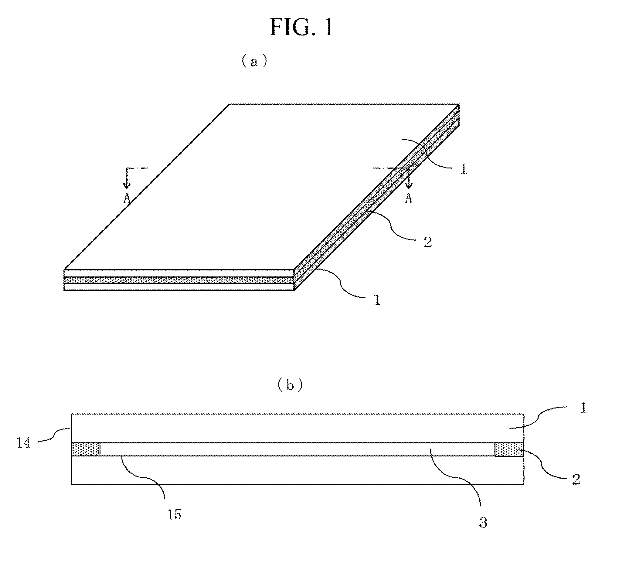
FIG. 1 illustrates an example of a sealed structural body, (a) showing a perspective view and (b) showing a cross sectional view.
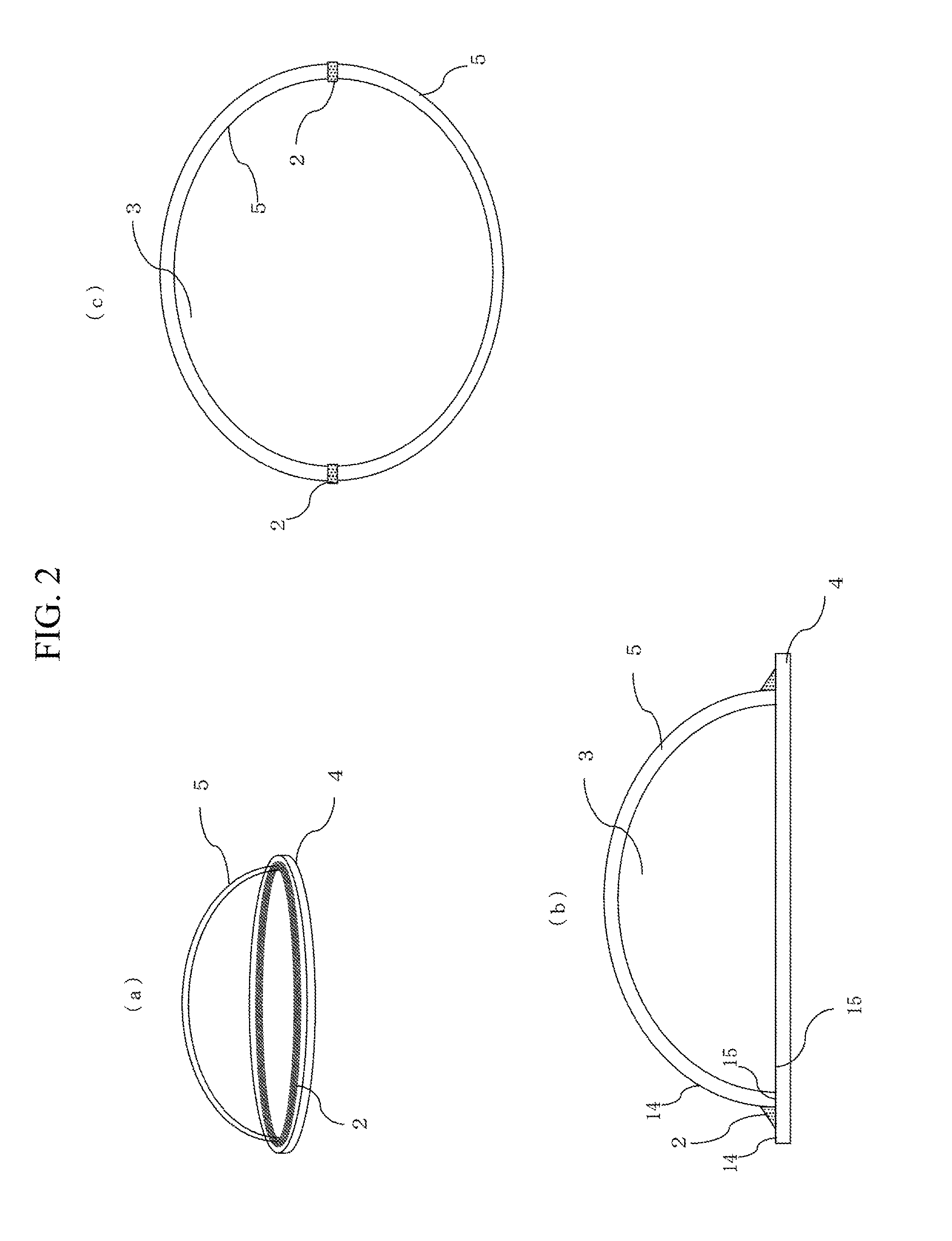
FIG. 2 illustrates an example of the sealed structural body, (a) showing a perspective view and (b) and (c) showing cross sectional views.
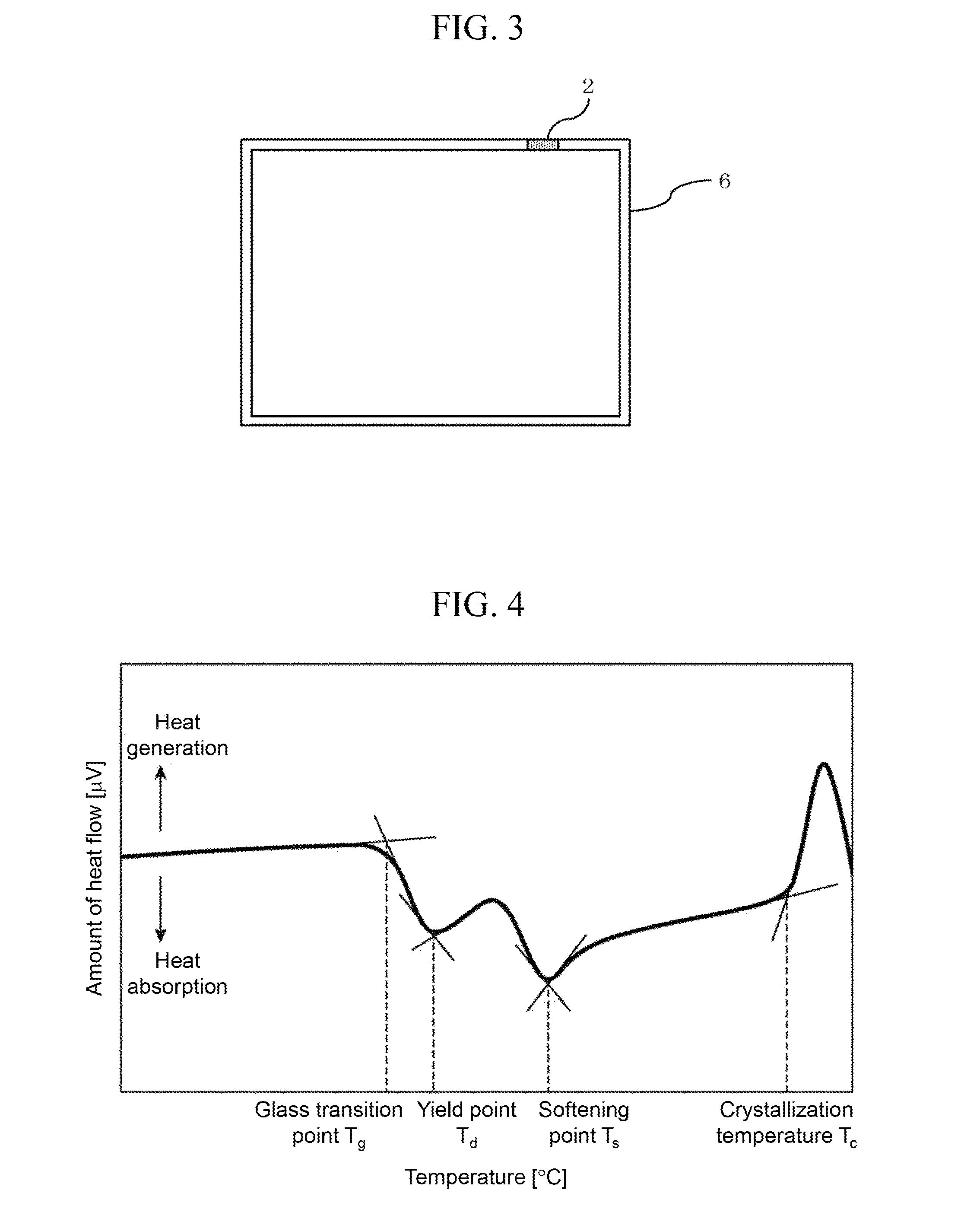
FIG. 3 illustrates an example of the sealed structural body.
FIG. 4 illustrates an example of differential thermal analysis results, and how various characteristic temperatures are determined.
FIG. 5 illustrates a method for analyzing bonding property.
FIG. 6 illustrates the wavelength dependency of light transmittance in a developed glass.
FIG. 7 shows cross sectional views of sealed structural bodies, (a) illustrating a case where a low melting point metallic filler is used, and (b) illustrating a case where a metallic filler with a large particle diameter is used.
FIG. 8 shows cross sectional views of double insulating glasses, (a) illustrating a case where sealing material is disposed between two glass plates, and (b) illustrating a case where sealing material is disposed on the outside.
DESCRIPTION OF EMBODIMENTS
While in the following, embodiments of the present invention will be described, the present invention is not limited to the embodiments. A sealed structural body refers to a glass structural body including an internal space separated from the outside by glass, as illustrated in FIGS. 1 to 3. The internal space may be formed by adhering a plurality of glass members using sealing material (bonding material), or by closing an opening of a single glass member with sealing material.
FIG. 1 illustrates an internal space 3 formed between two glass plates 1 the outer peripheries of which are adhered to each other using sealing material 2. FIG. 1(a) is a perspective view of the sealed structural body, and FIG. 1(b) is a cross sectional view taken along line A-A across the glass plates 1 and the sealing material 2. Such a structure is used in a heat-insulated window glass, an OLED display, and the like. In the heat-insulated window glass, normally, soda-lime glass is used for the glass plates 1, and the internal space 3 is either filled with argon gas, which has superior thermal insulating property to atmospheric air, or evacuated. On the other hand, in the OLED display, alkali-free glass is used for the glass plates 1, with an organic light-emitting diode sealed in the internal space 3. Other members may be disposed in the internal space 3, or the internal space 3 may be filled with another atmosphere.
The sealing material 2 may not only bond only opposed surfaces 15 of the glass plates 1, as illustrated in FIG. 1, but the material may also be present outside the sealed structural body (such as being attached to outer faces 14 of the plate glass 1). Instead of at the end portions, the opposed surfaces 15 may be bonded slightly inside the end portions. In other words, it is only required that the internal space 3 and the external space be separated by means of the two glass plates 1 and the sealing material 2.
When the interval of the glass plates 1 is increased, the volume of the sealing material 2 used is also increased. Because the sealing material 2 is irradiated with laser from outside the glass plates 1, the thicker the sealing material 2 becomes in the direction of propagation of laser, the harder it becomes for the laser to reach inside and thereby heat the sealing material 2. Also, it becomes more difficult for the heat provided by the heating of the sealing material 2 on the glass plate 1 side to reach the inside of the sealing material 2. However, by the sealing material having a glass compound and metal particles as will be described below, the sealing material, even when it has a large thickness in the direction of propagation of laser, can be caused to readily absorb laser energy in a spatially uniform manner, and have a spatially uniform temperature distribution. Accordingly, damage to the sealing material or the material to be bonded, and bonding failure such as interfacial peeling can be decreased.
FIG. 2 illustrates the internal space 3 formed by adhering the glass plate 4 and a bowl-shaped glass member 5 to each other with the sealing material 2. FIG. 2(a) is a perspective view of the sealed structural body; FIG. 2(b) is a cross sectional view taken across the glass plate 4, the bowl-shaped glass member 5, and the sealing material 2; and FIG. 2(c) is a cross sectional view of a structural body of bowl-shaped glass members 5 bonded to each other. The structures may be used for containers for insect specimens or ornamental dried flowers, for example. The internal space 3 may have a large size, and provides good internal visibility. By evacuating the internal space, degradation of the article placed therein can be delayed.
The sealing material 2 may not only bond the Mass plate 4 and the bowl-shaped glass member 5 by contacting their outer faces 14, as illustrated in FIG. 2(b), but may also bond the opposed surfaces 15 of the both members, as illustrated in FIG. 2(c). When at least one of the members to be bonded is curved, an internal space may be formed by contacting the to-be-bonded members to each other, and then bonding the members from outside with the sealing material so as to maintain airtightness.
When a plate having a curved surface is used as illustrated in FIG. 2, durability can be achieved even when the internal space is evacuated. Alternatively, rectangular members to be bonded may be used so as to form a columnar or cuboidal internal space, for example. Further alternatively, three or more members may be bonded.
When the article sealed inside is small or a liquid, for example, a single glass member 6 having an opening may be prepared as illustrated in FIG. 3, and the opening may be closed with the sealing material 2.
(Fabrication of Glass Compound)
Low melting point glass compounds (G1 to G31) for the sealing material were fabricated. The glass compounds according to the present invention do not include lead. The compositions and glass transition points of the fabricated glasses are shown in Table 1. The glasses were fabricated according to the following procedure.
Starting materials were weighed to achieve predetermined weight ratios. As the starting materials, oxide powders (purity 99.9%) from Kojundo Chemical Lab. Co., Ltd. were used. In some samples, as a Ba source and a P source, Ba(PO.sub.3).sub.2 from Rasa Industries, Ltd. was used. The starting materials were mixed and placed in a platinum crucible. When the ratio of Ag.sub.2O in raw material was 40 mass % or greater, an alumina crucible was used. The crucible with the raw material mixed powder placed therein was installed in a glass melting furnace, and heated and fused. While increasing the temperature at the temperature-increase rate of 10.degree. C./min, the glass being fused at a set temperature (700 to 950.degree. C.) was retained while stirring for one hour. The crucible was then taken out of the glass melting furnace, and the glass was cast into a graphite mold that had been previously heated to 150.degree. C. After cooling to room temperature, the glass was coarsely crushed, fabricating a glass compound frit. The glass compound frit had an average volume particle diameter of not more than 20 .mu.m.
The characteristic temperature of the fabricated glass frit was measured by differential thermal analysis (DTA). At the temperature-increase rate of 5.degree. C./min, data up to 600.degree. C. were acquired. For the standard sample, alumina powder was used, and for a sample container, Al was used. FIG. 4 illustrates a representative DTA curve. As illustrated, the glass transition point (T.sub.g) was the start temperature of a first heat absorption peak. Besides, as a first heat absorption peak temperature, a yield point (M.sub.g) was determined; as a second heat absorption peak temperature, a softening point (T.sub.s) was determined; and as a crystallization temperature, the start temperature (T.sub.c) of a heat generating peak was determined. The temperature suitable for adhesion depends on the particle diameter of glass, the pressurization condition and retention time during bonding, and the like, and therefore cannot be defined as a rule; it is necessary, though, to achieve at least a temperature higher than the softening point T.sub.s corresponding to the viscosity=10.sup.7.65 poise. The softening point T.sub.s may be considered to be a temperature higher than the glass transition temperature T.sub.g by approximately 50 to 100.degree. C., depending on the glass compound.
The glasses included V and Te, and further at least one of P or Ag. More specifically, in oxide equivalents, V2O5 was 17 to 50 mass %; TeO2 was 20 to 33 mass %; and P2O5 was 4.8 to 12 mass %. Alternatively, V2O5 was 17 to 45 mass %; TeO2 was 25 to 40 mass %; and Ag2O was 20 to 45 mass %. These values enabled the glass transition temperature to be set at 160 to 340.degree. C. Particularly, when the total of Ag2O, V2O5, and TeO2 in oxide equivalents was 85 mass % or greater of the glass compound, as for G11 to G31 in the table, very low values of glass transition temperature of 160 to 270.degree. C. were obtained.
TABLE-US-00001 TABLE 1 Glass transition Glass compound (mass %) temperature Glass V.sub.2O.sub.5 TeO.sub.2 Fe.sub.2O.sub.3 P.sub.2O.sub.5 Ag.sub.2O WO- .sub.3 BaO Sb.sub.2O.sub.3 K.sub.2O [.degree. C.] G1 50 32 10 8 -- -- -- -- -- 263 G2 50 30 10 6 -- 4 -- -- -- 257 G3 45 30 15 10 -- -- -- -- -- 308 G4 45 25 15 10 -- 5 -- -- -- 316 G5 43 30 15 12 -- -- -- -- -- 318 G6 37 33 19 11 -- -- -- -- -- 336 G7 38 30 -- 5.8 -- 10 11.2 -- 5 276 G8 55 20 -- 10 -- -- 5 10 -- 313 G9 45 25 -- 10 -- -- 5 15 -- 338 G10 45 30 -- 10.3 -- 10 4.7 -- -- 286 G11 30 30 -- 4.8 30 -- 5.2 -- -- 222 G12 30 30 -- 5 30 5 -- -- -- 230 G13 25 30 -- 4.8 30 5 5.2 -- -- 223 G14 25 30 -- 7.2 30 -- 7.8 -- -- 228 G15 30 30 -- 4.8 25 5 5.2 -- -- 236 G16 30 30 5 5 30 -- -- -- -- 235 G17 25 30 5 10 30 -- -- -- -- 266 G18 25 30 5 5 30 5 -- -- -- 249 G19 25 30 -- 5 30 10 -- -- -- 236 G20 30 30 -- 4.8 25 5 5.2 -- -- 237 G21 20 30 -- 4.8 35 5 5.2 -- -- 204 G22 17 30 -- 4.8 38 5 5.2 -- -- 197 G23 17 30 -- -- 43 5 5 -- -- 177 G24 20 35 -- -- 45 -- -- -- -- 163 G25 17 40 -- -- 43 -- -- -- -- 169 G26 40 40 -- -- 20 -- -- -- -- 218 G27 20 30 -- -- 45 5 -- -- -- 169 G28 45 30 -- -- 20 5 -- -- -- 224 G29 40 35 -- -- 25 -- -- -- -- 212 G30 18 34 -- -- 43 -- 5 -- -- 167 G31 40 25 -- -- 35 -- -- -- -- 235
(Fabrication of Sealing Material Paste)
Sealing material pastes were fabricated using the glass compounds. Of the fabricated pastes, facts of pastes P1 to P14 in which glasses G4 and G25 were used are shown in Table 2. Glass compound frits were pulverized using a jet mill. The particle diameter of the resultant powder was 1 to 2 .mu.m in volume weighted mean. Thereafter, the glass compounds and various fillers were mixed at predetermined compounding ratios. Mixing was performed using a agate mortar. With respect to the glass compounds G1 to G10, a solvent to which 4% of resin binder was added was mixed to prepare the paste. For the resin binder, ethyl cellulose was used; for the solvent, butyl carbitol acetate was used. Butyl carbitol acetate does not readily react with the glass compounds G1 to G10. However, because the solvent by itself has low viscosity and exhibits poor coating property, the resin binder was added. When heated to approximately 300.degree. C., the ethyl cellulose can be caused to evaporate and removed without causing the glass compounds G1 to G10 to become soft and flow. In other words, the pastes using the glass compounds G1 to G10 were used by being coated on a bonding base material and then heated to approximately 300.degree. C. so as to remove the solvent and resin binder.
Meanwhile, with respect to the glass compounds G11 to G31, only the solvent was mixed to prepare the paste. Herein, as the solvent, .alpha. terpineol was used. .alpha. terpineol does not readily react with the glass compounds G11 to G31; in addition, it has relatively high viscosity and can therefore provide good coating property without adding a resin binder. It should be noted that a terpineol cannot be used as a solvent with respect to the glass compounds G1 to G10 as it reacts with the compositions. .alpha. terpineol can be caused to evaporate when heated to approximately 100 to 150.degree. C. and can be therefore removed without causing the glass compounds G11 to G31 to become soft and flow.
The material of the added filler was the three types of Sn-3.5Ag, Ag, and phosphoric acid zirconium tungstate (ZWP:Zr.sub.2 (WO.sub.4)(PO.sub.4).sub.2). Ag was prepared in two types, one with small particle diameter and the other with large particle diameter.
TABLE-US-00002 TABLE 2 Filler Filler Filler particle melting volumetric Filler diameter point compounding Paste Glass material (.mu.m) (.degree. C.) ratio P1 G4 None -- -- 0 P2 Sn--3.5Ag 40 221 0.3 P3 0.5 P4 0.7 P5 Ag 1 961 0.7 P6 100 0.7 P7 ZWP <10 -- 0.3 P8 G25 None -- -- 0 P9 Sn--3.5Ag 40 221 0.2 P10 0.3 P11 0.4 P12 Ag 1 961 0.7 P13 100 0.7 P14 ZWP <10 -- 0.3
(Evaluation of Bonding Property)
Bonding property of pastes P1 to P14 was evaluated according to the following procedure.
A material to be bonded 81 was a soda-lime glass with a thickness of 0.3 mm. The soda-lime glass plate was coated with the paste using a screen printing machine. A coating film 79 had a width of 2 mm (FIG. 5(a)). The coating film 79 had five different thicknesses of 10, 40, 70, 100, and 200 .mu.m.
Pastes P1 to P7 were heated to 150.degree. C. to evaporate butyl carbitol acetate, and then heated to 320.degree. C. to remove ethyl cellulose, followed by pre-calcination under the condition of 400.degree. C. for 10 min. Pastes P8 to P14 were heated to 150.degree. C. to evaporate a terpineol, and then pre-calcined under the condition of 300.degree. C. for 10 min.
The coating film was further covered on top with the other soda-lime glass material to be bonded 82, and the coating film 7 was irradiated with laser from above the glass plate 82, as illustrated in FIG. 5(b). With the beam diameter fixed at 7 mm, laser output was gradually increased to investigate the best conditions.
The results of the experiments are shown in Table 3, where "Good" indicates good adhesion across the entire length after laser output adjustment, and "Poor" indicates absence of good adhesion no matter how the laser output was adjusted. No samples were fabricated under the condition in which the height of the coating film was smaller than the particle diameter of the filler, and such case is denoted by "-".
TABLE-US-00003 TABLE 3 Filler particle Filler volumetric Results with respect Filler diameter compounding to each film thickness Paste Glass material (.mu.m) ratio 10 40 70 100 200 P1 G4 None -- 0 Good Good Poor Poor Poor P2 Sn--3.5Ag 40 0.3 -- Good Poor Poor Poor P3 0.5 -- Good Good Poor Poor P4 0.7 -- Good Good Poor Poor P5 Ag 1 0.7 Good Good Poor Poor Poor P6 100 0.7 -- -- -- Poor Poor P7 ZWP <10 0.3 Good Good Poor Poor Poor P8 G25 None -- 0 Poor Poor Poor Poor Poor P9 Sn--3.5Ag 40 0.3 -- Good Poor Poor Poor P10 0.5 -- Good Good Good Poor P11 0.7 -- Good Good Good Good P12 Ag 1 0.7 Good Good Poor Poor Poor P13 100 0.7 -- -- -- Good Good P14 ZWP <10 0.3 Good Good Poor Poor Poor
From the results shown in Table 3, insights (A) to (E) were obtained.
(A) in the Absence of Filler, Glass with High Glass Transition Temperature should be Used.
When pastes P1 and P8 that did not contain filler are compared, in the case of paste P1 in which glass with high glass transition temperature was used, good adhesion was achieved even when the film thickness was increased to 40 .mu.m.
The thermal expansion coefficient of glasses G1 to G10 was 8 to 16 ppm/K. The thermal expansion coefficient of glasses G11 to G31 was 13 to 18 ppm/K. The former glass, with a higher glass transition temperature, tends to have a lower thermal expansion coefficient than the latter glass. Meanwhile, the thermal expansion coefficient of soda-lime glass is 7 ppm/K. Accordingly, it is believed that in the sealing material with high glass transition temperature, the difference in thermal expansion coefficient from the glass base material is decreased, resulting in decreased residual stress after adhesion, and providing good adhesion.
However, when the film thickness was greater than 70 .mu.m, good adhesion was not achieved even if paste P1 containing high glass transition temperature glass was used.
(B) When the Film Thickness is Small, ZWP May Preferably be Contained in the Filler.
In the case where glass G25 having low glass transition temperature was used, when paste P8 not containing the filler and paste P14 containing ZWP are compared, it can be seen that by using ZWP in the filler, good adhesion was obtained only when the film thickness was 40 .mu.m or smaller. This is attributed to the fact that, when the filler contains ZWP having low thermal expansion coefficient, the thermal expansion coefficient of the sealing material becomes closer to that of the soda-lime glass, thereby providing good adhesion.
However, when the film thickness was greater than 70 .mu.m, good adhesion was not obtained even if ZWP was used in the filler.
(C) When the Film Thickness is Large, Metallic Filler May Preferably be Added.
When the film thickness was on the order of 40 .mu.m, good adhesion was obtained by controlling the thermal expansion coefficient. However, when the film thickness was greater than 70 .mu.m, good adhesion could not be achieved. However, in pastes P3, 4, 11, and 13, good adhesion was obtained even when the film thickness was greater than 70 .mu.m. These pastes commonly contain a metallic filler (metal material). According to the present invention, the metallic filler refers to a filler including a metal that has not formed an oxide. In the following, the reason for the effectiveness of the metallic filler content when the film thickness was large will be considered.
FIG. 6 illustrates the wavelength dependency of light transmittance in the film with the thickness of 5 .mu.m fabricated according to glass number 24. The result shows that, when laser with the wavelength of 1000 nm was used, for example, approximately 40% of the laser energy was absorbed at the depth of 5 .mu.m from the laser irradiated side, so that approximately 60% of the laser energy reached regions of greater depths. Accordingly, when the film thickness is large, the amount of laser energy absorption significantly varies depending on the film depth. In addition, the thermal conductivity of the presently fabricated glasses was low at approximately 0.5 W/mK regardless of the composition, so that heat was not readily diffused. As a result, during heating by laser, large temperature non-uniformity is caused within the coating film. The temperature non-uniformity increases the residual stress after bonding, possibly causing bonding failure, such as a crack. However, it is believed that, when the metallic filler is added, the thermal conductivity of the sealing material is increased, whereby the non-uniform temperature distribution at the time of laser irradiation is mitigated, making it possible to obtain good adhesion. Examples of the metallic filler include not only those containing Ag or Sn but also those containing Cu, Al, Zn, Au, In, Bi, or Pt.
(D) When the Film Thickness is Large, Metallic Filler May be Added, and Further Glass with a Composition Having Low Glass Transition Temperature May Preferably be Used.
When pastes P3, 4, and 6 pastes P10, 11, and 13 are compared, good adhesion was obtained in the case of pastes P10, 11, and 13 even when the film thickness was greater than 100 .mu.m. These pastes commonly had a metallic filler added therein, and in addition, they used glasses of compositions with low glass transition temperature. The use of glass with compositions with low glass transition temperature enables the amount of temperature increase required for adhesion at the time of laser irradiation to be reduced, whereby the temperature non-uniformity in the coating film is decreased. As a result, it is believed, the residual stress after adhesion was decreased, whereby adhesion failure was prevented.
(E) When the Film Thickness is Large, a Low Melting Point Metallic Filler should be Used, or a Metallic Filler with Large Particle Diameter should be Used.
Pastes P11, 12, and 13 are compared. Despite these pastes have the same ratio of metallic filler added to glass (glass:metallic filler=1:0.7), only P12 had a narrow range of bondable film thickness (i.e., good adhesion could not be obtained when the film thickness was large). When a metallic filler is added, the thermal conductivity of the sealing member is increased, making it easier to make the sealing member temperature uniform at the time of laser irradiation. On the other hand, when the amount of metallic filler added is increased, the flowability of the sealing member may deteriorate, resulting in an increase in voids or defects. Such disadvantages can be avoided by using a metallic filler having a lower melting point than the softening point of glass, or a metallic filler with large particle diameter.
When the metallic filler having a lower melting point than the softening point at which glass begins to flow is selected, a decrease in flowability can be mitigated and formation of good adhesion can be facilitated. When the metallic filler with low melting point is used, the sealed structural body has a cross section as illustrated in FIG. 7(a). The metallic filler 12 between the materials to be bonded 81, 82 is melted by laser heating, whereby the metallic filler portions are bonded to each other, and gaps of the metallic filler 12 are filled with glass 13. However, the heating time of laser irradiation is short, so that the original particle shape is maintained.
When the particle diameter of the metallic filler is large, the gaps between the metallic filler particles are increased, whereby the glass that has become soft and flowable can readily penetrate the gaps. As a result, the glass that has become soft and flowable can penetrate the gaps of the metallic filler particles sufficiently, making it possible to obtain good adhesion. Preferably, the metallic filler may be used in a range of 0.5 to 1 times the thickness of the coating film. When this range of size of the metallic filler is used, the metallic filler 12 will have an aligned structure as illustrated in FIG. 7(b). The energy supplied by laser irradiation via the metallic filler can extend from the laser irradiated surface to far regions, achieving a uniform temperature distribution.
The above analysis of sealing property will be summarized. An important point when the film thickness is thin is to align the thermal expansion coefficient between the base material and the sealing member as much as possible. However, when the film thickness is large, good adhesion cannot be obtained if only the thermal expansion coefficient is considered. This is because the energy density of laser absorbed by the coating film is attenuated with respect to the film depth direction, whereby the internal temperature distribution of the coating film becomes greatly non-uniform. The inventors have discovered that in order to prevent such temperature distribution non-uniformity, it is effective to mix a metallic filler in the sealing member. The inventors have also discovered that it is effective to use a glass compound containing V, Te, and Ag as components and having a low glass transition temperature. In addition, it has also been discovered that a metallic filler with a low melting point or a large particle diameter can be effectively used.
That good bonding can be obtained when the film thickness is increased provides the following advantages. First, in the case of the structure in which two glass plates are bonded, as illustrated in FIG. 1, the thickness of the internal space can be increased. Secondly, bonding can also be achieved when the sealing structure is such that, as illustrated in FIGS. 2 and 3, it is difficult to control the thickness of the bonding material paste. In the following, an embodiment utilizing such advantages will be described.
(Embodiment in the Case of Double Insulating Glass)
FIG. 8 illustrates a cross sectional structure of a double insulating glass. The modes of heat transmission between the two glass plates 9 include thermal conduction and convection by the gas in the space, and radiation in the form of electromagnetic wave energy. Assuming that the interior of the space is a vacuum (an atmosphere with reduced pressure relative to the atmospheric air), the thermal conduction and convection by gas are eliminated, so that the thermal insulating performance can be increased. However, when the space is a vacuum, it is difficult to maintain an interval between the two glass plates because of external pressure. Accordingly, a spacer 10 is installed in the space. In this case, the thermal conduction by the spacer 10 poses a factor causing a decrease in thermal insulating property. In order to prevent the increase in thermal insulating performance by the evacuated space from being cancelled by the thermal conduction due to the spacer 10, it is necessary to provide a gap of at least 0.1 mm and preferably 0.2 mm between the two glass plates 9. Further, in order to maintain the vacuum in the space, the sealing material employs a material with excellent gas barrier property, such as low melting point glass. The sealing material 11 may be sandwiched between the two glass plates as illustrated in FIG. 8(a), or disposed at the end of one of the glasses, as illustrated in FIG. 8(b). In either case, in the double insulating glass, it is necessary to separate the two glass plates 9 from each other, and to use a thick film for the sealing material 11. Accordingly, when manufacturing by laser heating, the above-described insights (C) to (E) may preferably be utilized. The double insulating glass can be fabricated by the following method, for example.
After paste P11 is coated on the outer periphery of a soda-lime glass plate with a thickness of 3 mm, heating is performed at 150.degree. C. to evaporate a terpineol, followed by pre-calcination at 300.degree. C. for 10 minutes. The thickness of the spacer may be 0.2 mm, and the thickness of the coating film may be 0.25 mm. Another soda-lime glass plate with a thickness of 3 mm is placed and scanned along the coating film with laser with a wavelength of 1030 nm. Due to the weight of the soda-lime glass plate, as laser scan proceeds, the coating film becomes molten and spreads until the interval of the two Mass plates becomes equal to the height of the spacer, i.e., 0.2 mm One of the soda-lime glass plates is provided with a vacuum exhaust opening in advance. After the internal air is discharged via the opening using a rotary pump, the vacuum exhaust opening can be melted by a gas burner to achieve a vacuum seal. Alternatively, laser scan may be performed in the vacuum, whereby vacuum seal can be achieved without subsequent evacuation. In this case, the need for providing the vacuum exhaust opening can be eliminated, which may be preferable in terms of exterior view.
Thus, using laser heating during manufacture of the double insulating glass provides the advantage that a thermally sensitive article can be installed between the two glass plates. For example, the window glass can be provided with a new function by affixing a film with a dimmer, anti-reflection, or heat ray reflection function on the inside of one of the glass plates. In addition, because the film is installed on the vacuum heat-insulated layer, degradation by moisture or dust can be prevented. Alternatively, an illumination element, an image display element, or the like may be installed on the vacuum heat-insulated layer. In the case of store windows of shops and the like, the internal merchandise may be illuminated by the illumination element or information about the merchandise may be projected on the image display element as needed so as to enable confirmation of the merchandise. Such configuration may be preferably used in a commercial facility.
(Embodiment as a Preservation Container for Insect Specimen or Fresh Flowers)
Insect specimen, fresh flowers, and the like, if kept in the atmospheric air, tend to lose color or shape due to oxidation or moisture absorption. Accordingly, for such purposes, it is desirable to lower humidity and preserve the content in an inert atmosphere.
In a method for sealing insect specimen, fresh flower and the like in an inert gas in such a way as to enable internal observation at any time, the insect specimen or the fresh flower is installed in an internal space formed between the glass plate 4 as a bottom plate and the bowl-shaped glass member 5, as illustrated in FIG. 2, the bottom plate and the hemispherical transparent member are adhered each other with the sealing material, and then an inert gas such as argon is sealed in the internal space 3, for example. For the glass plate 4, the bowl-shaped glass member 5, and the sealing material 2, it is preferable to use glass with its superior gas barrier property, rather than organic material, such as resin. However, while the insect specimen and fresh flower are sensitive to heat, the glass sealing material needs to be heated to the glass melting temperature during the sealing process. In this case, by utilizing laser heating, only the sealing material portion can be heated and melted without causing damage to the internal insect specimen or fresh flower. The sealing material may be simply coated along the outer edge of the hemispherical transparent member, as illustrated in FIG. 8. However, it is very difficult to coat such a form of coating film with a uniform thickness, and therefore it is also difficult to uniformly heat the sealing material during laser heating. Accordingly, the above-described insights (C) to (E) may be utilized. Preservation of the insect specimen, fresh flower and the like can be achieved by the following method, for example.
The insect specimen or fresh flower is placed on a soda-lime glass bottom plate. After the atmosphere is replaced with an inert gas such as argon, a soda-lime Mass hemispherical transparent member is placed thereon. The outer peripheries of the bottom plate and the hemispherical transparent member are coated with paste P11. Along the coated paste, laser with a wavelength of 1030 nm is scanned. As a result, the solvent in the paste is evaporated and the glass particles and tin particles are melted, whereby the bottom plate and the hemispherical transparent member become adhered to each other, while separating the internal space from the outside. Thereafter, the inert gas sealed state can be maintained even when placed in the atmospheric air.
REFERENCE SIGNS LIST
1 Glass plate 2 Sealing material 3 Internal space 4 Glass plate 5 Bowl-shaped glass member 6 Glass member 7 Coating film 81 Material to be bonded 82 Material to be bonded 9 Glass plate 10 Spacer 11 Sealing material 12 Metallic filler 13 Lead-free glass compound 14 Outer face 15 Opposed surface
* * * * *
D00000
D00001
D00002
D00003
D00004
D00005
D00006
D00007
XML
uspto.report is an independent third-party trademark research tool that is not affiliated, endorsed, or sponsored by the United States Patent and Trademark Office (USPTO) or any other governmental organization. The information provided by uspto.report is based on publicly available data at the time of writing and is intended for informational purposes only.
While we strive to provide accurate and up-to-date information, we do not guarantee the accuracy, completeness, reliability, or suitability of the information displayed on this site. The use of this site is at your own risk. Any reliance you place on such information is therefore strictly at your own risk.
All official trademark data, including owner information, should be verified by visiting the official USPTO website at www.uspto.gov. This site is not intended to replace professional legal advice and should not be used as a substitute for consulting with a legal professional who is knowledgeable about trademark law.