Negative pressure wound therapy orthopedic device
Walborn , et al. A
U.S. patent number 10,391,211 [Application Number 15/006,278] was granted by the patent office on 2019-08-27 for negative pressure wound therapy orthopedic device. This patent grant is currently assigned to Ossur Iceland ehf. The grantee listed for this patent is Ossur Iceland ehf. Invention is credited to Janaki Ram-srinivasaRao Chetlapalli, Gudni Ingimarsson, Jonathan Walborn.


| United States Patent | 10,391,211 |
| Walborn , et al. | August 27, 2019 |
Negative pressure wound therapy orthopedic device
Abstract
A negative pressure wound therapy (NPWT) orthopedic device includes a base shell and a dorsal shell contoured to generally correspond to an opening of the base shell. The dorsal shell includes a proximal section and a distal section. The proximal section at least in part defines a receiving space. A NPWT system includes a pump mechanism secured in the receiving space and a wound covering situated inside of the base shell and arranged to form a sealed volume over a wound area of a user. At least one conduit forms a fluid connection between the wound covering and the pump mechanism. The pump mechanism is arranged to apply a negative pressure to the wound area through the at least one conduit.
| Inventors: | Walborn; Jonathan (Mission Viejo, CA), Chetlapalli; Janaki Ram-srinivasaRao (Irvine, CA), Ingimarsson; Gudni (Reykjavik, IS) | ||||||||||
|---|---|---|---|---|---|---|---|---|---|---|---|
| Applicant: |
|
||||||||||
| Assignee: | Ossur Iceland ehf (Reykjavik,
IS) |
||||||||||
| Family ID: | 55487044 | ||||||||||
| Appl. No.: | 15/006,278 | ||||||||||
| Filed: | January 26, 2016 |
Prior Publication Data
| Document Identifier | Publication Date | |
|---|---|---|
| US 20160213823 A1 | Jul 28, 2016 | |
Related U.S. Patent Documents
| Application Number | Filing Date | Patent Number | Issue Date | ||
|---|---|---|---|---|---|
| 62107636 | Jan 26, 2015 | ||||
| Current U.S. Class: | 1/1 |
| Current CPC Class: | A61F 5/0111 (20130101); A61F 13/00068 (20130101); A61M 1/0023 (20130101); A61F 13/0216 (20130101); A61M 1/0088 (20130101); A61F 5/0102 (20130101); A61M 2210/086 (20130101); A61M 2209/088 (20130101) |
| Current International Class: | A61M 1/00 (20060101); A61F 13/00 (20060101); A61F 13/02 (20060101); A61F 5/01 (20060101) |
References Cited [Referenced By]
U.S. Patent Documents
| 975576 | November 1910 | Sexton |
| 1012017 | December 1911 | Salt |
| 2200849 | May 1940 | Margolin |
| 2236367 | March 1941 | Gruber |
| 2292297 | August 1942 | Sherlock |
| 2444640 | July 1948 | Epstein |
| 2868191 | January 1959 | Juhasz |
| 2885797 | May 1959 | Chrencik |
| 2888016 | May 1959 | De Lamater |
| 2909854 | October 1959 | Edelstein |
| 2913837 | November 1959 | Geuder |
| 2917844 | December 1959 | Scholl |
| 2928193 | March 1960 | Kristan |
| 2979835 | April 1961 | Scholl |
| 2979836 | April 1961 | Scholl |
| 3270358 | September 1966 | Milner |
| 3464126 | September 1969 | Sarkissian |
| 3548420 | December 1970 | Spence |
| 3580248 | May 1971 | Larson |
| 3681860 | August 1972 | Bidegain |
| 3685176 | August 1972 | Rudy |
| 3730169 | May 1973 | Fiber |
| 3735758 | May 1973 | Novotney |
| 3760056 | September 1973 | Rudy |
| 3786805 | January 1974 | Tourin |
| 3792537 | February 1974 | Plank et al. |
| 3814088 | June 1974 | Raymond |
| 3834377 | September 1974 | Lebold |
| 3859740 | January 1975 | Kemp |
| 3922800 | December 1975 | Miller et al. |
| 3955565 | May 1976 | Johnson, Jr. |
| 4045888 | September 1977 | Oxenberg |
| 4057056 | November 1977 | Payton |
| 4095353 | June 1978 | Foldes |
| 4100686 | July 1978 | Sgarlato et al. |
| 4142307 | March 1979 | Martin |
| 4177583 | December 1979 | Chapman |
| 4184273 | January 1980 | Boyer et al. |
| 4217706 | August 1980 | Vartanian |
| 4217893 | August 1980 | Payton |
| 4232459 | November 1980 | Vaccari |
| 4237626 | December 1980 | Brown |
| 4267649 | May 1981 | Smith |
| 4300294 | November 1981 | Riecken |
| 4333248 | June 1982 | Samuels |
| 4370818 | February 1983 | Simoglou |
| 4408402 | October 1983 | Looney |
| 4414965 | November 1983 | Mauldin et al. |
| D272281 | January 1984 | Alush |
| 4446856 | May 1984 | Jordan |
| 4494536 | January 1985 | Latenser |
| 4505269 | March 1985 | Davies et al. |
| 4550721 | November 1985 | Michel |
| 4565017 | January 1986 | Ottieri |
| 4571853 | February 1986 | Medrano |
| 4572169 | February 1986 | Mauldin et al. |
| 4587962 | May 1986 | Greene et al. |
| 4598484 | July 1986 | Ma |
| 4599811 | July 1986 | Rousseau |
| 4608768 | September 1986 | Cavanagh |
| 4620378 | November 1986 | Sartor |
| 4633598 | January 1987 | Moronaga et al. |
| 4633599 | January 1987 | Morell et al. |
| 4633877 | January 1987 | Pendergast |
| 4660300 | April 1987 | Morell et al. |
| 4669202 | June 1987 | Ottieri |
| 4674204 | June 1987 | Sullivan et al. |
| 4674205 | June 1987 | Anger |
| 4677767 | July 1987 | Darby |
| 4680878 | July 1987 | Pozzobon et al. |
| 4689898 | September 1987 | Fahey |
| 4719710 | January 1988 | Pozzobon |
| 4727661 | March 1988 | Kuhn |
| 4741115 | May 1988 | Pozzobon |
| 4748726 | June 1988 | Schoch |
| 4760653 | August 1988 | Baggio |
| 4771768 | September 1988 | Crispin |
| 4773170 | September 1988 | Moore et al. |
| 4793078 | December 1988 | Andrews |
| D299787 | February 1989 | Bates |
| 4805321 | February 1989 | Tonkel |
| 4805601 | February 1989 | Eischen, Sr. |
| 4811504 | March 1989 | Bunke |
| 4869001 | September 1989 | Brown |
| 4872273 | October 1989 | Smeed |
| 4879822 | November 1989 | Hayes |
| 4893418 | January 1990 | Ogden |
| 4934355 | June 1990 | Porcelli |
| 4947838 | August 1990 | Giannetti |
| 4974583 | December 1990 | Freitas |
| 5065481 | November 1991 | Walkhoff |
| 5065531 | November 1991 | Prestridge |
| 5078128 | January 1992 | Grim et al. |
| 5123180 | June 1992 | Nannig et al. |
| 5125400 | June 1992 | Johnson, Jr. |
| D329527 | September 1992 | Cohen |
| 5143058 | September 1992 | Luber et al. |
| D330109 | October 1992 | Hatfield |
| 5152038 | October 1992 | Schoch |
| 5154682 | October 1992 | Kellerman |
| 5154695 | October 1992 | Farris et al. |
| 5157813 | October 1992 | Carroll |
| 5176623 | January 1993 | Stetman et al. |
| 5176624 | January 1993 | Kuehnreich |
| 5183036 | February 1993 | Spademan |
| 5197942 | March 1993 | Brady |
| D334646 | April 1993 | Dissinger |
| D337876 | August 1993 | Kilbey |
| 5233767 | August 1993 | Kramer |
| 5242379 | September 1993 | Harris et al. |
| 5257470 | November 1993 | Auger et al. |
| 5277695 | January 1994 | Johnson, Jr. et al. |
| D344589 | February 1994 | Kilbey |
| 5288286 | February 1994 | Davis et al. |
| 5325613 | July 1994 | Sussmann |
| 5329705 | July 1994 | Grim et al. |
| D352191 | November 1994 | Zorian |
| D352784 | November 1994 | Cohen et al. |
| 5359791 | November 1994 | Prahl et al. |
| 5368549 | November 1994 | McVicker |
| 5368551 | November 1994 | Zuckerman |
| 5370133 | December 1994 | Darby et al. |
| 5378223 | January 1995 | Grim et al. |
| 5399152 | March 1995 | Habermeyer et al. |
| 5407421 | April 1995 | Goldsmith |
| 5425701 | June 1995 | Oster et al. |
| 5426872 | June 1995 | Hayes |
| 5429377 | July 1995 | Duer |
| 5429588 | July 1995 | Young et al. |
| 5433695 | July 1995 | Drennan |
| 5435009 | July 1995 | Schild et al. |
| 5438768 | August 1995 | Bauerfeind |
| 5441015 | August 1995 | Farley |
| D363780 | October 1995 | Darby et al. |
| 5464385 | November 1995 | Grim |
| 5477593 | December 1995 | Leick |
| D365919 | January 1996 | Chen |
| 5483757 | January 1996 | Frykberg |
| 5496263 | March 1996 | Fuller, II et al. |
| 5548848 | August 1996 | Huybrechts |
| D373548 | September 1996 | Losi, II |
| 5558627 | September 1996 | Singer et al. |
| D375191 | November 1996 | Tonkel et al. |
| 5577998 | November 1996 | Johnson, Jr. et al. |
| D376429 | December 1996 | Antar |
| 5617650 | April 1997 | Grim |
| D379258 | May 1997 | Cheng |
| 5641322 | June 1997 | Silver et al. |
| 5647104 | July 1997 | James |
| 5656226 | August 1997 | McVicker |
| D383250 | September 1997 | Amico |
| D384746 | October 1997 | Varn |
| D390345 | February 1998 | Aird et al. |
| 5717996 | February 1998 | Feldmann |
| D391748 | March 1998 | Koh |
| 5761834 | June 1998 | Grim et al. |
| 5778563 | July 1998 | Ahlbaumer |
| 5778565 | July 1998 | Holt et al. |
| 5797862 | August 1998 | Lamont |
| D398142 | September 1998 | Benoit |
| D398439 | September 1998 | McDonald |
| 5819378 | October 1998 | Doyle |
| 5827210 | October 1998 | Antar et al. |
| 5827211 | October 1998 | Sellinger |
| D401042 | November 1998 | Davis |
| 5833639 | November 1998 | Nunes et al. |
| 5836902 | November 1998 | Gray |
| 5846063 | December 1998 | Lakic |
| 5853380 | December 1998 | Miller |
| 5857987 | January 1999 | Habermeyer |
| D404895 | February 1999 | Rosato |
| 5868690 | February 1999 | Eischen, Sr. |
| 5913841 | June 1999 | Lamont |
| 5934599 | August 1999 | Hammerslag |
| 5951504 | September 1999 | Iglesias et al. |
| 5961477 | October 1999 | Turtzo |
| 5993404 | November 1999 | Mc Niel |
| 6000148 | December 1999 | Cretinon |
| D418967 | January 2000 | Stengel |
| 6021780 | February 2000 | Darby |
| 6027468 | February 2000 | Pick |
| 6044578 | April 2000 | Kelz |
| 6098315 | August 2000 | Hoffmann, III |
| 6131195 | October 2000 | Foreman |
| 6202953 | March 2001 | Hammerslag |
| 6205685 | March 2001 | Kellerman |
| D440754 | April 2001 | Bathum |
| 6228044 | May 2001 | Jensen et al. |
| 6267742 | July 2001 | Krivosha et al. |
| RE37338 | August 2001 | McVicker |
| 6289558 | September 2001 | Hammerslag |
| 6334854 | January 2002 | Davis |
| 6338768 | January 2002 | Chi |
| 6361514 | March 2002 | Brown et al. |
| 6377178 | April 2002 | Detoro et al. |
| 6409691 | June 2002 | Dakin et al. |
| D461936 | August 2002 | Fiorini et al. |
| 6432073 | August 2002 | Pior et al. |
| D467708 | December 2002 | Portzline |
| D473654 | April 2003 | Iglesias et al. |
| D473704 | April 2003 | Wilson |
| 6572571 | June 2003 | Lowe |
| D476799 | July 2003 | Fuerst |
| 6589194 | July 2003 | Calderon et al. |
| 6682497 | January 2004 | Jensen et al. |
| 6755798 | June 2004 | McCarthy et al. |
| 6792699 | September 2004 | Long et al. |
| D500855 | January 2005 | Pick et al. |
| 6866043 | March 2005 | Davis |
| D504005 | April 2005 | Schoenborn et al. |
| D505727 | May 2005 | Krahner et al. |
| 6945944 | September 2005 | Kuiper et al. |
| 6976972 | December 2005 | Bradshaw |
| 6991613 | January 2006 | Sensabaugh |
| D517306 | March 2006 | Hoeft |
| 7010823 | March 2006 | Baek |
| 7018351 | March 2006 | Iglesias et al. |
| D523217 | June 2006 | Matis et al. |
| D528214 | September 2006 | Binet |
| 7198610 | April 2007 | Ingimundarson et al. |
| 7281341 | October 2007 | Reagan et al. |
| 7288076 | October 2007 | Grim et al. |
| D554835 | November 2007 | Peydro |
| D555291 | November 2007 | Danzo |
| D555343 | November 2007 | Bettencourt |
| 7303538 | December 2007 | Grim et al. |
| 7311686 | December 2007 | Iglesias et al. |
| 7354411 | April 2008 | Perry et al. |
| RE40363 | June 2008 | Grim et al. |
| 7384584 | June 2008 | Jerome et al. |
| D575039 | August 2008 | Amado et al. |
| D576781 | September 2008 | Chang et al. |
| 7418755 | September 2008 | Bledsoe et al. |
| D583544 | December 2008 | Fuerst |
| D583956 | December 2008 | Chang et al. |
| 7493706 | February 2009 | Cho et al. |
| 7524295 | April 2009 | Peters et al. |
| D592755 | May 2009 | Chang et al. |
| D592756 | May 2009 | Chang et al. |
| D594368 | June 2009 | Butler |
| D596301 | July 2009 | Campos et al. |
| D596386 | July 2009 | Brambilla |
| 7591050 | September 2009 | Hammerslag |
| D603155 | November 2009 | Della Valle et al. |
| D614775 | April 2010 | Snively |
| D615285 | May 2010 | Martin |
| D616556 | May 2010 | Hu |
| 7717869 | May 2010 | Eischen, Sr. |
| 7727174 | June 2010 | Chang et al. |
| D622494 | August 2010 | Warren |
| 7838717 | November 2010 | Haggstrom et al. |
| D634438 | March 2011 | Hu |
| D634852 | March 2011 | Hu |
| D636157 | April 2011 | Nascimento |
| D636159 | April 2011 | Petrie |
| 7964766 | June 2011 | Blott et al. |
| D642363 | August 2011 | Rajmohan et al. |
| D642775 | August 2011 | Raysse |
| 8002724 | August 2011 | Hu et al. |
| 8012112 | September 2011 | Barberio |
| 8021347 | September 2011 | Vitaris et al. |
| D648113 | November 2011 | Chang |
| RE43063 | January 2012 | Kim |
| D651381 | January 2012 | Simms |
| 8158844 | April 2012 | McNeil |
| D661887 | June 2012 | Petrie |
| 8308705 | November 2012 | Lin et al. |
| 8313449 | November 2012 | Hardman et al. |
| D675421 | February 2013 | Petrie |
| D677866 | March 2013 | Vestuti et al. |
| D680728 | April 2013 | Stryjak |
| D682517 | May 2013 | Taylor |
| D683214 | May 2013 | McAdam |
| D684760 | June 2013 | Williams, Jr. |
| 8506510 | August 2013 | Hu et al. |
| D689677 | September 2013 | Bathum et al. |
| 8574181 | November 2013 | Bird et al. |
| D696499 | December 2013 | Lehtinen |
| D696785 | December 2013 | Weaver, II et al. |
| D698074 | January 2014 | Hargreaves |
| D698338 | January 2014 | Ingham et al. |
| D700404 | February 2014 | Niefer |
| D701032 | March 2014 | Leleu |
| D701033 | March 2014 | Leleu |
| D703335 | April 2014 | Bird et al. |
| D709277 | July 2014 | Takenaka |
| D712639 | September 2014 | Spring |
| D714042 | September 2014 | Petrie |
| 9003677 | April 2015 | Goodsmith et al. |
| D729393 | May 2015 | Dunn et al. |
| D740896 | October 2015 | Halper, Jr. |
| D742017 | October 2015 | Dunn et al. |
| D744111 | November 2015 | Dunn et al. |
| 9220621 | December 2015 | Hu et al. |
| 9220622 | December 2015 | Ingimundarson et al. |
| 9248042 | February 2016 | Lopez et al. |
| 9333106 | May 2016 | Hu et al. |
| 9468553 | October 2016 | Hu et al. |
| D772418 | November 2016 | Li et al. |
| 9492301 | November 2016 | Hu et al. |
| D776288 | January 2017 | Dunn et al. |
| D776289 | January 2017 | Dunn et al. |
| 9668907 | June 2017 | Romo et al. |
| 9744065 | August 2017 | Walborn et al. |
| 9839548 | December 2017 | Ingvarsson et al. |
| 9839549 | December 2017 | Walborn et al. |
| 9839550 | December 2017 | Walborn et al. |
| 2002/0095105 | July 2002 | Jensen |
| 2002/0095750 | July 2002 | Hammerslag |
| 2002/0128574 | September 2002 | Darby |
| 2003/0093882 | May 2003 | Gorza et al. |
| 2003/0171703 | September 2003 | Grim et al. |
| 2003/0204938 | November 2003 | Hammerslag |
| 2004/0010212 | January 2004 | Kuiper et al. |
| 2004/0019307 | January 2004 | Grim et al. |
| 2004/0167453 | August 2004 | Peters |
| 2005/0131324 | June 2005 | Bledsoe |
| 2005/0145256 | July 2005 | Howard et al. |
| 2005/0165338 | July 2005 | Iglesias et al. |
| 2005/0171461 | August 2005 | Pick |
| 2005/0172517 | August 2005 | Bledsoe et al. |
| 2005/0274046 | December 2005 | Schwartz |
| 2006/0084899 | April 2006 | Verkade et al. |
| 2006/0135899 | June 2006 | Jerome et al. |
| 2006/0135902 | June 2006 | Ingimundarson et al. |
| 2006/0156517 | July 2006 | Hammerslag et al. |
| 2006/0189907 | August 2006 | Pick et al. |
| 2006/0217649 | September 2006 | Rabe |
| 2006/0229541 | October 2006 | Hassler et al. |
| 2007/0055188 | March 2007 | Avni et al. |
| 2007/0167884 | July 2007 | Mangrum et al. |
| 2007/0169378 | July 2007 | Sodeberg et al. |
| 2007/0185425 | August 2007 | Einarsson et al. |
| 2007/0191749 | August 2007 | Barberio |
| 2007/0282230 | December 2007 | Valderrabano et al. |
| 2007/0293798 | December 2007 | Hu et al. |
| 2008/0060167 | March 2008 | Hammerslag et al. |
| 2008/0060168 | March 2008 | Hammerslag et al. |
| 2008/0066272 | March 2008 | Hammerslag et al. |
| 2008/0066345 | March 2008 | Hammerslag et al. |
| 2008/0066346 | March 2008 | Hammerslag et al. |
| 2008/0083135 | April 2008 | Hammerslag et al. |
| 2008/0294082 | November 2008 | Chang et al. |
| 2008/0294083 | November 2008 | Chang et al. |
| 2009/0012482 | January 2009 | Pinto et al. |
| 2009/0099495 | April 2009 | Campos et al. |
| 2009/0227927 | September 2009 | Frazer |
| 2009/0234260 | September 2009 | Coward |
| 2009/0270820 | October 2009 | Johnson et al. |
| 2009/0287127 | November 2009 | Hu et al. |
| 2009/0287128 | November 2009 | Ingimundarson et al. |
| 2010/0069808 | March 2010 | Mitchell |
| 2010/0100020 | April 2010 | Fout et al. |
| 2010/0234782 | September 2010 | Hu et al. |
| 2010/0324461 | December 2010 | Darby, II et al. |
| 2011/0009791 | January 2011 | Hopmann |
| 2011/0015555 | January 2011 | Anderson et al. |
| 2011/0196275 | August 2011 | Chang et al. |
| 2012/0010534 | January 2012 | Kubiak et al. |
| 2012/0035560 | February 2012 | Eddy et al. |
| 2012/0078148 | March 2012 | Hu et al. |
| 2012/0220960 | August 2012 | Ruland |
| 2012/0238924 | September 2012 | Avni |
| 2013/0066247 | March 2013 | Bird et al. |
| 2013/0310721 | November 2013 | Hu et al. |
| 2014/0128789 | May 2014 | Chen |
| 2014/0171837 | June 2014 | Harcourt |
| 2014/0276310 | September 2014 | Grim et al. |
| 2014/0350446 | November 2014 | Gunnsteinsson |
| 2015/0075030 | March 2015 | Walborn et al. |
| 2015/0164179 | June 2015 | Walborn et al. |
| 101711141 | May 2010 | CN | |||
| 102026592 | Apr 2011 | CN | |||
| 23 416 58 | Mar 1974 | DE | |||
| 32 287 53 | Feb 1984 | DE | |||
| 0 095 396 | Nov 1983 | EP | |||
| 0 201 051 | Nov 1986 | EP | |||
| 0770368 | May 1997 | EP | |||
| 2468323 | Jun 2012 | EP | |||
| 2 399 811 | Mar 1979 | FR | |||
| 2634988 | Feb 1990 | FR | |||
| 2 681 516 | Mar 1993 | FR | |||
| 2 124 473 | Feb 1984 | GB | |||
| 2 178 940 | Feb 1987 | GB | |||
| 2005211626 | Aug 2005 | JP | |||
| 93/13685 | Jul 1993 | WO | |||
| 93/24081 | Dec 1993 | WO | |||
| 94/18863 | Sep 1994 | WO | |||
| 97/36507 | Oct 1997 | WO | |||
| 2004/021817 | Mar 2004 | WO | |||
| 2006035469 | Apr 2006 | WO | |||
| 2006045079 | Apr 2006 | WO | |||
| 2007078845 | Jul 2007 | WO | |||
| 2010104824 | Sep 2010 | WO | |||
| 2013/084213 | Jun 2013 | WO | |||
| 2015006766 | Jan 2015 | WO | |||
Other References
|
International Search Report and Written Opinion for corresponding International Application No. PCT/US2014/056201, dated Dec. 5, 2014. cited by applicant . International Search Report from PCT Application No. PCT/US2009/003018, dated Jul. 24, 2009. cited by applicant . Product Information Sheet: Nextep Contour Walker, Procare, DJ Orthopedics, Jan. 1, 2008,1 page. Retrieved from the internet, www.djortho.com. cited by applicant . Product Information Sheet: Nextep Contour w/Air Walker, Procare, DJ Orthopedics, Jan. 1, 2008, 1 page. Retrieved from internet, www.djortho.com. cited by applicant . Product Information Sheet: XP Achilles Walker (EU only), Aircast, Jan. 1, 2008, 4 pages. Retrieved from the internet, http://www.aircast.com/index.asp/fuseaction/products.detail/cat/2/id/104. cited by applicant . Product Information Sheet: XP Diabetic Walker System, Aircast, Jan. 1, 2008, 4 pages. Retrieved from the internet, http://www.aircast.com/index.asp/fuseaction/products.detail/cat/2/id/15. cited by applicant . Product Information Sheet: SP Walker (short pneumatic), Aircast, Jan. 1, 2008, 4 pages. Retrieved from the internet, http://www.aircast.com/index.asp/fuseaction/products.detail/cat/2/id/14. cited by applicant . Product Information Sheet: FP Walker (foam pneumatic), Aircast, Jan. 1, 2008, 4 pages. Retrieved from the internet, http://www.aircast.com/index.asp/fuseaction/products.detail/cat/2/id/75. cited by applicant . Product Information Sheet: XP Walker (extra pneumatic), Aircast, Jan. 1, 2008, 4 pages. Retrieved from the internet, http://www.aircast.com/index.asp/fuseaction/products.detail/cat/2/id/76. cited by applicant . International Search Report and Written Opinion from International Application No. PCT/US2014/057421, dated Dec. 8, 2014. cited by applicant . International Search Report and Written Opinion from International Application No. PCT/US2014/069686, dated Mar. 13, 2015. cited by applicant . Chinese Office Action from CN Application No. 201480052921.0, dated Feb. 4, 2017. cited by applicant . International Search Report from PCT Application No. PCT/US2016/014816, dated Apr. 28, 2016. cited by applicant . European Search Report from corresponding European Application No. EP 15 20 0198.8, dated May 20, 2016. cited by applicant. |
Primary Examiner: Klein; Benjamin J
Attorney, Agent or Firm: Workman Nydegger
Claims
The invention claimed is:
1. A negative pressure wound therapy (NPWT) orthopedic device comprising: a base shell having a posterior portion and a plantar portion, the base shell defining an opening over a dorsal aspect thereof; a dorsal shell contoured to generally correspond to the opening of the base shell, the dorsal shell including a proximal section and a distal section, the proximal section at least in part defining a receiving space; and a NPWT system including a pump mechanism secured in the receiving space, a wound covering situated inside of the base shell and arranged to form a sealed volume over a wound area of a user, and at least one conduit forming a fluid connection between the wound covering and the pump mechanism, wherein the pump mechanism is arranged to apply a negative pressure to the wound area through the at least one conduit; wherein a cutout is formed in the dorsal shell and the receiving space is defined by a cover member removably attached over the cutout.
2. The NPWT orthopedic device of claim 1, wherein the cover member is arranged to snap into the cutout.
3. The NPWT orthopedic device of claim 1, wherein the cover member is at least in part secured over the cutout by an upper strap member extending over the cover member and arranged to hold the dorsal shell and the base shell together.
4. The NPWT orthopedic device of claim 1, wherein the peripheral sidewall and closed bottom of the receiving space are integral to the dorsal shell.
5. The NPWT orthopedic device of claim 1, wherein the pump mechanism is removably secured in the receiving space.
6. The NPWT orthopedic device of claim 1, wherein the receiving space defines a ramped surface adapted to guide a portion of the at least one conduit exiting the pump mechanism toward the wound covering.
7. The NPWT orthopedic device of claim 1, wherein the at least one conduit comprises a tube having a flattened configuration.
8. The NPWT orthopedic device of claim 1, further comprising a liner disposed in the base shell, at least a portion of the at least one conduit being routed within a thickness of the liner.
9. The NPWT orthopedic device of claim 1, wherein the pump mechanism is removable from an exterior of the NPWT orthopedic device.
10. A negative pressure wound therapy (NPWT) orthopedic device comprising: a base shell having a posterior portion and a plantar portion, the base shell defining an opening over a dorsal aspect thereof; a dorsal shell contoured to generally correspond to the opening of the base shell, the dorsal shell including a proximal section and a distal section, the proximal section at least in part defining a receiving space; and a NPWT system including a pump mechanism secured in the receiving space, a wound covering situated inside of the base shell and arranged to form a sealed volume over a wound area of a user, and at least one conduit forming a fluid connection between the wound covering and the pump mechanism, wherein the pump mechanism is arranged to apply a negative pressure to the wound area through the at least one conduit; wherein the receiving space includes a peripheral sidewall and a closed bottom; wherein the closed bottom of the receiving space defines one or more observation holes.
11. A negative pressure wound therapy (NPWT) orthopedic device comprising: a base shell having a posterior portion and a plantar portion, the base shell defining an opening over a dorsal aspect thereof; a dorsal shell contoured to generally correspond to the opening of the base shell, the dorsal shell including a proximal section and a distal section, the proximal section at least in part defining a receiving space; and a NPWT system including a pump mechanism secured in the receiving space, a wound covering situated inside of the base shell and arranged to form a sealed volume over a wound area of a user, and at least one conduit forming a fluid connection between the wound covering and the pump mechanism, wherein the pump mechanism is arranged to apply a negative pressure to the wound area through the at least one conduit; wherein the receiving space is sized and configured to form an interference fit between the pump mechanism in the receiving space and the dorsal shell.
Description
TECHNICAL FIELD
The disclosure relates to a negative pressure wound therapy orthopedic device.
BACKGROUND
Negative pressure wound therapy ("NPWT") systems are used to accelerate wound healing by applying a negative pressure to a wound. Generally, a NPWT system covers the wound with a flexible cover layer such as a polymeric film to establish a vacuum reservoir over the wound where a negative pressure may be applied. To allow the negative pressure to be maintained over time, the cover layer may include an adhesive property that forms a substantially fluid tight seal with the skin surrounding the wound. Most NPWT systems apply a negative pressure to the wound using an external vacuum source such that fluid communication must be established between the reservoir and the vacuum source. To this end, a fluid port is coupled to the cover layer to provide an interface for an exudate tube extending from the external vacuum source.
While such systems can accelerate wound healing, they tend to suffer from a number of drawbacks, especially for patients with lower limb injuries, such as pressure ulcers, surgical cuts/incisions, or amputations. For instance, known systems are often bulky and heavy, especially for use after a patient has been discharged from a hospital. Furthermore, these systems typically include an external vacuum source intended to be worn close the patient's waist, necessitating routing of the tube from the waist to the wound area on the lower limb. The tube can then become tangled or caught during use, disabling the NPWT system and/or injuring the patient.
The height of the vacuum source above the wound area also generates a fluid head height tending to act against the negative pressure applied at the wound area. In addition, movement of the patient's foot relative to the location of the system on the patient's waist can drastically vary the fluid head height, which, in turn, can vary the level of negative pressure applied at the wound area, producing unpredictable and even damaging effects.
SUMMARY
Embodiments of the NPWT orthopedic device provide accelerated wound healing by applying a negative pressure to a wound area. The NPWT orthopedic device includes a NPWT system having a pump mechanism and a wound covering situated inside the orthopedic device and arranged to form a sealed volume over the wound area. The wound covering is fluidly connected to the pump mechanism via a conduit. The pump mechanism includes a negative pressure source arranged to apply a negative pressure to the wound area under the wound covering. The negative pressure applied by the pump mechanism to the wound area can draw wound exudate and/or other secretions away from the wound area, helping to accelerate healing.
Embodiments of the disclosure integrate the pump mechanism on the posterior and/or anterior surfaces of the orthopedic device. By arranging the pump mechanism on the posterior and/or anterior surfaces of the orthopedic device, the distance between the pump mechanism and the wound area is generally constant and shortened as compared to an external vacuum source being carried near the hip or on other parts of the user's body as in the prior art, reducing the likelihood of the conduit 35 being tangled or caught during use.
The anterior or posterior positioning of the pump mechanism also beneficially reduces and stabilizes the effects of fluid head height within the NPWT system acting opposite the negative pressure applied by the pump mechanism, making the system more efficient and reliable. It also does not undesirably increase a width of either the medial or lateral aspects of the orthopedic device, reducing the likelihood of injury or discomfort the user.
According to an embodiment, a NPWT orthopedic device includes a base shell having a posterior portion and a plantar portion. The base shell defines an opening over a dorsal aspect thereof. A dorsal shell is contoured to generally correspond to the opening of the base shell. The dorsal shell includes a proximal section defining a receiving space and a distal section.
A NPWT system includes a pump mechanism secured in the receiving space, a wound covering situated inside of the base shell and arranged to form a sealed volume over a wound area of a user, and at least one conduit forming a fluid connection between the wound covering and the pump mechanism. The pump mechanism is arranged to apply a negative pressure to the wound area through the at least one conduit.
By arranging the pump mechanism within the receiving space on the dorsal shell, the pump mechanism is located inside the orthopedic device during use and protected from damage due to accidental contact with external objects. This also reduces the likelihood of tampering or unintended interference. In addition, the distance between the pump mechanism and the wound area is generally constant and shortened, reducing and stabilizing the effects of potentially counterproductive fluid head height within the NPWT system.
According to a variation, the receiving space is defined by a cover member removably attached over a cutout formed in the dorsal shell, providing access to the pump mechanism from the outside of the orthopedic device. This beneficially allows the pump mechanism to be removed, replaced, and/or maintained without having to remove the orthopedic device from the user's leg.
BRIEF DESCRIPTION OF THE DRAWINGS
These and other features, aspects, and advantages of the present disclosure will become better understood regarding the following description, appended claims, and accompanying drawings.
FIG. 1 is a front isometric view of a walker including a NPWT system according to an embodiment.
FIG. 2 is a partial front isometric view of a walker including a NPWT system according to another embodiment.
FIG. 3 is a front isometric view of a walker including a NPWT system according to another embodiment.
FIG. 4 is a partially exploded view of the walker of FIG. 3 showing the NPWT system.
FIG. 5 is a back view of the dorsal shell shown in FIG. 3.
FIG. 6 is a front isometric view of a walker including a NPWT system according to another embodiment.
FIG. 7 is an exploded view of the dorsal shell shown in FIG. 3.
FIG. 8 is a side view of a walker including a NPWT system according to another embodiment, with the dorsal shell and insole removed for ease of reference.
FIG. 9 is a front isometric view of the walker shown in FIG. 8.
FIG. 10 is a back isometric view of a walker including a NPWT system according to another embodiment.
DETAILED DESCRIPTION OF VARIOUS EMBODIMENTS
A better understanding of different embodiments of the disclosure may be had from the following description read with the accompanying drawings in which like reference characters refer to like elements.
While the disclosure is susceptible to various modifications and alternative constructions, certain illustrative embodiments are in the drawings and described below. It should be understood, however, there is no intention to limit the disclosure to the embodiments disclosed, but on the contrary, that the intention covers all modifications, alternative constructions, combinations, and equivalents falling with the spirit and scope of the disclosure.
For further ease of understanding the embodiments of an orthopedic device as disclosed herein, a description of a few terms is necessary. As used herein, the term "dorsal" has its ordinary meaning and refers to the top surfaces of the foot, ankle and foreleg or shin. As used herein, the term "plantar" has its ordinary meaning and refers to a bottom surface, such as the bottom of a foot. As used herein, the term "proximal" has its ordinary meaning and refers to a location that is closer to the heart than another location. Likewise, the term "distal" has its ordinary meaning and refers to a location that is further from the heart than another location. The term "posterior" also has its ordinary meaning and refers to a location that is behind or to the rear of another location. Lastly, the term "anterior" has its ordinary meaning and refers to a location that is ahead of or to the front of another location.
The terms "rigid," "flexible," and "resilient" may be used herein to distinguish characteristics of portions of certain features of the orthopedic device. The term "rigid" is intended to denote that an element of the device is generally devoid of flexibility. Within the context of support members or shells that are "rigid," it is intended to indicate that they do not lose their overall shape when force is applied, and that in fact they may break if bent with sufficient force. On the other hand, the term "flexible" is intended to denote that features are capable of repeated bending such that the features may be bent into retained shapes or the features do not retain a general shape, but continuously deform when force is applied. The term "resilient" is used to qualify such flexible features as generally returning to an initial general shape without permanent deformation. As for the term "semi-rigid," this term is used to connote properties of support members or shells that provide support and are free-standing; however, such support members or shells may have some degree of flexibility or resiliency.
The exemplary embodiments of the NPWT orthopedic device can include configurations of walkers or walking boots, post-surgical shoes, or any other suitable orthopedic device.
First Embodiment of the NPWT Orthopedic Device
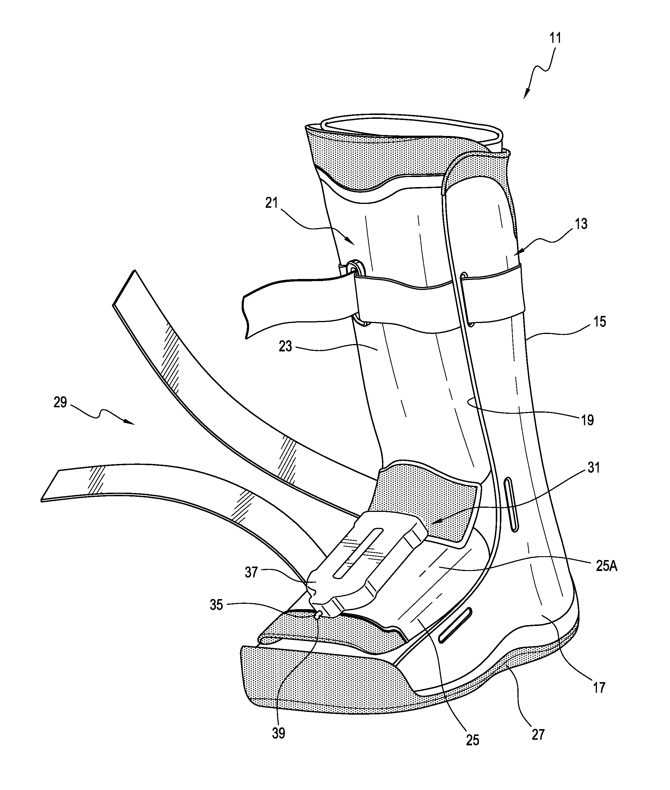
FIG. 1 shows a first embodiment of the NPWT orthopedic device comprising a walker 11 and a NPWT system 31 integrated into the walker 11. The walker 11 includes a base shell 13 and a dorsal shell 21. The base shell 13 includes a posterior portion 15 and a plantar portion 17 arranged to extend along the plantar surface of a user's foot. The base shell 21 defines an opening 19 over a dorsal aspect thereof.
The dorsal shell 21 is contoured to generally correspond to the opening 19 of the base shell 13, such that the lower leg of the user is generally fully enclosed and supported by the walker 11. The dorsal shell 21 is moveable away and towards the base shell 13 in order to open and close the walker 11. The dorsal shell 21 includes a proximal section 23 and a distal section 25.
An insole can be situated in a foot bed of the walker 11. As seen, an outsole 27 can be provided along the plantar portion 17 of the base shell 13. A plurality of tightening mechanisms 29 are arranged to bring the base shell 13 and the dorsal shell 21 closer together for tightening the walker 11 around the lower leg, ankle, and foot. The tightening mechanism 29 can include an ankle strap, an upper strap, and a foot strap. While a circumferential walker is shown, it will be appreciated that other walkers (e.g., a strut walker) may utilize similar configurations.
The NPWT system 31 includes a pump mechanism 37 secured to an upper surface 25A of the distal section 25 of the dorsal shell 21 and a wound covering (see e.g., wound covering 101 shown in FIG. 4) situated inside of the base shell 13 and arranged to form a sealed volume over a wound area of the user. The wound covering is fluidly connected to the pump mechanism 37 via a conduit 35. A tube hole 39 can be formed in the distal member 25 of the dorsal shell 21 for receiving the conduit 35 extending from the pump mechanism 37. The shape of the tube hole 39 can be generally complementary to the shape of the conduit 35. The conduit 35 extending from the pump mechanism 37 is threaded from the exterior of the walker 11 through the tube hole 39. From the tube hole 39, the conduit 35 is guided or routed within the interior of the walker 11 to the wound covering.
The pump mechanism 37 includes a negative pressure source and is arranged to apply a negative pressure to the wound area under the wound covering through the conduit 35. The negative pressure generated by the pump mechanism 37 over the wound area can draw wound exudate and/or other secretions away from the wound area through the conduit 35 into a collection unit, helping to accelerate healing. To help maintain the negative pressure over time, the wound covering may include an adhesive that forms a fluidly tight seal with the skin surrounding the wound area.
As seen, the pump mechanism 37 of the NPWT system 31 can be generally centered over the user's foot on the distal section 25 of the dorsal shell 21 and dimensioned not to increase a width of either the medial or lateral aspects of the walker 11. This is advantageous because additional width on the medial aspect of a walker can result in injuries to the user's contralateral limb, or can result in knee or hip issues from user's avoiding contact with the contralateral limb during gait. Furthermore, adding additional width on the lateral aspect of a walker can be cumbersome for users when they are resting in their side.
The pump mechanism 37 is also generally stacked or centered over a midline of the foot, decreasing the perceived added weight from the pump mechanism 37. The location of the pump mechanism over the foot also reduces moments on the foot about the ankle from the pump mechanism 37, making it easier for users with low muscle tone to lift the foot within the walker 11 during gait, for example, when climbing stairs of walking up a ramp.
By arranging the pump mechanism 37 on the distal section 25 of the dorsal shell 21, the distance between the pump mechanism 37 and the wound area is generally constant and shortened as compared to an external vacuum source being carried near the hip or on other parts of the user's body as in the prior art, reducing the likelihood of the conduit 35 being tangled or caught during use.
This also reduces and stabilizes the effects of fluid head height within the NPWT system 31 that can compete against the negative pressure applied to the wound area by the pump mechanism 37. This is advantageous as NPWT is typically delivered at relative low vacuum pressures such as, for example, between about -75 and -150 mmHg. The vacuum source of known NPWT systems is commonly positioned at or near the waist of a user, which can be roughly 29 inches above a wound area on the plantar aspect of the foot. This height difference or fluid head height in the NPWT system, if not accounted for, can yield a vacuum reduction of about 55 mmHg, effectively reducing a vacuum of -75 mmHg to about -20 mmHg. It will be appreciated that a vacuum of less than -40 mmHg is known to be less effective in providing healing.
Furthermore, fluid head height created by a vacuum source that is carried at or near the waist can vary with movement of the foot or lower leg relative to waist, which, in turn, can drastically or detrimentally impact negative pressure applied to the wound area, reducing the effectiveness and reliability of the NPWT system. Embodiments of the NPWT system thus beneficially position the pump mechanism 37 near the wound area, reducing and stabilizing potentially counterproductive fluid head height within the NPWT system 31.
Placing the pump mechanism 37 on the upper surface of the dorsal shell 21 also improves the accessibility of the NPWT system 31, as it allows the pump mechanism 37 to be easily and readily monitored by patients who are responsible for providing or assisting with their own care. The NPWT system 31 is thus more effective and easier to use for a user than known NPWT systems.
It will be appreciated that the NPWT system 31 can be disposable and can comprise any suitable system. For instance, the pump mechanism 37 and/or the wound dressing can be arranged for single use and can be easily exchanged with replacement components. The pump mechanism 37 can be a vacuum pump, a powered negative pressure source, a manually powered negative pressure source, a suction bulb, and/or any other suitable type of negative pressure source. The pump mechanism 37 can comprise an electro-mechanical pump mechanism. The pump mechanism 37 can be independently operable such that it can create and/or maintain a vacuum during periods of low or no activity for patients who are notoriously non-compliant to therapy protocols.
In an embodiment, the conduit 35 has a flattened configuration, helping to limit or prevent pressure points or lines associated within the conduit 35 pressing against the user's skin or foot within the walker 11. The conduit 35 can include one or more tubes. According to a variation, a collection unit can be integrated with the pump mechanism 37. The collection unit may be located along a length of the conduit 35 before the pump mechanism 37, or may be located elsewhere relative to the pump mechanism 37. In other embodiments, one or more filters and/or valves may be included in the NPWT system 31 to control or limit flow along the vacuum pathway, for example, at an outlet of the pump mechanism 37.
In other embodiments, the collection unit can be a separate, replaceable unit from the pump mechanism 37. This can allow the collection unit to be accessible such that it can be more easily monitored and/or replaced. For instance, the collection unit can be located on the interior of the walker 11 and can be inserted and/or removed through an opening formed in the dorsal shell 21, allowing the collection unit to be removed without removing the dorsal shell 21. This may be particularly advantageous for patients who cannot remove the dorsal shell because of a compliance strap securing the dorsal shell to the base shell. In other embodiments, the collection unit can be inserted and/or removed from the interior of the walker via an opening formed in the base shell 21.
The wound covering can be a flexible cover including one or more pre-cut apertures or a wound dressing. Optionally, the wound covering can include a wound packing material.
According to a variation, at least one indentation or groove can be formed within the interior surface of the walker 11 for guiding the conduit 35 to the wound covering. The groove can be formed on the dorsal shell 21 and/or the base shell 13 and can exhibit any suitable configuration. Routing the conduit 35 through the groove on the interior of the walker 11 can help reduce or eliminate pressure points on the interior of the walker 11, which can be both uncomfortable as well as a risk for resulting in pressure ulcers. Guiding the conduit 35 in the groove can also protect the conduit 35 from being inadvertently crushed or pinched. The conduit 35 can be uncovered or covered or secured in the groove using adhesive tape, a separate cover component, or any other suitable means. The conduit 35 can be flexible so that the conduit 35 can generally conform to the contour of the walker 11.
Second Embodiment of the NPWT Orthopedic Device
FIG. 2 shows another embodiment of the NPWT orthopedic device comprising a walker 11 and a NPWT system 81 including a pump mechanism 87. The pump mechanism 87 in this embodiment is secured to the outer surface 23A of the proximal section 23 of the dorsal shell 21. A tube hole 41 can be formed in the distal section 25 for receiving a conduit 85 extending from the pump mechanism 87. The conduit 85 extending from the pump mechanism 87 can be threaded from the exterior of the walker 11 through the tube hole 41 and to a wound covering within the walker 11.
As seen the pump mechanism 87 is located on the proximal section 23 at or near a strap extending across the ankle and the user's foot. By placing the pump mechanism 37 on the anterior aspect of the walker 11 just above the foot, the fluid head height within the NPWT system 81 is reduced. In addition, weight distribution of the walker 11 can be improved because the weight of the pump mechanism 87 is supported by the lower leg of the user rather than on the foot. This is beneficial because the pump mechanism 87 does not generate a moment on the foot about the ankle, reducing the likelihood of user fatigue due to the incorporation of the NPWT system 81.
Third Embodiment of the NPWT Orthopedic Device
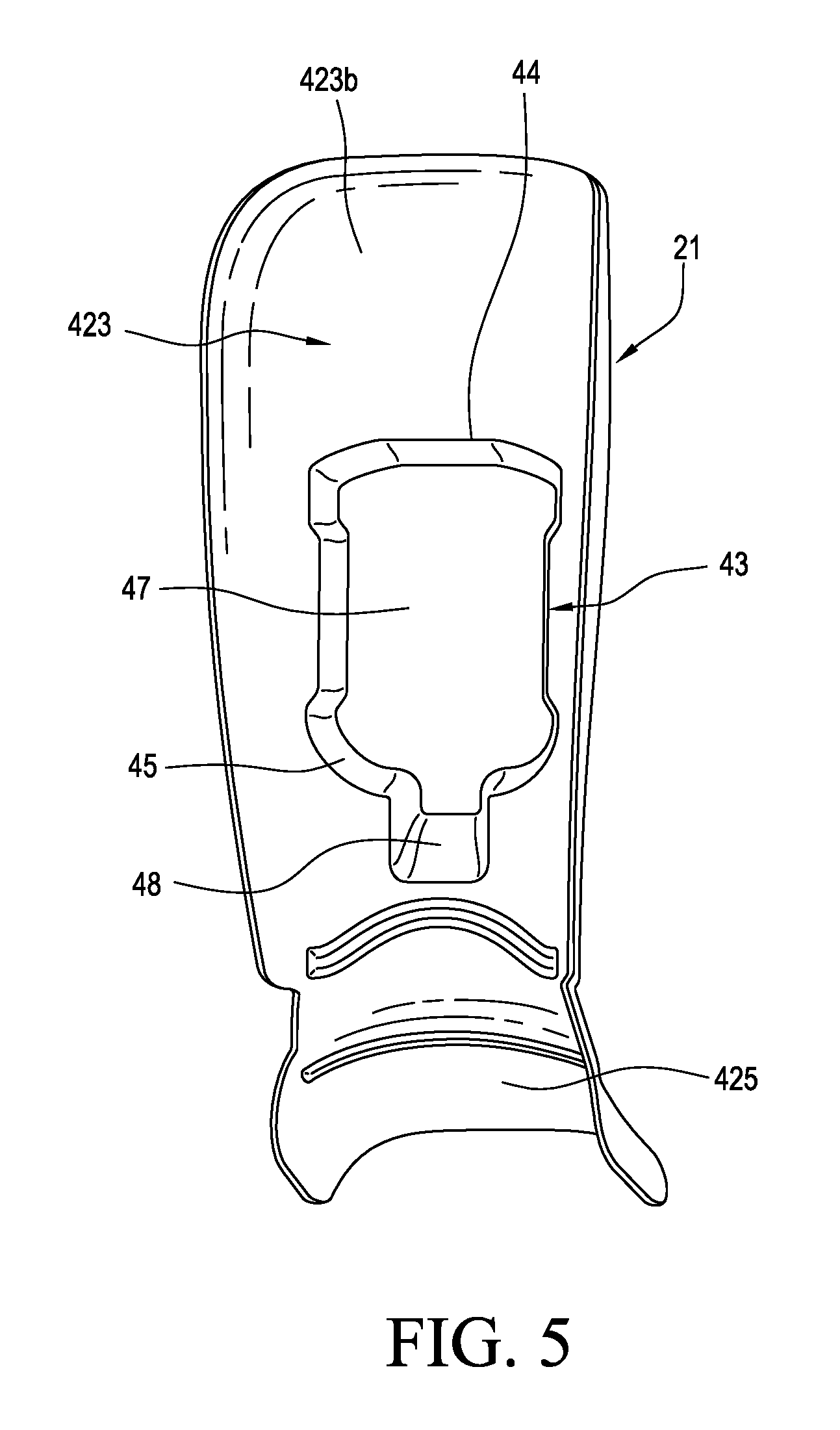
FIGS. 3-5 show another embodiment of the NPWT orthopedic device comprising a walker 11 and a NPWT system 91 including a pump mechanism 97 positioned in a receiving space 43 on a dorsal shell 421. FIGS. 3-5 do not show the tightening members or straps for ease of reference. The dorsal shell 421 includes a proximal section 423 and a distal section 425.
The receiving space 43 is defined along an inner surface 423B of the proximal section 423 over the lower leg of the user. The receiving space 43 can be defined along a length of the proximal section 423 arranged to be between an upper strap member and an ankle strap member arranged to extend over the ankle of the user. The receiving space 43 can be defined along a length of the proximal section 423 below the upper strap member.
The receiving space 43 is sized and configured to house the pump mechanism 97. As seen, the receiving space 43 extends outwardly from the inner surface 423B of the proximal section 423 so that the pump mechanism 97 can fit within the receiving space 43 without substantially impact the space within the walker 11.
Similar to the previously described embodiments, the location of the pump mechanism 97 on the proximal section 423 reduces and stabilizes the effects of fluid head height within the NPWT system 91 by shortening and keeping the distance between the pump mechanism 97 and a wound area generally constant. It also does not increase a width of the medial or lateral aspects of the walker 11, reducing the likelihood of discomfort or injuries to the user due to the pump mechanism 97. The location of the pump mechanism 97 can also decrease the perceived weight of the pump mechanism 97 and reduce or eliminate moments on the foot from the pump mechanism 97 about the user's ankle.
By arranging the pump mechanism 97 within the receiving space 43, the pump mechanism 97 is located inside the walker 11 during use and protected from damage due to accidental contact with external objects. This also reduces the likelihood of tampering or unintended inference with the pump mechanism 97.
Arranging the pump mechanism 97 within the receiving space 43 also beneficially allows the walker 11 to be removed from the foot without having to disconnect the NPWT system 91. For example, as shown in FIG. 4, the NPWT system 91 includes the pump mechanism 97 removably secured in the receiving space 43 and a wound covering 101 situated inside of the base shell 13 on a soft goods liner 99. The liner 99 has foam padding and provides as an interface between the user's anatomy and the walker 11.
The wound covering 101 is fluidly connected to the pump mechanism 97 via a conduit 95 comprising a tube having a flattened configuration. A portion of the tube 95 extending from the pump mechanism 97 is threaded through a first opening 103 in the ankle area of the liner 99 and routed through a thickness of the liner 99 toward the wound covering 101 where the tube 95 exits from the liner 99 from a second opening 104. As such, the user's foot can be removed from the walker 11 without disconnecting the NPWT system 91. In addition, the liner 99 can be easily removed from the walker 11 with the NPWT system 91 intact, making the system more usable. Optionally, the tube 95 can be removably attached to the wound covering 101 and/or the pump mechanism 97 such that the wound covering 101 and/or pump mechanism 97 can be removed or cleaned without having to remove the tube 95 from the liner 99.
Referring to FIG. 5, the receiving space 43 is integral to the proximal section 423. The proximal section 423 includes an access or pump opening 44 and a peripheral sidewall 45 extending from the access opening 44 to a distance beyond the outer surface of the proximal section 423. A closed bottom 47 extends between the peripheral sidewall 45 above the outer surface of the proximal section 423. The receiving space 43 is bounded by the peripheral sidewall 45 and the closed bottom 47. The peripheral sidewall 45 can be continuous or non-continuous.
The receiving space 43 can be sized and shaped such that an interference fit is created between the pump mechanism 97 and the receiving space 43. In other embodiments, the pump mechanism 37 can be secured within the receiving space 43 by adhesives, snaps, fasteners, hook-and-loop type systems, or any other suitable connection systems.
Optionally, a distal portion of the peripheral sidewall 45 can include a ramped surface 48 adapted to help guide the conduit 95 extending from the pump mechanism 37 toward the wound covering 101 as the conduit exits the pump mechanism 37.
Fourth Embodiment of the NPWT Orthopedic Device
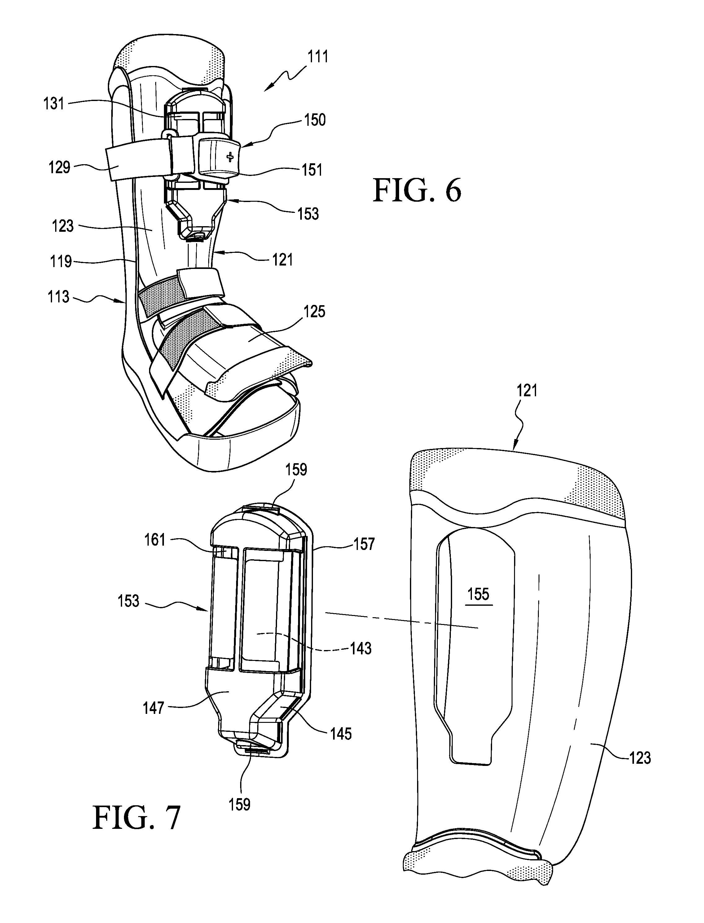
FIGS. 6 and 7 show another embodiment of the NPWT orthopedic device comprising a walker 111 and a NPWT system 131. The walker 111 includes a base shell 113 defining an opening 119 over a dorsal aspect thereof and a dorsal shell 121. The dorsal shell 121 includes a proximal section 123 and a distal section 125 and is contoured to generally correspond to the opening 119 of the base shell 113. A plurality of straps 129 are arranged to bring the base shell 113 and the dorsal shell 121 closer together for tightening the walker 111 around the lower leg, ankle, and foot.
Optionally, the walker 111 can include an inflation system 150 arranged to reduce pressure points within the walker 111, accommodate different sized anatomies, and/or to accommodate swelling. The inflation system 150 includes a pump assembly 151 situated on the upper strap 129 and arranged to inflate at least one inflatable bladder disposed in the base shell 113.
A receiving space 143 on the dorsal shell 121 is arranged to house a pump mechanism of the NPWT system 131. The receiving space 143 can be similar to the receiving space 43 except that it is at least part defined by a cover member 153 removably attached to the proximal section 123.
As seen in FIG. 7, a cutout 155 is defined in the proximal section 123. The cover member 153 is sized and configured to engage the cutout 155 and includes a peripheral sidewall 145 extending from the cutout 155 to a distance beyond the outer surface of the proximal section 123. The cover member 153 includes a closed bottom 147 that extends between the peripheral sidewall 145 above the outer surface of the proximal section 123. The closed bottom 147 can define one or more observation holes 161, allowing for visual observation of the pump mechanism within the receiving space 143. The receiving space 143 is bounded by the peripheral sidewall 145 and the closed bottom 147 of the cover member 153.
The cover member 153 can be attached to the proximal section 123 over the cutout 155 in any suitable manner. The cover member 153 can be secured to the proximal section 123 via a snap-type connection. The cover member 153 can be secured to the proximal section 123 via a peripheral flange 157 arranged to engage the inner surface of the proximal section 123 and upper and lower protrusions 159 arranged to engage the outer surface of the proximal section 123 opposite the flange 157.
The cover member 153 can be detached from the outside of the walker 111, providing access to the pump mechanism from the outside of the walker 111. This beneficially allows the pump mechanism to be removed, replaced, and/or maintained without having to remove the walker 111 from the user's leg.
Optionally, the upper strap 129 can be arranged to extend over the closed bottom 147 of the cover member 153 to help secure the cover member 153 on the proximal section 123 over the cutout 155. Alternatively, the cover member 153 can be removably attached to the proximal section 123 via fasteners, hook-and-loop type systems, clips, magnets, or any other suitable attachment system.
By arranging the pump mechanism within the cutout 155 and the cover member 153, the pump mechanism can be protected from damage due to accidental contact with external objects. Moreover, the cover member 153 can help limit or eliminate pressure points from pump mechanism.
Fifth Embodiment of the NPWT Orthopedic Device
FIGS. 8 and 9 show another embodiment of the NPWT orthopedic device comprising a walker 211 and a NPWT system 231 including a pump mechanism 49 located along the posterior aspect of the base shell 213. The dorsal shell, liner, straps, and insole are removed from the walker 211 for ease of reference.
The pump mechanism 49 is located on the posterior aspect of the base shell 213 about halfway up a height of the walker 211. By arranging the pump mechanism 49 on the posterior aspect of the base shell 213, the pump mechanism 49 does not interfere with dorsal shell placement or from accessing the straps. In addition, the location of the pump mechanism 49 reduces and stabilizes the effects of fluid head height within the NPWT system 231 by shortening and keeping the distance between the pump mechanism 49 and the wound area generally constant. It also does not increase a width of the medial or lateral aspects of the walker 211, reducing the likelihood of discomfort or injuries to the user due to the pump mechanism 49.
As seen, a top surface of the pump mechanism 49 is spaced a distance from the proximal edge of the base shell 213 forming a clearance between the pump mechanism 49 and the proximal edge such that the pump mechanism 49 does not interfere with the posterior thigh during flexion.
The pump mechanism 49 is secured to the base shell 213 via a clip member 51 formed on the pump mechanism 49. The clip member 51 includes a proximal end section 55 and a distal section 57. The proximal end section 55 is attached to the pump mechanism 49 and the distal section 57 includes a free end. The distal section 57 is formed so as to bias the clip member 51 toward the outer surface of the pump mechanism 49. In other embodiments, the pump mechanism 49 can be secured to the posterior portion 215 via a cover member, a hook-and-loop type system or the like.
A cutout 53 is formed in the posterior portion 215 that extends completely between the interior and exterior surfaces of the base shell 13. The cutout 53 can have any suitable configuration. The clip member 51 can be inserted through the cutout 53 such that the posterior portion 215 of the base shell 213 can be secured between the inner surface of the clip member 51 and the outer surface of the pump mechanism 49. Through the structure of the clip member 51 and the pump mechanism 49, the pump mechanism 49 has the benefit of being easily and quickly removed from the base shell 13. According to a variation, the cutout 53 can provide at least in part a housing for other components of the walker 211 (e.g., air system valves).
A conduit 235 extends downwardly from the distal end section of the pump mechanism 49 along the exterior surface of the posterior portion 215, reducing the likelihood of a pressure point from the conduit 235 as the patient walks in the walker 211 and the likelihood of the conduit 235 being pinched or kinked inside of the walker 211.
The posterior portion 215 of the base shell 213 includes a tube hole 61 that allows the conduit 235 to pass from the exterior surface of the posterior portion 215 to the interior surface of the base shell 213 such that the conduit 235 can connect to a wound covering 233 within the walker 211.
At least one indentation or groove 51 can be formed within the interior surface of the base shell 213 for guiding the conduit to the cover 233. The groove 51 can be any suitable configuration. For instance, the groove 51 can extend from the tube hole 61 to a point below the upper surface of the cover 233. Routing the conduit 235 through the groove 51 on the interior of the base shell 213 can help reduce or eliminate pressure points on the interior of the walker 211, which can be both uncomfortable as well as a risk for resulting in pressure ulcers. Guiding the conduit 235 in the groove 51 can also protect the conduit 235 from being inadvertently crushed or pinched. The conduit 235 can be uncovered or covered or secured in the groove 51 using adhesive tape, a separate cover component, or any other suitable means.
In other embodiments, the pump mechanism 49 can be located within a receiving space formed on the interior surface of the posterior portion 215 of the base shell 213. In other embodiments, the pump mechanism 49 can be positioned under a cover member attached to the posterior portion 215 of the base shell 213, protecting the pump mechanism for inadvertent damage or tampering.
Sixth Embodiment of the NPWT Orthopedic Device
FIG. 10 shows another embodiment of the NPWT Orthopedic Device comprising a walker 311 and a NPWT system 331 having a pump mechanism 63 located along the posterior aspect of the base shell 313 and attached to the posterior portion 315 via an attachment system 65 that allows the pump mechanism 63 to be removably attached to the base shell 313.
The attachment system 65 can include a clip 67 having a first arm 69, a second arm 71, and a base 73. The first and second arms 69 and 71 each define an engagement surface and are spaced at a distance less than the diameter of an outer surface of body of the pump mechanism 63. The engagement surfaces can form a shape that generally complements the shape of the body of the pump mechanism 63. Each arm 69, 71 further includes a retaining section 75 that protrudes from a free end of its engagement surface. At least one of the retaining sections 75 protrudes toward the opposite engagement surface, thereby narrowing the distance between the engagement surfaces.
The base 73 connect the ends of the arms opposite the retaining sections 75, and holds these ends in a substantially rigid position with respect to each other, such that the engagement surfaces of the clip 67 will resiliently engage the pump mechanism 63 when the arms 69, 71 are received over the body of the pump mechanism 63. The retaining sections 75 narrow the opening between the free ends of the arms, and are arranged to prevent unforced radial removal of the pump mechanism 63 from the clip 67.
The conduit 335 can extend downwardly from the distal end section of the pump mechanism 63 to a tube hole 78 formed at or near the plantar portion 317 of the base shell 313. The tube hole 78 can extend through the outsole 327 and allows the conduit 335 to pass from the exterior surface of the posterior portion 315 to the interior surface of the walker 311 such that the conduit 335 can connect to the wound covering within the walker.
As noted above, the NPWT system can be any suitable system. For instance, the pump mechanism 63 shown in FIG. 10 can include a body 79 and a plunger or push rod assembly 81 that extends within and is movable relative to the body 79. The body 79 can include a cylindrical barrel 85 and a nozzle 87. The nozzle 87 can include a port, providing a means of connection such as a luer fitting or other fluid connector.
A conduit 335 can be removably coupled to the nozzle 87 and a valve or filter creating a fluid connection between the barrel 85 and a wound covering. The valve can seal the conduit 335 when the pump mechanism 63 is removed from the conduit 335, reducing the likelihood of contamination or infection.
The plunger assembly 81 can include a plunger head 89 and a plunger rod 91 that extends from the plunger head 89. The plunger rod 91 can extend beyond an end of the body 79. The end of the plunger rod 91 that extends beyond the body 79 may include an appropriate actuation feature for engagement by a patient or another person such that the patient or someone else can manually actuate the pump mechanism 63.
One or more sealing surfaces may be formed on the perimeter of the plunger head 89 that engage the interior wall of the barrel 85. The interface between the perimeter of the plunger head 89 and the interior wall of the barrel 85 defines at least one seal between the plunger head 89 and the barrel 85. A fluid chamber 93 is defined between the bottom surface of the plunger head 89 and the nozzle 87.
When the plunger assembly 81 is moved away from the nozzle 87, the volume of the fluid chamber 93 increases, which, in turn, creates a vacuum or negative pressure inside of the fluid chamber 93. This negative pressure can draw exudate or other fluid into the fluid chamber 93 through the conduit 335 and from the vacuum reservoir formed over the wound by the wound covering. As seen, the barrel 85 can be generally translucent, allowing for observation of fluid in the fluid chamber 93. In other embodiments, the barrel 85 can include a translucent window for observation of fluid in the fluid chamber 93.
With the exudate in the fluid chamber 93, the pump mechanism 63 can be decoupled from the conduit 335 and removed from the attachment system 65 for disposal. Optionally, the plunger assembly 81 of the decoupled pump mechanism 63 can be moved toward the nozzle 87, reducing the volume of the fluid chamber 93 such that fluid within the fluid chamber 93 is discharged or expelled out of the nozzle 87 for disposal or sampling.
A resilient member or internal compression spring 95 can be situated in the fluid chamber 93. The spring 95 can apply a force or pressure to the plunger head 89 in a direction away from the nozzle 87, creating a vacuum in the fluid chamber 93. The amount of vacuum created by the spring 95 can be adjusted or selected by controlling the force provided by the spring 95 on the plunger head 89 over the cross-sectional area of the barrel 85. The spring 95 can be a constant force spring. The spring 95 can be a low-force compression spring.
The pump mechanism 63 is shown including a single barrel and plunger assembly but can also include two or more barrels and plunger assemblies, decreasing the overall length of the pump mechanism 63 required to generate a specific fluid collection volume. The pump mechanism 63 can further include two barrels, each including a spring or a coupler to connect each of the barrels to a common spring. This can help create consistency of vacuum pressure between the barrels. Further, the body 79 is described including a single port but may include any number of ports. For instance, the body 79 may include an inlet port and an outlet port, each associated with a one-way valve to control the direction of fluid flow. The inlet one-way valve only allows fluid to enter the fluid chamber 93 and is connected to the conduit 335. The outlet one-way valve only allows fluid to be expelled out of the fluid chamber 93.
While one conduit is described, it will be appreciated that the NPWT system of present disclosure can include two, three, or any other suitable number of conduits. In other embodiments, the conduit can comprise channels formed within the walls of the walker that provide fluid communication between the pump mechanism and the cover. In yet other embodiments, the NPWT system can include two, three, or any other suitable number of pump mechanisms. In other embodiments, a collection unit can be incorporated into the structure of the walker. In other embodiments, the pump mechanism can be attached to the anterior or posterior aspect of the tightening members or straps 29.
While various aspects and embodiments have been disclosed herein, other aspects and embodiments are contemplated. The various aspects and embodiments disclosed herein are for purposes of illustration and are not intended to be limiting. Additionally, the words "including," "having," and variants thereof (e.g., "includes" and "has") as used herein, including the claims, shall be open ended and have the same meaning as the word "comprising" and variants thereof (e.g., "comprise" and "comprises").
* * * * *
References
-
djortho.com
-
aircast.com/index.asp/fuseaction/products.detail/cat/2/id/104
-
-
-
-
D00000
D00001
D00002
D00003
D00004
D00005
D00006
D00007
D00008
XML
uspto.report is an independent third-party trademark research tool that is not affiliated, endorsed, or sponsored by the United States Patent and Trademark Office (USPTO) or any other governmental organization. The information provided by uspto.report is based on publicly available data at the time of writing and is intended for informational purposes only.
While we strive to provide accurate and up-to-date information, we do not guarantee the accuracy, completeness, reliability, or suitability of the information displayed on this site. The use of this site is at your own risk. Any reliance you place on such information is therefore strictly at your own risk.
All official trademark data, including owner information, should be verified by visiting the official USPTO website at www.uspto.gov. This site is not intended to replace professional legal advice and should not be used as a substitute for consulting with a legal professional who is knowledgeable about trademark law.