Fluid machine
Kim A
U.S. patent number 10,385,877 [Application Number 15/421,845] was granted by the patent office on 2019-08-20 for fluid machine. This patent grant is currently assigned to HANWHA POWER SYSTEMS CO., LTD. The grantee listed for this patent is HANWHA POWER SYSTEMS CO., LTD.. Invention is credited to Kil Young Kim.


| United States Patent | 10,385,877 |
| Kim | August 20, 2019 |
Fluid machine
Abstract
A fluid machine includes a rotatable hub; a plurality of blades spaced apart from one another along a circumferential direction with respect to a rotation center of the hub; and a shroud extending along a circumferential direction with respect to the rotation center of the hub and covering the plurality of blades. The shroud includes: a flow passage, the flow passage formed to be recessed with respect to an inner surface of the shroud facing the blades; and a plurality of resonators provided in the flow passage.
| Inventors: | Kim; Kil Young (Changwon-si, KR) | ||||||||||
|---|---|---|---|---|---|---|---|---|---|---|---|
| Applicant: |
|
||||||||||
| Assignee: | HANWHA POWER SYSTEMS CO., LTD
(Changwon-si, KR) |
||||||||||
| Family ID: | 59386471 | ||||||||||
| Appl. No.: | 15/421,845 | ||||||||||
| Filed: | February 1, 2017 |
Prior Publication Data
| Document Identifier | Publication Date | |
|---|---|---|
| US 20170218979 A1 | Aug 3, 2017 | |
Foreign Application Priority Data
| Feb 2, 2016 [KR] | 10-2016-0012899 | |||
| Current U.S. Class: | 1/1 |
| Current CPC Class: | F04D 29/665 (20130101); F04D 17/10 (20130101); F04D 29/284 (20130101); F04D 29/526 (20130101); F04D 29/685 (20130101); F04D 29/4213 (20130101); Y10S 415/914 (20130101) |
| Current International Class: | F04D 29/66 (20060101); F04D 29/68 (20060101); F04D 29/52 (20060101); F04D 29/28 (20060101); F04D 17/10 (20060101); F04D 29/42 (20060101) |
References Cited [Referenced By]
U.S. Patent Documents
| 4212585 | July 1980 | Swarden |
| 4540335 | September 1985 | Yamaguchi et al. |
| 4743161 | May 1988 | Fisher |
| 5256031 | October 1993 | Bothien et al. |
| 6164911 | December 2000 | LeBlanc |
| 6379110 | April 2002 | McCormick et al. |
| 7658592 | February 2010 | Jarrah |
| 8197188 | June 2012 | Clay |
| 8465251 | June 2013 | Hosoya |
| 8888440 | November 2014 | Tomita |
| 8926276 | January 2015 | Japikse |
| 2002-537184 | Nov 2002 | JP | |||
| 2007-218147 | Aug 2007 | JP | |||
| 1998-060499 | Oct 1998 | KR | |||
Attorney, Agent or Firm: Sighrue Mion, PLLC
Claims
What is claimed is:
1. A fluid machine comprising: a rotatable hub; a plurality of blades spaced apart from one another along a circumferential direction with respect to a rotation center of the hub; and a shroud extending along the circumferential direction with respect to the rotation center of the hub and covering the plurality of blades, the shroud comprising: a flow passage, the flow passage formed to be recessed with respect to an inner surface of the shroud facing the blades; and a plurality of resonators provided in the flow passage, wherein the shroud comprises: an inlet portion configured to guide an inflow of fluid toward the plurality of blades; and an outlet portion configured to guide discharge of the fluid that has passed through the plurality of blades, wherein the plurality of resonators are arranged in the flow passage with a uniform density in an entire area of the flow passage from the inlet portion of the shroud to the outlet portion.
2. The fluid machine of claim 1, wherein each of the plurality of resonators comprises: an opening portion provided on a surface of the flow passage facing the plurality of blades; and a space portion connected to the opening portion and extending radially from the opening portion, the space portion forming a hollow space in the shroud.
3. The fluid machine of claim 1 further comprising a base arranged around the hub, extending along a circumferential direction with respect to the rotation center of the hub and supporting the plurality of blades.
4. The fluid machine of claim 1, wherein the flow passage extends from the inlet portion toward the outlet portion and is formed in at least a partial section of the inner surface of the shroud.
5. A fluid machine comprising: a rotatable hub; a plurality of blades spaced apart from one another along a circumferential direction with respect to a rotation center of the hub; and a shroud extending along the circumferential direction with respect to the rotation center of the hub and covering the plurality of blades, the shroud comprising: a flow passage, the flow passage formed to be recessed with respect to an inner surface of the shroud facing the blades; and a plurality of resonators provided in the flow passage, wherein the shroud comprises: an inlet portion configured to guide an inflow of fluid toward the plurality of blades; and an outlet portion configured to guide discharge of the fluid that has passed through the plurality of blades, and wherein a density of the plurality of resonators arranged in the flow passage increases from the inlet portion of the shroud toward the outlet portion.
6. The fluid machine of claim 5, wherein the plurality of resonators are arranged only in a partial area of an entire area of the flow passage.
7. A fluid machine comprising: a rotatable hub; a plurality of blades spaced apart from one another along a circumferential direction with respect to a rotation center of the hub; and a shroud extending along the circumferential direction with respect to the rotation center of the hub and covering the plurality of blades, the shroud comprising: a flow passage, the flow passage formed to be recessed with respect to an inner surface of the shroud facing the blades; and a plurality of resonators provided in the flow passage, wherein the shroud comprises: an inlet portion configured to guide an inflow of fluid toward the plurality of blades; and an outlet portion configured to guide discharge of the fluid that has passed through the plurality of blades, wherein the plurality of resonators are arranged only in a partial area of an entire area of the flow passage, and wherein the plurality of resonators are arranged in an area of the flow passage located at a distance from the inlet portion of the shroud determined by a preset distance from the inlet portion of the shroud toward the outlet portion.
8. A fluid machine comprising: a rotatable hub; a plurality of blades spaced apart from one another along a circumferential direction with respect to a rotation center of the hub; and a shroud extending along the circumferential direction with respect to the rotation center of the hub and covering the plurality of blades, the shroud comprising: a flow passage, the flow passage formed to be recessed with respect to an inner surface of the shroud facing the blades; and a plurality of resonators provided in the flow passage, wherein each of the plurality of resonators comprises: an opening portion provided on a surface of the flow passage facing the plurality of blades; and a space portion connected to the opening portion and extending radially from the opening portion, the space portion forming a hollow space in the shroud, and wherein the shroud comprises: a first plate arranged at a position contacting the plurality of blades and comprising the flow passage and the opening portion of each of the plurality of resonators; and a second plate provided on the first plate and comprising the space portion of each of the plurality of resonators at a position corresponding to the opening portion of each of the plurality of resonators.
9. A fluid machine comprising: a rotatable hub; a base connected to the hub and extending radially from the hub; a plurality of blades provided on the base and spaced apart from one another along a circumferential direction with respect to a rotation center of the hub; and a shroud extending along the circumferential direction with respect to the rotation center of the hub and covering the plurality of blades, the shroud comprising: an inner surface facing the base and contacting the plurality of blades; a flow passage formed to be recessed with respect to the inner surface of the shroud facing the base; and a plurality of resonators provided in the flow passage.
10. The fluid machine of claim 9, wherein the shroud comprises: an inlet portion configured to guide an inflow of fluid toward the plurality of blades; and an outlet portion configured to guide discharge of the fluid that has passed through the plurality of blades.
11. The fluid machine of claim 9, wherein the flow passage comprises: a first region in which the plurality of resonators are arranged; and a second region in which none of the plurality of resonators are provided in the flow passage.
Description
CROSS-REFERENCE TO RELATED APPLICATION
This application claims priority from Korean Patent Application No. 10-2016-0012899, filed on Feb. 2, 2016, in the Korean Intellectual Property Office, the disclosure of which is incorporated herein in its entirety by reference.
BACKGROUND
1. Field
Apparatuses consistent with exemplary embodiments relate to a fluid machine, and more particularly, to a fluid machine having improved aerodynamics performance and reduced noise generation.
2. Description of the Related Art
Compressors, expanders, or pumps, which compress or expand fluid, have a fluid machine using a rotation element. A fluid machine has an impeller as a rotation element. The impeller transfers rotational dynamic energy to fluid thereby increasing the pressure of fluid. The impeller includes a plurality of blades that guide movement of fluid and transfer energy to the fluid.
A shroud is arranged outside the impeller, and the shroud forms a passage for passing fluid together with the blades. In order to design a fluid machine having superior performance, aerodynamics performance in the passage formed by the impeller and the shroud needs to be enhanced.
However, during an operation of the impeller, high pressure is generated by the fluid such that loud noise is generated between the impeller and the shroud. There have been many trials to reduce noise from operation of the impeller. However, when a separate apparatus is installed on the impeller or the shroud to reduce noise, aerodynamic loss is generated in the fluid machine.
Accordingly, there is a demand for technology to be developed for reducing noise and simultaneously maintaining superior aerodynamics performance in the passage between the impeller and the shroud for passing fluid in the design of a fluid machine.
U.S. Pat. No. 5,256,031 discloses that a groove is formed on a casing wall to reduce vibration. However, a groove-forming technology such as this seriously increases aerodynamic loss.
Japanese Publication No. 2007-218147 discloses technology by which a hole is formed in a shroud to reduce noise. As such, a simple structure in which a hole is formed in a wall of the shroud seriously increases aerodynamic loss.
Japanese Publication No. 2002-537184, Korean Publication No. 1998-0060499, and U.S. Pat. No. 4,540,335 disclose technologies using a hole to improve noise or improve flow rate properties. In these technologies, however, because a structure is used in which a hole is formed at a position of a casing corresponding to a tip (end portion) of a rotating blade, it is difficult to apply the structure to improve aerodynamics performance and reduce noise in a fluid machine using a shroud covering an upper surface of a rotating blade.
SUMMARY
One or more exemplary embodiments provide a fluid machine having reduced noise generation by arranging resonators on a shroud.
One or more exemplary embodiments also provide a fluid machine having resonators for reducing noise and simultaneously having improved aerodynamics performance.
Additional aspects will be set forth in part in the description which follows and, in part, will be apparent from the description, or may be learned by practice of the presented exemplary embodiments.
According to an aspect of an exemplary embodiment, a fluid machine may include a rotatable hub, a plurality of blades arranged around the hub and spaced apart from one another along a circumferential direction with respect to a rotation center of the hub, and a shroud extending along a circumferential direction with respect to the rotation center of the hub and covering the blades, the shroud including a flow passage, the flow passage formed to be concave with respect to an inner surface facing the blades, and a plurality of resonators arranged in the flow passage.
Each of the plurality of resonators may include an opening opened in a surface of the flow passage facing the plurality of blades and a space portion connected to the opening and extending outwardly from the opening, forming a hollow space in the shroud.
The fluid machine may further include a base arranged around the hub, extending along a circumferential direction with respect to the rotation center of the hub and supporting the plurality of blades.
The shroud may include an inlet that guides an inflow of fluid toward the plurality of blades and an outlet that guides discharge of the fluid that has passed through the plurality of blades.
The flow passage may extend from the inlet toward the outlet and may be formed in at least a partial section of the inner surface of the shroud.
The plurality of resonators may be arranged in the flow passage with a uniform density in an entire area of the flow passage from the inlet of the shroud to the outlet.
A density of the plurality of resonators arranged in the flow passage may increase from the inlet of the shroud toward the outlet.
The plurality of resonators may be arranged only in a partial area of an entire area of the flow passage from the inlet of the shroud toward the outlet.
The plurality of resonators may be arranged in an area of the flow passage located at a distance from the inlet of the shroud determined by a preset distance from the inlet of the shroud toward the outlet.
The shroud may include a first plate arranged at a position contacting the plurality of blades and including the flow passage and the opening of each of the plurality of resonators, and a second plate arranged above the first plate and including the space portion of each of the plurality of resonators at a position corresponding to the opening of each of the plurality of resonators.
According to an aspect of another exemplary embodiment, a fluid machine may include a rotatable hub; a plurality of blades spaced apart from one another along a circumferential direction with respect to a rotation center of the hub; and a shroud extending along the circumferential direction with respect to the rotation center of the hub and covering the plurality of blades, the shroud may include: a flow passage, the flow passage formed to be recessed with respect to an inner surface of the shroud facing the blades; and a plurality of resonators provided in the flow passage.
Each of the plurality of resonators may include: an opening portion provided on a surface of the flow passage facing the plurality of blades; and a space portion connected to the opening and extending radially from the opening portion, the space portion forming a hollow space in the shroud.
The fluid machine may further include a base arranged around the hub, extending along a circumferential direction with respect to the rotation center of the hub and supporting the plurality of blades.
The shroud may include: an inlet portion configured to guide an inflow of fluid toward the plurality of blades; and an outlet portion configured to guide discharge of the fluid that has passed through the plurality of blades.
The flow passage may extend from the inlet portion toward the outlet portion and is formed in at least a partial section of the inner surface of the shroud.
The plurality of resonators may be arranged in the flow passage with a uniform density in an entire area of the flow passage from the inlet portion of the shroud to the outlet portion.
A density of the plurality of resonators arranged in the flow passage may increase from the inlet portion of the shroud toward the outlet portion.
The plurality of resonators may be arranged only in a partial area of an entire area of the flow passage.
The plurality of resonators may be arranged in an area of the flow passage located at a distance from the inlet portion of the shroud determined by a preset distance from the inlet portion of the shroud toward the outlet.
The shroud may include: a first plate arranged at a position contacting the plurality of blades and including the flow passage and the opening portion of each of the plurality of resonators; and a second plate provided on the first plate and including the space portion of each of the plurality of resonators at a position corresponding to the opening portion of each of the plurality of resonators.
According to an aspect of another exemplary embodiment, a fluid machine may include: a rotatable hub; a base connected to the hub and extending radially from the hub; a plurality of blades provided on the base and spaced apart from one another along a circumferential direction with respect to a rotation center of the hub; and a shroud extending along the circumferential direction with respect to the rotation center of the hub and covering the plurality of blades, the shroud including: an inner surface facing the base and contacting the plurality of blades; a flow passage formed to be recessed with respect to the inner surface of the shroud facing the base; and a plurality of resonators provided in the flow passage.
The shroud may include: an inlet portion configured to guide an inflow of fluid toward the plurality of blades; and an outlet portion configured to guide discharge of the fluid that has passed through the plurality of blades.
The flow passage may include: a first region in which the plurality of resonators are arranged; and a second region in which none of the plurality of resonators are provided in the flow passage.
BRIEF DESCRIPTION OF THE DRAWINGS
The above and/or other aspects of the disclosure will become apparent and more readily appreciated from the following description of the exemplary embodiments, taken in conjunction with the accompanying drawings in which:
FIG. 1 is a perspective view of a structure of a fluid machine according to an exemplary embodiment, in which constituent elements are disassembled from each other;
FIG. 2 is a perspective view illustrating an assembled state of the fluid machine of FIG. 1;
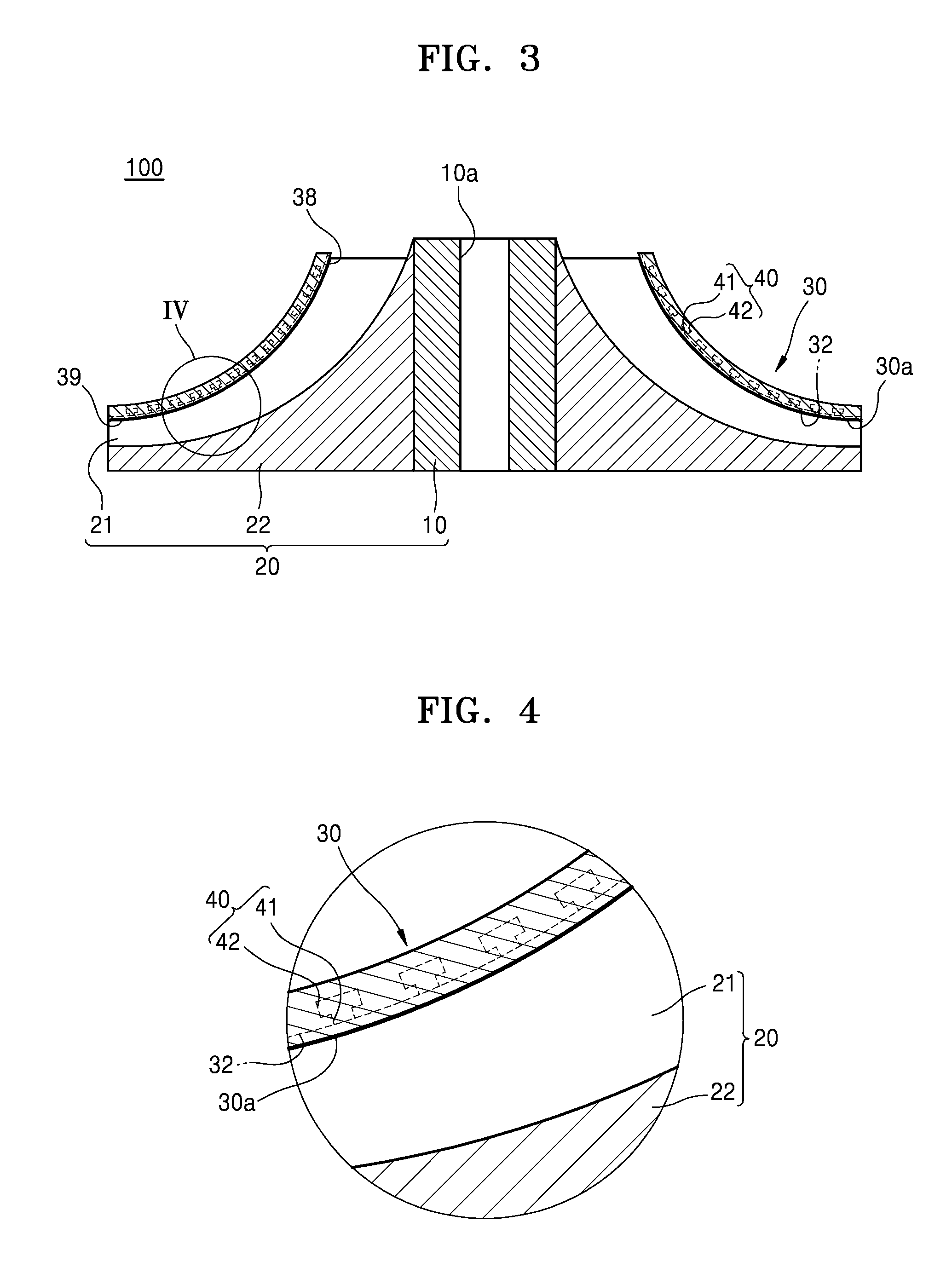
FIG. 3 is a cross-sectional view taken along a line III-III of the fluid machine of FIG. 2;
FIG. 4 is an enlarged cross-sectional view of a portion IV of the fluid machine of FIG. 3;
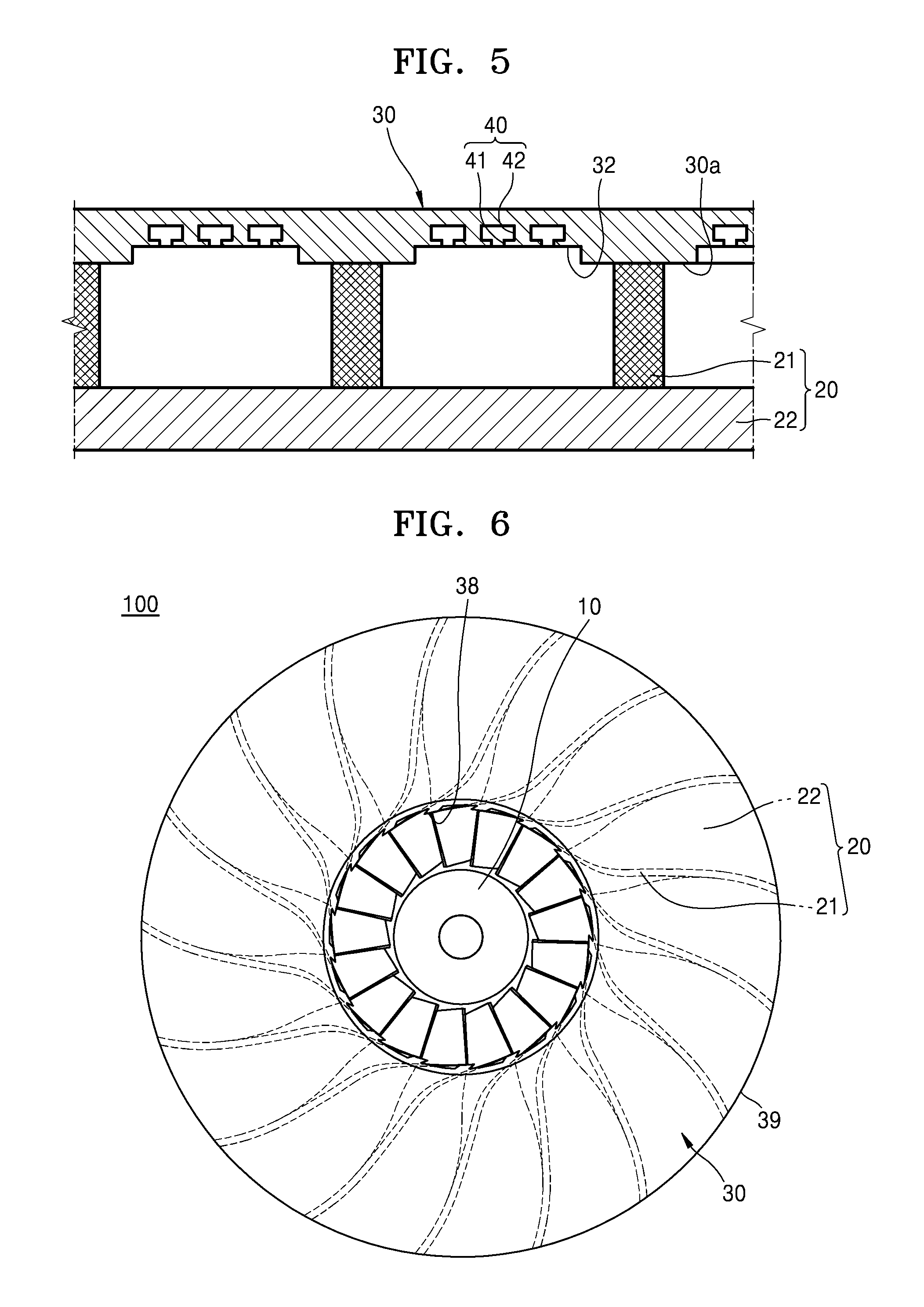
FIG. 5 is a cross-sectional view taken along a line V-V of the fluid machine of FIG. 2;
FIG. 6 is a plan view of the fluid machine of FIG. 2;
FIG. 7 is an enlarged view of a portion of a shroud of the fluid machine of FIG. 1;
FIG. 8 is an enlarged view of a portion of a shroud of a fluid machine according to an exemplary embodiment;
FIG. 9 is an enlarged view of a portion of a shroud of a fluid machine according to an exemplary embodiment;
FIG. 10 is a cross-sectional view of a shroud to illustrate a process of manufacturing the shrouds of the fluid machines of FIGS. 1 to 9;
FIG. 11 is a cross-sectional view of a shroud to illustrate a process of manufacturing the shrouds of the fluid machines of FIGS. 1 to 9;
FIG. 12 is a cross-sectional view of the shroud manufactured by the process of FIG. 11; and
FIG. 13 is an enlarged view of a portion of a shroud of a fluid machine according to an exemplary embodiment.
DETAILED DESCRIPTION
Reference will now be made in detail to exemplary embodiments, examples of which are illustrated in the accompanying drawings, wherein like reference numerals refer to like elements throughout. In this regard, the exemplary embodiments may have different forms and should not be construed as being limited to the descriptions set forth herein. Accordingly, the exemplary embodiments are merely described below, by referring to the figures, to explain aspects of the present description. Expressions such as "at least one of," when preceding a list of elements, modify the entire list of elements and do not modify the individual elements of the list.
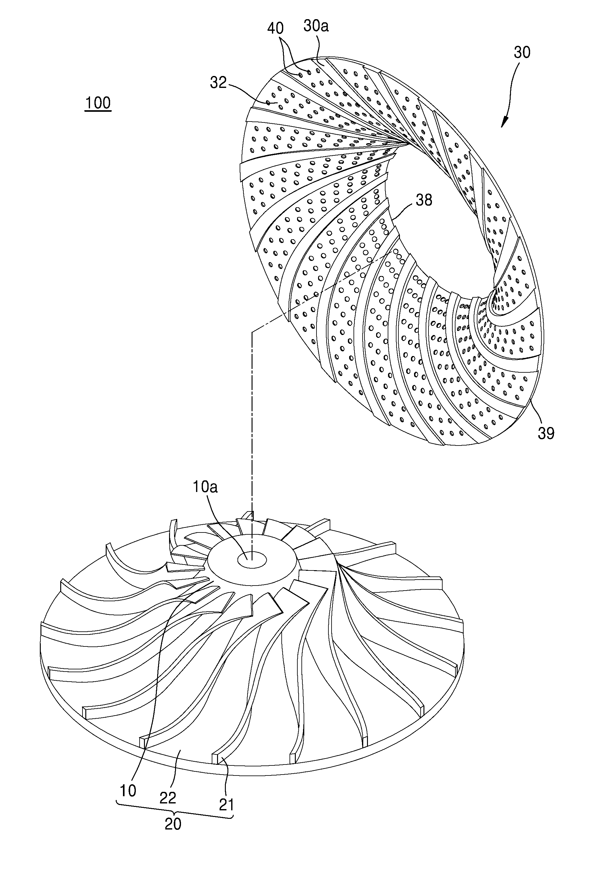
FIG. 1 is a perspective view of a structure of a fluid machine 100 according to an exemplary embodiment, in which constituent elements are disassembled from each other. FIG. 2 is a perspective view illustrating an assembled state of the fluid machine 100 of FIG. 1. FIG. 3 is a cross-sectional view taken along a line III-III of the fluid machine 100 of FIG. 2.
The fluid machine 100 according to the exemplary embodiment illustrated in FIGS. 1 to 3 may include a hub 10, a plurality of blades 21 arranged on and around the hub 10, and a shroud 30 arranged to cover the blades 21.
Although rotating machines are implemented by compressors in the exemplary embodiments illustrated in the drawings, the present disclosure is not limited thereto. In other words, a rotating machine according to an exemplary embodiment may be any apparatus capable of changing the pressure and velocity of fluid by a rotation motion of an impeller. For example, a rotating machine according to the exemplary embodiment may be implemented by an expander (turbine) for expanding fluid, a pump, or a blower.
The hub 10 has a cylindrical shape and has a shaft coupling hole 10a, in which a rotation shaft may be inserted. A base 22 is arranged around the hub 10. Outer diameter of the base 22 increases along a vertical direction of the center of the hub 10 from the top to the bottom of the base 22. The base 22 extends in a circumferential direction with respect to the center of the hub 10.
The base 22 is coupled to an outer surface of the hub 10 and the outer diameter of the base 22 increases along a vertical direction of the center of the hub 10 from the top to the bottom of the base 22. Because a surface of the base 22 is an inclined curved surface, the surface of the base 22 forming a bottom surface of a passage for passing fluid is designed to enable a smooth flow of the fluid and to transfer maximum energy to the fluid.
The blades 21 are arranged around the hub 10 to be spaced apart from one another in a preset interval in a circumferential direction with respect to a rotation center of the hub 10. The blades 21 may be arranged on an upper surface of the base 22 and, as the base 22 is coupled to the outer surface of the hub 10, the blades 21 may be arranged circumferentially around the hub 10. The blades 21 extend outwardly from the hub 10 in the radial direction of the hub 10.
An impeller 20 including the hub 10, the blades 21, and the base 22 guides a flow of fluid while simultaneously transferring dynamic energy of the impeller 20 to the fluid.
The shroud 30 has an inlet 38 for the fluid formed at an open upper end portion thereof and an outlet 39 for the fluid radially and downwardly extending from the inlet 38 at the open upper end portion. The shroud 30 forms a ceiling surface of the passage of the fluid. The shroud 30 forms the passage of the fluid with the base 22 and the blades 21.
Referring to FIG. 3, as a modified example, when a fluid machine 100 is designed to be an expander (turbine), the inlet 38 may be manufactured to function as an outlet, whereas the outlet 39 may be manufactured to function as an inlet.
The inlet 38 of the shroud 30 guides the fluid to be input toward the blades 21. Furthermore, the outlet 39 of the shroud 30 guides the fluid moved by the blades 21 to be discharged to the outside of the shroud 30.
The shroud 30 extends radially from the hub 10 and also extends in a circumferential direction with respect to the rotation center of the hub 10 and is arranged covering upper end portions of the blades 21 as shown in FIG. 2. The shroud 30 and the blades 21 may be fixed to each other, for example, by a welding process or by using a coupling device such as rivets or bolts. When the shroud 30 and the blades 21 are fixed to each other, the hub 10, the blades 21, and the shroud 30 may rotate together.
To maintain a fixed position relative to the hub 10 and the blades 21, for example, the shroud 30 may be fixed on an external structure instead of the blades 21. When the shroud 30 is fixed on the external structure, the shroud 30 maintains the fixed position relative to the hub 10 and the blades 21 during the rotation of the hub 10 and the blades 21, thereby forming part of the passage.
When the impeller 20 performs a rotation motion, the fluid incoming through the inlet 38 of the shroud 30 is discharged to the outside through the outlet 39 of the shroud 30 by a centrifugal force. In other words, the fluid is compressed to a high-pressure state and discharged through the outlet 39 by the centrifugal force according to rotational dynamic energy of the impeller 20. While the fluid passes through a diffuser (not shown), for example, the velocity of the fluid discharged to the outside of the impeller 20 through the outlet 39 decreases and simultaneously the pressure of the fluid increases to a requested level.
The shroud 30 may include a flow passage (or a flow passage surface; hereinafter "a flow passage") 32 formed to be recessed (or sunken) with respect to an inner surface 30a facing the blades 21 as FIG. 1 (and FIG. 4). The flow passage 32 radially extends from the inlet 38 of the shroud 30 toward the outlet 39. The shroud 30 may also include a plurality of resonators 40 arranged in the flow passage 32.
The flow passage 32 formed in the shroud 30 guides a flow of the fluid that is moved and compressed by the rotation motion of the blades 21, thereby enabling the fluid to move smoothly. The flow passage 32 radially extends from the hub 10 toward the outside in a direction in which the blades 21 are formed, and is formed to be curved in the circumferential direction. As such, aerodynamic loss of the fluid passing between the shroud 30 and the blades 21 may be reduced by the structure of the flow passage 32 formed in the shroud 30.
FIG. 4 is an enlarged cross-sectional view of a portion IV of the fluid machine 100 of FIG. 3. FIG. 5 is a cross-sectional view taken along a line V-V of the fluid machine 100 of FIG. 2. FIG. 6 is a plan view of the fluid machine 100 of FIG. 2.
Each of the plurality of resonators 40 may include an opening 41 (or an opening portion) opened in a surface of the flow passage 32 facing the blades 21 and a space portion 42 connected to the opening 41 and extending from the opening 41 to the outside, thereby forming an hollow space in the shroud 30.
Each of the opening 41 and the space portion 42 may have a circular or polygonal cross-section. Furthermore, the size of a cross-section of the space portion 42 is larger than the size of a cross-section of the opening 41 as shown in FIG. 4.
Because the resonators 40 are formed on the surface of the flow passage 32 that guides the flow of the fluid so that the fluid smoothly flows between the blades 21 and the shroud 30, noise that may be generated by air compressed at high pressure between the blades 21 and the shroud 30 may be reduced.
A sectional area, a size, and an arrangement position of the opening 41 and the space portion 42 of each of the resonators 40 are designed according to a frequency of noise generated between the shroud 30 and the blades 21. In other words, values such as the length and the sectional area of the opening 41 formed from the surface of the flow passage 32 to the space portion 42, and the volume of the space portion 42, may be experimentally designed according to a resonance frequency that may be generated between the shroud 30 and the blades 21.
FIG. 7 is an enlarged view of a portion of a shroud of the fluid machine 100 of FIG. 1.
The flow passage 32 formed in the shroud 30 is formed on an inner surface of in the shroud 30 (facing the base 22) and extends from the inlet 38 toward the outlet 39. Although, in the exemplary embodiment of FIG. 7, the flow passage 32 is formed in the entire section of the inner surface of the shroud 30 from the inlet 38 of the shroud 30 toward the outlet 39, the length of the flow passage 32 is not limited thereto. For example, the flow passage 32 may be formed only in a partial section of the inner surface of the shroud 30 from the inlet 38 of the shroud 30 toward the outlet 39.
Referring to FIG. 7, the resonators 40 are arranged such that the resonators 40 have the uniform density in the entire area of the flow passage 32 from the inlet 38 of the shroud 30 toward the outlet 39. Accordingly, as illustrated in FIG. 7, a distance d between the resonators 40 arranged adjacent to the inlet 38 is the same as a distance d between the resonators 40 arranged adjacent to the outlet 39. Accordingly, a noise reduction effect of the same level may be obtained with respect to the entire area of the flow passage 32 from the inlet 38 of the shroud 30 toward the outlet 39.
FIG. 8 is an enlarged view of a portion of a shroud 130 of a fluid machine 100 according to an exemplary embodiment.
The shroud 130 of a fluid machine 100 according to the exemplary embodiment has a similar structure to the structure of the shroud 30 of FIG. 7, except for the arrangement density of a plurality of resonators 140.
Referring to FIG. 8, the arrangement density of the resonators 140 varies in the entire area from an inlet 138 of the shroud 130 toward an outlet 139. The density of the resonators 140 arranged in the flow passage 132 increases from the inlet 138 of the shroud 130 toward the outlet 139.
As illustrated in FIG. 8, a distance d.sub.2 between the resonators 140 arranged adjacent to the outlet 139 is less than a distance d.sub.1 between the resonators 140 arranged adjacent to the inlet 138. Accordingly, the noise reduction effect of the resonators 140 is higher at the outlet 139 than the inlet 138 of the shroud 130. As such, a structure in which the density of the resonators 140 arranged adjacent to the outlet 139 is higher than the density of the resonators 140 arranged adjacent to the inlet 138 may be applied to a case in which the noise generated at the outlet 139 is greater than the noise generated at the inlet 138.
FIG. 9 is an enlarged view of a portion of a shroud 230 of a fluid machine 100 according to an exemplary embodiment.
The shroud 230 of a fluid machine 100 according to the exemplary embodiment has a similar structure to the structure of the shroud 30 of FIG. 7, except for the arrangement position of a plurality of resonators 240.
Referring to FIG. 9, the resonators 240 are arranged only in a partial area of the entire area of a flow passage 232 from an inlet 238 of the shroud 230 to an outlet 239. The resonators 240 are arranged in an area of the flow passage 232 located at a distance from the inlet 238 of the shroud 230 determined by a preset distance d.sub.0 from the inlet 238 of the shroud 230 toward the outlet 239.
The density at which the resonators 240 are arranged in the flow passage 232 may be set to be uniform in the entire area of the flow passage 232. When the resonators 240 are arranged so that the density of the resonators 240 is uniform, a distance d.sub.3 between the resonators 240 adjacent to the inlet 238 is the same as a distance d.sub.4 between the resonators 240 adjacent to the outlet 239.
The present disclosure is not limited to the structure in which the density of the resonators 240 arranged in the flow passage 232 is uniform in the entire area of the flow passage 232 as illustrated in FIG. 9. For example, the distance d.sub.3 between the resonators 240 adjacent to the inlet 238 may be designed to be different from the distance d.sub.4 between the resonators 240 adjacent to the outlet 239, by modifying the arrangement of the resonators 240 illustrated in FIG. 9.
In the above-described structures of the shroud 230 and the resonators 240, because the resonators 240 are not arranged in an area covered by the preset distance d.sub.0 in a direction from the inlet 238 of the shroud 230 toward the outlet 239, a smooth flow of fluid may be formed in an area of the flow passage 232 where the resonators 240 are not arranged. Furthermore, the noise reduction effect may be increased by arranging the resonators 240 in an area of the flow passage 232 located at a distance from the inlet 238 of the shroud 230 determined by the preset distance d.sub.0 from the inlet 238 of the shroud 230 toward the outlet 239, the area corresponding to an area of the entire area of the flow passage 232 in which noise is much increased.
Although in the above-described embodiments the sizes, that is, the diameter, the length, and the volume of the opening, and the volume of the space portion, of the resonators formed in the shroud are described as being constant, the sizes of the resonators may be changed according to the positions of the resonators arranged in the flow passage of the shroud. For example, the sizes of the openings and the space portions of the resonators arranged adjacent to the inlet of the shroud may be designed to be relatively small, whereas the sizes of the openings and the space portions of the resonators arranged adjacent to the outlet of the shroud may be designed to be relatively large. Furthermore, the sizes of the resonators may be modified to be gradually increased or decreased from the inlet of the shroud toward the outlet.
FIG. 10 is a cross-sectional view of a shroud to illustrate a process of manufacturing the shrouds of the fluid machines of FIGS. 1 to 9.
FIG. 10 illustrates an example of a process of manufacturing a shroud 330 of a fluid machine using a mold. When fluid is injected between an upper mold 7 and a lower mold 8, which are coupled to each other, and then cured, the shroud 330 having a flow passage 332 formed to be recessed (or sunken) in one surface thereof is completed. Because the lower mold 8 has a shape corresponding to the resonators 340 of the flow passage 332 of the shroud 330, the resonators 340, which include an opening 341 in a surface of the flow passage 332 and a space portion 342 extending from the opening 341 to the outside and forming an inner space in the shroud 330, are formed in a surface of the flow passage 332 of the shroud 330.
The upper mold 7 and the lower mold 8 are removed after the shroud 330 is cured, and the surface of the shroud 330 is washed out, thereby completing the manufacture of the shroud 330.
FIG. 11 is a cross-sectional view of a shroud to illustrate a process of manufacturing the shrouds of the fluid machines of FIGS. 1 to 9. FIG. 12 is a cross-sectional view of the shroud manufactured by the process of FIG. 11.
FIGS. 11 and 12 illustrate an example of a process of manufacturing a shroud 430 of a fluid machine 100 by a method of combining two metal plates.
Referring to FIG. 11, the process of manufacturing a shroud 430 may include preparing a first plate 430a, preparing a second plate 430b, and bonding the first plate 430a and the second plate 430b.
The first plate 430a is a constituent element forming an inner surface of the shroud 430 contacting a blade. The preparing of the first plate 430a may include an operation of, for example, forming an opening 441 and a flow passage 432 by preparing a metal plate and applying at least one of various processing methods such as punching, hammering, pressing, and bending, to the metal plate.
The second plate 430b is a constituent element forming an outer surface of the shroud 430 opposite to the inner surface contacting the blade. The preparing of the second plate 430b may include an operation of, for example, forming a space portion 442 by preparing a metal plate and applying at least one of various processing methods such as punching, hammering, pressing, and bending, to the metal plate.
When the first plate 430a and the second plate 430b are prepared, the positions of the first plate 430a and the second plate 430b are aligned to each other such that the opening 441 of the first plate 430a and the space portion 442 of the second plate 430b correspond to each other, and the first plate 430a and the second plate 430b are bonded to each other.
The first plate 430a and the second plate 430b may be bonded to each other by various methods, for example, coating an adhesive between the first plate 430a and the second plate 430b, using a coupling device such as rivets or bolts penetrating through the first plate 430a and the second plate 430b, or welding edges of inner sides of the first plate 430a and the second plate 430b.
The manufacture of the shroud 430, completed through the above-described operations, is arranged at a position contacting the blade and may include the first plate 430a having the flow passage 432 and the opening 441, and the second plate 430b having the space portion 442 at a position corresponding to the opening 441. In a state in which the first plate 430a and the second plate 430b are bonded to each other, the opening 441 of the first plate 430a and the space portion 442 of the second plate 430b are connected to each other so that a plurality of resonators 440 are formed.
FIG. 13 is an enlarged view of a portion of a shroud 530 of a fluid machine 100 according to an exemplary embodiment.
The shroud 530 according to an exemplary embodiment of FIG. 13 may include a first plate 530a having a flow passage 532 formed on an inner surface thereof and a second plate 530b manufactured to have an outer shape corresponding to the flow passage 532 and having a plurality of holes 535 of a hexagonal shape having a beehive arrangement.
When the second plate 530b is coupled to each flow passage 532 of the first plate 530a, the shroud 530 is thus completed, and the holes 535 having a hexagonal shape and a beehive arrangement are arranged on a surface of the flow passage 532 of the shroud 530 facing blades.
According to the shroud 530 having the above structure, because the holes 535 in a beehive arrangement are provided on the flow passage 532 that smoothly guides a flow of fluid, a reduction in aerodynamic loss and a noise reduction effect may be obtained simultaneously.
As described above, in the fluid machine according to the above-described exemplary embodiments, aerodynamic loss of fluid passing between the shroud and the blades may be reduced due to the structure of the flow passage formed in the shroud.
Furthermore, because the resonators are arranged in the surface of the flow passage that guides the flow of fluid so that the fluid may smoothly flows between the blades and the shroud, noise that may be generated between the blades and the shroud by air compressed at high pressure may be reduced.
It should be understood that embodiments described herein should be considered in a descriptive sense only and not for purposes of limitation. Descriptions of features or aspects within each embodiment should typically be considered as available for other similar features or aspects in other embodiments.
While exemplary embodiments have been described with reference to the figures, it will be understood by those of ordinary skill in the art that various changes in form and details may be made therein without departing from the spirit and scope as defined by the following claims.
* * * * *
D00000
D00001
D00002
D00003
D00004
D00005
D00006
D00007
D00008
D00009
D00010
XML
uspto.report is an independent third-party trademark research tool that is not affiliated, endorsed, or sponsored by the United States Patent and Trademark Office (USPTO) or any other governmental organization. The information provided by uspto.report is based on publicly available data at the time of writing and is intended for informational purposes only.
While we strive to provide accurate and up-to-date information, we do not guarantee the accuracy, completeness, reliability, or suitability of the information displayed on this site. The use of this site is at your own risk. Any reliance you place on such information is therefore strictly at your own risk.
All official trademark data, including owner information, should be verified by visiting the official USPTO website at www.uspto.gov. This site is not intended to replace professional legal advice and should not be used as a substitute for consulting with a legal professional who is knowledgeable about trademark law.