Gas turbine engine airfoil
Gallagher , et al. A
U.S. patent number 10,385,866 [Application Number 15/113,470] was granted by the patent office on 2019-08-20 for gas turbine engine airfoil. This patent grant is currently assigned to United Technologies Corporation. The grantee listed for this patent is UNITED TECHNOLOGIES CORPORATION. Invention is credited to Barry M. Ford, Edward J. Gallagher, Linda S. Li, Ling Liu, Byron R. Monzon, Darryl Whitlow.


| United States Patent | 10,385,866 |
| Gallagher , et al. | August 20, 2019 |
Gas turbine engine airfoil
Abstract
In one exemplary embodiment, an airfoil for a turbine engine includes pressure and suction sides extending in a radial direction from a 0% span position at an inner flow path location to a 100% span position at an airfoil tip. The airfoil geometry corresponds to tangential leading and trailing edge curves and a tangential stacking offset curve. The airfoil extends from a root. A zero tangential reference point corresponds to tangential center of the root. Y.sub.LE corresponds to a tangential distance from a leading edge to the reference point at a given span position. Y.sub.TE corresponds to a tangential distance from a trailing edge to the reference point at a given span position. Yd corresponds to a tangential stacking offset at a given span position. (Y.sub.LE-Y.sub.d)/(Y.sub.d-Y.sub.TE) at 40% span position is about 1.5 and (Y.sub.LE-Y.sub.d)/(Y.sub.d-Y.sub.TE) at 20% span position is about 2.
| Inventors: | Gallagher; Edward J. (West Hartford, CT), Monzon; Byron R. (Cromwell, CT), Liu; Ling (Glastonbury, CT), Li; Linda S. (Middlefield, CT), Whitlow; Darryl (Middletown, CT), Ford; Barry M. (Middletown, CT) | ||||||||||
|---|---|---|---|---|---|---|---|---|---|---|---|
| Applicant: |
|
||||||||||
| Assignee: | United Technologies Corporation
(Farmington, CT) |
||||||||||
| Family ID: | 53878765 | ||||||||||
| Appl. No.: | 15/113,470 | ||||||||||
| Filed: | August 25, 2014 | ||||||||||
| PCT Filed: | August 25, 2014 | ||||||||||
| PCT No.: | PCT/US2014/052434 | ||||||||||
| 371(c)(1),(2),(4) Date: | July 22, 2016 | ||||||||||
| PCT Pub. No.: | WO2015/126452 | ||||||||||
| PCT Pub. Date: | August 27, 2015 |
Prior Publication Data
| Document Identifier | Publication Date | |
|---|---|---|
| US 20170023004 A1 | Jan 26, 2017 | |
Related U.S. Patent Documents
| Application Number | Filing Date | Patent Number | Issue Date | ||
|---|---|---|---|---|---|
| 61941752 | Feb 19, 2014 | ||||
| Current U.S. Class: | 1/1 |
| Current CPC Class: | F02K 3/06 (20130101); F04D 29/384 (20130101); F02C 7/36 (20130101); F01D 5/141 (20130101); F04D 29/325 (20130101); F04D 29/386 (20130101); F02C 3/04 (20130101); F04D 29/324 (20130101); F05D 2220/36 (20130101); Y02T 50/672 (20130101); Y02T 50/673 (20130101); F05D 2220/32 (20130101); F05D 2250/314 (20130101); Y02T 50/60 (20130101) |
| Current International Class: | F04D 29/38 (20060101); F04D 29/32 (20060101); F01D 5/14 (20060101); F02C 3/04 (20060101); F02C 7/36 (20060101); F02K 3/06 (20060101) |
| Field of Search: | ;60/805 |
References Cited [Referenced By]
U.S. Patent Documents
| 2714499 | August 1955 | Warner |
| 2746672 | May 1956 | Doll, Jr. |
| 2934259 | April 1960 | Hausmann |
| 3287906 | November 1966 | McCormick |
| 3747343 | July 1973 | Rosen |
| 3754484 | August 1973 | Roberts |
| 3867062 | February 1975 | Troller |
| 3892358 | July 1975 | Gisslen |
| 3905191 | September 1975 | Matto |
| 4012172 | March 1977 | Schwaar et al. |
| 4130872 | December 1978 | Harloff |
| 4284388 | August 1981 | Szewalski |
| 4431376 | February 1984 | Lubenstein et al. |
| 4682935 | July 1987 | Martin |
| 4826400 | May 1989 | Gregory |
| 4900230 | February 1990 | Patel |
| 5088892 | February 1992 | Weingold et al. |
| 5141400 | August 1992 | Murphy et al. |
| 5167489 | December 1992 | Wadia et al. |
| 5192190 | March 1993 | Ferleger |
| 5211703 | May 1993 | Ferleger |
| 5221181 | June 1993 | Ferleger |
| 5277549 | January 1994 | Chen et al. |
| 5433674 | July 1995 | Sheridan et al. |
| 5443367 | August 1995 | Samit et al. |
| 5447411 | September 1995 | Curley et al. |
| 5524341 | June 1996 | Ferleger |
| 5524847 | June 1996 | Brodell et al. |
| 5525038 | June 1996 | Sharma et al. |
| 5624234 | April 1997 | Neely et al. |
| 5642985 | July 1997 | Spear et al. |
| 5725354 | March 1998 | Wadia et al. |
| 5778659 | July 1998 | Duesler et al. |
| 5785498 | July 1998 | Quinn et al. |
| 5857836 | January 1999 | Stickler et al. |
| 5915917 | June 1999 | Eveker et al. |
| 5975841 | November 1999 | Lindemuth et al. |
| 6059532 | May 2000 | Chen et al. |
| 6071077 | June 2000 | Rowlands |
| 6079948 | June 2000 | Sasaki et al. |
| 6195983 | March 2001 | Wadia |
| 6223616 | May 2001 | Sheridan |
| 6299412 | October 2001 | Wood et al. |
| 6312219 | November 2001 | Wood et al. |
| 6318070 | November 2001 | Rey et al. |
| 6328533 | December 2001 | Decker et al. |
| 6331100 | December 2001 | Liu et al. |
| 6341942 | January 2002 | Chou et al. |
| 6565334 | May 2003 | Bradbury |
| 6814541 | November 2004 | Evans et al. |
| 6899526 | May 2005 | Doloresco et al. |
| 6994524 | February 2006 | Owen et al. |
| 7021042 | April 2006 | Law |
| 7114911 | October 2006 | Martin et al. |
| 7204676 | April 2007 | Dutton et al. |
| 7374403 | May 2008 | Decker et al. |
| 7396205 | July 2008 | Dube et al. |
| 7476086 | January 2009 | Wadia et al. |
| 7497664 | March 2009 | Walter et al. |
| 7547186 | June 2009 | Schuster et al. |
| 7591754 | September 2009 | Duong et al. |
| 7785075 | August 2010 | Botrel et al. |
| 7806653 | October 2010 | Burton et al. |
| 7824305 | November 2010 | Duong et al. |
| 7926260 | April 2011 | Sheridan et al. |
| 7967571 | June 2011 | Wood et al. |
| 7997872 | August 2011 | Wilson |
| 7997882 | August 2011 | Shulver |
| 8087885 | January 2012 | Suciu et al. |
| 8147207 | April 2012 | Orosa et al. |
| 8167548 | May 2012 | Greim |
| 8167567 | May 2012 | Kirchner et al. |
| 8177496 | May 2012 | Wilson et al. |
| 8205432 | June 2012 | Sheridan |
| 8246292 | August 2012 | Morin et al. |
| RE43710 | October 2012 | Spear et al. |
| 8382438 | February 2013 | Guemmer |
| 8393870 | March 2013 | Nash et al. |
| 8464426 | June 2013 | Kirchner et al. |
| 2002/0141863 | October 2002 | Liu |
| 2003/0086788 | May 2003 | Chandraker |
| 2003/0163983 | September 2003 | Seda et al. |
| 2004/0091353 | May 2004 | Shahpar et al. |
| 2005/0031454 | February 2005 | Doloresco et al. |
| 2005/0169761 | August 2005 | Dube et al. |
| 2005/0254956 | November 2005 | Dutton et al. |
| 2006/0210395 | September 2006 | Schuster et al. |
| 2006/0222488 | October 2006 | Fessou |
| 2006/0228206 | October 2006 | Decker et al. |
| 2007/0041841 | February 2007 | Walter et al. |
| 2007/0154318 | July 2007 | Saltman |
| 2007/0160478 | July 2007 | Jarrah et al. |
| 2007/0201983 | August 2007 | Arinci et al. |
| 2007/0243068 | October 2007 | Wadia et al. |
| 2008/0101959 | May 2008 | McRae et al. |
| 2008/0107538 | May 2008 | Bois et al. |
| 2008/0120839 | May 2008 | Schilling |
| 2008/0131271 | June 2008 | Wood et al. |
| 2008/0148564 | June 2008 | Burton et al. |
| 2008/0226454 | September 2008 | Decker et al. |
| 2009/0226322 | September 2009 | Clemen |
| 2009/0257866 | October 2009 | Greim |
| 2009/0274554 | November 2009 | Guemmer |
| 2009/0297355 | December 2009 | Herr et al. |
| 2009/0304518 | December 2009 | Kodama et al. |
| 2009/0317227 | December 2009 | Grover et al. |
| 2010/0054946 | March 2010 | Orosa |
| 2010/0148396 | June 2010 | Xie et al. |
| 2010/0215503 | August 2010 | Myoren et al. |
| 2010/0232970 | September 2010 | Murooka et al. |
| 2010/0254797 | October 2010 | Grover et al. |
| 2010/0260609 | October 2010 | Wood et al. |
| 2010/0331139 | December 2010 | McCune |
| 2011/0081252 | April 2011 | Li |
| 2011/0116917 | May 2011 | Wang et al. |
| 2011/0135482 | June 2011 | Nash et al. |
| 2011/0150660 | June 2011 | Micheli |
| 2011/0206527 | August 2011 | Harvey et al. |
| 2011/0225979 | September 2011 | Hoeger et al. |
| 2011/0268578 | November 2011 | Praisner et al. |
| 2011/0286850 | November 2011 | Micheli |
| 2011/0286856 | November 2011 | Micheli |
| 2012/0057982 | March 2012 | O'Hearn et al. |
| 2012/0195767 | August 2012 | Gervais et al. |
| 2012/0237344 | September 2012 | Wood et al. |
| 2012/0243975 | September 2012 | Breeze-Stringfellow |
| 2012/0243983 | September 2012 | Breeze-Stringfellow et al. |
| 2012/0244005 | September 2012 | Breeze-Stringfellow et al. |
| 2013/0004297 | January 2013 | Sheridan |
| 2013/0008170 | January 2013 | Gallagher et al. |
| 2013/0022473 | January 2013 | Tran |
| 2013/0089415 | April 2013 | Brown |
| 2013/0149108 | June 2013 | Webster |
| 2013/0164488 | June 2013 | Wood et al. |
| 2013/0189117 | July 2013 | Baltas et al. |
| 2013/0192199 | August 2013 | Merry et al. |
| 2013/0192261 | August 2013 | Mayer et al. |
| 2013/0192266 | August 2013 | Houston |
| 2013/0202403 | August 2013 | Morin et al. |
| 2013/0219859 | August 2013 | Suciu |
| 2013/0219922 | August 2013 | Gilson et al. |
| 2013/0224040 | August 2013 | Straccia |
| 2013/0259668 | October 2013 | Myoren et al. |
| 2013/0266451 | October 2013 | Pesteil et al. |
| 2013/0315739 | November 2013 | Cellier |
| 2013/0340406 | December 2013 | Gallagher et al. |
| 2014/0030060 | January 2014 | Magowan |
| 2014/0248155 | September 2014 | Merville |
| 2014/0341749 | November 2014 | Perrot et al. |
| 2015/0017012 | January 2015 | Pouzadoux et al. |
| 2015/0118059 | April 2015 | Perrot |
| 2015/0354367 | December 2015 | Gallagher et al. |
| 2016/0195104 | July 2016 | Cellier |
| 1903642 | Aug 1970 | DE | |||
| 1903642 | Aug 1970 | DE | |||
| 102008055824 | May 2009 | DE | |||
| 0082100 | Jun 1983 | EP | |||
| 0251978 | Jan 1988 | EP | |||
| 0661413 | Jul 1995 | EP | |||
| 0745755 | Dec 1996 | EP | |||
| 0774567 | May 1997 | EP | |||
| 1074700 | Feb 2001 | EP | |||
| 1098092 | May 2001 | EP | |||
| 1106835 | Jun 2001 | EP | |||
| 1106836 | Jun 2001 | EP | |||
| 1106836 | Jun 2001 | EP | |||
| 1111188 | Jun 2001 | EP | |||
| 1505302 | Feb 2005 | EP | |||
| 1505302 | Feb 2005 | EP | |||
| 1508669 | Feb 2005 | EP | |||
| 1524405 | Apr 2005 | EP | |||
| 1582695 | Oct 2005 | EP | |||
| 1939399 | Jul 2008 | EP | |||
| 0801230 | May 2009 | EP | |||
| 2075408 | Jul 2009 | EP | |||
| 2133573 | Dec 2009 | EP | |||
| 2226468 | Sep 2010 | EP | |||
| 2226468 | Sep 2010 | EP | |||
| 1930598 | Aug 2012 | EP | |||
| 2535527 | Dec 2012 | EP | |||
| 2543818 | Jan 2013 | EP | |||
| 2543818 | Jan 2013 | EP | |||
| 2631491 | Aug 2013 | EP | |||
| 2995771 | Mar 2016 | EP | |||
| 1516041 | Jun 1978 | GB | |||
| 2041090 | Sep 1980 | GB | |||
| 2170868 | Aug 1986 | GB | |||
| 2431697 | May 2007 | GB | |||
| H08165999 | Jun 1996 | JP | |||
| 2014015858 | Jan 2014 | JP | |||
| 2007001389 | Jan 2007 | WO | |||
| 2007038674 | Apr 2007 | WO | |||
| 2008109036 | Sep 2008 | WO | |||
| 2009103528 | Aug 2009 | WO | |||
| WO-2013141935 | Sep 2013 | WO | |||
| 2014066503 | May 2014 | WO | |||
| 2015126449 | Aug 2015 | WO | |||
| 2015126774 | Aug 2015 | WO | |||
Other References
|
Honeywell LF507. Jane's Aero-engines, Aero-engines- Turbofan. Feb. 9, 2012. cited by applicant . Honeywell TFE731. Jane's Aero-engines, Aero-engines- Turbofan. Jul. 18, 2012. cited by applicant . NASA Conference Publication. Quiet, powered-lift propulsion. Cleveland, Ohio. Nov. 14-15, 1978. pp. 1420. cited by applicant . "Civil Turbojet/Turbofan Specifications", Jet Engine Specification Database (Apr. 3, 2005). cited by applicant . Kandebo, S.W. (1993). Geared-turbofan engine design targets cost, complexity. Aviation Week & Space Technology, 148(8). Start p. 32. cited by applicant . Hendricks, E.S. and Tong, M.T. (2012). Performance and weight estimates for an advanced open rotor engine. NASA/TM-2012-217710. pp. 1-13. cited by applicant . Guynn, M. D., Berton, J.J., Fisher, K. L., Haller, W.J., Tong, M. T., and Thurman, D.R. (2011). Refined exploration of turbofan design options for an advanced single-aisle transport. NASA/TM-2011-216883. pp. 1-27. cited by applicant . Zalud, T. (1998). Gears put a new spin on turbofan performance. Machine Design, 70(20), p. 104. cited by applicant . Extended European Search Report for European Application No. 14882896.5 dated Oct. 19, 2017. cited by applicant . Extended European Search Report for European Application No. 14883503.6 dated Nov. 6, 2017. cited by applicant . Extended European Search Report for European Application No. 15752013.1 dated Dec. 5, 2017. cited by applicant . Extended European Search Report for European Application No. 15751617.0 dated Dec. 5, 2017. cited by applicant . Extended European Search Report for European Application No. 15793127.0 dated Dec. 1, 2017. cited by applicant . Extended European Search Report for European Application No. 15792720.3 dated Oct. 17, 2017. cited by applicant . European Search Report for European Patent Application No. 14883170.4 dated Apr. 19, 2018. cited by applicant . Aerodynamic Design technique for Optimizing Fan Blade Spacing, Rogalsky et all., Proceedings of the 7th Annual Conference of the Computational Fluid Dynamics Society of Canada, 1999. cited by applicant . Turbine Design and Application. vol. 2. NASA, 1973. cited by applicant . Analytical Parametric Investigation of Low Pressure Ration Fan, NASA, 1973 Metzger et al. cited by applicant . Oyama et al., Multiobjective Optimization of a Multi-Stage Compressor Using Evolutionary Algorithm, NASA, 2002, AIAA 2002-3535 pp. 1-11. cited by applicant . The International Search Report and Written Opinion for PCT Application No. PCT/US2015/016083, dated Jul. 21, 2015. cited by applicant . International Preliminary Report on Patentability for PCT Application No. PCT/US2014/052282, dated Sep. 1, 2016. cited by applicant . International Preliminary Report on Patentability for PCT Application No. PCT/US2015/016554, dated Sep. 1, 2016. cited by applicant . International Preliminary Report on Patentability for PCT Application No. PCT/US2014/052434, dated Sep. 1, 2016. cited by applicant . International Preliminary Report on Patentability for PCT Application No. PCT/US2014/052516, dated Sep. 1, 2016. cited by applicant . International Preliminary Report on Patentability for PCT Application No. PCT/US2014/052447, dated Sep. 1, 2016. cited by applicant . International Preliminary Report on Patentability for PCT Application No. PCT/US2015/015579, dated Sep. 1, 2016. cited by applicant . International Preliminary Report on Patentability for PCT Application No. PCT/US2015/015586, dated Sep. 1, 2016. cited by applicant . International Preliminary Report on Patentability for PCT Application No. PCT/US2014/052080, dated Sep. 1, 2016. cited by applicant . International Preliminary Report on Patentability for PCT Application No. PCT/US2015/016135, dated Sep. 1, 2016. cited by applicant . International Preliminary Report on Patentability for PCT Application No. PCT/US2015/016032 dated Sep. 1, 2016. cited by applicant . International Preliminary Report on Patentability for PCT Application No. PCT/US2015/015561 dated Sep. 1, 2016. cited by applicant . McMillian, A. (2008) Material development for fan blade containment casing. Abstract. p. 1. Conference on Engineering and Physics: Synergy for Success 2006. Journal of Physics: Conference Series vol. 105. London, UK. Oct. 5, 2006. cited by applicant . Kurzke, J. (2009). Fundamental differences between conventional and geared turbofans. Proceedings of ASME Turbo Expo: Power for Land, Sea, and Air. 2009, Orlando, Florida. pp. 145-153. cited by applicant . Agarwal, B.D and Broutman, L.J. (1990). Analysis and performance of fiber composites, 2nd Edition. John Wiley & Sons, Inc. New York: New York. pp. 1-30, 50-51, 56-58, 60-61, 64-71, 87-89, 324-329, 436-437. cited by applicant . Carney, K., Pereira, M. Revilock, and Matheny, P. (2003). Jet engine fan blade containment using two alternate geometries. 4th European LS-DYNA Users Conference. pp. 1-10. cited by applicant . Brines, G.L. (1990). The turbofan of tomorrow. Mechanical Engineering: The Journal of the American Society of Mechanical Engineers,108(8), 65-67. cited by applicant . Faghri, A. (1995). Heat pipe and science technology. Washington, D.C.: Taylor & Francis. pp. 1-60. cited by applicant . Hess, C. (1998). Pratt & Whitney develops geared turbofan. Flug Revue 43(7). Oct. 1998. cited by applicant . Grady, J.E., Weir, D.S., Lamoureux, M.G., and Martinez, M.M. (2007). Engine noise research in NASA's quiet aircraft technology project. Papers from the International Symposium on Air Breathing Engines (ISABE). 2007. cited by applicant . Griffiths, B. (2005). Composite fan blade containment case. Modern Machine Shop. Retrieved from: http://www.mmsonline.com/articles/composite-fan-blade-containment-case pp. 1-4. cited by applicant . Hall, C.A. and Crichton, D. (2007). Engine design studies for a silent aircraft. Journal of Turbomachinery, 129, 479-487. cited by applicant . Haque, A. and Shamsuzzoha, M., Hussain, F., and Dean, D. (2003). S20-glass/epoxy polymer nanocomposites: Manufacturing, structures, thermal and mechanical properties. Journal of Composite Materials, 37 (20), 1821-1837. cited by applicant . Brennan, P.J. and Kroliczek, E.J. (1979). Heat pipe design handbook. Prepared for National Aeronautics and Space Administration by B & K Engineering, Inc. Jun. 1979. pp. 1-348. cited by applicant . Horikoshi, S. and Serpone, N. (2013). Introduction to nanoparticles. Microwaves in nanoparticle synthesis. Wiley-VCH Verlag GmbH & Co. KGaA. pp. 1-24. cited by applicant . Kerrebrock, J.L. (1977). Aircraft engines and gas turbines. Cambridge, MA: The MIT Press. p. 11. cited by applicant . Xie, M. (2008). Intelligent engine systems: Smart case system. NASA/CR-2008-215233. pp. 1-31. cited by applicant . Knip, Jr., G. (1987). Analysis of an advanced technology subsonic turbofan incorporating revolutionary materials. NASA Technical Memorandum. May 1987. pp. 1-23. cited by applicant . Willis, W.S. (1979). Quiet clean short-haul experimental engine (QCSEE) final report. NASA/CR-159473 pp. 1-289. cited by applicant . Kojima, Y., Usuki, A. Kawasumi, M., Okada, A., Fukushim, Y., Kurauchi, T., and Kamigaito, O. (1992). Mechanical properties of nylon 6-clay hybrid. Journal of Materials Research, 8(5), 1185-1189. cited by applicant . Kollar, L.P. and Springer, G.S. (2003). Mechanics of composite structures. Cambridge, UK: Cambridge University Press. p. 465. cited by applicant . Ramsden, J.M. (Ed). (1978). The new European airliner. Flight International, 113(3590). Jan. 7, 1978. pp. 39-43. cited by applicant . Langston, L. and Faghri, A. Heat pipe turbine vane cooling. Prepared for Advanced Turbine Systems Annual Program Review. Morgantown, West Virginia. Oct. 17-19, 1995. pp. 3-9. cited by applicant . Oates, G.C. (Ed). (1989). Aircraft propulsion systems and technology and design. Washington, D.C.: American Institute of Aeronautics, Inc. pp. 341-344. cited by applicant . Lau K., Gu, C., and Hui, D. (2005). A critical review on nanotube and nanotube/nanoclay related polymer composite materials. Composites: Part B 37(2006) 425-436. cited by applicant . Shorter Oxford English dictionary, 6th Edition. (2007). vol. 2, N-Z. p. 1888. cited by applicant . Lynwander, P. (1983). Gear drive systems: Design and application. New York, New York: Marcel Dekker, Inc. pp. 145, 355-358. cited by applicant . Sweetman, B. and Sutton, O. (1998). Pratt & Whitney's surprise leap. Interavia Business & Technology, 53.621, p. 25. cited by applicant . Mattingly, J.D. (1996). Elements of gas turbine propulsion. New York, New York: McGraw-Hill, Inc. pp. 8-15. cited by applicant . Pyrograf-III Carbon Nanofiber. Product guide. Retrieved Dec. 1, 2015 from: http://pyrografproducts.com/Merchant5/merchant.mvc?Screen=cp_nanofiber. cited by applicant . Nanocor Technical Data for Epoxy Nanocomposites using Nanomer 1.30E Nanoclay. Nnacor, Inc. Oct. 2004. cited by applicant . Ratna, D. (2009). Handbook of thermoset resins. Shawbury, UK: iSmithers. pp. 187-216. cited by applicant . Nendus, B.E., Stark, D.F., Holler, R.P., and Funkhouser, M.E. (2003). Follow-on technology requirement study for advanced subsonic transport. NASA/CR-2003-212467. pp. 1-37. cited by applicant . Silverstein, C.C., Gottschlich, J.M., and Meininger, M. The feasibility of heat pipe turbine vane cooling. Presented at the International Gas Turbine and Aeroengine Congress and Exposition, The Hague, Netherlands. Jun. 13-16, 1994.pp. 1-7. cited by applicant . Merriam-Webster's collegiate dictionary, 11th Ed. (2009). p. 824. cited by applicant . Merriam-Webster's collegiate dictionary, 10th Ed. (2001). p. 1125-1126. cited by applicant . Whitaker, R. (1982). ALF 502: plugging the turbofan gap. Flight International, p. 237-241, Jan. 30, 1982. cited by applicant . Hughes, C. (2010). Geared turbofan technology. NASA Environmentally Responsible Aviation Project. Green Aviation Summit. NASA Ames Research Center. Sep. 8-9, 2010. pp. 1-8. cited by applicant . Gliebe, P.R. and Janardan, B.A. (2003). Ultra-high bypass engine aeroacoustic study. NASA/CR-2003-21252. GE Aircraft Engines, Cincinnati, Ohio. Oct. 2003. pp. 1-103. cited by applicant . Moxon, J. How to save fuel in tomorrow's engines. Flight International. Jul. 30, 1983. 3873(124). pp. 272-273. cited by applicant . File History for U.S. Appl. No. 12/131,876. cited by applicant . Cusick, M. (1981). Avco Lycoming's ALF 502 high bypass fan engine. Society of Automotive Engineers, inc. Business Aircraft Meeting & Exposition. Wichita, Kansas. Apr. 7-10, 1981. pp. 1-9. cited by applicant . Fledderjohn, K.R. (1983). The TFE731-5: Evolution of a decade of business jet service. SAE Technical Paper Series. Business Aircraft Meeting & Exposition. Wichita, Kansas. Apr. 12-15, 1983. pp. 1-12. cited by applicant . Dickey, T.A. and Dobak, E.R. (1972). The evolution and development status of ALF 502 turbofan engine. National Aerospace Engineering and Manufacturing Meeting. San Diego, California. Oct. 2-5, 1972. pp. 1-12. cited by applicant . Gunston, B. (Ed.) (2000). Jane's aero-engines, Issue seven. Coulsdon, Surrey, UK: Jane's Information Group Limited. pp. 510-512. cited by applicant . Ivchenko-Progress D-436. Jane's Aero-engines, Aero-engines- Turbofan. Feb. 8, 2012. cited by applicant . Ivchenko-Progress AI-727M. Jane's Aero-engines, Aero-engines- Turbofan. Nov. 27, 2011. cited by applicant . Ivchenko-Progress D-727. Jane's Aero-engines, Aero-engines-Turbofan. Feb. 7, 2007. cited by applicant . Turbomeca Aubisque. Jane's Aero-engines, Aero-engines-Turbofan. Nov. 2, 2009. cited by applicant . Aviadvigatel D-110. Jane's Aero-engines, Aero-engines-Turbofan. Jun. 1, 2010. cited by applicant . Rolls-Royce M45H. Jane's Aero-engines, Aero-engines-Turbofan. Feb. 24, 2010. cited by applicant . Honeywell LF502. Jane's Aero-engines, Aero-engines-Turbofan. Feb. 9, 2012. cited by applicant . The International Search Report and Written Opinion for PCT Application No. PCT/US2015/016187, dated May 20, 2015. cited by applicant . The International Search Report and Written Opinion for PCT Application No. PCT/US2015/016011, dated May 21, 2015. cited by applicant . The International Search Report and Written Opinion for PCT Application No. PCT/US2015/016078, dated May 29, 2015. cited by applicant . The International Search Report and Written Opinion for PCT Application No. PCT/US2015/016154, dated May 22, 2015. cited by applicant . The International Search Report and Written Opinion for PCT Application No. PCT/US2015/016086, dated May 26, 2015. cited by applicant . The International Search Report and Written Opinion for PCT Application No. PCT/US2015/016554, dated May 26, 2015. cited by applicant . The International Search Report and Written Opinion for PCT Application No. PCT/US2015/015554, dated May 21, 2015. cited by applicant . The International Search Report and Written Opinion for PCT Application No. PCT/US2014/052325, dated May 29, 2015. cited by applicant . The International Search Report and Written Opinion for PCT Application No. PCT/US2015/016378, dated May 29, 2015. cited by applicant . The International Search Report and Written Opinion for PCT Application No. PCT/US2014/052293, dated May 29, 2015. cited by applicant . The International Search Report and Written Opinion for PCT Application No. PCT/US2014/052516, dated Jun. 10, 2015. cited by applicant . Intentional Search Report and Written Opinion for PCT Application PCT/US2014/052447 dated Dec. 8, 2014. cited by applicant . Intentional Search Report and Written Opinion for PCT Application PCT/US2014/052441 dated Dec. 12, 2014. cited by applicant . Intentional Search Report and Written Opinion for PCT Application PCT/US2014/052282 dated Dec. 5, 2014. cited by applicant . Intentional Search Report and Written Opinion for PCT Application PCT/US2014/052474 dated Dec. 5, 2014. cited by applicant . Intentional Search Report and Written Opinion for PCT Application PCT/US2014/052434 dated Nov. 27, 2014. cited by applicant . Intentional Search Report and Written Opinion for PCT Application PCT/US2014/052468 dated Dec. 12, 2014. cited by applicant . Intentional Search Report and Written Opinion for PCT Application PCT/US2015/016083 dated Jul. 21, 2015. cited by applicant . Intentional Search Report and Written Opinion for PCT Application PCT/US2014/052440 dated Nov. 27, 2014. cited by applicant . Intentional Search Report and Written Opinion for PCT Application PCT/US2014/052437 dated Dec. 26, 2014. cited by applicant . Intentional Search Report and Written Opinion for PCT Application PCT/US2014/052238 dated Dec. 11, 2014. cited by applicant . Intentional Search Report and Written Opinion for PCT Application PCT/US2014/052080 dated Aug. 21, 2014. cited by applicant . Intentional Search Report and Written Opinion for PCT Application PCT/US2014/052096 dated Nov. 28, 2014. cited by applicant . Extended EP Search report for EP Application No. 15793193.2 dated May 12, 2017. cited by applicant . Smith, L.,Yeh,H.,(1963).Sweep and Dihedral Effects in Axial-Flow Turbomachinery;Journal of Basic Engineering; Sep. 1963.pp. 401-416. cited by applicant . Engine Specifications. Engine Alliance GP7200-The Engine for the A380. Retrieved Feb. 19, 2015 from http://www.enginealliance.com/engine_specifications.html. cited by applicant . International Search Report and Written Opinion for PCT Application No. PCT/US2015/016018, dated Nov. 24, 2015. cited by applicant . International Search Report and Written Opinion for PCT Application No. PCT/US2015016091, dated Nov. 24, 2015. cited by applicant . International Search Report and Written Opinion for PCT Application No. PCT/US2015/016032, dated Nov. 24, 2015. cited by applicant . International Search Report and Written Opinion for PCT Application No. PCT/US2015/016135, dated Nov. 24, 2015. cited by applicant . International Search Report and Written Opinion for PCT Application No. PCT/US2015/016584, dated Nov. 24, 2015. cited by applicant . International Search Report and Written Opinion for PCT Application No. PCT/US2015/015561, dated Nov. 24, 2015. cited by applicant . International Search Report and Written Opinion for PCT Application No. PCT/US2015/015575, dated Nov. 24, 2015. cited by applicant . International Search Report and Written Opinion for PCT Application No. PCT/US2015/015579, dated Nov. 24, 2015. cited by applicant . International Search Report and Written Opinion for PCT Application No. PCT/US2015/015586, dated Nov. 24, 2015. cited by applicant . EP Search Report dated Jan. 24, 2017 for European Application No. 14883154.8. cited by applicant . EP Search Report dated Jan. 23, 2017 for European Application No. 14883117.5. cited by applicant . EP Search Report dated Jan. 24, 2017 for European Application No. 15752432.3. cited by applicant . EP Search Report dated Jan. 26, 2017 for European Application No. 15793425.8. cited by applicant . Partial EP Search Report dated Feb. 8, 2017 for European Application No. 15793193.2. cited by applicant . EP Search Report dated Feb. 9, 2017 for European Application No. 15752887.8. cited by applicant . EP Search Report dated Feb. 9, 2017 for European Application No. 14883515.0. cited by applicant . EP Search Report dated Jan. 30, 2017 for European Application No. 15752124.6. cited by applicant . EP Search Report dated Jan. 30, 2017 for European Application No. 15751498.5. cited by applicant . EP Search Report dated Feb. 3, 2017 for European Application No. 15751454.8. cited by applicant . EP Search Report dated Feb. 3, 2017 for European Application No. 15793323.5. cited by applicant . EP Search Report dated Feb. 3, 2017 for European Application No. 15796827.2. cited by applicant . EP Search Report dated Feb. 13, 2017 for European Application No. 15792194.1. cited by applicant . EP Search Report dated Feb. 13, 2017 for European Application No. 15751738.4. cited by applicant . EP Search Report dated Feb. 13, 2017 for European Application No. 15752593.2. cited by applicant . EP Search Report dated Feb. 13, 2017 for European Application No. 14883036.7. cited by applicant . EP Search Report dated Feb. 22, 2017 for European Application No. 15793112.2. cited by applicant . EP Search Report dated Feb. 20, 2017 for European Application No. 15793268.2. cited by applicant . Extended European Search Report for European Application No. 15792720.3 dated Jan. 31, 2018. cited by applicant. |
Primary Examiner: Wongwian; Phutthiwat
Assistant Examiner: Edwards; Loren C
Attorney, Agent or Firm: Carlson, Gaskey & Olds, P.C.
Parent Case Text
CROSS-REFERENCE TO RELATED APPLICATION
This application claims priority to U.S. Provisional Application No. 61/941,752 filed Feb. 19, 2014.
Claims
What is claimed is:
1. An airfoil for a turbine engine comprising: pressure and suction sides extending in a radial direction from a 0% span position at an inner flow path location to a 100% span position at an airfoil tip, wherein the airfoil geometry corresponds to tangential leading and trailing edge curves and a tangential stacking offset curve, wherein the airfoil extends from a root, and a zero tangential reference point corresponds to tangential center of the root, Y.sub.LE corresponds to a tangential distance from a leading edge to the reference point at a given span position, Y.sub.TE corresponds to a tangential distance from a trailing edge to the reference point at the given span position, Y.sub.d corresponds to a tangential stacking offset at the given span position, wherein (Y.sub.LE-Y.sub.d)/(Y.sub.d-Y.sub.TE) at 40% span position is 1.5+/-0.10 and (Y.sub.LE-Y.sub.d)/(Y.sub.d-Y.sub.TE) at 20% span position is 2+/-0.10.
2. The airfoil according to claim 1, wherein (Y.sub.LE-Y.sub.d)/(Y.sub.d-Y.sub.TE) at 100% span position is about 1.1 and (Y.sub.LE-Y.sub.d)/(Y.sub.d-Y.sub.TE) at 90% span position is 1.3+/-0.10.
3. The airfoil according to claim 2, wherein (Y.sub.LE-Y.sub.d)/(Y.sub.d-Y.sub.TE) at 60% span position is about 1.8 and (Y.sub.LE-Y.sub.d)/(Y.sub.d-Y.sub.TE) at 50% span position is 0.75+/-0.10.
4. The airfoil according to claim 1, wherein (Y.sub.LE-Y.sub.d)/(Y.sub.d-Y.sub.TE) at 100% span position is about 1 and (Y.sub.LE-Y.sub.d)/(Y.sub.d-Y.sub.TE) at 90% span position is 1.2+/-0.10.
5. The airfoil according to claim 4, wherein (Y.sub.LE-Y.sub.d)/(Y.sub.d-Y.sub.TE) at 60% span position is about 1.3 and (Y.sub.LE-Y.sub.d)/(Y.sub.d-Y.sub.TE) at 50% span position is 1.4+/-0.10.
6. The airfoil according to claim 1, wherein (Y.sub.LE-Y.sub.d)/(Y.sub.d-Y.sub.TE) at 100% span position is about 1.1 and (Y.sub.LE-Y.sub.d)/(Y.sub.d-Y.sub.TE) at 90% span position is 1+/-0.10.
7. The airfoil according to claim 6, wherein (Y.sub.LE-Y.sub.d)/(Y.sub.d-Y.sub.TE) at 60% span position is about 1.4 and (Y.sub.LE-Y.sub.d)/(Y.sub.d-Y.sub.TE) at 50% span position is 1.2+/-0.10.
8. The airfoil according to claim 1, wherein the airfoil is a fan blade for a gas turbine engine.
9. The airfoil according to claim 1, wherein (Y.sub.LE-Y.sub.d)/(Y.sub.d-Y.sub.TE) has a tolerance of +/-0.05.
10. A gas turbine engine comprising: a combustor section arranged between a compressor section and a turbine section; a fan section having an array of twenty-six or fewer fan blades, wherein the fan section has a fan pressure ratio of less than 1.55; a geared architecture coupling the fan section to the turbine section or the compressor section; and wherein the fan blades include an airfoil having pressure and suction sides, the airfoil extends in a radial direction from a 0% span position at an inner flow path location to a 100% span position at an airfoil tip, wherein the airfoil geometry corresponds to tangential leading and trailing edge curves and a tangential stacking offset curve, wherein the airfoil extends from a root, and a zero tangential reference point corresponds to tangential center of the root, Y.sub.LE corresponds to a tangential distance from a leading edge to the reference point at the given span position, Y.sub.TE corresponds to a tangential distance from a trailing edge to the reference point at the given span position, Y.sub.d corresponds to a tangential stacking offset at the given span position, wherein (Y.sub.LE-Y.sub.d)/(Y.sub.d-Y.sub.TE) at 40% span position is 1.5+/-0.10 and (Y.sub.LE-Y.sub.d)/(Y.sub.d-Y.sub.TE) at 20% span position is 2+/-0.10.
11. The gas turbine engine according to claim 10, wherein (Y.sub.LE-Y.sub.d)/(Y.sub.d-Y.sub.TE) has a tolerance of +/-0.05.
Description
BACKGROUND
This disclosure relates generally to an airfoil for gas turbine engines, and more particularly to a fan or compressor blade and the relationship between tangential projection relative to span.
A turbine engine such as a gas turbine engine typically includes a fan section, a compressor section, a combustor section and a turbine section. Air entering the compressor section is compressed and delivered into the combustor section where it is mixed with fuel and ignited to generate a high-speed exhaust gas flow. The high-speed exhaust gas flow expands through the turbine section to drive the compressor and the fan section. The compressor section typically includes low and high pressure compressors, and the turbine section includes low and high pressure turbines.
The propulsive efficiency of a gas turbine engine depends on many different factors, such as the design of the engine and the resulting performance debits on the fan that propels the engine. As an example, the fan may rotate at a high rate of speed such that air passes over the fan airfoils at transonic or supersonic speeds. The fast-moving air creates flow discontinuities or shocks that result in irreversible propulsive losses. Additionally, physical interaction between the fan and the air causes downstream turbulence and further losses. Although some basic principles behind such losses are understood, identifying and changing appropriate design factors to reduce such losses for a given engine architecture has proven to be a complex and elusive task.
SUMMARY
In one exemplary embodiment, an airfoil for a turbine engine includes pressure and suction sides extending in a radial direction from a 0% span position at an inner flow path location to a 100% span position at an airfoil tip. The airfoil geometry corresponds to tangential leading and trailing edge curves and a tangential stacking offset curve. The airfoil extends from a root. A zero tangential reference point corresponds to tangential center of the root. Y.sub.LE corresponds to a tangential distance from a leading edge to the reference point at a given span position. Y.sub.TE corresponds to a tangential distance from a trailing edge to the reference point at a given span position. Y.sub.d corresponds to a tangential stacking offset at a given span position. (Y.sub.LE-Y.sub.d)/(Y.sub.d-Y.sub.TE) at 40% span position is about 1.5 and (Y.sub.LE-Y.sub.d)/(Y.sub.d-Y.sub.TE) at 20% span position is about 2.
In a further embodiment of the above airfoil, (Y.sub.LE-Y.sub.d)/(Y.sub.d-Y.sub.TE) at 100% span position is about 1.1 and (Y.sub.LE-Y.sub.d)/(Y.sub.d-Y.sub.TE) at 90% span position is about 1.3.
In a further embodiment of any of the above airfoils, (Y.sub.LE-Y.sub.d)/(Y.sub.d-Y.sub.TE) at 60% span position is about 1.8 and (Y.sub.LE-Y.sub.d)/(Y.sub.d-Y.sub.TE) at 50% span position is about 0.75.
In a further embodiment of any of the above airfoils, (Y.sub.LE-Y.sub.d)/(Y.sub.d-Y.sub.TE) at 100% span position is about 1 and (Y.sub.LE-Y.sub.d)/(Y.sub.d-Y.sub.TE) at 90% span position is about 1.2.
In a further embodiment of any of the above airfoils, (Y.sub.LE-Y.sub.d)/(Y.sub.d-Y.sub.TE) at 60% span position is about 1.3 and (Y.sub.LE-Y.sub.d)/(Y.sub.d-Y.sub.TE) at 50% span position is about 1.4.
In a further embodiment of any of the above airfoils, (Y.sub.LE-Y.sub.d)/(Y.sub.d-Y.sub.TE) at 100% span position is about 1.1 and (Y.sub.LE-Y.sub.d)/(Y.sub.d-Y.sub.TE) at 90% span position is about 1.
In a further embodiment of any of the above airfoils, (Y.sub.LE-Y.sub.d)/(Y.sub.d-Y.sub.TE) at 60% span position is about 1.4 and (Y.sub.LE-Y.sub.d)/(Y.sub.d-Y.sub.TE) at 50% span position is about 1.2.
In a further embodiment of any of the above airfoils, the airfoil is a fan blade for a gas turbine engine.
In a further embodiment of any of the above airfoils, (Y.sub.LE-Y.sub.d)/(Y.sub.d-Y.sub.TE) has a tolerance of +/-0.05.
In one exemplary embodiment, a gas turbine engine includes a combustor section arranged between a compressor section and a turbine section. A fan section has an array of twenty-six or fewer fan blades. The fan section has a fan pressure ratio of less than 1.55. A geared architecture couples the fan section to the turbine section or the compressor section. The fan blades include an airfoil having pressure and suction sides. The airfoil extends in a radial direction from a 0% span position at an inner flow path location to a 100% span position at an airfoil tip. The airfoil geometry corresponds to tangential leading and trailing edge curves and a tangential stacking offset curve. The airfoil extends from a root. A zero tangential reference point corresponds to tangential center of the root. Y.sub.LE corresponds to a tangential distance from a leading edge to the reference point at a given span position. Y.sub.TE corresponds to a tangential distance from a trailing edge to the reference point at a given span position, Y.sub.d corresponds to a tangential stacking offset at a given span position. (Y.sub.LE-Y.sub.d)/(Y.sub.d-Y.sub.TE) at 40% span position is about 1.5 and (Y.sub.LE-Y.sub.d)/(Y.sub.d-Y.sub.TE) at 20% span position is about 2.
In a further embodiment of the above gas turbine engine, (Y.sub.LE-Y.sub.d)/(Y.sub.d-Y.sub.TE) has a tolerance of +/-0.05.
BRIEF DESCRIPTION OF THE DRAWINGS
The disclosure can be further understood by reference to the following detailed description when considered in connection with the accompanying drawings wherein:
FIG. 1 schematically illustrates a gas turbine engine embodiment.
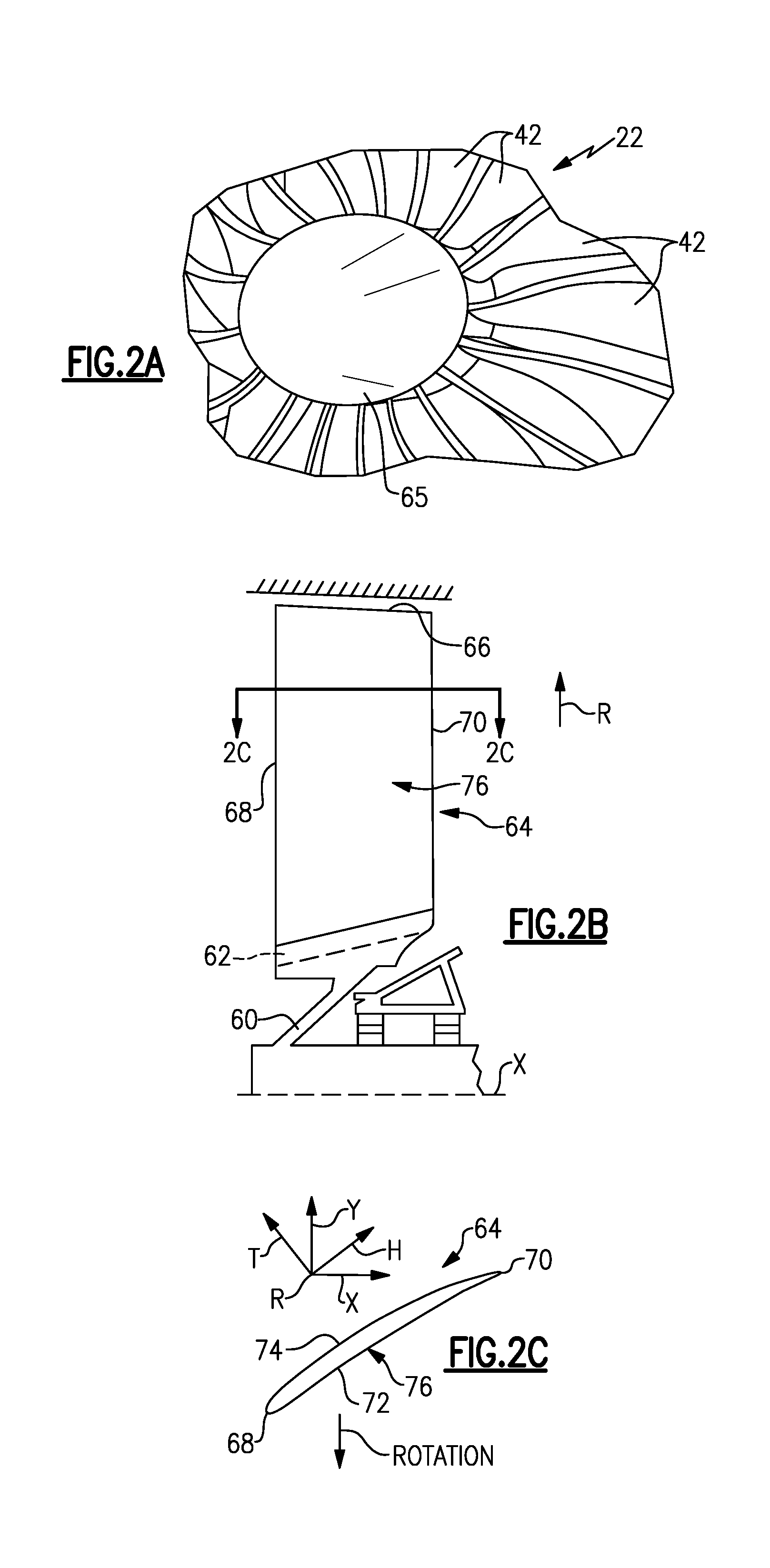
FIG. 2A is a perspective view of a portion of a fan section.
FIG. 2B is a schematic cross-sectional view of the fan section.
FIG. 2C is a cross-sectional view a fan blade taken along line 2C-2C in FIG. 2B.
FIG. 3A is a schematic view of fan blade span positions.
FIG. 3B is a schematic view of a cross-section of a fan blade section at a particular span position and its tangential twist and chord parameters.
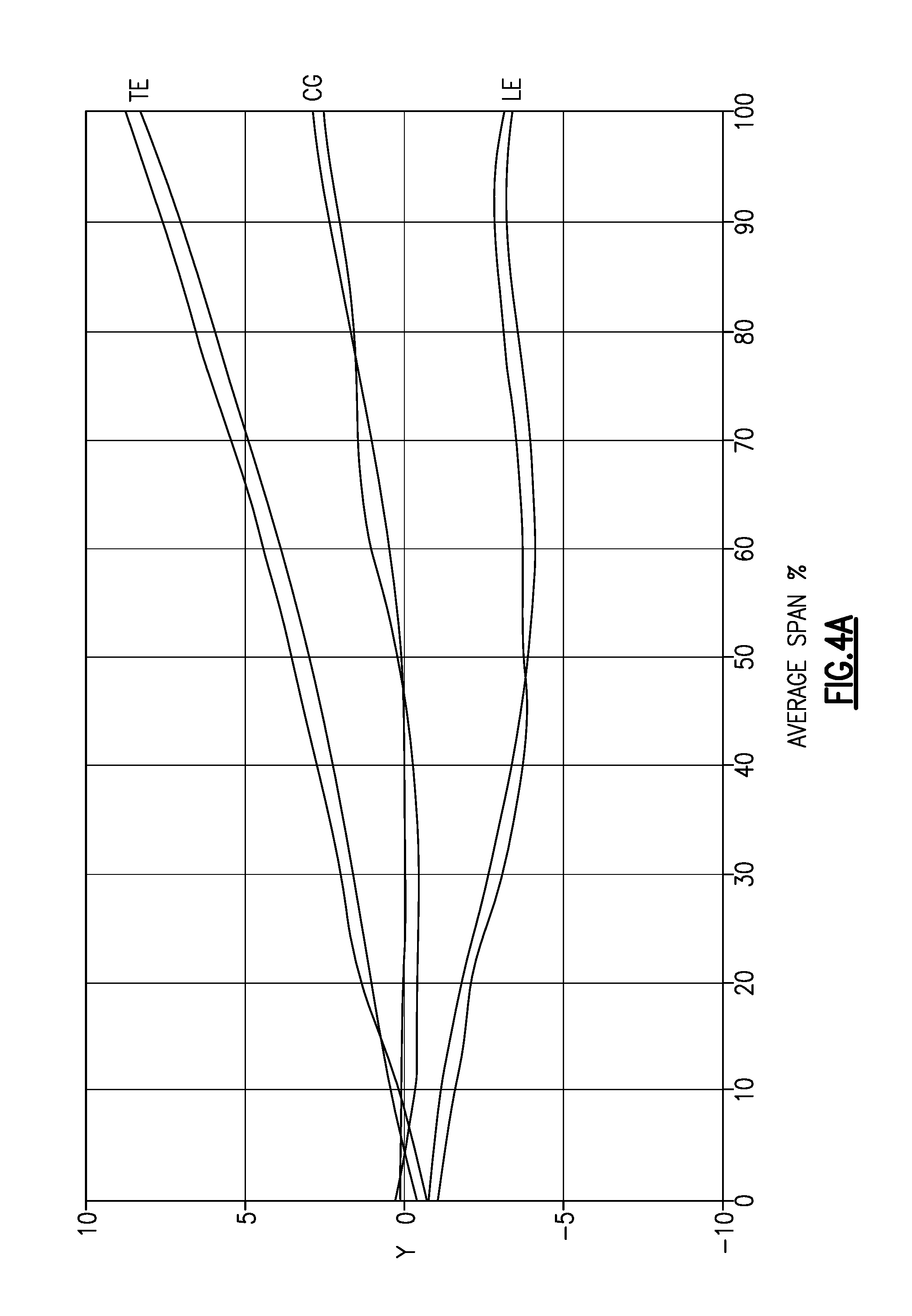
FIG. 4A illustrates a relationship between tangential leading edge position, tangential stacking offset position and tangential trailing edge position relative to span position for a set of first example airfoils.
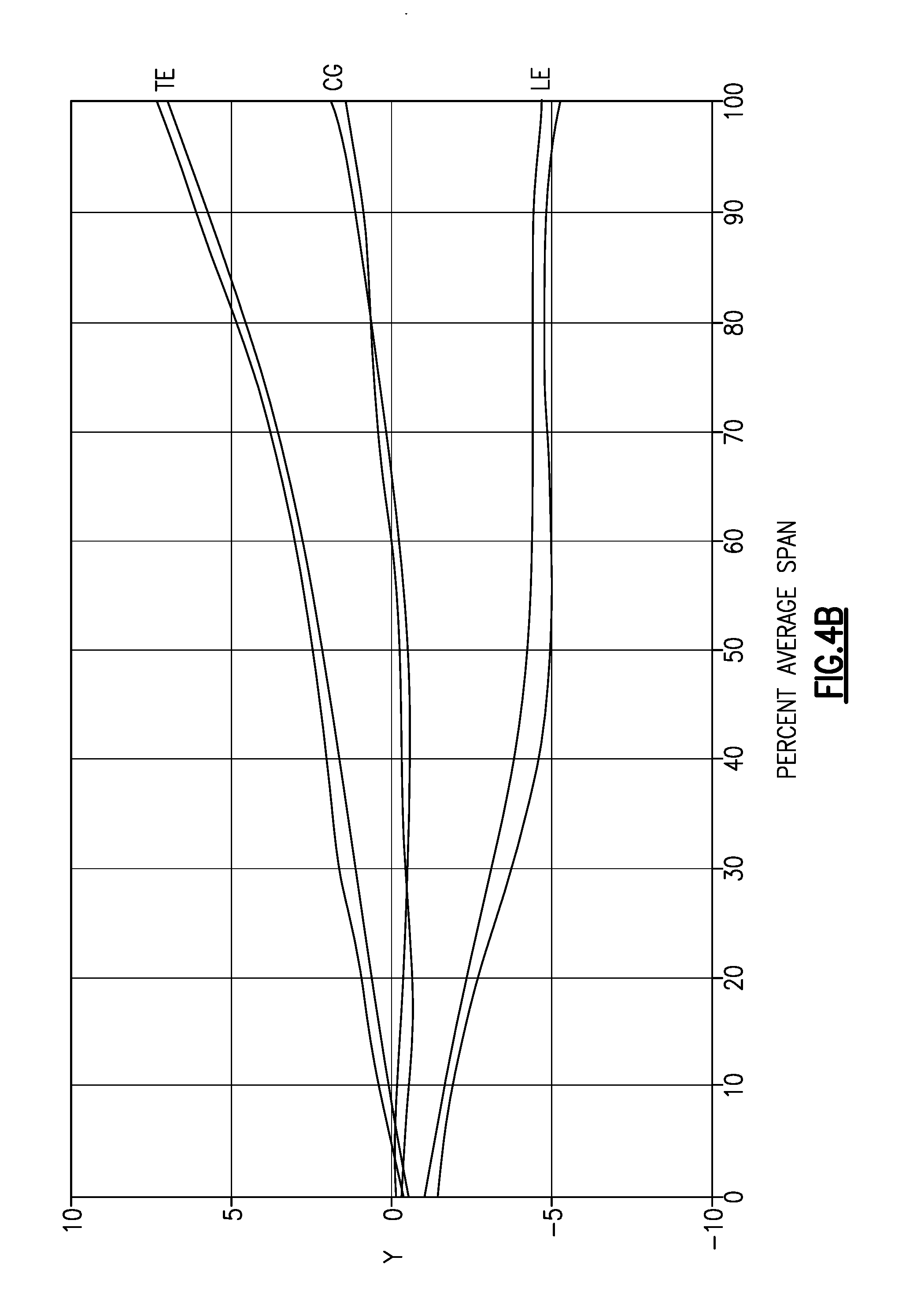
FIG. 4B illustrates a relationship between tangential leading edge position, tangential stacking offset position and tangential trailing edge position relative to span position for a set of second example airfoils.
FIG. 4C illustrates a relationship between tangential leading edge position, tangential stacking offset position and tangential trailing edge position relative to span position for a set of third example airfoils.
The embodiments, examples and alternatives of the preceding paragraphs, the claims, or the following description and drawings, including any of their various aspects or respective individual features, may be taken independently or in any combination. Features described in connection with one embodiment are applicable to all embodiments, unless such features are incompatible.
DETAILED DESCRIPTION
FIG. 1 schematically illustrates a gas turbine engine 20. The gas turbine engine 20 is disclosed herein as a two-spool turbofan that generally incorporates a fan section 22, a compressor section 24, a combustor section 26 and a turbine section 28. Alternative engines might include an augmenter section (not shown) among other systems or features. The fan section 22 drives air along a bypass flow path B in a bypass duct defined within a nacelle 15, while the compressor section 24 drives air along a core flow path C for compression and communication into the combustor section 26 then expansion through the turbine section 28. Although depicted as a two-spool turbofan gas turbine engine in the disclosed non-limiting embodiment, it should be understood that the concepts described herein are not limited to use with two-spool turbofans as the teachings may be applied to other types of turbine engines including three-spool architectures. That is, the disclosed airfoils may be used for engine configurations such as, for example, direct fan drives, or two- or three-spool engines with a speed change mechanism coupling the fan with a compressor or a turbine sections.
The exemplary engine 20 generally includes a low speed spool 30 and a high speed spool 32 mounted for rotation about an engine central longitudinal axis X relative to an engine static structure 36 via several bearing systems 38. It should be understood that various bearing systems 38 at various locations may alternatively or additionally be provided, and the location of bearing systems 38 may be varied as appropriate to the application.
The low speed spool 30 generally includes an inner shaft 40 that interconnects a fan 42, a first (or low) pressure compressor 44 and a first (or low) pressure turbine 46. The inner shaft 40 is connected to the fan 42 through a speed change mechanism, which in exemplary gas turbine engine 20 is illustrated as a geared architecture 48 to drive the fan 42 at a lower speed than the low speed spool 30. The high speed spool 32 includes an outer shaft 50 that interconnects a second (or high) pressure compressor 52 and a second (or high) pressure turbine 54. A combustor 56 is arranged in exemplary gas turbine 20 between the high pressure compressor 52 and the high pressure turbine 54. A mid-turbine frame 57 of the engine static structure 36 is arranged generally between the high pressure turbine 54 and the low pressure turbine 46. The mid-turbine frame 57 further supports bearing systems 38 in the turbine section 28. The inner shaft 40 and the outer shaft 50 are concentric and rotate via bearing systems 38 about the engine central longitudinal axis X which is collinear with their longitudinal axes.
The core airflow is compressed by the low pressure compressor 44 then the high pressure compressor 52, mixed and burned with fuel in the combustor 56, then expanded over the high pressure turbine 54 and low pressure turbine 46. The mid-turbine frame 57 includes airfoils 59 which are in the core airflow path C. The turbines 46, 54 rotationally drive the respective low speed spool 30 and high speed spool 32 in response to the expansion. It will be appreciated that each of the positions of the fan section 22, compressor section 24, combustor section 26, turbine section 28, and fan drive gear system 48 may be varied. For example, gear system 48 may be located aft of combustor section 26 or even aft of turbine section 28, and fan section 22 may be positioned forward or aft of the location of gear system 48.
The engine 20 in one example is a high-bypass geared aircraft engine. In a further example, the engine 20 bypass ratio is greater than about six (6), with an example embodiment being greater than about ten (10), the geared architecture 48 is an epicyclic gear train, such as a planetary gear system or other gear system, with a gear reduction ratio of greater than about 2.3 and the low pressure turbine 46 has a pressure ratio that is greater than about five. In one disclosed embodiment, the engine 20 bypass ratio is greater than about ten (10:1), the fan diameter is significantly larger than that of the low pressure compressor 44, and the low pressure turbine 46 has a pressure ratio that is greater than about five (5:1). Low pressure turbine 46 pressure ratio is pressure measured prior to inlet of low pressure turbine 46 as related to the pressure at the outlet of the low pressure turbine 46 prior to an exhaust nozzle. The geared architecture 48 may be an epicyclic gear train, such as a planetary gear system or other gear system, with a gear reduction ratio of greater than about 2.3:1. It should be understood, however, that the above parameters are only exemplary of one embodiment of a geared architecture engine and that the present invention is applicable to other gas turbine engines including direct drive turbofans.
The example gas turbine engine includes the fan 42 that comprises in one non-limiting embodiment less than about twenty-six (26) fan blades. In another non-limiting embodiment, the fan section 22 includes less than about twenty (20) fan blades. Moreover, in one disclosed embodiment the low pressure turbine 46 includes no more than about six (6) turbine rotors schematically indicated at 34. In another non-limiting example embodiment the low pressure turbine 46 includes about three (3) turbine rotors. A ratio between the number of fan blades 42 and the number of low pressure turbine rotors is between about 3.3 and about 8.6. The example low pressure turbine 46 provides the driving power to rotate the fan section 22 and therefore the relationship between the number of turbine rotors 34 in the low pressure turbine 46 and the number of blades 42 in the fan section 22 disclose an example gas turbine engine 20 with increased power transfer efficiency.
A significant amount of thrust is provided by the bypass flow B due to the high bypass ratio. The fan section 22 of the engine 20 is designed for a particular flight condition--typically cruise at about 0.8 Mach and about 35,000 feet. The flight condition of 0.8 Mach and 35,000 ft, with the engine at its best fuel consumption--also known as "bucket cruise Thrust Specific Fuel Consumption (`TSFC`)"--is the industry standard parameter of lbm of fuel being burned divided by lbf of thrust the engine produces at that minimum point. "Low fan pressure ratio" is the pressure ratio across the fan blade alone, without a Fan Exit Guide Vane ("FEGV") system. The low fan pressure ratio as disclosed herein according to one non-limiting embodiment is less than about 1.55. In another non-limiting embodiment the low fan pressure ratio is less than about 1.45. In another non-limiting embodiment the low fan pressure ratio is from 1.1 to 1.45. "Low corrected fan tip speed" is the actual fan tip speed in ft/sec divided by an industry standard temperature correction of [(Tram .degree. R)/(518.7.degree. R)].sup.0.5. The "Low corrected fan tip speed" as disclosed herein according to one non-limiting embodiment is less than about 1200 ft/second.
Referring to FIG. 2A-2C, the fan blade 42 is supported by a fan hub 60 that is rotatable about the axis X. Each fan blade 42 includes an airfoil 64 extending in a radial span direction R from a root 62 to a tip 66. A 0% span position corresponds to a section of the airfoil 64 at the inner flow path (e.g., a platform), and a 100% span position corresponds to a section of the airfoil 64 at the tip 66.
The root 62 is received in a correspondingly shaped slot in the fan hub 60. The airfoil 64 extends radially outward of the platform, which provides the inner flow path. The platform may be integral with the fan blade or separately secured to the fan hub, for example. A spinner 65 is supported relative to the fan hub 60 to provide an aerodynamic inner flow path into the fan section 22.
The airfoil 64 has an exterior surface 76 providing a contour that extends from a leading edge 68 aftward in a chord-wise direction H to a trailing edge 70, as shown in FIG. 2C. Pressure and suction sides 72, 74 join one another at the leading and trailing edges 68, 70 and are spaced apart from one another in an airfoil thickness direction T. An array of the fan blades 42 are positioned about the axis X in a circumferential or tangential direction Y. Any suitable number of fan blades may be used in a given application.
The exterior surface 76 of the airfoil 64 generates lift based upon its geometry and directs flow along the core flow path C. The fan blade 42 may be constructed from a composite material, or an aluminum alloy or titanium alloy, or a combination of one or more of these. Abrasion-resistant coatings or other protective coatings may be applied to the fan blade 42.
One characteristic of fan blade performance relates to the fan blade's tangential stacking offset and leading and trailing edge positions (Y direction) relative to a particular span position (R direction). Referring to FIG. 3A, span positions are schematically illustrated from 0% to 100% in 10% increments (i.e., 0, 10, 20, 30, 40, 50, 60, 70, 80, 90, 100). Each section at a given span position is provided by a conical cut that corresponds to the shape of the core flow path, as shown by the large dashed lines. In the case of a fan blade with an integral platform, the 0% span position corresponds to the radially innermost location where the airfoil meets the fillet joining the airfoil to the platform. In the case of a fan blade without an integral platform, the 0% span position corresponds to the radially innermost location where the discrete platform meets the exterior surface of the airfoil. In addition to varying with span, tangential projection varies between a hot, running condition and a cold, static ("on the bench") condition.
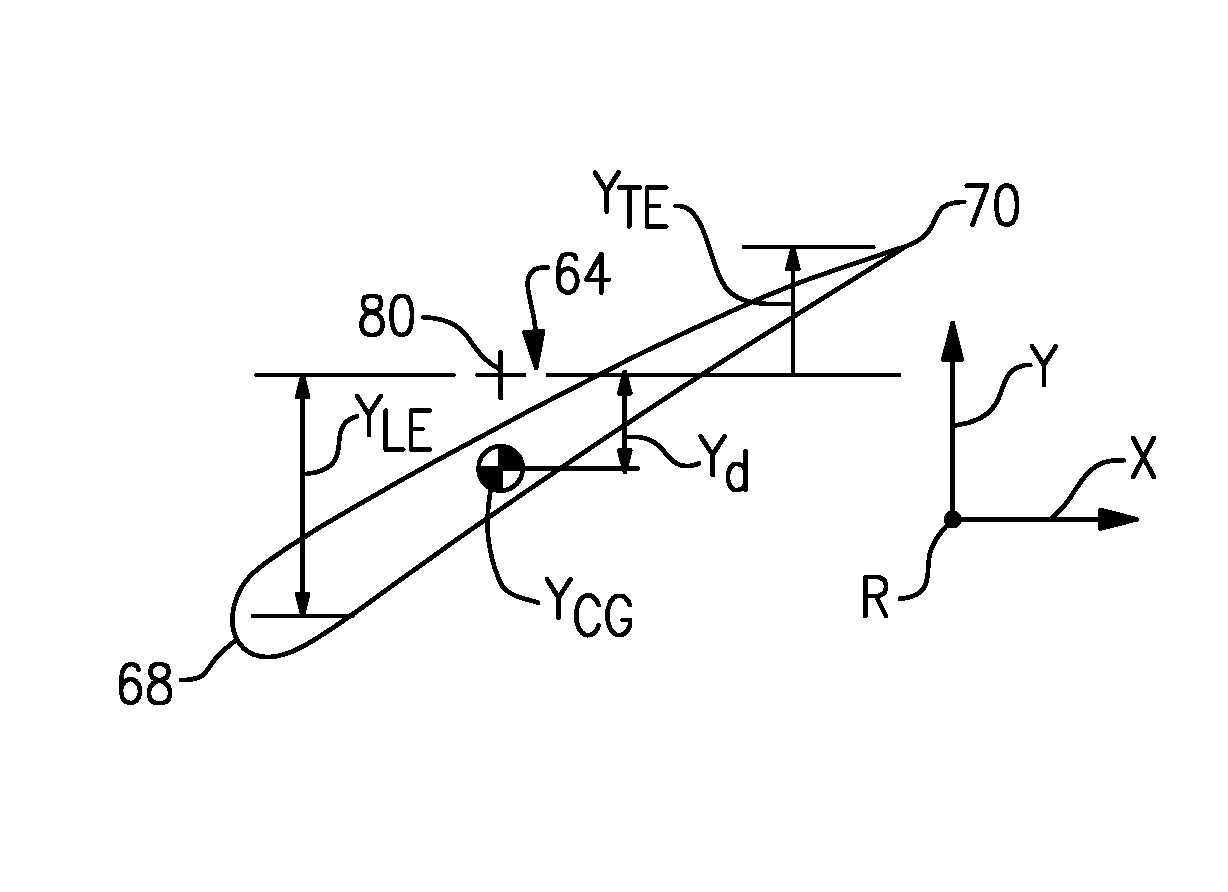
The Y.sub.CG corresponds to the location of the center of gravity (CG) for a particular section at a given span location relative to a reference point 80 in the Y direction, as shown in FIG. 3B. The center of gravity assumes a homogeneous material. The reference point 80 is the tangential center of the root, and Y.sub.d corresponds to the circumferential distance from the reference point 80 to the center of gravity.
A positive Y value corresponds to the opposite rotational direction as the hub's rotation, or toward the suction side of the airfoil. A negative Y value corresponds to the same rotational direction as the hub's rotation, or toward the pressure side of the airfoil.
The tangential leading edge location (TE) is arranged at the leading edge 68 for a particular section at a given span location relative to the reference point 80 in the Y direction (Y), as shown in FIG. 3B. YLE corresponds to the circumferential distance from the reference point 80 to the tangential leading edge location at a given span location.
The tangential trailing edge location (LE) is arranged at the trailing edge 70 for a particular section at a given span location relative to the reference point 80 in the Y direction (Y). YTE corresponds to the circumferential distance from the reference point 80 to the tangential trailing edge location at a given span location.
The changes in fan blade tangential projection at various span positions can be expressed using the differences Y.sub.LE-Y.sub.d and Y.sub.d-Y.sub.TE, which are tangential distances between the locations. These differences can be used to provide non-dimensional ratios indicative of desired airfoil characteristics.
In one prior art airfoil, (Y.sub.LE-Y.sub.d)/(Y.sub.d-Y.sub.TE) at 100% span position is about 0.94 and (Y.sub.LE-Y.sub.d)/(Y.sub.d-Y.sub.TE) at 90% span position is about 1; (Y.sub.LE-Y.sub.d)/(Y.sub.d-Y.sub.TE) at 60% span position is about 1.16 and (Y.sub.LE-Y.sub.d)/(Y.sub.d-Y.sub.TE) at 50% span position is about 1.56; and (Y.sub.LE-Y.sub.d)/(Y.sub.d-Y.sub.TE) at 40% span position is about 1.5 and (Y.sub.LE-Y.sub.d)/(Y.sub.d-Y.sub.TE) at 20% span position is about 1.75.
Example relationships between the tangential projection relative to the span position are shown in FIGS. 4A-4C for several example fan blades, each represented by a curve. Only one curve in each graph is discussed for simplicity. The tangential trailing edge curve crosses the tangential stacking offset in the range of 4-10% span position. "About" used in relation to the (Y.sub.LE-Y.sub.d)/(Y.sub.d-Y.sub.TE) ratios means+/-0.10 in one example, and +/-0.05 in another example.
Referring to FIG. 4A, (Y.sub.LE-Y.sub.d)/(Y.sub.d-Y.sub.TE) at 100% span position is about 1.1 and (Y.sub.LE-Y.sub.d)/(Y.sub.d-Y.sub.TE) at 90% span position is about 1.3; (Y.sub.LE-Y.sub.d)/(Y.sub.d-Y.sub.TE) at 60% span position is about 1.8 and (Y.sub.LE-Y.sub.d)/(Y.sub.d-Y.sub.TE) at 50% span position is about 0.75; and (Y.sub.LE-Y.sub.d)/(Y.sub.d-Y.sub.TE) at 40% span position is about 1.5 and (Y.sub.LE-Y.sub.d)/(Y.sub.d-Y.sub.TE) at 20% span position is about 2.
Referring to FIG. 4B, (Y.sub.LE-Y.sub.d)/(Y.sub.d-Y.sub.TE) at 100% span position is about 1 and (Y.sub.LE-Y.sub.d)/(Y.sub.d-Y.sub.TE) at 90% span position is about 1.2; (Y.sub.LE-Y.sub.d)/(Y.sub.d-Y.sub.TE) at 60% span position is about 1.3 and (Y.sub.LE-Y.sub.d)/(Y.sub.d-Y.sub.TE) at 50% span position is about 1.4; and (Y.sub.LE-Y.sub.d)/(Y.sub.d-Y.sub.TE) at 40% span position is about 1.5 and (Y.sub.LE-Y.sub.d)/(Y.sub.d-Y.sub.TE) at 20% span position is about 2.
Referring to FIG. 4C, (Y.sub.LE-Y.sub.d)/(Y.sub.d-Y.sub.TE) at 100% span position is about 1.1 and (Y.sub.LE-Y.sub.d)/(Y.sub.d-Y.sub.TE) at 90% span position is about 1; (Y.sub.LE-Y.sub.d)/(Y.sub.d-Y.sub.TE) at 60% span position is about 1.4 and (Y.sub.LE-Y.sub.d)/(Y.sub.d-Y.sub.TE) at 50% span position is about 1.2; and (Y.sub.LE-Y.sub.d)/(Y.sub.d-Y.sub.TE) at 40% span position is about 1.5 and (Y.sub.LE-Y.sub.d)/(Y.sub.d-Y.sub.TE) at 20% span position is about 2.
The tangential leading and trailing edge positions and tangential stacking offsets in a hot, running condition along the span of the airfoils 64 relate to the contour of the airfoil and provide necessary fan operation in cruise at the lower, preferential speeds enabled by the geared architecture 48 in order to enhance aerodynamic functionality and thermal efficiency. As used herein, the hot, running condition is the condition during cruise of the gas turbine engine 20. For example, the tangential leading and trailing edge positions and tangential stacking offsets in the hot, running condition can be determined in a known manner using numerical analysis, such as finite element analysis.
It should also be understood that although a particular component arrangement is disclosed in the illustrated embodiment, other arrangements will benefit herefrom. Although particular step sequences are shown, described, and claimed, it should be understood that steps may be performed in any order, separated or combined unless otherwise indicated and will still benefit from the present invention.
Although the different examples have specific components shown in the illustrations, embodiments of this invention are not limited to those particular combinations. It is possible to use some of the components or features from one of the examples in combination with features or components from another one of the examples.
Although an example embodiment has been disclosed, a worker of ordinary skill in this art would recognize that certain modifications would come within the scope of the claims. For that reason, the following claims should be studied to determine their true scope and content.
* * * * *
References
D00000
D00001
D00002
D00003
D00004
D00005
D00006
XML
uspto.report is an independent third-party trademark research tool that is not affiliated, endorsed, or sponsored by the United States Patent and Trademark Office (USPTO) or any other governmental organization. The information provided by uspto.report is based on publicly available data at the time of writing and is intended for informational purposes only.
While we strive to provide accurate and up-to-date information, we do not guarantee the accuracy, completeness, reliability, or suitability of the information displayed on this site. The use of this site is at your own risk. Any reliance you place on such information is therefore strictly at your own risk.
All official trademark data, including owner information, should be verified by visiting the official USPTO website at www.uspto.gov. This site is not intended to replace professional legal advice and should not be used as a substitute for consulting with a legal professional who is knowledgeable about trademark law.