Airfoil tip geometry to reduce blade wear in gas turbine engines
Raghavan , et al. A
U.S. patent number 10,385,865 [Application Number 15/063,089] was granted by the patent office on 2019-08-20 for airfoil tip geometry to reduce blade wear in gas turbine engines. This patent grant is currently assigned to General Electric Company. The grantee listed for this patent is General Electric Company. Invention is credited to Ananda Barua, Kenneth Martin Lewis, Sathyanarayanan Raghavan, Neelesh Nandkumar Sarawate, Changjie Sun.


| United States Patent | 10,385,865 |
| Raghavan , et al. | August 20, 2019 |
Airfoil tip geometry to reduce blade wear in gas turbine engines
Abstract
An airfoil for use in a turbomachine includes a pressure sidewall and a suction sidewall coupled to the pressure sidewall. The suction sidewall and the pressure sidewall define a leading edge and an opposite trailing edge. The leading edge and the trailing edge define a chord distance. The airfoil further includes a root portion, and a tip portion. The tip portion extends between the pressure sidewall and the suction sidewall such that the tip portion is substantially perpendicular to each sidewall. The tip portion includes at least one planar section and at least one oblique section that forms a recess within the tip portion. The at least one oblique section extends from the at least one planar section towards the root portion along the chord distance. The tip portion is configured to reduce airfoil wear during contact with a surrounding casing.
| Inventors: | Raghavan; Sathyanarayanan (Ballston Lake, NY), Sarawate; Neelesh Nandkumar (Niskayuna, NY), Lewis; Kenneth Martin (Liberty Township, OH), Sun; Changjie (Clifton Park, NY), Barua; Ananda (Schenectady, NY) | ||||||||||
|---|---|---|---|---|---|---|---|---|---|---|---|
| Applicant: |
|
||||||||||
| Assignee: | General Electric Company
(Schenectady, NY) |
||||||||||
| Family ID: | 59723483 | ||||||||||
| Appl. No.: | 15/063,089 | ||||||||||
| Filed: | March 7, 2016 |
Prior Publication Data
| Document Identifier | Publication Date | |
|---|---|---|
| US 20170254340 A1 | Sep 7, 2017 | |
| Current U.S. Class: | 1/1 |
| Current CPC Class: | F04D 29/324 (20130101); F04D 29/164 (20130101) |
| Current International Class: | F04D 29/16 (20060101); F04D 29/32 (20060101) |
| Field of Search: | ;415/173.1 |
References Cited [Referenced By]
U.S. Patent Documents
| 4874290 | October 1989 | Cang et al. |
| 5018942 | May 1991 | Ciokajlo et al. |
| 5031313 | July 1991 | Blair |
| 5048183 | September 1991 | Cang et al. |
| 5660523 | August 1997 | Lee |
| 6059532 | May 2000 | Chen |
| 6502304 | January 2003 | Rigney et al. |
| 6616410 | September 2003 | Grylls et al. |
| 6672829 | January 2004 | Cherry et al. |
| 8172518 | May 2012 | Ruehr et al. |
| 8657570 | February 2014 | Kray et al. |
| 8790088 | July 2014 | Dyer et al. |
| 8858167 | October 2014 | Baumann |
| 9114496 | August 2015 | Saunders et al. |
| 2005/0106030 | May 2005 | Bachofner |
| 2009/0269189 | October 2009 | Bottome |
| 2011/0293436 | December 2011 | Di Florio |
| 2012/0034101 | February 2012 | James et al. |
| 2012/0328447 | December 2012 | Hofmann |
| 2013/0089421 | April 2013 | Nussbaum |
| 2013/0142651 | June 2013 | Lim |
| 2015/0204347 | July 2015 | Strock et al. |
Other References
|
Padova, Corso et al.; "Casing Treatment and Blade-Tip Configuration Effects on Controlled Gas Turbine Blade Tip/Shroud Rubs at Engine Conditions;" Journal of Turbomachinery; Jan. 2011; vol. 133, 12 pp. cited by applicant . Padova, Corso et al.; "Experimental Results from Controlled Blade Tip/Shroud Rubs at Engine Speed;" Journal of Turbomachinery; Oct. 2007; vol. 129, 11 pp. cited by applicant . Papa, M. et al; "Effects of Tip Geometry and Tip Clearance on the Mass/Heat Transfer from a Large-Scale Gas Turbine Blade;" ASME Turbo Expo 2002: Power for Land, Sea and Air; Jun. 3-6, 2002; Amsterdam, The Netherlands; 10 pp. cited by applicant. |
Primary Examiner: Rivera; Carlos A
Assistant Examiner: Pruitt; Justin A
Attorney, Agent or Firm: Armstrong Teasdale LLP
Claims
What is claimed is:
1. An airfoil for use in a turbomachine, said airfoil comprising: a pressure sidewall; a suction sidewall coupled to said pressure sidewall, wherein said suction sidewall and said pressure sidewall define a leading edge and an opposite trailing edge, wherein said leading edge and said trailing edge define a chord distance; a root portion; and a tip portion extending between said pressure sidewall and said suction sidewall such that said tip portion is substantially perpendicular to each sidewall, said tip portion comprises at least one planar section and at least one oblique section that forms a recess within said tip portion, said at least one oblique section extends from said at least one planar section towards said root portion along said chord distance, said tip portion is configured to reduce airfoil wear during contact with a surrounding casing, wherein said at least one oblique section comprises a first oblique section and a second oblique section, said first oblique section extends convexly from said leading edge to said at least one planar section and said second oblique section extends concavely from said trailing edge to said at least one planar section.
2. The airfoil in accordance with claim 1, wherein said at least one oblique section extends from said leading edge within a range from approximately 5% to approximately 15% of said chord distance to said at least one planar section, wherein said leading edge has a first length that extends between said root portion and said at least one oblique section and said trailing edge has a second length that extends between said root portion and said at least one planar section such that said first length is less than said second length, and wherein the at least one planar section defines a radially outer surface of the airfoil.
3. The airfoil in accordance with claim 1, wherein said at least one oblique section extends from said leading edge within a range from approximately 15% to approximately 30% of said chord distance to said at least one planar section, wherein said leading edge has a first length that extends between said root portion and said at least one oblique section and said trailing edge has a second length that extends between said root portion and said at least one planar section such that said first length is less than said second length.
4. The airfoil in accordance with claim 1, wherein said at least one oblique section extends from said leading edge within a range from approximately 30% to approximately 50% of said chord distance to said at least one planar section, wherein said leading edge has a first length that extends between said root portion and said at least one oblique section and said trailing edge has a second length that extends between said root portion and said at least one planar section such that said first length is less than said second length.
5. The airfoil in accordance with claim 1, wherein said at least one oblique section extends from said trailing edge within a range from approximately 5% to approximately 15% of said chord distance to said at least one planar section, wherein said leading edge has a first length that extends between said root portion and said at least one planar section and said trailing edge has a second length that extends between said root portion and said at least one oblique section such that said first length is greater than said second length.
6. The airfoil in accordance with claim 1, wherein said at least one oblique section extends from said trailing edge within a range from approximately 15% to approximately 30% of said chord distance to said at least one planar section, wherein said leading edge has a first length that extends between said root portion and said at least one planar section and said trailing edge has a second length that extends between said root portion and said at least one oblique section such that said first length is greater than said second length.
7. The airfoil in accordance with claim 1, wherein said at least one oblique section extends from said trailing edge within a range from approximately 30% to approximately 50% of said chord distance to said at least one planar section, wherein said leading edge has a first length that extends between said root portion and said at least one planar section and said trailing edge has a second length that extends between said root portion and said at least one oblique section such that said first length is greater than said second length.
8. The airfoil in accordance with claim 2, wherein said at least one oblique section comprises a first oblique section and a second oblique section, said first oblique section extends from said leading edge approximately 15% of said chord distance to said at least one planar section and said second oblique section extends from said trailing edge approximately 15% of said chord distance to said at least one planar section.
9. The airfoil in accordance with claim 8, the at least one planar section comprising exactly one planar section, the exactly one planar section extending from the first oblique section to the second oblique section, wherein said leading edge has a first length that extends between said root portion and said first oblique section and said trailing edge has a second length that extends between said root portion and said second oblique section such that said first length is substantially equal to said second length.
10. The airfoil in accordance with claim 1, wherein said at least one oblique section extends from said at least one planer section towards said root portion within a range including approximately 2 mils to less than 5 mils.
11. The airfoil in accordance with claim 1, wherein said at least one planar section comprises a first planar section adjacent said leading edge and a second planar section adjacent trailing edge, said at least one oblique section extends between said first planar section and said second planar section.
12. The airfoil in accordance with claim 9, wherein said at least one oblique section is defined with a convex curve.
13. A turbomachine comprising: a casing; a rotor assembly, said casing at least partially extending about said rotor assembly, said rotor assembly comprising: a rotor shaft; a plurality of rotor blades coupled to said rotor shaft, each rotor blade of said plurality of rotor blades comprises an airfoil comprising a pressure sidewall and a suction sidewall coupled to said pressure sidewall, wherein said suction sidewall and said pressure sidewall define a leading edge and an opposite trailing edge, wherein said leading edge and said trailing edge define a chord distance, said airfoil further comprising a root portion and a tip portion extending between said pressure sidewall and said suction sidewall such that said tip portion is substantially perpendicular to each sidewall, said tip portion comprising at least one planar section and at least one oblique section that forms a recess within said tip portion, said at least one oblique section extends from said at least one planar section towards said root portion along said chord distance, said tip portion is configured to reduce rotor blade wear during contact with said casing, wherein said at least one oblique section comprises a first oblique section and a second oblique section, said first oblique section extends convexly from said leading edge approximately 15% of said chord distance to said at least one planar section and said second oblique section extends concavely from said trailing edge approximately 15% of said chord distance to said at least one planar section.
14. The turbomachine in accordance with claim 13, wherein said at least one oblique section extends from said leading edge to said at least one planar section, wherein a distance measured between said casing and said leading edge is greater than a distance measured between said casing and said trailing edge, and wherein each rotor blade of the plurality of rotor blades comprises a turbine rotor blade.
15. The turbomachine in accordance with claim 13, wherein said at least one oblique section extends from said trailing edge to said at least one planar section, wherein a distance measured between said casing and said trailing edge is greater than a distance measured between said casing and said leading edge.
16. A method for reducing blade wear during turbomachine operation, the turbomachine including a casing, a rotor shaft, and a plurality of rotor blades, each rotor blade of the plurality of rotor blades including an airfoil including a pressure sidewall and a suction sidewall coupled to the pressure sidewall, wherein the suction sidewall and the pressure sidewall define a leading edge and an opposite trailing edge, wherein the leading edge and the trailing edge define a chord distance, the airfoil further includes a root portion and a tip portion extending between the pressure sidewall and the suction sidewall such that the tip portion is substantially perpendicular to each sidewall, said method comprising: removing blade material from the tip portion comprising forming a recess from at least one oblique section adjacent at least one planar section on the tip portion, the at least one oblique section extends from the at least one planar section towards the root portion along the chord distance; and coupling the rotor blade to the rotor shaft such that during turbomachine operation when the tip portion contacts the casing, wear of the rotor blade is reduced, wherein the at least one oblique section extends from the at least one planar section to at least one of the leading edge and the trailing edge, wherein said at least one oblique section comprises a first oblique section and a second oblique section, said first oblique section extends convexly from said leading edge to said at least one planar section and said second oblique section extends concavely from said trailing edge to said at least one planar section.
17. The method in accordance with claim 16, wherein removing blade material from the tip portion further comprises removing blade material from the tip portion at the leading edge such that the leading edge has a first length that extends between the root portion and the at least one oblique section and the trailing edge has a second length that extends between the root portion and the at least one planar section such that the first length is less than the second length.
18. The method in accordance with claim 16, wherein removing blade material from the tip portion further comprises removing blade material from the tip portion at the trailing edge such that the leading edge has a first length that extends between the root portion and the at least one planar section and the trailing edge has a second length that extends between the root portion and the at least one oblique section such that the first length is greater than the second length, and wherein the recess is not centered about a mid-chord line.
19. The method in accordance with claim 16, wherein removing blade material from the tip portion further comprises: removing the leading edge tip portion via a grinding process to form a first oblique section; and removing the trailing edge tip portion via a grinding process to form a second oblique section.
Description
BACKGROUND
The field of the disclosure relates generally to gas turbine engines and, more particularly, to airfoil tip geometry to reduce blade wear in gas turbine engines.
At least some known turbomachines, i.e., gas turbine engines, include a compressor that compresses air through a plurality of rotatable compressor blades enclosed within a compressor casing, and a combustor that ignites a fuel-air mixture to generate combustion gases. The combustion gases are channeled through rotatable turbine blades in a turbine through a hot gas path. Such known turbomachines convert thermal energy of the combustion gas stream to mechanical energy used to generate thrust and/or rotate a turbine shaft to power an aircraft. Output from the turbomachine may also be used to power a machine, such as, an electric generator, a compressor, or a pump.
Under some known operating conditions, rub events occur within the turbomachine, wherein a rotor blade tip contacts or rubs against the surrounding stationary casing inducing radial and tangential loads into a rotor blade airfoil. Generally during rub events, these loads cause the rotor blade to vibrate and deflect causing wear thereto. Excessive tip rub events cause wear to the rotor blade including, but not limited to, loss of blade material, which decreases turbomachine performance.
During tip rub events, the rotor blade is known to lose more material from the tip than the penetration distance into the casing. For example, if the blade tip penetrates the casing 1 mil (25.4 micrometers (.mu.m)) then the blade tip is known to lose as much as 10 mils (254 .mu.m) of material. The thickness of material lost in the blade tip divided by the penetration distance into the casing is known as a rub ratio. In the above example, the rub ratio would be 10:1, or known to have a rub ratio value of 10. Turbomachines with a high rub ratio are known to have decreased performance and decreased service life resulting in higher maintenance costs.
BRIEF DESCRIPTION
In one aspect, an airfoil for use in a turbomachine is provided. The airfoil includes a pressure sidewall and a suction sidewall coupled to the pressure sidewall, the suction sidewall and the pressure sidewall define a leading edge and an opposite trailing edge. The leading edge and the trailing edge define a chord distance. The airfoil further includes a root portion, and a tip portion. The tip portion extends between the pressure sidewall and the suction sidewall such that the tip portion is substantially perpendicular to each sidewall. The tip portion includes at least one planar section and at least one oblique section that forms a recess within the tip portion. The at least one oblique section extends from the at least one planar section towards the root portion to along the chord distance. The tip portion is configured to reduce airfoil wear during contact with a surrounding casing.
In a further aspect, a turbomachine is provided. The turbomachine includes a casing, and a rotor assembly, the casing at least partially extending about the rotor assembly. The rotor assembly includes a rotor shaft, and a plurality of rotor blades coupled to the rotor shaft. Each rotor blade of the plurality of rotor blades includes an airfoil including a pressure sidewall and a suction sidewall coupled to the pressure sidewall. The suction sidewall and the pressure sidewall define a leading edge and an opposite trailing edge. The leading edge and the trailing edge define a chord distance. The airfoil further includes a root portion, and a tip portion. The tip portion extends between the pressure sidewall and the suction sidewall such that the tip portion is substantially perpendicular to each sidewall. The tip portion includes at least one planar section and at least one oblique section that forms a recess within said tip portion. The at least one oblique section slopes from the at least one planar section towards the root portion along the chord distance. The tip portion is configured to reduce rotor blade wear during contact with the casing.
In another aspect, a method for reducing blade wear during turbomachine operation is provided. The turbomachine includes a casing, a rotor shaft, and a plurality of rotor blades. Each rotor blade of the plurality of rotor blades includes an airfoil including a pressure sidewall and a suction sidewall coupled to the pressure sidewall. The suction sidewall and the pressure sidewall define a leading edge and an opposite trailing edge. The leading edge and the trailing edge define a chord distance. The airfoil further includes a root portion, and a tip portion. The tip portion extends between the pressure sidewall and the suction sidewall such that the tip portion is substantially perpendicular to each sidewall. The method includes removing blade material from the tip portion including forming a recess from at least one oblique section adjacent to at least one planar section on the tip portion. The at least one oblique section extends from the at least one planar section towards the root portion along the chord distance. The method further includes coupling the rotor blade to the rotor shaft such that during turbomachine operation, when the tip portion contacts the casing, wear of the rotor blade is reduced.
DRAWINGS
These and other features, aspects, and advantages of the present disclosure will become better understood when the following detailed description is read with reference to the accompanying drawings in which like characters represent like parts throughout the drawings, wherein:
FIG. 1 is a schematic diagram of an exemplary turbomachine, i.e., a turbofan;
FIG. 2 is a perspective view of an exemplary rotor blade that may be used within the turbomachine shown in FIG. 1;
FIG. 3 is a schematic view of an exemplary tip portion of the rotor blade shown in FIG. 2;
FIG. 4 is a graphical view of operational features of the tip portion shown in FIG. 3;
FIG. 5 is a schematic view of an alternative tip portion that may be used with the rotor blade shown in FIG. 2;
FIG. 6 is a schematic view of another alternative tip portion that may be used with the rotor blade shown in FIG. 2; and
FIG. 7 is a schematic view of a further alternative tip portion that may be used with the rotor blade shown in FIG. 2.
Unless otherwise indicated, the drawings provided herein are meant to illustrate features of embodiments of this disclosure. These features are believed to be applicable in a wide variety of systems comprising one or more embodiments of this disclosure. As such, the drawings are not meant to include all conventional features known by those of ordinary skill in the art to be required for the practice of the embodiments disclosed herein.
DETAILED DESCRIPTION
In the following specification and claims, reference will be made to a number of terms, which shall be defined to have the following meanings.
The singular forms "a", "an", and "the" include plural references unless the context clearly dictates otherwise.
"Optional" or "optionally" means that the subsequently described event or circumstance may or may not occur, and that the description includes instances where the event occurs and instances where it does not.
Approximating language, as used herein throughout the specification and claims, may be applied to modify any quantitative representation that could permissibly vary without resulting in a change in the basic function to which it is related. Accordingly, a value modified by a term or terms, such as "about", "approximately", and "substantially", are not to be limited to the precise value specified. In at least some instances, the approximating language may correspond to the precision of an instrument for measuring the value. Here and throughout the specification and claims, range limitations may be combined and/or interchanged, such ranges are identified and include all the sub-ranges contained therein unless context or language indicates otherwise.
Rotor blade tip geometries as described herein provide a method for reducing blade wear in a turbomachine. Specifically, a rotor blade includes an airfoil having a suction sidewall coupled to a pressure sidewall at a leading edge and a trailing edge. A tip portion extends between the suction sidewall and the pressure sidewall and includes a planar section and an oblique section. In some embodiments, the tip portion includes a first oblique section and a second oblique section. Modifying the rotor blade tip geometry by grinding the tip portion and forming the oblique section reduces the rub ratio of the rotor blade, and thereby, the wear of the rotor blade. Specifically, the oblique section is sized such that a contact area between the rotor blade and a surrounding casing is reduced, thereby decreasing the radial and tangential loads induced into the rotor blade during a rub event. Reducing the loads resulting from a rub event decreases vibration and deflection of the rotor blade and reduces material loss at the tip portion. Furthermore, modifying the rotor blade tip geometry changes the vibratory modes of the rotor blade such that radial elongation is decreased further reducing material loss at the tip portion. Additionally, a reduction in radial deflection allows the rotor blade to be positioned closer to the surrounding casing. Accordingly, decreasing the rub ratio of the rotor blade decreases wear and material loss during a rub event, increases turbomachine performance, and reduces maintenance costs.
As used herein, the terms "axial", and "axially", refer to directions and orientations which extend substantially parallel to a centerline 138, as shown in FIG. 1, of a turbine engine. Moreover, the terms "radial", and "radially", refer to directions and orientations which extend substantially perpendicular to centerline 138 of the turbine engine. In addition, as used herein, the terms "circumferential", and "circumferentially", refer to directions and orientations which extend arcuately about centerline 138 of the turbine engine. The term "fluid", as used herein, includes any medium or material that flows, including, but not limited to, air.
FIG. 1 is a schematic view of a turbomachine 100, i.e., a gas turbine engine, and more specifically, an aircraft engine or turbofan. In the exemplary embodiment, turbomachine 100 includes an air intake section 102, and a compressor section 104 that is coupled downstream from, and in flow communication with, intake section 102. Compressor section 104 is enclosed within a compressor casing 106. A combustor section 108 is coupled downstream from, and in flow communication with, compressor section 104, and a turbine section 110 is coupled downstream from, and in flow communication with, combustor section 108. Turbine section 110 is enclosed within a turbine casing 112 and includes an exhaust section 114 that is downstream from turbine section 110. A combustor housing 116 extends about combustor section 108 and is coupled to compressor casing 106 and turbine casing 112. Moreover, in the exemplary embodiment, turbine section 110 is coupled to compressor section 104 through a rotor assembly 118 that includes, without limitation, a compressor rotor, or drive shaft 120 and a turbine rotor, or drive shaft 122.
In the exemplary embodiment, combustor section 108 includes a plurality of combustor assemblies, i.e., combustors 124 that are each coupled in flow communication with compressor section 104. Combustor section 108 also includes at least one fuel nozzle assembly 126. Each combustor 108 is in flow communication with at least one fuel nozzle assembly 126. Moreover, in the exemplary embodiment, turbine section 110 and compressor section 104 are rotatably coupled to a fan assembly 128 through drive shaft 120. Alternatively, turbomachine 100 may be a gas turbine engine and for example, and without limitation, be rotatably coupled to an electrical generator and/or a mechanical drive application, e.g., a pump. In the exemplary embodiment, compressor section 104 includes at least one compressor stage that includes a compressor blade assembly 130 and an adjacent stationary stator vane assembly 132. Each compressor blade assembly 130 includes a plurality of circumferentially spaced blades (not shown) and is coupled to rotor assembly 118, or, more specifically, compressor drive shaft 120. Each stator vane assembly 132 includes a plurality of circumferentially spaced stator vanes (not shown) and is coupled to compressor casing 106. Also, in the exemplary embodiment, turbine section 110 includes at least one turbine blade assembly 134 and at least one adjacent stationary nozzle assembly 136. Each turbine blade assembly 134 is coupled to rotor assembly 118, or, more specifically, turbine drive shaft 122 along a centerline 138.
In operation, air intake section 102 channels air 140 towards compressor section 104. Compressor section 104 compresses air 140 to higher pressures and temperatures prior to discharging compressed air 142 towards combustor section 108. Compressed air 142 is channeled to fuel nozzle assembly 126, mixed with fuel (not shown), and burned within each combustor 124 to generate combustion gases 144 that are channeled downstream towards turbine section 110. After impinging turbine blade assembly 134, thermal energy is converted to mechanical rotational energy that is used to drive rotor assembly 118. Turbine section 110 drives compressor section 104 and/or fan assembly 128 through drive shafts 120 and 122, and exhaust gases 146 are discharged through exhaust section 114 to the ambient atmosphere.
FIG. 2 is a perspective view of an exemplary rotor blade 200, and more specifically, a compressor blade, that may be found within turbomachine 100 (shown in FIG. 1). In the exemplary embodiment, rotor blade 200 includes an airfoil 202, a platform 204, and a dovetail 206 that is used for mounting rotor blade 200 to compressor drive shaft 120 (shown in FIG. 1). Airfoil 202 includes a root portion 208, adjacent platform 204, and an opposite tip portion 210. Further, airfoil 202 includes a pressure sidewall 212 and an opposite suction sidewall 214. In the exemplary embodiment, pressure sidewall 212 is substantially concave and suction sidewall 214 is substantially convex. Pressure sidewall 212 is coupled to suction sidewall 214 at a leading edge 216 and at an axially spaced trailing edge 218. Trailing edge 218 is spaced chord-wise and downstream from leading edge 216. Pressure sidewall 212 and suction sidewall 214 each extend longitudinally or radially outward in a length 220 from root portion 208 to blade tip portion 210. Along a chord of blade 200, a mid-chord line 217 is defined at the mid-point of the chord. Tip portion 210 is defined between sidewalls 212 and 214 and includes a planar section 222 that is defined as the radially outer surface of blade 200 and substantially perpendicular to each sidewall 212 and 214. Tip portion 210 also includes an oblique section 300 adjacent to planar section 222 and described further below in reference to FIG. 3. In an alternative embodiment, rotor blade 200 may have any other configuration that enables turbomachine to function as described herein.
In the exemplary embodiment, compressor casing 106 circumferentially extends around rotor blade 200, and tip portion 210. Specifically, tip portion 210 at leading edge 216 and oblique section 300 has a gap distance 224 that is substantially not equal to a gap distance 226 of tip portion 210 at trailing edge 218 and planar section 222. Furthermore, a flow path 228 for compressed air 142 (shown in FIG. 1) is defined between compressor casing 106 and shaft 120.
During operation, rotor blade 200 rotates within casing 106 about centerline 138 (shown in FIG. 1). In some operating conditions, such as an imbalanced load, rotor blade 200, specifically tip portion 210, contacts or rubs against casing 106, which is also known as a rub event. Specifically, tip portion 210 is jammed into casing 106, such that radial and tangential loads are induced into rotor blade 200. Generally during rub events, these loads cause rotor blade 200 to vibrate and deflect causing wear thereto. The deflection of rotor blade 200, at least in part, depends on the vibratory modes of the blade that are excited during the rub event. Some vibratory modes are known to increase radial elongation of rotor blade 200 resulting in an increased amount of wear to tip portion 210.
At least some of the wear rotor blade 200 incurs during the rub event includes material loss from tip portion 210. Specifically, when tip portion 210 contacts casing 106, rotor blade 200 loses material at tip portion 210 such that overall length 220 is reduced. A rub ratio is a value that may be used to quantify the amount of wear rotor blade 200 experiences during the rub event. A rub ratio is defined as a thickness of material lost from tip portion 210 during a rub event divided by an amount of penetration by tip portion 210 into casing 106. For example, if tip portion 210 penetrates into the casing 1 mil (25 .mu.m) and 10 mils (101 .mu.m) of blade material is lost from tip portion 210, the rub ratio is 10.
FIG. 3 is a schematic view of an exemplary tip portion 210 for use with rotor blade 200. In the exemplary embodiment, tip portion 210 includes planar section 222 that extends from pressure sidewall 212 to suction sidewall 214 and substantially perpendicular thereto. Additionally, tip portion 210 includes an oblique section 300 that slopes from planar section 222 inwards towards root portion 208 to leading edge 216 forming a recess 301. Oblique section 300 also extends from pressure sidewall 212 to suction sidewall 214 and is substantially perpendicular thereto. In the exemplary embodiment, oblique section 300 extends a distance 302 along tip portion 210. Specifically, oblique section 300 extends along tip portion 210 from leading edge 216 within a range from approximately 5% to approximately 50% of a chord distance 304 of airfoil 202. For example, oblique section 300 extends along tip portion 210 from leading edge 216 within a range from approximately 5% to approximately 15% of a chord distance 304 of airfoil 202. More specifically, in the illustrated embodiment, oblique section 300 extends along tip portion 210 from leading edge 216 approximately 15% of chord distance 304. Oblique section 300 also has a depth 306 from planar section 222 such that a length 308 of leading edge 216 that extends from tip portion 210 to root portion 208 is shorter than a length 310 of trailing edge 218 from tip portion 210 to root portion 208. Said another way, distance 224 (shown in FIG. 2) between casing 106 (shown in FIG. 2) and leading edge 216 is greater than distance 226 (shown in FIG. 2) between casing 106 and trailing edge 218. In the exemplary embodiment, depth 306 is within a range including approximately 2 mils (51 .mu.m) to approximately 5 mils (127 .mu.m). In alternative embodiments, depth 306 may have any other distance that enables tip portion 210 to function as described herein.
In some embodiments, for example, oblique section 300 is formed at line 312 that extends a distance 314 along tip portion 210 from leading edge 216 within a range from approximately 15% to approximately 30% of chord distance 304 forming recess 301. Specifically, in the illustrated embodiment, oblique section line 312 extends approximately 30% of chord distance 304 from leading edge 216. Extending recess 301 further from leading edge 216, such as with oblique section line 312, reduces the area of planar section 222 that contacts with casing 106 during a rub event thereby lowering the contact force between rotor blade 200 and casing 106. In other embodiments, for example, oblique section 300 is formed at line 316 that extends a distance 318 along tip portion 210 from leading edge 216 within a range from approximately 30% to approximately 50% of chord distance 304 forming recess 301. Specifically, in the illustrated embodiment, oblique section line 316 extends approximately 50% of chord distance 304 from leading edge 216. Extending recess 301 further from leading edge 216, such as with oblique section line 316, further reduces the area of planar section 222 that contacts with casing 106 during a rub event thereby lowering the contact force between rotor blade 200 and casing 106. In further embodiments, oblique section 300 may extend any other distance along tip portion 210 from leading edge 216 that enables tip portion 210 to function as described herein.
Additionally, in some embodiments, an oblique section 320 is defined from trailing edge 218 such that a length of trailing edge 218 from tip portion 210 to root portion 208 is shorter than a length of leading edge from tip portion 210 to root portion 208. Said another way, distance 226 between casing 106 and trailing edge 218 is greater than distance 224 between casing 106 and leading edge 216. In the exemplary embodiment, oblique section 320 extends along tip portion 210 from trailing edge 218 within a range from approximately 5% to approximately 50% of chord distance 304 of airfoil 202. For example, oblique section 320 extends a distance 322 from trailing edge 218 within a range from approximately 5% to approximately 15% of chord distance 304 forming a recess 321. Specifically, in the illustrated embodiment, oblique section 320 extends approximately 15% of chord distance 304 from trailing edge 218. In other embodiments, for example, oblique section 320 is formed at line 324 that extends a distance 326 from trailing edge 218 within a range from approximately 15% to approximately 30% of chord distance 304 forming recess 321. Specifically, in the illustrated embodiment, oblique section line 324 extends approximately 30% of chord distance 304 from trailing edge 218. Extending recess 321 further from trailing edge 216, such as with oblique section line 324, reduces the area of planar section 222 that contacts with casing 106 during a rub event thereby lowering the contact force between rotor blade 200 and casing 106. In yet other embodiments, for example, oblique section 320 is formed at line 328 that extends a distance 330 from trailing edge 218 within a range from approximately 30% to approximately 50% of chord distance 304 forming recess 321. Specifically, in the illustrated embodiment, oblique section line 328 extends approximately 50% of chord distance 304 from trailing edge 218. Extending recess 321 further from trailing edge 218, such as with oblique section line 328, reduces the area of planar section 222 that contacts with casing 106 during a rub event thereby lowering the contact force between rotor blade 200 and casing 106. In alternative embodiments, oblique section 320 extends any other distance along tip portion 210 from trailing edge 218 that enables tip portion 210 to function as described herein.
Furthermore, in some embodiments, tip portion 210 includes oblique sections on both leading edge 216 and trailing edge 218. For example, tip portion 210 includes oblique section 300 and oblique section 320 such that a length of leading edge 216 from tip portion 210 to root portion 208 is substantially equal to a length of trailing edge 218 from tip portion 210 to root portion 208. Said another way, distance 224 between casing 106 and leading edge 216 is substantially equal to distance 226 between casing 106 and trailing edge 218.
In the exemplary embodiment, oblique section 300 is formed by grinding tip portion 210 and removing rotor blade 200 material in a machine shop using known machining techniques. Alternatively, oblique section 300 can be formed by any other method that enables rotor blade 200 to function as described herein.
FIG. 4 is a graphical view, i.e., chart 400, of operational features of tip portion 210 shown in FIGS. 2-3. Specifically, chart 400 illustrates a rub ratio value for four different tip geometries of tip portion 210 (shown in FIG. 3). The rub ratio is defined as a thickness of material lost from tip portion 210 during a rub event divided by an amount of penetration by tip portion 210 into casing 106 as described in reference to FIG. 2. Chart 400 includes a y-axis 402 defining the rub ratio value on a linear scale. Along the x-axis, four different tip geometries are shown: a baseline geometry 404, which includes planar section 222 (shown in FIG. 3) that extends the full length of tip portion 210 from leading edge 216 (shown in FIG. 3) to trailing edge 218 (shown in FIG. 3); a first geometry 406, which includes oblique section 300 (shown in FIG. 3) adjacent to leading edge 216; a second geometry 408, which includes oblique section 320 (shown in FIG. 3) adjacent to trailing edge 218; and a third geometry 410, which includes both oblique sections 300 and 320.
In the exemplary chart 400, each tip geometry 404, 406, 408, and 410 is subjected to a rub event with casing 106 (shown in FIG. 1) and a thickness of material loss at each of leading edge 216, mid-chord line 217 (shown in FIG. 3), and trailing edge 218 are recorded. Then the rub ratio at each leading edge 216, mid-chord line 217, and trailing edge 218 are determined. Chart 400 includes a first group of bars 412 that represents the rub ratio for tip portion 210 with baseline geometry 404. A leftmost bar 414 represents the rub ratio at leading edge 216 of baseline geometry 404, a middle bar 416 represents the rub ratio at mid-chord line 217, and a rightmost bar 418 represents the rub ratio at trailing edge 218.
Further, in the exemplary chart 400, a second group of bars 420 represents the rub ratio for tip portion 210 with first tip geometry 406. A leftmost bar 422 represents the rub ratio at leading edge 216 which is less than the rub ratio of baseline geometry 404 thereby reducing wear to tip portion 210 during a rub event. A middle bar 424 represents the rub ratio at mid-chord line 217, and a rightmost bar 426 represents the rub ratio at trailing edge 218.
A third group of bars 428 represents the rub ratio for tip portion 210 with second tip geometry 408. A leftmost bar 430 represents the rub ratio at leading edge 216, a middle bar 432 represents the rub ratio at mid-chord line 217, and a rightmost bar 434 represents the rub ratio at trailing edge 218. At each location, leading edge 216, mid-chord line 217, and trailing edge 218, the rub ratio is less than baseline geometry 404 thereby reducing wear of tip portion 210 during a rub event.
A fourth group of bars 436 represents the rub ratio for tip portion 210 with third tip geometry 410. A leftmost bar 438 represents the rub ratio at leading edge 216, a middle bar 440 represents the rub ratio at mid-chord line 217, and a rightmost bar 442 represents the rub ratio at trailing edge 218. At each location, leading edge 216, mid-chord line 217, and trailing edge 218, the rub ratio is lower than baseline geometry 404 thereby reducing wear of tip portion 210 during a rub event.
As shown in chart 400, modifying the geometry of tip portion 210 and grinding an oblique section, such as oblique section 300 and/or 320 into tip portion 210, reduces the wear of rotor blade 200 (shown in FIG. 3) when compared to baseline geometry 404 without the oblique section. Specifically, modifying tip portion 210 geometry reduces the rub ratio of blade 200. For example, oblique section 300 within tip portion 210 alters the way in which blade 200 contacts casing 106 during a rub event. Oblique section 300 lowers the contact force between rotor blade 200 and casing 106 thereby reducing vibration and deflection. By reducing the radial and tangential loads induced into rotor blade 200, vibration is reduced, thereby reducing radial elongation of rotor blade 200. Additionally, modifying the geometry of tip portion 210 also modifies the vibratory modes that contribute to radial elongation within blade 200. Reducing radial elongation within rotor blade 200 decreases the amount of material loss due to rubbing against casing 106 and thus wear of rotor blade 200. In alternative embodiments, modifying the geometry of tip portion 210 results in different rub ratio values of blade 200 then illustrated in chart 400.
In the embodiments described above and referencing FIGS. 1-3, rotor blade 200 is shown and described as a compressor blade. Within compressor section 104, each compressor stage may incorporate rotor blades 200 that include different oblique sections, such as oblique sections 300 and 320. For example, a first compressor stage includes a plurality of rotor blades 200 with tip portion 210 having oblique section 300, while a second compressor stage includes a plurality of rotor blades 200 with tip portion 210 having oblique section 320. Moreover, in alternative embodiments, tip portion 210 having an oblique section, such as oblique section 300, is in any other blade within turbomachine 100, such as, turbine section 112.
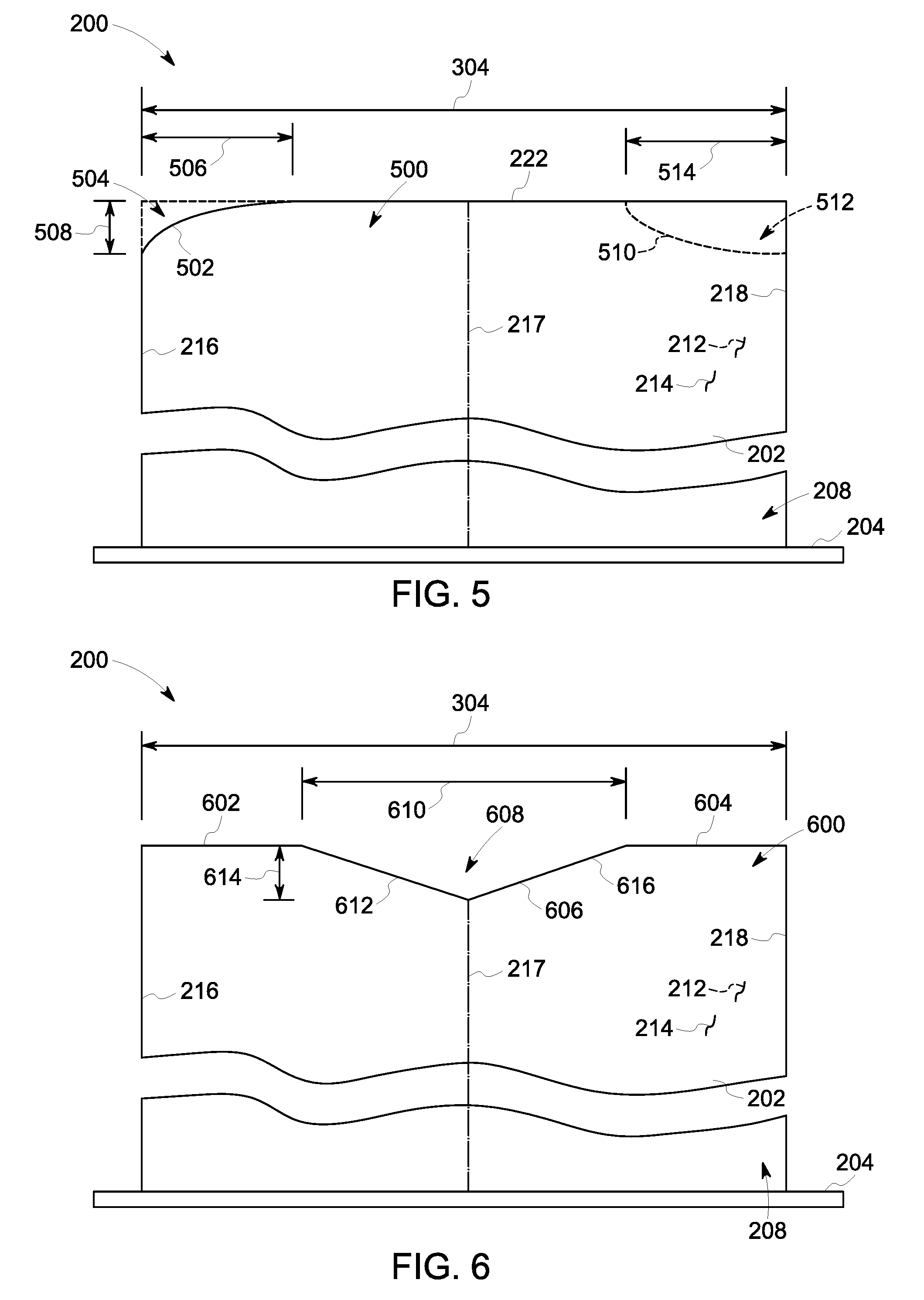
FIG. 5 is a schematic view of an alternative tip portion 500 for use with rotor blade 200 (shown in FIG. 2). In this alternative embodiment, rotor blade 200 includes pressure sidewall 212 and an opposing suction sidewall 214 which extend from root portion 208 to tip portion 500. Additionally, tip portion 500 includes planar section 222 that extends from pressure sidewall 212 to suction sidewall 214 and substantially perpendicular thereto. Further, tip portion 500 includes an oblique section 502 that convexly curves from planar section 222 inward towards root portion 208 to leading edge 216 forming a recess 504. Specifically, convex oblique section 502 extends a distance 506 along tip portion 500 from leading edge 216 approximately 30% of chord distance 304 of airfoil 202. Additionally, convex oblique section 502 extends a depth 508 from planar section 222. In alternative embodiments, convex oblique section 502 extends for any other distance 506 and/or depth 508 that enables rotor blade 200 to function as described herein.
Additionally, or alternatively, in this alternative embodiment, tip portion 500 includes oblique section 510 that concavely curves from planar section 222 inward towards root portion 208 to trailing edge 218 forming a recess 512. Specifically, concave oblique section 510 extends a distance 514 along tip portion 500 from trailing edge 218 approximately 30% of chord distance 304 of airfoil 202. Additionally, concave oblique section 510 extends for depth 508 from planar section 222. In alternative embodiments, concave oblique section 510 extends for any other distance 514 and/or depth 508 that enables rotor blade 200 to function as described herein. Further, in alternative embodiments, concave oblique section 510 is adjacent to leading edge 216 and/or convex oblique section 502 is adjacent to trailing edge 218.
Similar to tip portion 210 (shown in FIG. 3), tip portion 500 reduces the rub ratio of blade 200. Oblique section 502 and/or 510 lowers the contact force between rotor blade 200 and casing 106 (shown in FIG. 1) thereby reducing radial elongation. Reducing radial elongation within rotor blade 200 decreases the amount of material loss due to rubbing against casing 106 and thus wear of rotor blade 200.
FIG. 6 is a schematic view of another alternative tip portion 600 for use with rotor blade 200 (shown in FIG. 2). In this alternative embodiment, rotor blade 200 includes pressure sidewall 212 and an opposing suction sidewall 214 which extend from root portion 208 to tip portion 600. Additionally, tip portion 600 includes a first planar section 602 and a second planar section 604 that each extend from pressure sidewall 212 to suction sidewall 214 and substantially perpendicular thereto. Further, tip portion 600 includes an oblique section 606 forming a recess 608 between first and second planar sections 602 and 604. Specifically, oblique section 606 extends a distance 610 along tip portion 600 from first planar section 602 to second planar section 604 at approximately 40% of chord distance 304 of airfoil 202 centering about mid-chord line 217. Oblique section 606 has a first section 612 that extends from first planar section 602 to mid-chord line 217 at a depth 614 such that first section 612 slopes from first planar section 602 towards root portion 208 in a direction towards trailing edge 218. Oblique section 606 has a second section 616 that extends from second planar section 604 to mid-chord line 217 such that second section 616 slopes from second planar section 604 towards root portion 208 in a direction towards leading edge 216. In this alternative embodiment, oblique section 606 forms a V-shaped recess 608 about mid-chord line 217. In alternative embodiments, oblique section 606 extends for any other distance 610 and/or depth 614 that enables rotor blade 200 to function as described herein. Additionally, in alternative embodiments, oblique section 606 does not center about mid-chord line 217.
Similar to tip portion 210 (shown in FIG. 3), tip portion 600 reduces the rub ratio of blade 200. Oblique section 606 lowers the contact force between rotor blade 200 and casing 106 (shown in FIG. 1) thereby reducing radial elongation. Reducing radial elongation within rotor blade 200 decreases the amount of material loss due to rubbing against casing 106 and thus wear of rotor blade 200.
FIG. 7 is a schematic view of a further alternative tip portion 700 for use with rotor blade 200 (shown in FIG. 2). In this alternative embodiment, rotor blade 200 includes pressure sidewall 212 and an opposing suction sidewall 214 which extend from root portion 208 to tip portion 700. Additionally, tip portion 700 includes a first planar section 702 and a second planar section 704 that each extend from pressure sidewall 212 to suction sidewall 214 and substantially perpendicular thereto. Further, tip portion 700 includes an oblique section 706 forming a recess 708 between first and second planar sections 702 and 704. Specifically, oblique section 706 extends a distance 710 along tip portion 700 from first planar section 702 to second planar section 704 at approximately 40% of chord distance 304 of airfoil 202 centering about mid-chord line 217. Oblique section 706 has a first section 712 that extends from first planar section 702 to mid-chord line 217 at a depth 714 such that first section 712 concavely slopes from first planar section 602 towards root portion 208 in a direction towards trailing edge 218. Oblique section 706 has a second section 716 that extends from second planar section 704 to mid-chord line 217 such that second section 716 convexly slopes from second planar section 704 towards root portion 208 in a direction towards leading edge 216. In this alternative embodiment, oblique section 706 forms a U-shaped recess 708 about mid-chord line 217. In alternative embodiments, oblique section 706 extends for any other distance 710 and/or depth 714 that enables rotor blade 200 to function as described herein. Additionally, in alternative embodiments, oblique section 706 does not center about mid-chord line 217.
Similar to tip portion 210 (shown in FIG. 3), tip portion 700 reduces the rub ratio of blade 200. Oblique section 706 lowers the contact force between rotor blade 200 and casing 106 (shown in FIG. 1) thereby reducing radial elongation. Reducing radial elongation within rotor blade 200 decreases the amount of material loss due to rubbing against casing 106 and thus wear of rotor blade 200.
The above described rotor blade tip geometries reduces wear in a turbomachine. Specifically, a rotor blade includes an airfoil having a suction sidewall coupled to a pressure sidewall at a leading edge and a trailing edge. A tip portion extends between the suction sidewall and the pressure sidewall and includes a planar section and an oblique section. In some embodiments, the tip portion includes a first oblique section and a second oblique section. Modifying the rotor blade tip geometry by grinding the tip portion and forming the oblique section reduces the rub ratio of the rotor blade and, thereby, the wear of the rotor blade. Specifically, the oblique section is sized such that a contact area between the rotor blade and a surrounding casing is reduced, thereby decreasing the radial and tangential loads induced into the rotor blade during a rub event. Reducing the loads resulting from a rub event decreases vibration and deflection of the rotor blade and reduces material loss at the tip portion. Furthermore, modifying the rotor blade tip geometry changes the vibratory modes of the rotor blade such that radial elongation is decreased further reducing material loss at the tip portion. Additionally, a reduction in radial deflection allows the rotor blade to be positioned closer to the surrounding casing. Accordingly, decreasing the rub ratio of the rotor blade decreases wear and material loss during a rub event, increases turbomachine performance, and reduces maintenance costs.
An exemplary technical effect of the methods, systems, and apparatus described herein includes at least one of the following: (a) decreasing material loss of the rotor blade tip during a rub event with a surrounding casing; (b) reducing wear of the rotor blade; (b) decreasing a clearance gap between the rotor blade and the casing; (c) reducing maintenance costs of turbomachines; and (d) increasing turbomachine performance.
Exemplary embodiments of methods, systems, and apparatus for reducing rotor blade tip wear are not limited to the specific embodiments described herein, but rather, components of systems and/or steps of the methods may be utilized independently and separately from other components and/or steps described herein. Further, the methods, systems, and apparatus may also be used in combination with other systems requiring decreasing wear from a rub event, and the associated methods are not limited to practice with only the systems and methods described herein. Rather, the exemplary embodiment can be implemented and utilized in connection with many other applications, equipment, and systems that may benefit from reducing wear on a blade tip.
Although specific features of various embodiments of the disclosure may be shown in some drawings and not in others, this is for convenience only. In accordance with the principles of the disclosure, any feature of a drawing may be referenced and/or claimed in combination with any feature of any other drawing.
This written description uses examples to disclose the embodiments, including the best mode, and also to enable any person skilled in the art to practice the embodiments, including making and using any devices or systems and performing any incorporated methods. The patentable scope of the disclosure is defined by the claims, and may include other examples that occur to those skilled in the art. Such other examples are intended to be within the scope of the claims if they have structural elements that do not differ from the literal language of the claims, or if they include equivalent structural elements with insubstantial differences from the literal language of the claims.
* * * * *
D00000
D00001
D00002
D00003
D00004
D00005
XML
uspto.report is an independent third-party trademark research tool that is not affiliated, endorsed, or sponsored by the United States Patent and Trademark Office (USPTO) or any other governmental organization. The information provided by uspto.report is based on publicly available data at the time of writing and is intended for informational purposes only.
While we strive to provide accurate and up-to-date information, we do not guarantee the accuracy, completeness, reliability, or suitability of the information displayed on this site. The use of this site is at your own risk. Any reliance you place on such information is therefore strictly at your own risk.
All official trademark data, including owner information, should be verified by visiting the official USPTO website at www.uspto.gov. This site is not intended to replace professional legal advice and should not be used as a substitute for consulting with a legal professional who is knowledgeable about trademark law.