Downhole wellbore high power laser heating and fracturing stimulation and methods
Batarseh A
U.S. patent number 10,385,668 [Application Number 15/373,070] was granted by the patent office on 2019-08-20 for downhole wellbore high power laser heating and fracturing stimulation and methods. This patent grant is currently assigned to SAUDI ARABIAN OIL COMPANY. The grantee listed for this patent is Saudi Arabian Oil Company. Invention is credited to Sameeh Issa Batarseh.


| United States Patent | 10,385,668 |
| Batarseh | August 20, 2019 |
Downhole wellbore high power laser heating and fracturing stimulation and methods
Abstract
A system for fracturing a formation comprising a laser surface unit configured to generate a laser beam, a power cable electrically connected to a power source, a fluid line connected to a cooling fluid source, a protective shaft extending into the wellbore, the motor configured to rotate a motor shaft, and the thermal shocking tool comprising a protective case, a rotational shaft connected to the motor shaft, the laser delivery device extending from the rotational shaft configured to transform the laser beam to a focused laser beam operable to increase the temperature of the formation to a fracture temperature, and the cooling system extending from the rotational shaft opposite the laser delivery device configured to introduce the cooling fluid stream onto the formation such that the cooling fluid stream reduces the temperature of the formation such that thermal shocks occur and fractures are formed in the formation.
| Inventors: | Batarseh; Sameeh Issa (Dhahran Hills, SA) | ||||||||||
|---|---|---|---|---|---|---|---|---|---|---|---|
| Applicant: |
|
||||||||||
| Assignee: | SAUDI ARABIAN OIL COMPANY
(SA) |
||||||||||
| Family ID: | 60888627 | ||||||||||
| Appl. No.: | 15/373,070 | ||||||||||
| Filed: | December 8, 2016 |
Prior Publication Data
| Document Identifier | Publication Date | |
|---|---|---|
| US 20180163524 A1 | Jun 14, 2018 | |
| Current U.S. Class: | 1/1 |
| Current CPC Class: | E21B 36/001 (20130101); E21B 36/04 (20130101); E21B 47/00 (20130101); E21B 43/2405 (20130101); E21B 43/26 (20130101); E21B 43/114 (20130101); E21B 43/11 (20130101) |
| Current International Class: | E21B 43/24 (20060101); E21B 47/00 (20120101); E21B 36/04 (20060101); E21B 36/00 (20060101); E21B 43/114 (20060101); E21B 43/11 (20060101); E21B 43/26 (20060101) |
References Cited [Referenced By]
U.S. Patent Documents
| 2548463 | April 1951 | Blood |
| 3977478 | August 1976 | Shuck |
| 4090572 | May 1978 | Welch |
| 4227582 | October 1980 | Price |
| 4282940 | August 1981 | Salisbury et al. |
| 6870128 | March 2005 | Kobayashi et al. |
| 6880646 | April 2005 | Batarseh |
| 6888097 | May 2005 | Batarseh |
| 7086484 | August 2006 | Smith |
| 7490664 | February 2009 | Skinner et al. |
| 8235140 | August 2012 | Wideman |
| 8967293 | March 2015 | Von Rohr |
| 9338667 | May 2016 | Ma |
| 2004/0206505 | October 2004 | Batarseh |
| 2006/0102343 | May 2006 | Skinner et al. |
| 2007/0267220 | November 2007 | Magiawala et al. |
| 2010/0044102 | February 2010 | Rinzler et al. |
| 2010/0089576 | April 2010 | Wideman |
| 2012/0074110 | March 2012 | Zediker et al. |
| 2012/0118568 | May 2012 | Kleefisch et al. |
| 2012/0267168 | October 2012 | Grubb |
| 2013/0008659 | January 2013 | Schultz et al. |
| 2013/0228372 | September 2013 | Linyaev et al. |
| 2014/0041940 | February 2014 | Shnell |
| 2014/0216728 | August 2014 | Kosakewich |
| 2014/0360778 | December 2014 | Batarseh |
| 2015/0345225 | December 2015 | Kocis |
| 2016/0158880 | June 2016 | Koitzsch |
| 2016/0160618 | June 2016 | Batarseh |
| 2420135 | May 2006 | GB | |||
| 20040009958 | Jan 2004 | WO | |||
| 2016090229 | Jun 2016 | WO | |||
| 2016186690 | Nov 2016 | WO | |||
Other References
|
PCT/US2014/036553 International Search Report and Written Opionion dated Feb. 18, 2015; 11 pgs. cited by applicant . PCT/US2017/065003 International Search Report and Written Opionion dated Apr. 5, 2018; 15 pgs. cited by applicant . Batarseh et al."Well Perforation Using High-Power Lasers" SPE Annual Technical Conference and Exhibition, SPE 84418, Denver, Colorado, Oct. 5-8, 2003, 10 pages. cited by applicant . Anonymous"Laser Applications Laboratory--Laser Oil & Gas Well Drilling" Argonne National Laboratory, Nuclear Engineering Division, http://www.ne.anl.gov/facilities/lal/laser_drilling.html, printed Feb. 5, 2013, 2 pages. cited by applicant . Bakhtbidar et al."Application of Laser Technology for Oil and Gas Wells Perforation" SPE/IADC Middle East Drilling Technology Conference and Exhibition, SPE/IADC 148570, Muscat, Oman, Oct. 24-26, 2011, 12 pages. cited by applicant . Batarseh et al."Deep hole penetration of rock for oil production using Ytterbium fiber laser" SPIE Proceedings, Conference vol. 5448, High-Power Laser Ablation V, 818, Taos, New Mexico, Sep. 20, 2004, 9 pages. cited by applicant . Batarseh et al."Innovation in Wellbore Perforation Using High-Power Laser" International Petroleum Technology Conference, IPTC 10981, Doha, Qatar, Nov. 21-23, 2005, 7 pages. cited by applicant . Yaseen, et al. "The Geo-Materials Fracture by Thermal Process", Proceedings, Thirty-Ninth Workshop on Geothermal Reservoir Engineering Stanford University, Stanford, California, Feb. 24-26, 2014, SGP-TR-202, XP 55460344A, pp. 1-7. cited by applicant. |
Primary Examiner: Gray; George S
Attorney, Agent or Firm: Bracewell LLP Rhebergen; Constance G.
Claims
What is claimed is:
1. A system for fracturing a formation from a wellbore extending into the formation from a surface, the system comprising: a laser surface unit, the laser surface unit located on the surface, the laser surface unit configured to generate a laser beam; a fiber optic cable, the fiber optic cable optically connected to a laser delivery device of a thermal shocking tool, the fiber optic cable configured to transmit the laser beam to the laser delivery device to produce a focused laser beam; a power cable, the power cable electrically connected to a power source on the surface, the power cable configured to transmit electrical energy to a motor; a fluid line, the fluid line connected to a cooling fluid source on the surface, the fluid line configured to supply a cooling fluid to a cooling system of the thermal shocking tool to produce a cooling fluid stream; a protective shaft, the protective shaft extending into the wellbore, wherein the fiber optic cable, the power cable, and the fluid line are contained within the protective shaft; the motor, the motor configured to rotate a motor shaft; a purge nozzle, the purge nozzle positioned between the surface and the motor, where the purge nozzle is configured to keep debris from settling on the motor; and the thermal shocking tool physically connected to the motor, the thermal shocking tool comprising: a protective case, the protective case configured to encompass the laser delivery device and the cooling system, a rotational shaft, the rotational shaft connected to the motor shaft such that as the motor shaft rotates the rotational shaft rotates, the laser delivery device extending from the rotational shaft, the laser delivery device configured to transform the laser beam to a focused laser beam, wherein the focused laser beam is operable to increase the temperature of the formation to a fracture temperature, and the cooling system, the cooling system extending from the rotational shaft opposite the laser delivery device, the cooling system comprising one or more cooling nozzles extending through the protective case such that the one or more cooling nozzles are configured to introduce the cooling fluid stream onto the formation such that the cooling fluid stream reduces the temperature of the formation, wherein the laser delivery device and the cooling system rotate around the wellbore as the rotational shaft rotates, wherein rotation of the rotational shaft is configured to alternate between increasing the temperature of the formation and reducing the temperature of the formation such that thermal shocks occur and fractures are formed in the formation.
2. The system of claim 1, wherein the cooling fluid is selected from the group consisting of nitrogen gas, liquid nitrogen, helium, air, carbon dioxide, and water.
3. The system of claim 1, wherein the fracture temperature is 2000 deg. C.
4. The system of claim 1 further comprising an acoustic capability, wherein the acoustic capability is configured to monitor and record a fracturing sound due to the thermal shocking tool, wherein the acoustic capability is selected from the group consisting of transducers, geophones, and combinations of the same.
5. The system of claim 1, wherein the laser delivery device is positioned to introduce the focused laser beam to the formation at a pre-determined angle.
6. A method for fracturing a formation from a wellbore extending into the formation from a surface, the method comprising the steps of: introducing a focused laser beam to the formation such that the focused laser beam is operable to increase the temperature of the formation to a fracture temperature, wherein the focused laser beam is produced by a laser delivery device, the laser delivery device extending from a rotational shaft; introducing a cooling fluid stream to the formation such that the cooling fluid stream is operable to reduce the temperature of the formation, wherein the cooling fluid stream is produced by a cooling system, the cooling system device extending from the rotational shaft opposite from the laser delivery device; rotating the rotational shaft such that the formation is alternately introduced to the focused laser beam and the cooling fluid such that thermal shocks occur and fractures in the formation are formed; transmitting electrical energy from a power source to a motor through a power cable; transforming the electrical energy to mechanical energy in the motor, such that the mechanical energy rotates a motor shaft, wherein the motor shaft is connected to the rotational shaft such that as the motor shaft rotates the rotational shaft rotates; and introducing a fluid through a purge nozzle positioned between the surface and the motor, where the purge nozzle is configured to keep debris from settling on the motor.
7. The method of claim 6, further comprising the steps of: generating a laser beam in a laser surface unit; and transmitting the laser beam from the laser surface unit to the laser delivery device through a fiber optic cable.
8. The method of claim 6, wherein the cooling fluid is selected from the group consisting of nitrogen gas, liquid nitrogen, helium, air, carbon dioxide, and water.
9. The method of claim 6, wherein the fracture temperature is 2000 deg. C.
10. The method of claim 6 further comprising the step of measuring by an acoustic capability fracturing sound due to the thermal shocking tools, wherein the acoustic capability is selected from the group consisting of transducers, geophones, and combinations of the same.
11. The method of claim 6, wherein the laser delivery device is positioned to introduce the focused laser beam to the formation at a pre-determined angle.
Description
TECHNICAL FIELD
Disclosed are apparatus and methods for wellbore stimulation. More specifically, embodiments related to apparatus and methods that incorporate lasers for wellbore stimulation applications.
BACKGROUND
Methods for stimulating a wellbore aim to provide a pathway for fluids to flow from the formation to the wellbore. Hydraulic fracturing is one method for stimulating a wellbore. Conventional hydraulic fracturing injects water at high pressure into the wellbore, which causes fractures of the formation. In conventional hydraulic fracturing, an explosive charge is used to perforate the casing and cementing. An explosive charge is a high impact technology that can cause compaction, deformation of the hole, and sanding and crushing the grains of the rock material. The crushed grains of rock material can be pushed into the formation, blocking the formation and reducing production.
Additionally, the use of water in conventional hydraulic fracturing is incompatible with certain types of formation, such as shale. Water in shale can cause clay swelling, which blocks flow from the formation to the wellbore.
SUMMARY
Disclosed are apparatus and methods for wellbore stimulation. More specifically, embodiments related to apparatus and methods that incorporate lasers for wellbore stimulation applications.
In a first aspect, a system for fracturing a formation from a wellbore extending into the formation from a surface is provided. The system includes a laser surface unit located on the surface, the laser surface unit configured to generate a laser beam, a fiber optic cable optically connected to a laser delivery device of a thermal shocking tool, the fiber optic cable configured to transmit the laser beam to the laser delivery device to produce a focused laser beam, a power cable electrically connected to a power source on the surface, the power cable configured to transmit electrical energy to a motor, a fluid line connected to a cooling fluid source on the surface, the fluid line configured to supply a cooling fluid to a cooling system of the thermal shocking tool to produce a cooling fluid stream, a protective shaft extending into the wellbore, wherein the fiber optic cable, the power cable, and the fluid line are contained within the protective shaft, the motor configured to rotate a motor shaft, and the thermal shocking tool physically connected to the motor. The thermal shocking tool includes a protective case configured to encompass the laser delivery device and the cooling system, a rotational shaft connected to the motor shaft such that as the motor shaft rotates the rotational shaft rotates, the laser delivery device extending from the rotational shaft, the laser delivery device configured to transform the laser beam to a focused laser beam, wherein the focused laser beam is operable to increase the temperature of the formation to a fracture temperature, and the cooling system extending from the rotational shaft opposite the laser delivery device, the cooling system comprising one or more cooling nozzles extending through the protective case such that the one or more cooling nozzles are configured to introduce the cooling fluid stream onto the formation such that the cooling fluid stream reduces the temperature of the formation, where the laser delivery device and the cooling system rotate around the wellbore as the rotational shaft rotates, where rotation of the rotational shaft is configured to alternate between increasing the temperature of the formation and reducing the temperature of the formation such that thermal shocks occur and fractures are formed in the formation.
In certain aspects, the system further includes a purge nozzle, the purge nozzle positioned between the surface and the motor, where the purge nozzle is configured to keep debris from settling on the motor. In certain aspects, the cooling fluid is selected from the group consisting of nitrogen gas, liquid nitrogen, helium, air, carbon dioxide, and water. In certain aspects, the fracture temperature is 2000 deg. C. In certain aspects, the system further includes an acoustic capability. In certain aspects, the focused laser beam can increase the temperature of the formation to the fracture temperature in less than 1 second. In certain aspects, the laser delivery device can be positioned to introduce the focused laser beam to the formation at a pre-determined angle.
In a second aspect, a method for fracturing a formation from a wellbore extending into the formation from a surface is provided. The method includes the steps of introducing a focused laser beam to the formation such that the focused laser beam is operable to increase the temperature of the formation to a fracture temperature. The focused laser beam is produced by a laser delivery device extending from a rotational shaft. The method further includes a step of introducing a cooling fluid stream to the formation such that the cooling fluid stream is operable to reduce the temperature of the formation, where the cooling fluid stream is produced by a cooling system. The cooling system device extending from the rotational shaft opposite from the laser delivery device; and rotating the rotational shaft such that the formation is alternately introduced to the focused laser beam and the cooling fluid such that thermal shocks occur and fractures in the formation are formed.
In certain aspects, the method further includes the steps of generating a laser beam in a laser surface unit, and transmitting the laser beam from the laser surface unit to the laser delivery device through a fiber optic cable. In certain aspects, the method further includes the steps of transmitting electrical energy from a power source to a motor through a power cable, and transforming the electrical energy to mechanical energy in the motor, such that the mechanical energy rotates a motor shaft, wherein the motor shaft is connected to the rotational shaft such that as the motor shaft rotates the rotational shaft rotates. In certain aspects, the method further includes the step of measuring the sound emitted by an acoustic capability.
BRIEF DESCRIPTION OF THE DRAWINGS
These and other features, aspects, and advantages will become better understood with regard to the following descriptions, claims, and accompanying drawings. It is to be noted, however, that the drawings illustrate only several embodiments and are therefore not to be considered limiting of the inventive scope as it can admit to other equally effective embodiments.
FIG. 1 is a plan view of an embodiment of the laser fracturing tool.
FIG. 2 is a plan view of the laser fracturing tool including the motor and the thermal shocking tool.
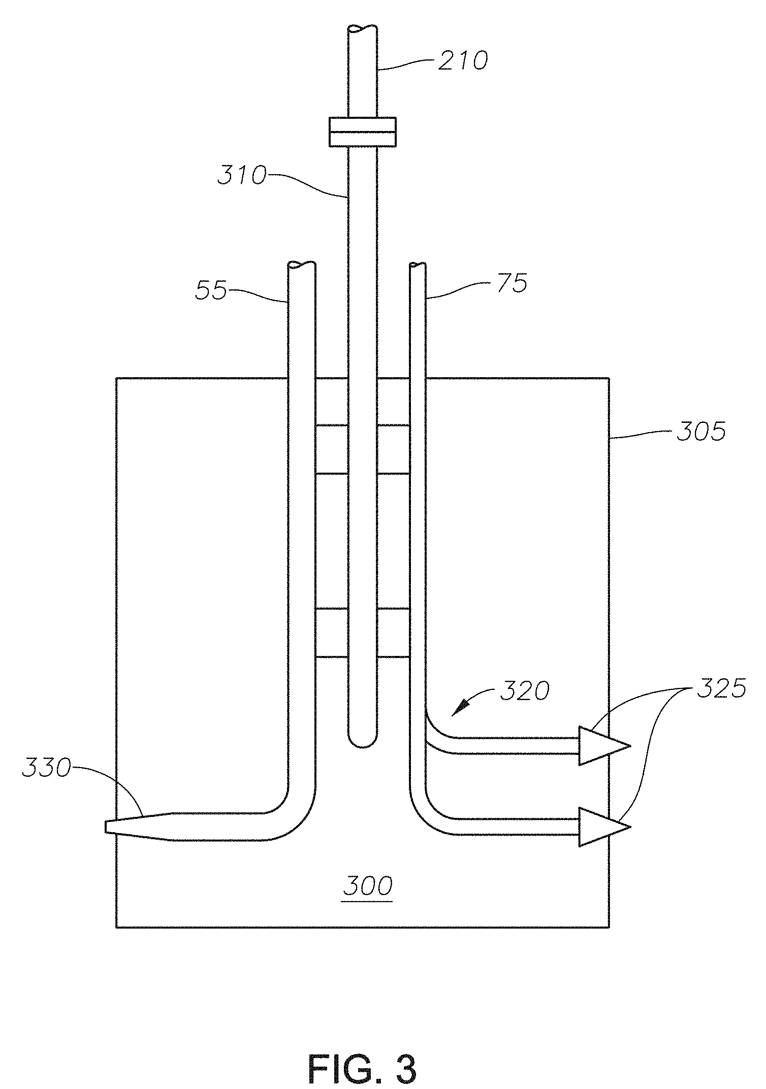
FIG. 3 is a plan view of an embodiment of the thermal shocking tool.
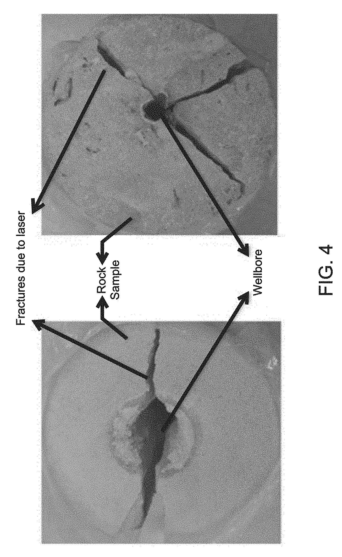
FIG. 4 is a pictorial representation of core samples fractured by laser.
DETAILED DESCRIPTION
While the scope will be described with several embodiments, it is understood that one of ordinary skill in the relevant art will appreciate that many examples, variations and alterations to the apparatus and methods described are within the scope and spirit of the embodiments. Accordingly, the embodiments described here are set forth without any loss of generality, and without imposing limitations. Those of skill in the art understand that the inventive scope includes all possible combinations and uses of particular features described in the specification. In both the drawings and the detailed description, like numbers refer to like elements throughout.
Described are an apparatus and methods for fracturing a formation with a laser fracturing tool. The laser fracturing tool can be used to establish fluid communication between the wellbore and the formation to improve production of formation fluids. Advantageously, the laser fracturing tool can provide a targeted method of fracturing the formation as compared to a conventional hydraulic fracturing. The laser fracturing tool can be used to target the location of the fracture, such as targeting the angle and depth of the fracture. In addition, the laser can be located along fault lines. Advantageously, the rotation of the laser fracturing tool means the method of fracturing can be implemented around the entire circumference of the wellbore without the need to reposition the tool. Advantageously, the laser fracturing tool in the absence of a hydraulic fracturing step. The absence of hydraulic fracturing has environmental advantages as hydraulic fracturing consumes and pollutes large quantities of water. The laser fracturing tool produces less damage to the rock material of a formation than conventional hydraulic fracturing.
FIG. 1 is an elevation view of laser fracturing tool 100. Laser fracturing tool 100 is deployed in wellbore 10 of formation 40. Surface 30 is the surface of the earth from which wellbore 10 extends. Wellbore 10 extends from surface 30 into formation 40. Formation 40 can be any type of formation composed of any type of rock material. In at least one embodiment, formation 40 contains limestone. In at least one embodiment, formation 40 contains sandstone. In at least one embodiment, formation 40 contains shale. Wellbore 10 can be finished with casing 20 and cement 25 for reinforcement.
Laser surface unit 50 can be located on surface 30 near wellbore 10. Laser surface unit 50 can be in optical communication with laser fracturing tool 100 via fiber optic cable 55. Laser surface unit 50 can be configured to excite energy to a level above the sublimation point of formation 40 to form a laser beam (not shown). The sublimation point of formation 40 can be determined based on the rock material contained in formation 40, where the rock material controls the sublimation point which then controls the excitation energy of the laser beam. In at least one embodiment, laser surface unit 50 can be tuned to excite energy to different excitation levels as can be required for different formations. Laser surface unit 50 can by any type of laser unit capable of generating a laser beam and introducing said laser beam into a fiber optic cable. Examples of laser surface unit 50 include lasers of ytterbium, erbium, neodymium, dysprosium, praseodymium, and thulium ions. In at least one embodiment, laser surface unit 50 can be a 5.34-kW ytterbium doped multiclad fiber laser.
Fiber optic cable 55 can be any cable containing an optical fiber capable of transmitting a laser beam from laser surface unit 50 to laser fracturing tool 100. Fiber optic cable 55 can include one or more optical fibers. In an alternate embodiment, one or more fiber optic cables can provide electrical communication between laser surface unit 50 and laser fracturing tool 100. In at least one embodiment, fiber optic cable 55 provides a path for light from laser surface unit 50 to laser fracturing tool 100. In at least one embodiment, fiber optic cable 55 can conduct a raw laser beam from laser surface unit 50 to laser fracturing tool 100. A "raw laser beam" as used herein refers to a laser beam that has not been passed through lenses or otherwise focused.
Power source 60 can be located on surface 30 near wellbore 10. Power source 60 can be in electrical communication with laser fracturing tool 100 via power cable 65. Power source 60 can be any apparatus capable of generating electrical energy. Power cable 65 can be any type of cable capable of transmitting electrical energy to laser fracturing tool 100.
Cooling fluid source 70 can be located on surface 30 near wellbore 10 and can provide a cooling fluid to laser fracturing tool 100. Cooling fluid source 70 is in fluid communication with laser fracturing tool 100 via fluid line 75, such that the cooling fluid is delivered to laser fracturing tool 100 from cooling fluid source 70. Fluid line 75 can be any type of tube capable of supplying a fluid to laser fracturing tool 100. The cooling fluid can include nitrogen gas, liquid nitrogen, helium, air, carbon dioxide, and water. The cooling fluid can be selected based on the rock material of formation 40 and the thermal properties of the rock material. The temperature gradient desired between the fracture temperature and the cooled temperature, the rotation period of the thermal shocking tool, and the efficiency of the cooling fluid in reducing the temperature of the rock material. In at least one embodiment, one or more fluid lines 75 can be in fluid communication with cooling fluid source 70 and laser fracturing tool 100.
Fiber optic cable 55, power cable 65, and fluid line 75 can be encompassed in protective shaft 80. Protective shaft 80 can be any material of construction suitable for use in a downhole environment without experiencing mechanical or chemical failure. As used here, "downhole environment" refers to the high operating pressure, high operating temperature, and fluid conditions that can be found in a wellbore extending into a formation.
FIG. 2 is a section view in elevation of one embodiment of laser fracturing tool 100 as understood with reference to FIG. 1. Laser fracturing tool 100 includes motor 200 and thermal shocking tool 300. Power cable 65 is in electrical communication with motor 200, such that power cable 65 transmits electrical energy to motor 200. Motor 200 is physically connected to motor shaft 210. Motor 200 can be any motor capable of converting electrical energy transmitted by power cable 65 into mechanical energy to rotate motor shaft 210 in a downhole environment. Motor shaft 210 is physically connected to rotational shaft 310 of thermal shocking tool 300.
Fiber optic cable 55 is in optical communication with thermal shocking tool 300. Cooling fluid line 75 is in fluid communication with thermal shocking tool 300.
In at least one embodiment, purge nozzle 220 can be located between motor 200 and surface 30, such that purge nozzle 220 is configured to deliver a fluid to the wellbore. In at least one embodiment, purge nozzle 220 can be located between motor 200 and surface 30 near motor 200 such that purge nozzle 220 is operable to deliver the fluid near motor 200. In at least one embodiment, purge nozzle 220 delivers the fluid such that the fluid is operable to clean motor 200, such that the purge fluid from purge nozzle 220 can keep dust and debris from settling on motor 200. In at least one embodiment, purge nozzle 220 delivers the fluid such that the fluid is operable to direct the produced fluid in wellbore 10. As used here, "produced fluid" refers to the fluid that flows from the formation into the wellbore due to fracturing of the formation by laser fracturing tool 100. In at least one embodiment, one or more purge nozzles 220 can be configured in a purge nozzle configuration (not shown) such that the purge nozzle configuration is configured to deliver the fluid to multiple points in wellbore 10. The purge fluid can be any fluid capable of cleaning the motor and directing fluid. Examples of purge fluid can include air and nitrogen gas. The purge fluid can be at the ambient temperature of the purge fluid source (not shown). In an alternate embodiment, the purge fluid is from cooling fluid source 70.
FIG. 3 is a section view in elevation of a thermal shocking tool 300 with reference to features described in FIG. 2. Thermal shocking tool 300 includes protective case 305, rotational shaft 310, cooling system 320, and laser delivery device 330.
Protective case 305 surrounds rotational shaft 310, cooling system 320, and laser delivery device 330. Protective case 305 can be formed from any materials capable of withstanding the downhole environment without suffering mechanical failure. Cooling system 320 and laser delivery device 330 can extend into and through protective case 305.
Rotational shaft 310 connected to motor shaft 210 extends through protective case 305. Rotational shaft 310 rotates as motor shaft 210 rotates as driven by motor 200. Rotational shaft 310 provides an axis around which cooling system 320 and laser delivery device 330 rotate. Rotational shaft 310 can provide physical support, such as an anchor to cooling system 320 and laser delivery device 330. Cooling system 320 and laser delivery device 330 are mounted to rational shaft 310 such that cooling system 320 is opposite laser delivery device 330. As used herein, "opposite" refers to a position 180 degrees around the axis formed by rotational shaft 310, such that if cooling system 320 extends perpendicularly from rotational shaft 310 at zero (0) degrees, laser delivery device extends perpendicularly from rotational shaft 310 at one-hundred eighty (180) degrees. Rotational shaft 310 can be any material of construction suitable for use in a downhole environment that is rigid enough to provide physical support to cooling system 320 and laser delivery device 330.
Cooling system 320 can include one or more cooling nozzles 325 as shown in FIG. 3. Cooling nozzles 325 are fluidly connected to fluid line 75, such that the cooled purge fluid is delivered from cooling fluid source 70. Cooling system 320 can be configured to introduce the cooling fluid to formation 40 as a cooling fluid stream. The cooling fluid stream is operable to reduce the temperature formation 40.
Laser delivery device 330 is optically connected to fiber optic cable 55. Laser delivery device 330 can be configured to focus the laser beam from fiber optic cable 55 to produce a focused beam. In one embodiment, laser delivery device 330 can incorporate the features and details set forth in U.S. Pat. No. 9,217,291.
The focused laser beam is operable to increase the temperature of formation 40. The focused laser beam can be directed to sublimate the casing and the cement prior to contact formation 40. Advantageously, the focused laser beam can precisely cut the casing and the cement. The focused laser beam can increase the temperature of formation 40 in less than one second to a fracture temperature. The fracture temperature can reach 2,000 degrees Celsius (deg C.). The less than one second increase in temperature to the fracture temperature can cause thermal shocks in formation 40 which results in fractures, microfractures and cracks in the rock material of formation 40. As used here, "microfractures" refers to fractures in the range from a millimeter to a few centimeters that can be used for initiating fractures. As used here, "thermal shocks" refers to the expansion and contraction of the formation rock over a time period on the order of seconds. As thermal shocking tool 300 rotates, laser delivery device 330 continuously causes an increase in temperature of formation 40 around the wellbore. While laser delivery device 330 increases the temperature of formation 40, cooling system 320 decreases the temperature. The cooling fluid stream can be directed at formation 40, such that the cooling fluid stream can reduce the temperature of the formation to a cooled temperature. The cooled temperature depends on the fluid used as the cooling fluid stream.
The laser delivery device can include acoustic capability to monitor and record the fracturing sound due to the thermal shocking tool. Acoustic capability can include transducers or geophones. Fracturing sound can be used to indicate the fracture length and size. The acoustic capability can be placed above the motor, below the thermal shocking tool, or both above the motor and below the thermal shocking tool. Power can be supplied to the acoustic capability from power source 60 (not shown). The acoustic capability can transmit the measurements directly to the surface or can be stored and retrieved after the laser fracturing.
EXAMPLE
Example 1
A dry core sample measuring 2''.times.2'' of Berea and limestone was obtained. A 3 kW power laser was used to produce a continuous laser beam of 0.35 inches. The laser beam was turned on for four (4) seconds before being switched off. Fractures immediately formed in the core sample. Air, at room temperature, was used as the cooling fluid stream on one side of the core sample to orient the fractures. As can be seen in FIG. 4, fractures formed in the core sample.
Although the technology has been described in detail, it should be understood that various changes, substitutions, and alterations can be made hereupon without departing from the inventive principle and scope. Accordingly, the scope of the embodiments should be determined by the following claims and their appropriate legal equivalents.
The singular forms "a," "an," and "the" include plural referents, unless the context clearly dictates otherwise.
Optional or optionally means that the subsequently described event or circumstances can or may not occur. The description includes instances where the event or circumstance occurs and instances where it does not occur.
Ranges may be expressed as from one particular value to another particular value. When such a range is expressed, it is to be understood that another embodiment is from the one particular value to the other particular value, along with all combinations within said range.
Throughout this application, where patents or publications are referenced, the disclosures of these references in their entireties are intended to be incorporated by reference into this application, in order to more fully describe the state of the art, except when these references contradict the statements made here.
As used here and in the appended claims, the words "comprise," "has," and "include" and all grammatical variations thereof are each intended to have an open, non-limiting meaning that does not exclude additional elements or steps.
* * * * *
References
D00000
D00001
D00002
D00003
D00004
XML
uspto.report is an independent third-party trademark research tool that is not affiliated, endorsed, or sponsored by the United States Patent and Trademark Office (USPTO) or any other governmental organization. The information provided by uspto.report is based on publicly available data at the time of writing and is intended for informational purposes only.
While we strive to provide accurate and up-to-date information, we do not guarantee the accuracy, completeness, reliability, or suitability of the information displayed on this site. The use of this site is at your own risk. Any reliance you place on such information is therefore strictly at your own risk.
All official trademark data, including owner information, should be verified by visiting the official USPTO website at www.uspto.gov. This site is not intended to replace professional legal advice and should not be used as a substitute for consulting with a legal professional who is knowledgeable about trademark law.