Method and system for generating auxiliary power in an aircraft
Rideau A
U.S. patent number 10,384,799 [Application Number 15/032,782] was granted by the patent office on 2019-08-20 for method and system for generating auxiliary power in an aircraft. This patent grant is currently assigned to SAFRAN POWER UNITS. The grantee listed for this patent is Microturbo. Invention is credited to Jean-Francois Rideau.


| United States Patent | 10,384,799 |
| Rideau | August 20, 2019 |
Method and system for generating auxiliary power in an aircraft
Abstract
The invention concerns a method for generating auxiliary power in an aircraft, comprising the step consisting of: starting up an auxiliary power unit (6) of the aircraft by supplying compressed air to the auxiliary power unit (6) from a supercharger (7), and transferring non-propulsive energy from the auxiliary power unit (6) to the aircraft. The invention also concerns a system (5) for generating auxiliary power in an aircraft and an aircraft implementing such a method.
| Inventors: | Rideau; Jean-Francois (Tournefeuille, FR) | ||||||||||
|---|---|---|---|---|---|---|---|---|---|---|---|
| Applicant: |
|
||||||||||
| Assignee: | SAFRAN POWER UNITS (Toulouse,
FR) |
||||||||||
| Family ID: | 49998462 | ||||||||||
| Appl. No.: | 15/032,782 | ||||||||||
| Filed: | October 29, 2014 | ||||||||||
| PCT Filed: | October 29, 2014 | ||||||||||
| PCT No.: | PCT/FR2014/052748 | ||||||||||
| 371(c)(1),(2),(4) Date: | April 28, 2016 | ||||||||||
| PCT Pub. No.: | WO2015/063414 | ||||||||||
| PCT Pub. Date: | May 07, 2015 |
Prior Publication Data
| Document Identifier | Publication Date | |
|---|---|---|
| US 20160264252 A1 | Sep 15, 2016 | |
Foreign Application Priority Data
| Oct 31, 2013 [FR] | 13 60732 | |||
| Current U.S. Class: | 1/1 |
| Current CPC Class: | B64D 41/00 (20130101); F04C 18/0215 (20130101); F01D 19/00 (20130101); F04C 23/02 (20130101); F04B 35/06 (20130101); F02C 7/32 (20130101); F04C 18/16 (20130101); F02C 7/26 (20130101); F05D 2220/50 (20130101); B64D 2041/002 (20130101) |
| Current International Class: | B64D 41/00 (20060101); F04C 18/02 (20060101); F02C 7/26 (20060101); F04B 35/06 (20060101); F02C 7/32 (20060101); F04C 23/02 (20060101); F04C 18/16 (20060101); F01D 19/00 (20060101) |
References Cited [Referenced By]
U.S. Patent Documents
| 2941790 | June 1960 | Compton et al. |
| 4642997 | February 1987 | Krafka |
| 5201798 | April 1993 | Hogan |
| 5309708 | May 1994 | Stewart, Jr. |
| 5343778 | September 1994 | Romero |
| 5555722 | September 1996 | Mehr-Ayin |
| 5845479 | December 1998 | Nakhamkin et al. |
| 6247668 | June 2001 | Reysa |
| 6651929 | November 2003 | Dionne |
| 6735951 | May 2004 | Thompson |
| 6941760 | September 2005 | Jones |
| 6942181 | September 2005 | Dionne |
| 7364117 | April 2008 | Dionne |
| 9644538 | May 2017 | Dionne |
| 2008/0245062 | October 2008 | Dionne |
| 2010/0293961 | November 2010 | Tong et al. |
| 2012/0180498 | July 2012 | Francisco |
| 2014/0130510 | May 2014 | Bouldin |
| 2014/0182306 | July 2014 | Castagnera |
| 2014/0360547 | December 2014 | Ribarov |
| 2015/0367952 | December 2015 | Rideau |
| 2554482 | Feb 2013 | EP | |||
| 2020367 | Nov 1974 | GB | |||
Other References
|
International Search Report and Written Opinion with English Language Translation, dated Apr. 2, 2015, Application No. PCT/FR2014/052748. cited by applicant . French Search Report and Written Opinion, dated Aug. 25, 2014, French Application No. 1360732. cited by applicant. |
Primary Examiner: Bonzell; Philip J
Attorney, Agent or Firm: Womble Bond Dickinson (US) LLP
Claims
The invention claimed is:
1. A method for generating auxiliary power in an aircraft, comprising: starting a volumetric compressor via a starter generator, starting an auxiliary power unit of the aircraft by supplying compressed air to the auxiliary power unit from the volumetric compressor, and transferring non-propulsive energy from the auxiliary power unit to the aircraft.
2. The method according to claim 1, wherein starting the auxiliary power unit includes supplying the auxiliary power unit with air coming only from the volumetric compressor.
3. The method according to claim 1, including the step, during a transitional phase, supply the auxiliary power unit with air coming from the volumetric compressor and ambient air.
4. The method according to claim 1, including the subsequent step of supplying the auxiliary power unit only with ambient air.
5. A system for generating auxiliary power in an aircraft, including: an auxiliary power unit, including an air inlet, and being configured to supply non-propulsive energy to the aircraft supplementing or replacing the main engines of the aircraft, a volumetric compressor connected to the air inlet of the auxiliary power unit, the volumetric compressor being configured to supply compressed air at the inlet of the auxiliary power unit, for starting said unit, and a starter generator, configured to drive the volumetric compressor and the auxiliary power unit.
6. The system according to claim 5, wherein the volumetric compressor includes a decoupling tool configured to decouple the volumetric compressor of a shaft of the auxiliary power unit.
7. The system according to claim 5, including a valve for controlling the flow rate between an air exhaust of the compressor and the air inlet of the auxiliary power unit.
8. The system according to claim 5, wherein the volumetric compressor has: an output air flow rate comprised between 0.1 and 0.2 kgs.sup.-1, a rotation speed of the mechanism less than 10,000 rpm, power great than or equal to 15 kW, and a compression rate comprised between 5 and 10 bars.
9. An aircraft including a system for generating auxiliary power according to claim 5.
Description
FIELD OF INVENTION
The invention relates to a method and a system for generating auxiliary power in an aircraft.
PRESENTATION OF THE PRIOR ART
Certain aircraft, such as commercial or regional airplanes, are equipped with main engines serving for propulsion, and an auxiliary power unit (APU) including a gas turbine and designed to supply non-propulsive energy on the ground and in flight when the main engine(s) are not able to do so.
Certain aircraft certifications, like the ETOPS certification (Extended Range Twin Engine Operation Performance Standards) require a cold-start capacity of the auxiliary power unit at very high altitude (between 39,000 and 41,000 ft depending on the carriers).
The tendency is to increase this ceiling, with restarting requirements of the auxiliary power unit 6 at 43,000 ft, or even 45,000 ft.
At these altitudes, however, the density of the ambient air is low, the outside temperature is low and the quantity of fuel needed for starting is low and difficult to measure out.
The starting of the auxiliary power unit then becomes difficult and requires long and costly development phases.
In addition, it is difficult to maintain a starting window for a sufficient period of time to start the gas turbine of the auxiliary power unit.
Finally, the higher the altitude of the aircraft, the narrower is the starting window, and thus the more difficult to detect and maintain.
PRESENTATION OF THE INVENTION
The invention proposes a method for generating auxiliary power in an aircraft, including the steps consisting of starting an auxiliary power unit of the aircraft by supplying compressed air to the auxiliary power unit from a positive-displacement compressor, and transferring non-propulsive energy from the auxiliary power unit to the aircraft.
The invention is advantageously supplemented by the following features, taken alone or in any one of their technically possible combinations: starting the auxiliary unit includes supplying the auxiliary power unit with air coming only from the positive-displacement compressor; during a transitional phase, supplying the auxiliary power unit with air coming from the volumetric compressor and from the ambient air; during a subsequent step, supplying the auxiliary power unit only with ambient air.
The invention further relates to a system for generating auxiliary power in an aircraft, including an aircraft auxiliary power unit, including an air inlet, and being configured to supply non-propulsive energy to the aircraft to supplement or replace the main engines of the aircraft, and a volumetric compressor connected to the air inlet of the auxiliary power unit, the volumetric compressor being configured to supply compressed air at the inlet of the auxiliary power unit for starting said unit.
This system is advantageously supplemented by the following features, taken alone or in any of their technically possible combinations: the system includes a starter generator, configured to drive the volumetric compressor and the auxiliary power unit; the system includes a decoupling tool configured to decouple the volumetric compressor from a shaft of the auxiliary power unit; the system includes a valve for controlling flow between an air exhaust of the compressor and the air inlet of the auxiliary power unit; the volumetric compressor has an air flow rate comprised between 0.1 and 0.2 kgs.sup.-1, a rotation speed less than 10,000 rpm, power greater than or equal to 15 kW and a compression rate comprised between 5 and 10 bars.
The invention also relates to an aircraft including this system.
The invention offers numerous advantages.
The invention makes it possible to start the auxiliary power unit in an effective and controlled manner, even at very high altitudes. In addition, starting is faster and less costly that the systems of the prior art.
PRESENTATION OF THE FIGURES
Other characteristics and advantages of the invention will still be revealed by the description that follows, which is purely illustrative and not limiting, and must be read with reference to the appended drawings wherein:
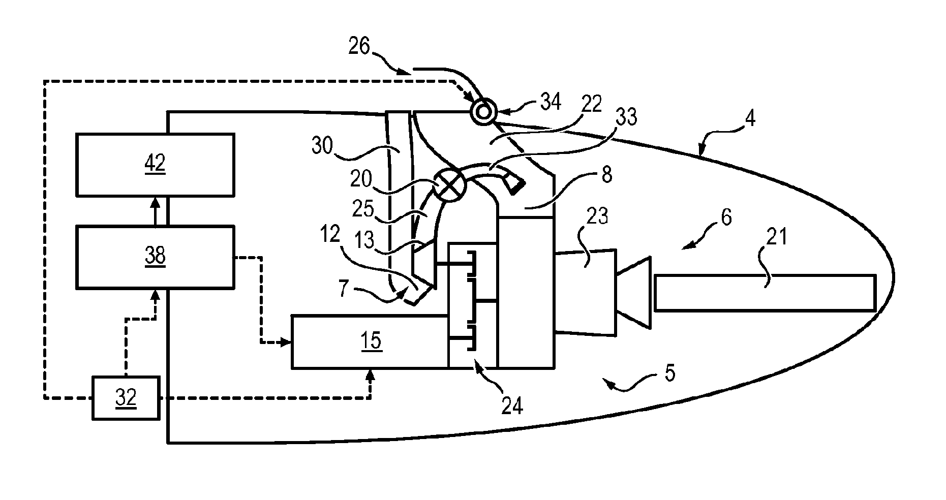
FIG. 1 shows schematically the tail of an airplane including an auxiliary power generation system;
FIG. 2 shows an example of the screw-type positive-displacement compressor;
FIG. 3 shows an example of a scroll type positive-displacement compressor;
FIG. 4 shows a starter generator connected to a volumetric compressor through an accessory box;
FIG. 5 shows the steps in a method for generating auxiliary power in an aircraft.
DETAILED DESCRIPTION
System for Generating Auxiliary Power
FIG. 1 shows schematically a system 5 for generating auxiliary power for an aircraft. This system 5 is conventionally positioned at the tail 4 at the rear of the aircraft.
The system 5 includes an auxiliary power unit 6. The unit 6 conventionally includes a gas turbine 23, an air inlet 8 and an exhaust 21. The auxiliary power unit 6 is configured to supply non-propulsive energy to the aircraft, supplementing or replacing the main engines of the aircraft. For example, the auxiliary power unit 6 can be used to start the main engines, or to supply on-board equipment (air conditioning, pneumatic and hydraulic pressure, etc.).
In particular, the unit 6 is designed to supply energy on the ground and in flight when the main engines are not able to do so.
An air inlet channel 22 extends from the air inlet 8 to the outside, so as to connect this air inlet to the ambient air.
A door 26, controlled by a ram 34, extends in the interface between the entry to the channel 22 and the ambient air. This door 26 can completely or partially block the entry to the channel 22, and thus allow ambient air to pass in a variable manner toward the auxiliary power unit 6. If appropriate, the door 26 does not block the entry of the channel 22 and allows free circulation of ambient air toward the air inlet 8 of the unit 6.
The system 5 for generating auxiliary power further includes a volumetric compressor 7.
This compressor 7 includes an air inlet 12, connected by a pipe 30 to the ambient air. The compressor 7 further includes at least one air exhaust 13, through which it expels the compressed air.
The air exhaust 13 of the compressor 7 is connected to the air inlet 8 of the auxiliary power unit 6 through a channel 25 ending with a pump 33.
Thus, the volumetric compressor 7 is configured to supply compressed air at the inlet of the auxiliary power unit 6, for starting said unit 6.
The volumetric compressor 7 is for example, but without limitation, a reciprocating compressor or a rotary compressor.
Positive-displacement compressors have the advantage of being able to supply energetic air (that is, having adequate pressure in particular) even with low speeds of the movable parts of the compressor.
According to a particular example, this is a rotary single-shaft or multi-shaft screw-type (FIG. 2) or scroll type (FIG. 3) compressor.
In the case of a screw type compressor, it is advantageous to select a two-stage compressor, which uses air cooling. As illustrated in FIG. 2, the first stage 35 and the second stage 36 are connected by a freewheel 37.
It is advantageous to have a compressor 7 using air cooling. However, oil cooling can also be implemented, by connecting the compressor 7 to the oil circuit of the unit 6.
Optimal starting performance of the unit 6 can be obtained with a volumetric compressor having the following characteristics: an output air flow rate comprised between 0.1 and 0.2 kgs.sup.-1, a speed of rotation (of the pumping mechanism) lower than 10,000 rpm, power greater than or equal to 15 kW; a compression rate comprised between 5 and 10 bars.
However, these values are not limiting and depend on the flight conditions, the starting altitude required, the performance required, of the unit 6, of the aircraft, etc.
The system 5 also includes a starter generator 15, which is generally a motor member electrically started, configured to drive the auxiliary power unit 6 and the volumetric compressor 7.
The starter generator 15 is connected to an accessory box 24, which includes a gear train making it possible to transmit mechanical power to various mechanical members, such as for example the lubrication module or the cooling fan. The volumetric compressor 7 is mechanically connected to the accessory box 24 which makes it possible to drive it.
As can be seen in FIG. 4, a shaft 40 of the unit 6 and a shaft 41 of the compressor 7 are driven by the accessory box 24.
To drive the volumetric compressor 7, the use of a starter generator is necessary because a conventional starter does not allow enough power to be delivered. In fact, a starter supplied by the 28V network is limited to 12 kW. While the minimum power of a volumetric compressor for an APU is on the order of 15 kW.
The starter generator 15 is electrically controlled by power electronics 38 of the system 5. These power electronics 38 are connected to the electrical grid 42 of the aircraft. The power electronics 38 is for its part controlled by a control unit 32 (ECU--"Electronic Control Unit").
The system 5 further includes a decoupling tool 14 configured to mechanically decouple the volumetric compressor 7 from the shaft 41 of the unit 6, beyond a threshold rotation speed of the volumetric compressor 7.
In other words, once the compressor 7 has reached a predetermined rotation speed, it no longer supplies compressed air at the output.
The tool 14 is for example a freewheel 37 which can decouple itself from shafts 40 and 41. The decoupling is automatically accomplished, as soon as the threshold rotation speed is reached.
According to one embodiment, the system 5 includes a flow control valve 20 between the air exhaust 13 of the compressor and the air inlet 8 of the auxiliary power unit 6. This valve 20 can in particular be positioned in the channel 25 connecting the air exhaust 13 of the compressor and the air inlet 8 of the auxiliary power unit 6.
This valve 20 makes it possible to regulate the air supply by the compressor 7 to that of the unit 6. In particular, given that the rotation speed of the compressor 7 conditions the pressure and the flow rate at the exit of the compressor 7, the valve 20 makes it possible to de-correlate the flow rate from the output pressure of the compressor 7.
Method for Generating Auxiliary Power in an Aircraft
A method for generating auxiliary power in an aircraft can be implemented thanks to the system 5 for generating auxiliary power described previously. The control of the method is accomplished by the control unit 32. A schematic of such a method is supplied in FIG. 5.
During a starting phase, the auxiliary power unit 6 is started (step E1) by receiving compressed air supplied by the volumetric compressor 7. In other words, the gas turbine begins to operate due to air supplied by the compressor 7.
The volumetric compressor 7, for its part, is started via the starter generator 15 by means of the accessory box 24, and makes it possible to supply energetic air at the inlet of the unit 6, even though the ambient air is cold and has low density at the altitude at which the aircraft is located (for example, an altitude higher than 41,000 ft). Thus the system 5 makes it possible to simulate a lower aircraft altitude, and thus to more easily start the unit 6.
The starter generator 15 also makes it possible to supply energy to the unit 6 when it is started, this supplying energy to a compressor of the auxiliary power unit 6.
During this starting phase, the auxiliary unit 6 is generally supplied with air coming only from the volumetric compressor 7. Consequently, the door 26, controlled by the ram 34, blocks the entry of the channel 22.
When starting the unit 6, it does not require a high flow rate, and the starting window, that is the parameters of the air supplied at the inlet of the unit 6 (richness, temperature, pressure, flow rate) must exist within controlled intervals.
After starting the gas turbine of the unit 6, the gas turbine begins to enter into a divergence regime. This regime can be qualified as transitional.
As the divergence progresses, more and more air is needed for the operation of the unit 6.
Consequently, the auxiliary power unit 6 is supplied with air coming from the volumetric compressor 7 and by ambient air (step E2) coming from outside the aircraft. This is therefore a mixed supply.
To this end, the door 26 is progressively opened so as to block the entry of the channel 22 only partially.
Operation of the ram 34 is controlled by the control unit 32 which opens the door 26 depending on the altitude of the aircraft and the rotation speed of the compressor 7.
When the rotation speed of the compressor 7 passes a threshold rotation speed, the auxiliary power unit 6 is supplied only with ambient air (step E3).
To this end, the decoupling tool 14 mechanically decouples the volumetric compressor 7 from the shaft of the unit 6, which implies that it no longer supplies compressed air at the inlet of the unit 6.
In addition, the door 26 is completely open, allowing the ambient air to freely penetrate into the channel 22 toward the inlet of the unit 6. This regime is a stabilized regime wherein the gas turbine of the unit 6 is in a stabilized regime.
The starter generator 15 then operates as a generator (and no longer as a starter).
If appropriate, the flow rate control valve 20 is operated so as to control the output flow rate of the compressor 7 without modifying the output pressure of the compressor 7. The flow rate of air at destination of the unit 6 is therefore decoupled from the pressure of the air at destination of the unit 6. The control thus includes an additional degree of freedom allowing a de-correlation of the air pressure from the air flow rate emitted by the compressor 7.
The system 5 for generating auxiliary power can in particular be implemented within an aircraft, as for example a commercial or regional airplane.
* * * * *
D00000
D00001
D00002
D00003
XML
uspto.report is an independent third-party trademark research tool that is not affiliated, endorsed, or sponsored by the United States Patent and Trademark Office (USPTO) or any other governmental organization. The information provided by uspto.report is based on publicly available data at the time of writing and is intended for informational purposes only.
While we strive to provide accurate and up-to-date information, we do not guarantee the accuracy, completeness, reliability, or suitability of the information displayed on this site. The use of this site is at your own risk. Any reliance you place on such information is therefore strictly at your own risk.
All official trademark data, including owner information, should be verified by visiting the official USPTO website at www.uspto.gov. This site is not intended to replace professional legal advice and should not be used as a substitute for consulting with a legal professional who is knowledgeable about trademark law.