Wire-guided surgical instrument
Rauchwerger , et al. A
U.S. patent number 10,383,655 [Application Number 14/897,294] was granted by the patent office on 2019-08-20 for wire-guided surgical instrument. This patent grant is currently assigned to AMBITUS MEDICAL SUPPLIES LLC. The grantee listed for this patent is Ambitus Medical Supplies LLC. Invention is credited to Ari Isaacs, Jacob Jeffrey Rauchwerger.


| United States Patent | 10,383,655 |
| Rauchwerger , et al. | August 20, 2019 |
Wire-guided surgical instrument
Abstract
Disclosed herein is a surgical instrument having a cylindrical tube affixed thereto. A guidewire can be threaded through the cylindrical tube to allow for advancement of the surgical instrument to a surgical site.
| Inventors: | Rauchwerger; Jacob Jeffrey (Cedarhurst, NY), Isaacs; Ari (Oceanside, NY) | ||||||||||
|---|---|---|---|---|---|---|---|---|---|---|---|
| Applicant: |
|
||||||||||
| Assignee: | AMBITUS MEDICAL SUPPLIES LLC
(Oceanside, NY) |
||||||||||
| Family ID: | 52461900 | ||||||||||
| Appl. No.: | 14/897,294 | ||||||||||
| Filed: | August 6, 2014 | ||||||||||
| PCT Filed: | August 06, 2014 | ||||||||||
| PCT No.: | PCT/US2014/049913 | ||||||||||
| 371(c)(1),(2),(4) Date: | December 10, 2015 | ||||||||||
| PCT Pub. No.: | WO2015/021132 | ||||||||||
| PCT Pub. Date: | February 12, 2015 |
Prior Publication Data
| Document Identifier | Publication Date | |
|---|---|---|
| US 20160128713 A1 | May 12, 2016 | |
Related U.S. Patent Documents
| Application Number | Filing Date | Patent Number | Issue Date | ||
|---|---|---|---|---|---|
| 61952386 | Mar 13, 2014 | ||||
| 61864070 | Aug 9, 2013 | ||||
| Current U.S. Class: | 1/1 |
| Current CPC Class: | A61B 17/3213 (20130101); A61B 17/3211 (20130101); A61B 2017/22039 (20130101); A61B 2017/32113 (20130101); A61B 17/3215 (20130101); A61B 17/32093 (20130101); A61B 2017/00477 (20130101) |
| Current International Class: | A61B 17/3211 (20060101); A61B 17/3213 (20060101); A61B 17/22 (20060101); A61B 17/3215 (20060101); A61B 17/00 (20060101); A61B 17/3209 (20060101) |
References Cited [Referenced By]
U.S. Patent Documents
| 3754693 | August 1973 | Herr |
| 4633860 | January 1987 | Korth et al. |
| 4955890 | September 1990 | Yamamoto et al. |
| 5250063 | October 1993 | Abidin et al. |
| 5599351 | February 1997 | Haber et al. |
| 5843108 | December 1998 | Samuels |
| 7341596 | March 2008 | Heppler |
| 8016845 | September 2011 | Sauer |
| 8925443 | January 2015 | Agarwal et al. |
| 9743950 | August 2017 | Rauchwerger |
| 2003/0144674 | July 2003 | Loubens |
| 2004/0181246 | September 2004 | Heppler |
| 2005/0177183 | August 2005 | Thorne et al. |
| 2005/0240165 | October 2005 | Miki et al. |
| 2008/0077146 | March 2008 | Pernsteiner et al. |
| 2012/0226299 | September 2012 | Heppler |
| 202776486 | Mar 2013 | CN | |||
| 2 138 200 | Dec 2009 | EP | |||
| 2 311 394 | Apr 2011 | EP | |||
| 2008-67810 | Mar 2008 | JP | |||
| 93/25152 | Dec 1993 | WO | |||
| 93/25152 | Dec 1993 | WO | |||
| 2012/044633 | Apr 2012 | WO | |||
| 2013/126661 | Aug 2013 | WO | |||
| 2013126661 | Aug 2013 | WO | |||
Other References
|
International Search Report and Written Opinion dated Jun. 13, 2013, from PCT/US2013/027272. cited by applicant . International Search Report and Written Opinion dated Nov. 20, 2014, from PCT/US2014/049913. cited by applicant . Office Action dated Oct. 20, 2015, from U.S. Appl. No. 13/774,009. cited by applicant . Office Action dated Jul. 2, 2015, from U.S. Appl. No. 13/774,009. cited by applicant . Office Action dated Apr. 29, 2015, from U.S. Appl. No. 13/774,009. cited by applicant . Communication Pursuant to Article 94(3) EPC dated Jul. 5, 2017, from the corresponding EP 14 835 391.5-1659. cited by applicant . Supplementary European Search Report dated Nov. 28, 2016, from the corresponding EP Application No. 14835391.5. cited by applicant . U.S. Office Action dated Sep. 21, 2016, from the corresponding U.S. Appl. No. 13/774,009. cited by applicant . First Office Action dated Nov. 24, 2017, from the corresponding Chinese Application No. 201480055847.8. cited by applicant . U.S. Office Action dated Jul. 2, 2015, from the corresponding U.S. Appl. No. 13/774,009. cited by applicant . U.S. Office Action dated Oct. 20, 2015, from the corresponding U.S. Appl. No. 13/774,009. cited by applicant . U.S. Office Action dated Apr. 20, 2016, from the corresponding U.S. Appl. No. 13/774,009. cited by applicant . Notice of Allowance dated Apr. 19, 2017, from the corresponding U.S. Appl. No. 13/774,009. cited by applicant . Second Office Action dated Jul. 17, 2018, from the corresponding Chinese Application No. 201480055847.8, 18 sheets. cited by applicant . Third Office Action dated Jan. 11, 2019, from the corresponding Chinese Application No. 201480055847.8, 4 sheets. cited by applicant. |
Primary Examiner: Scherbel; Todd J
Attorney, Agent or Firm: Katten Muchin Rosenman LLP
Parent Case Text
CROSS REFERENCE TO RELATED APPLICATIONS
The present application claims priority to U.S. Provisional Application Nos. 61/864,070, filed Aug. 9, 2013 and 61/952,386, filed Mar. 13, 2014, the entire contents of which are incorporated by reference in their entirety.
Claims
What is claimed is:
1. A surgical instrument for advancement over a preinserted guidewire as used during performance of the Seldinger or modified Seldinger techniques, the surgical instrument comprising: a closed cylindrical tube; a rigid body having a proximal end and a distal end; wherein a portion of the closed cylindrical tube is immovably encased within a top portion of the distal end of the rigid body, wherein a first end of the closed cylindrical tube located near a tip of the blade has a beveled tip; and a blade located at the proximal end of the rigid body, wherein an exterior, non-cutting edge of the blade extends along a surface of the closed cylindrical tube, wherein the closed cylindrical tube is configured to be threaded over the preinserted guidewire by inserting the preinserted guidewire into a proximal end of the closed cylindrical tube near the tip of the blade and the surgical instrument is advanced over the preinserted guidewire to a skin surface to perform a dermototomy incision during the Seldinger or modified Seldinger techniques using a cutting edge of the blade.
2. The surgical instrument of claim 1, wherein a portion of the cylindrical tube not encased within the top portion of the distal end of the rigid body is affixed to a channel located on the proximal end of the rigid body.
3. The surgical instrument of claim 1, further comprising: a blade attachment protrusion located on the proximal end of the rigid body; and a hole located within the blade, wherein the hole located within the blade is sized for a snap fit connection to the blade attachment protrusion to allow the blade to be removably attached to the rigid body.
4. The surgical instrument of claim 1, wherein the closed cylindrical tube is made from stainless steel.
5. The surgical instrument of claim 1, further comprising: a cover movable between an open position and a closed position, wherein the cover covers the blade in the closed position and exposes the blade in the open position, and wherein the cover slides from the open position to the closed position in a groove located on the rigid body.
6. The surgical instrument of claim 5, wherein the cover comprises a raised channel for sliding over the closed cylindrical tube.
7. The surgical instrument of claim 1, wherein the closed cylindrical tube is encased by overmolding.
8. A surgical instrument for advancement over a preinserted guidewire as used during performance of the Seldinger or modified Seldinger techniques, the surgical instrument consisting essentially of: a closed cylindrical tube; a rigid body having a proximal end and a distal end; wherein a portion of the closed cylindrical tube is encased within a top portion of the distal end of the rigid body; and a blade located at the proximal end of the rigid body, wherein a first end of the closed cylindrical tube does not extend beyond a tip of the blade and a second end of the closed cylindrical tube coincides with an end of the distal end of the rigid body, wherein an exterior, non-cutting edge of the blade extends along a surface of the closed cylindrical tube.
Description
FIELD OF THE INVENTION
The invention is directed to a surgical instrument having a cylindrical tube for accommodating a guidewire therein.
BACKGROUND OF THE INVENTION
Surgical instruments, such as scalpels, are used to make an incision in the skin, enabling insertion of devices whose purpose is to deliver various substances to the body. In order to minimize the size of the incision, a guidewire is inserted into the body cavity and instruments can be reliably advanced over the guidewire and into the body cavity for proper placement. This method is known as the "Seldinger Technique." In many circumstances, the guidewire incision needs to be widened in order to accommodate larger medical devices such as a trocar or catheter. The enlargement is typically done by hand which may lead to an imprecise or larger than needed cut. Therefore, a need clearly exists for a surgical instrument capable of using the guidewire to aid a surgical device, such as a scalpel, in making a more precise incision
BRIEF DESCRIPTION OF THE DRAWINGS
FIGS. 1 and 2 are perspective views of the surgical instrument.
FIG. 3 is a side view of the surgical instrument of FIGS. 1 and 2.
FIG. 4 is an enlarged rear 3/4 view to illustrate one possible locking mechanism for the sliding cover
FIG. 5 is a side view of the surgical instrument after the blade of the surgical instrument has been exposed.
FIG. 6 is a cutaway view of the blade of the surgical instrument.
FIG. 7 is a side view of the blade of the surgical instrument.
FIG. 8 shows the device with the guide wire inserted as it will be during the procedure.
FIG. 9 is a perspective view of a first half of the surgical instrument in an unassembled state.
FIGS. 10 and 11 are perspective views of a second half of the surgical instrument in an unassembled state.
FIG. 12 is a view of an alternate embodiment of the surgical instrument.
FIGS. 13-15 are views of another alternate embodiment of the surgical instrument in which the handle is detachable.
FIGS. 16-18 are views of an alternate embodiment of the invention where the cylindrical tube is detachable/replaceable.
FIGS. 19-23 are views of another alternate embodiment of the invention wherein the cylindrical tube is an over molded metal tube.
DETAILED DESCRIPTION OF THE INVENTION
With reference to FIGS. 1-3, depicted is surgical instrument 100 having proximal end 102 and distal end 104. Surgical instrument 100 generally comprises body 106 and cover 108. The distal end 104 of surgical instrument 100 is formed as a handle to allow a user to grip and operate the surgical instrument. In a preferred embodiment, body 106 and cover 108 are formed from a surgical grade plastic material. However, any suitable material, such as stainless steel or other plastic/metal, may also be used.
Body 106 comprises grooves 110 and raised stop 112. Detents formed on cover 108 (not shown) interlock with grooves 110 to allow cover 108 to slide over body 106 from a closed position (FIG. 3) to an open position (FIG. 4). Raised stop 112 prevents cover 108 from being moved to an open position without intervention by a user.
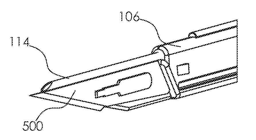
Body 106 further comprises a cylindrical tube 114 attached to a top surface of body 106. Preferably, cylindrical tube 114 is formed integral to body 106 and extends substantially the entire length of body 106. This allows a guidewire to extend behind the operator of surgical instrument 100 so it minimizes interference with a user. The proximal end of cylindrical tube 114 is preferably beveled (FIG. 5). The advantage of the bevel is that it results in a sharp tipped channel for cylindrical tube 114, allowing the channel to pass through the skin and soft tissue as the clinician makes a dermototomy incision.
The diameter of cylindrical tube 114 is great enough such that a guidewire may easily be passed therethrough. Only the first several millimeters of the cylindrical tube 114 channel need to be precisely fit the guidewire diameter to ensure that blade 500 is located close to the guidewire. The remaining portion of cylindrical tube 114 may have a wider diameter to minimize friction with the guidewire during advancement of surgical instrument 100.
Cover 108 is sized such that it surrounds body 106 as shown in FIG. 1-3. Cover 108 comprises channel 402 which is formed so to easily accommodate and slide over raised stop 112 and cylindrical tube 114. Sidewalls 404 extend downward from channel 402. Each sidewall 404 has a detent (not shown) that interlocks with grooves 110. In order to move cover 108 from a closed position (FIG. 3) to an open position (FIG. 5), a user presses button 406 (see FIG. 4). This causes tangs 408 to open outward, away from body 106. This forms a channel 410 which allows cover 108 to advance without being hindered by raised stop 112.
Once tangs 408 advance past the end of raised stop 112, tangs 108 return to their initial closed configuration. Now, the surgical device 100 is in an open position as shown in FIG. 5 and cover 108 is locked in this new open position. The length of channels 110 determines how securely that cover 108 is locked in both the open and closed positions of surgical device 100. Preferably, grooves 110 and raised stop 112 are the same length and begin/end at the same location on body 106.
When surgical device 100 is in an open position, blade 500 is exposed. Blade 500 is depicted in FIGS. 5-7. As shown, blade 500 comprises cutting edge 502, opening 504, and raised edge 506. Opening 504 is sized such that it locks onto a corresponding button 508 on body 106. This allows blade 500 to be securely attached to body 106. Raised edge 506 allows the tip of cutting edge 502 to extend close to the end of cylindrical tube 112, thus facilitating the centering of the guidewire with blade 500. Further, raised edge 506 allows a guidewire passed through cylindrical tube 114 to rest flush against the non-cutting edge of blade 500, eliminating any gaps between the guidewire wire and blade 500. Blade 500 may be made from any suitable material that is able to retain a sharp, surgical edge such as stainless steel, ceramic, etc.
Referring again to FIGS. 4, cover 108 additionally comprises cutout portion 412 which provides a user access to cylindrical tube 114 to thread the guidewire even when the surgical instrument 100 is in a closed position to minimize the risk of operator injury. The portion of cover 108 which extends in the proximal direction past cylindrical tube 114 serves to protect a user from blade 500 while still allowing easy access to cylindrical tube 114.
To use surgical instrument 100, a guidewire 802 is first threaded through cylindrical tube 114 as shown in FIG. 8. Next, the surgical instrument is opened as described with reference to FIGS. 3-5 to expose blade 500. The surgical instrument 100 can then be advanced over guidewire 802 to a skin surface in order to make an incision. Because surgical instrument 100 is relatively thin and has no side protrusions extending from it, surgical instrument 100 can easily be advanced through an incision without causing much trauma to adjacent tissue.
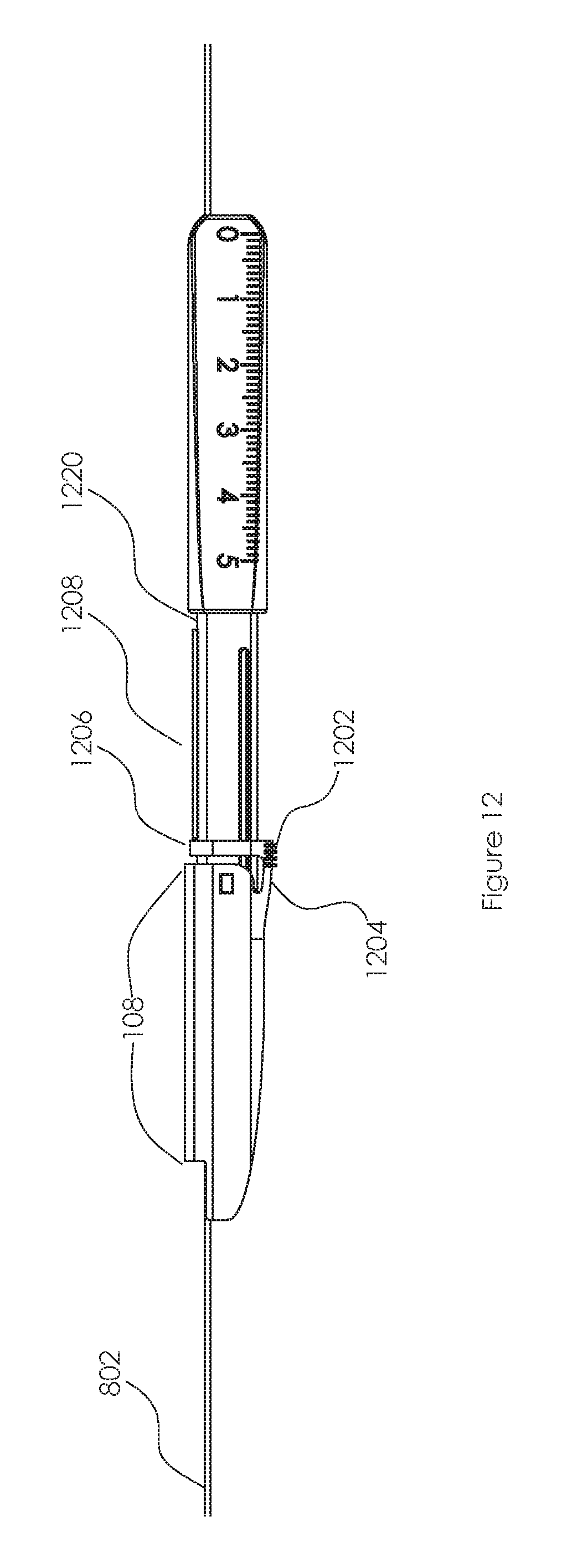
FIG. 12 depicts an alternate embodiment of surgical device 100 having a different mechanism for opening and closing cover 108. In this embodiment, cover 108 comprises button 1202, flexible member 1204, ledge 1206, and hump 1208. Preferably, ledge 1206 is u-shaped and extends around both sides of surgical device 100 and is connected to button 1202. Hump 1208 is preferably a semi-circular ridge extending along a top edge of surgical device 100. Flexible member 1204 is preferably constructed from a flexible, resilient material (e.g., a plastic) which can survive multiple bends.
Pressing button 1202 causes flexible member 1204 to flex toward cover 108, which in turn raises ledge 1206 over hump 1208. Cover 108 can then be slid to position 1210 (at an end of hump 1208). Here, flexible member 1204 returns to its initial unflexed position, thereby preventing further movement of cover 108.
FIGS. 13-15 depict another alternate embodiment of surgical device 100 in which the proximal end 104 can be separated from distal end 104. In this embodiment, distal end 104 comprises detent member 1402 which extends from protrusion 1404. Preferable, detent member 1402 has a width greater than that of protrusion 1404 and is made of stainless steel or hard plastic. Distal end 102 comprises cutout portion 1406 which is sized to accommodate detent member 1402. When proximal end 104 is attached to distal end 104, detent member 1402 locks into cutout portion 1406, thus firmly locking both ends together. By using this configuration, distal end 104 can be used repeatedly while proximal end 102 can be disposed after use. It should be obvious that the shape of detent member 1402 can be modified to fit onto any variety of existing detachable scalpel handles.
Device Manufacture
Due to the manufacturing difficulties in molding a long narrow slot like cylindrical tube 114, it is preferable to manufacture body 106 in two halves which can later be joined using sonic welding, adhesive, or any other known methods to secure the two halves. Examples of the two halves that may be joined to form body 106 are depicted in FIGS. 9-11.
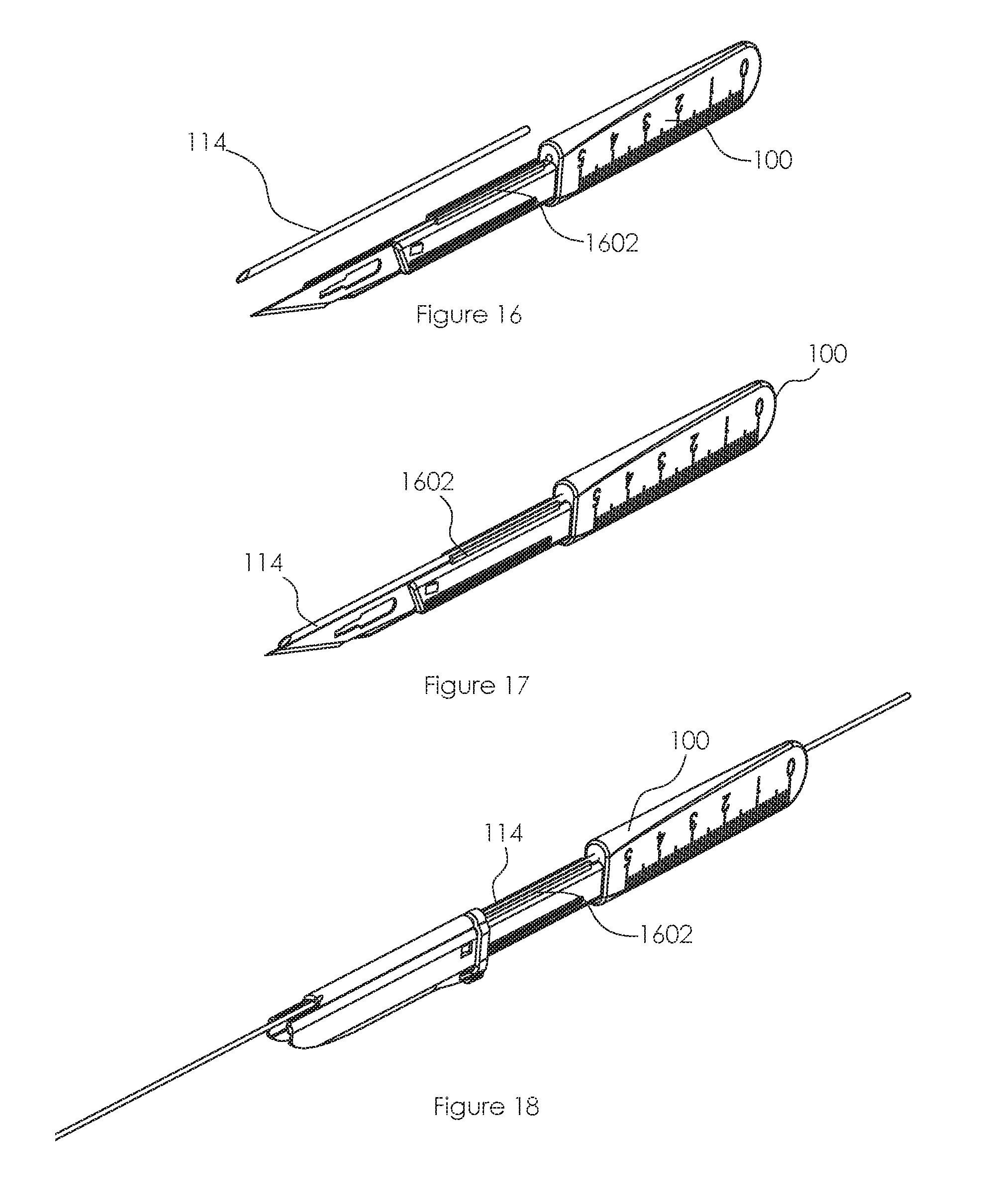
Another possible method of overcoming these manufacturing difficulties is to manufacture the handle without the channel but with provisions to accommodate a separately manufactured tube to be added. For example, as depicted in FIGS. 16-18, surgical device 100 can be manufacture without cylindrical tube 114 (FIG. 16). Cylindrical tube 114 can be manufactured in a separate process and added to surgical device 100 by inserting cylindrical tube 114 into retaining channel 1602 (FIGS. 17 and 18). Other connection techniques, such as a snap fit connection, can also be utilized.
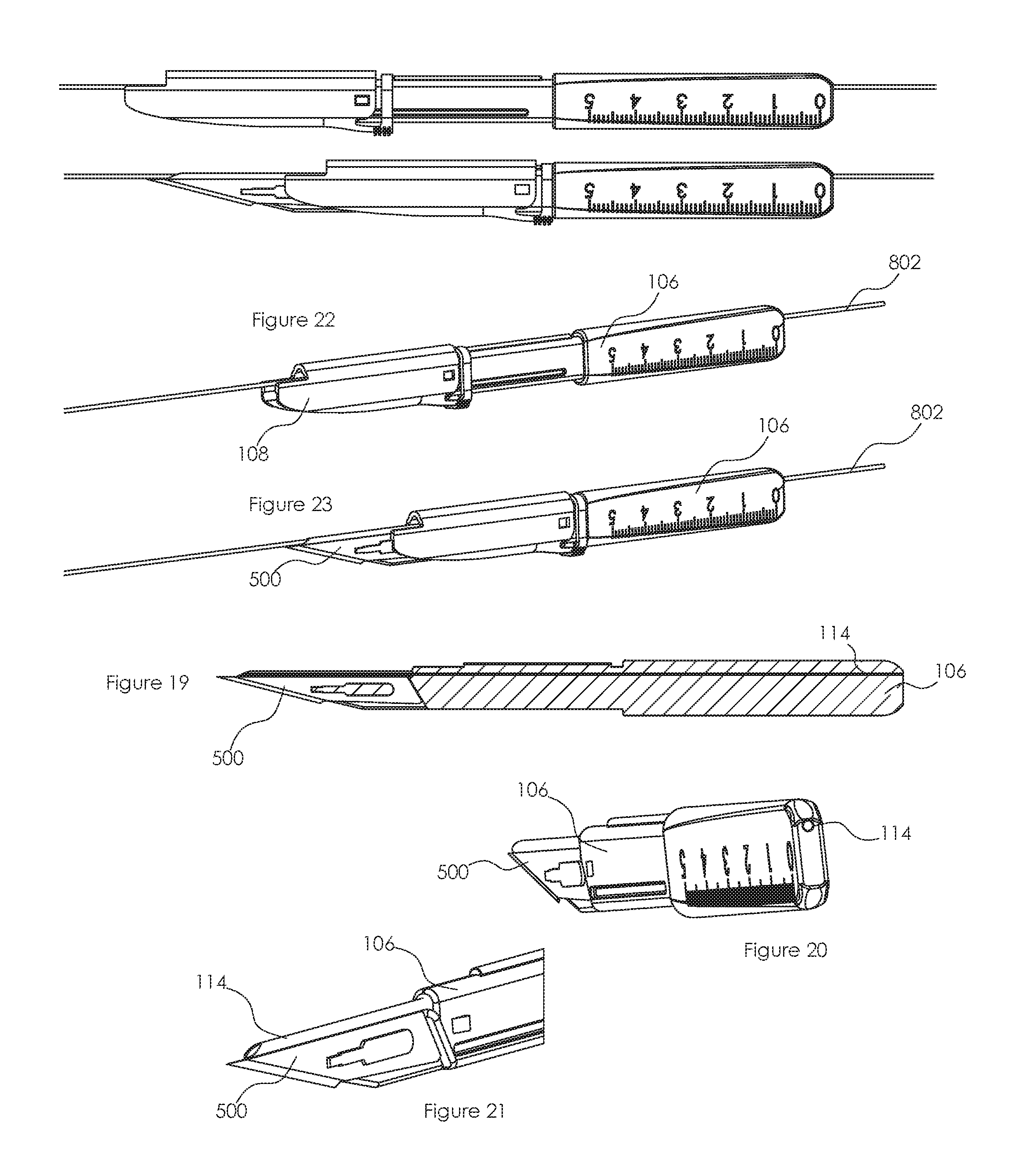
In some embodiments, it may be desirable to permanently connect cylindrical tube 114 to surgical device 100. For example, as shown in FIG. 19, cylindrical tube 114 may run the entire length of surgical device 100. To accomplish this configuration, cylindrical tube 114, which is preferably stainless steel in this embodiment, is placed in a mold for body 106. Cylindrical tube 114 is then over molded so that it is encased in body 106 (i.e., cylindrical tube 114 is inserted into the mold and then plastic is injected around it). As shown in FIG. 20, the cylindrical tube 114 extends to the back of body 106. Further, as shown in FIG. 21, the front of cylindrical tube 114 protrudes over blade 500. A guidewire 802 can be inserted through cylindrical tube 114 as shown in FIGS. 22 and 23 and surgical device 100 can be used as previously described.
This embodiment of surgical device 100 is similar to that depicted in FIGS. 1-8. However, in this embodiment, cylindrical tube 114 is a metal tube that has been integrated into body 106 instead of a molded channel. However, the change in manufacturing does not affect the use of surgical device 100.
* * * * *
D00000
D00001
D00002
D00003
D00004
D00005
D00006
D00007
XML
uspto.report is an independent third-party trademark research tool that is not affiliated, endorsed, or sponsored by the United States Patent and Trademark Office (USPTO) or any other governmental organization. The information provided by uspto.report is based on publicly available data at the time of writing and is intended for informational purposes only.
While we strive to provide accurate and up-to-date information, we do not guarantee the accuracy, completeness, reliability, or suitability of the information displayed on this site. The use of this site is at your own risk. Any reliance you place on such information is therefore strictly at your own risk.
All official trademark data, including owner information, should be verified by visiting the official USPTO website at www.uspto.gov. This site is not intended to replace professional legal advice and should not be used as a substitute for consulting with a legal professional who is knowledgeable about trademark law.