Ferroresonant transformer systems and methods with selectable input and output voltages for use in uninterruptible power supplies
Le , et al. A
U.S. patent number 10,381,867 [Application Number 15/294,571] was granted by the patent office on 2019-08-13 for ferroresonant transformer systems and methods with selectable input and output voltages for use in uninterruptible power supplies. This patent grant is currently assigned to ALPHA TECHNOLOGEIS SERVICES, INC.. The grantee listed for this patent is Alpha Technologies Inc.. Invention is credited to Pankaj H. Bhatt, Thanh Quoc Le, Thomas Patrick Newberry.


| United States Patent | 10,381,867 |
| Le , et al. | August 13, 2019 |
Ferroresonant transformer systems and methods with selectable input and output voltages for use in uninterruptible power supplies
Abstract
A ferroresonant transformer system has a core, a shunt, first and second input windings, an inverter winding, a tank winding, a resonant capacitor, an output capacitor, and a plurality of switches. The tank winding defines a plurality of switch tap locations and at least two output tap locations. The resonant capacitor is connected across at least a portion of the tank winding. Each switch is operatively connectable between one of the switch tap locations and the resonant capacitor. Each output terminal is operatively connected to one of the at least two output tap locations.
| Inventors: | Le; Thanh Quoc (Ferndale, WA), Bhatt; Pankaj H. (Bellingham, WA), Newberry; Thomas Patrick (Blaine, WA) | ||||||||||
|---|---|---|---|---|---|---|---|---|---|---|---|
| Applicant: |
|
||||||||||
| Assignee: | ALPHA TECHNOLOGEIS SERVICES,
INC. (Bellingham, WA) |
||||||||||
| Family ID: | 67543674 | ||||||||||
| Appl. No.: | 15/294,571 | ||||||||||
| Filed: | October 14, 2016 |
Related U.S. Patent Documents
| Application Number | Filing Date | Patent Number | Issue Date | ||
|---|---|---|---|---|---|
| 62242862 | Oct 16, 2015 | ||||
| Current U.S. Class: | 1/1 |
| Current CPC Class: | H02J 9/06 (20130101); H02J 9/061 (20130101); H02M 7/44 (20130101); H02M 1/10 (20130101); H02J 9/00 (20130101); H02M 5/12 (20130101); H02J 9/067 (20200101) |
| Current International Class: | H02J 9/00 (20060101); H02J 9/06 (20060101); H02M 7/44 (20060101) |
| Field of Search: | ;307/23 |
References Cited [Referenced By]
U.S. Patent Documents
| 352105 | November 1886 | Zipernowsky et al. |
| 375614 | December 1887 | Eickemeyer |
| 414266 | November 1889 | Thomson |
| 1718238 | June 1929 | Kettering et al. |
| 1950396 | March 1934 | Boucher |
| 2007415 | July 1935 | Walker |
| 2014101 | September 1935 | Bryan |
| 2037183 | April 1936 | Strieby |
| 2037188 | April 1936 | Russell |
| 2036994 | December 1936 | Frank et al. |
| 2063994 | December 1936 | Frank et al. |
| 2085072 | June 1937 | Bobe |
| 2165969 | July 1939 | Humbert et al. |
| 2240123 | April 1941 | Shoup et al. |
| 2302192 | November 1942 | Dannheiser |
| 2352073 | June 1944 | Boucher et al. |
| 2427678 | September 1947 | Laging |
| 2444794 | July 1948 | Uttal et al. |
| 2512976 | June 1950 | Smeltzly |
| 2688704 | September 1954 | Christenson |
| 2856543 | October 1958 | Dixon et al. |
| 2920211 | January 1960 | Gotoh |
| 2996656 | August 1961 | Sola |
| 3022458 | February 1962 | Sola |
| 3064195 | November 1962 | Freen |
| 3221172 | November 1965 | Rolison |
| 3283165 | November 1966 | Bloch |
| 3293445 | December 1966 | Levy |
| 3304599 | February 1967 | Nordin |
| 3305762 | February 1967 | Geib, Jr. |
| 3339080 | August 1967 | Howald |
| 3345517 | October 1967 | Smith |
| 3348060 | October 1967 | Jamieson |
| 3389329 | June 1968 | Quirk et al. |
| 3435358 | March 1969 | Rheinfelder |
| 3458710 | July 1969 | Dodge |
| 3521152 | July 1970 | Emerson |
| 3525035 | August 1970 | Kakalec |
| 3525078 | August 1970 | Baggott |
| 3546571 | December 1970 | Fletcher et al. |
| 3590362 | June 1971 | Kakalec |
| 3636368 | January 1972 | Sia |
| 3678284 | July 1972 | Peters |
| 3678377 | July 1972 | Chiffert |
| 3686561 | August 1972 | Spreadbury |
| 3691393 | September 1972 | Papachristou |
| 3737858 | June 1973 | Turner et al. |
| 3742251 | June 1973 | Thompson et al. |
| 3823358 | July 1974 | Rey |
| 2860748 | January 1975 | Everhart et al. |
| 3859589 | January 1975 | Rush |
| 3860748 | January 1975 | Everhart et al. |
| 3873846 | March 1975 | Morio et al. |
| 3909560 | September 1975 | Martin et al. |
| 3916295 | October 1975 | Hunter |
| 3938033 | February 1976 | Borkovitz et al. |
| 3943447 | March 1976 | Shomo, III |
| 4004110 | January 1977 | Whyte |
| 4010381 | March 1977 | Fickenscher et al. |
| 4060844 | November 1977 | Davis et al. |
| 4122382 | October 1978 | Bernstein |
| 4130790 | December 1978 | Heisey |
| 4170761 | October 1979 | Koppehele |
| 4198624 | April 1980 | Watanabe |
| 4217533 | August 1980 | Van Beek |
| 4251736 | February 1981 | Coleman |
| 4262245 | April 1981 | Wendt |
| 4270080 | May 1981 | Kostecki |
| 4277692 | July 1981 | Small |
| 4295053 | October 1981 | Kovatch et al. |
| 4295054 | October 1981 | Kovatch et al. |
| 4313060 | January 1982 | Fickenscher et al. |
| 4353014 | October 1982 | Willis |
| 4366389 | December 1982 | Hussey |
| 4366390 | December 1982 | Rathmann |
| 4385263 | May 1983 | Luz |
| 4400624 | August 1983 | Ebert, Jr. |
| 4400625 | August 1983 | Hussey |
| 4423379 | December 1983 | Jacobs et al. |
| 4446458 | May 1984 | Cook |
| 4460834 | July 1984 | Gottfried |
| 4466041 | August 1984 | Witulski et al. |
| 4472641 | September 1984 | Dickey et al. |
| 4475047 | October 1984 | Ebert |
| 4477799 | October 1984 | Rocci et al. |
| 4510401 | April 1985 | Legoult |
| 4604530 | August 1986 | Shibuya |
| 4616305 | October 1986 | Damiano et al. |
| 4628426 | December 1986 | Steigerwald |
| 4631471 | December 1986 | Fouad et al. |
| 4656412 | April 1987 | McLyman |
| 4670702 | June 1987 | Yamada et al. |
| 4673825 | June 1987 | Raddi et al. |
| 4686375 | August 1987 | Gottfried |
| 4697134 | September 1987 | Burkum et al. |
| 4700122 | October 1987 | Cimino et al. |
| 4709318 | November 1987 | Gephart et al. |
| 4719427 | January 1988 | Morishita et al. |
| 4719550 | January 1988 | Powell et al. |
| 4775800 | January 1988 | Wood |
| 4724290 | February 1988 | Campbell |
| 4724478 | February 1988 | Masuko et al. |
| 4730242 | March 1988 | Divan |
| 4733223 | March 1988 | Gilbert |
| 4740739 | April 1988 | Quammen et al. |
| 4745299 | May 1988 | Eng et al. |
| 4748341 | May 1988 | Gupta |
| 4748342 | May 1988 | Dijkmans |
| 4763014 | August 1988 | Model et al. |
| 4791542 | December 1988 | Piaskowski |
| 4829225 | May 1989 | Podrazhansky et al. |
| 4860185 | August 1989 | Brewer et al. |
| 4864483 | September 1989 | Divan |
| 4882717 | November 1989 | Hayakawa et al. |
| 4885474 | December 1989 | Johnstone et al. |
| 4890213 | December 1989 | Seki |
| 4916329 | April 1990 | Dang et al. |
| 4920475 | April 1990 | Rippel |
| 4922125 | May 1990 | Casanova et al. |
| 4926084 | May 1990 | Furutsu et al. |
| 4943763 | July 1990 | Bobry |
| 4952834 | August 1990 | Okada |
| 4954741 | September 1990 | Furutsu et al. |
| 4975649 | December 1990 | Bobry |
| 4988283 | January 1991 | Nagasawa et al. |
| 5010469 | April 1991 | Bobry |
| 5017800 | May 1991 | Divan |
| 5027264 | June 1991 | DeDoncker et al. |
| 5029285 | July 1991 | Bobry |
| 5057698 | October 1991 | Widener et al. |
| 5099410 | March 1992 | Divan |
| 5137020 | August 1992 | Wayne et al. |
| 5148043 | September 1992 | Hirata et al. |
| 5154986 | October 1992 | Takechi et al. |
| 5168205 | December 1992 | Kan et al. |
| 5172009 | December 1992 | Mohan |
| 5185536 | February 1993 | Johnson, Jr. et al. |
| 5193067 | March 1993 | Sato et al. |
| 5198698 | March 1993 | Paul et al. |
| 5198970 | March 1993 | Kawabata et al. |
| 5200586 | April 1993 | Smith et al. |
| 5200643 | April 1993 | Brown |
| 5220597 | June 1993 | Horiuchi |
| 5224025 | June 1993 | Divan et al. |
| 5229650 | July 1993 | Kita et al. |
| 5237208 | August 1993 | Tominaga et al. |
| 5241591 | August 1993 | Saji |
| 5281919 | January 1994 | Palanisamy |
| 5302858 | April 1994 | Folts |
| 5334057 | August 1994 | Blackwell |
| 5400005 | March 1995 | Bobry |
| 5402053 | March 1995 | Divan et al. |
| 5410720 | April 1995 | Osterman |
| 5440179 | August 1995 | Severinsky |
| 5457377 | October 1995 | Jonsson |
| 5467384 | November 1995 | Skinner, Sr. |
| 5483463 | January 1996 | Qin et al. |
| 5532525 | July 1996 | Kaiser et al. |
| 5579197 | November 1996 | Mengelt et al. |
| 5581246 | December 1996 | Yarberry et al. |
| 5602462 | February 1997 | Stich et al. |
| 5610451 | March 1997 | Symonds |
| 5635773 | June 1997 | Stuart |
| 5638244 | June 1997 | Mekanik et al. |
| 5642002 | June 1997 | Mekanik et al. |
| 5664002 | September 1997 | Skinner, Sr. |
| 5734831 | March 1998 | Sanders |
| 5739595 | April 1998 | Mekanik et al. |
| 5745356 | April 1998 | Tassitino, Jr. et al. |
| 5747887 | May 1998 | Takanaga et al. |
| 5747888 | May 1998 | Zilberberg |
| 5760495 | June 1998 | Mekanik |
| 5768117 | June 1998 | Takahashi et al. |
| 5783932 | July 1998 | Namba et al. |
| 5790391 | August 1998 | Stich et al. |
| 5804890 | September 1998 | Kakalec et al. |
| 5844327 | December 1998 | Batson |
| 5845190 | December 1998 | Bushue et al. |
| 5880536 | March 1999 | Mardirossian |
| 5892431 | April 1999 | Osterman |
| 5897766 | April 1999 | Kawatsu |
| 5901057 | May 1999 | Brand et al. |
| 5925476 | July 1999 | Kawatsu |
| 5961604 | October 1999 | Anderson et al. |
| 5982412 | November 1999 | Nulty |
| 5982645 | November 1999 | Levran et al. |
| 5982652 | November 1999 | Simonelli et al. |
| 5994793 | November 1999 | Bobry |
| 5994794 | November 1999 | Wehrlen |
| 6011324 | January 2000 | Kohlstruck et al. |
| 6014015 | January 2000 | Thorne et al. |
| 6028414 | February 2000 | Chouinard et al. |
| 6069412 | May 2000 | Raddi et al. |
| 6074246 | June 2000 | Seefeldt et al. |
| 6100665 | August 2000 | Alderman |
| 6198178 | March 2001 | Schienbein et al. |
| 6212081 | April 2001 | Sakai |
| 6218744 | April 2001 | Zahrte et al. |
| 6288456 | September 2001 | Crafty |
| 6288916 | September 2001 | Liu et al. |
| 6295215 | September 2001 | Faria et al. |
| 6344985 | February 2002 | Akerson |
| 6348782 | February 2002 | Oughton et al. |
| 6426610 | July 2002 | Janik |
| 6433905 | August 2002 | Price et al. |
| 6456036 | September 2002 | Thandiwe |
| 6465910 | October 2002 | Young et al. |
| 6486399 | November 2002 | Armstrong et al. |
| 6602627 | August 2003 | Liu et al. |
| 6738435 | May 2004 | Becker |
| 6768722 | July 2004 | Katseff et al. |
| 6841971 | January 2005 | Spee et al. |
| 6906933 | June 2005 | Taimela |
| 6933626 | August 2005 | Oughton |
| 7040920 | May 2006 | Johnson et al. |
| 7043049 | May 2006 | Kuzma |
| 7102251 | September 2006 | West |
| 7182632 | February 2007 | Johnson et al. |
| 7449798 | November 2008 | Suzuki et al. |
| 7543328 | June 2009 | Bialk et al. |
| 7567520 | July 2009 | Ostrosky |
| 7835379 | November 2010 | Dravida et al. |
| 8074888 | December 2011 | Naccache |
| 8344685 | January 2013 | Bertness et al. |
| 8575779 | November 2013 | Le et al. |
| 8616457 | December 2013 | Krawczewicz et al. |
| 9030045 | May 2015 | Richardson et al. |
| 9030048 | May 2015 | Heidenreich et al. |
| 9234916 | January 2016 | Peck et al. |
| 9312726 | April 2016 | Heidenreich et al. |
| 9633781 | April 2017 | Le |
| 9812900 | November 2017 | Richardson et al. |
| 9881625 | January 2018 | Liu et al. |
| 2001/0033502 | October 2001 | Blair et al. |
| 2003/0046706 | March 2003 | Rakib |
| 2003/0048006 | March 2003 | Shelter et al. |
| 2004/0031059 | February 2004 | Bialk et al. |
| 2004/0207366 | October 2004 | Sung |
| 2005/0096772 | May 2005 | Cox et al. |
| 2005/0258927 | November 2005 | Lu |
| 2006/0168612 | July 2006 | Chapman et al. |
| 2007/0002875 | January 2007 | Rocci et al. |
| 2007/0262650 | November 2007 | Li |
| 2008/0024268 | January 2008 | Wong et al. |
| 2008/0203820 | August 2008 | Kramer et al. |
| 2008/0278006 | November 2008 | Gottlieb et al. |
| 2009/0076661 | March 2009 | Pearson et al. |
| 2009/0196082 | August 2009 | Mazumder et al. |
| 2009/0240377 | September 2009 | Batzler et al. |
| 2010/0008397 | January 2010 | Johnson |
| 2010/0045107 | February 2010 | Cohen et al. |
| 2010/0161259 | June 2010 | Kim et al. |
| 2010/0191387 | July 2010 | Warren et al. |
| 2010/0250192 | September 2010 | Deokar et al. |
| 2010/0324548 | December 2010 | Godara et al. |
| 2010/0328851 | December 2010 | Jurek |
| 2011/0187197 | August 2011 | Moth |
| 2011/0238345 | September 2011 | Gauthier et al. |
| 2011/0273151 | November 2011 | Lesso et al. |
| 2012/0051734 | March 2012 | Weiss et al. |
| 2012/0091811 | April 2012 | Heidenreich et al. |
| 2012/0127800 | August 2012 | Heidenreich et al. |
| 2012/0212051 | August 2012 | Heidenreich et al. |
| 2012/0217800 | August 2012 | Heidenreich et al. |
| 2012/0217806 | August 2012 | Heidenreich et al. |
| 2012/0217808 | August 2012 | Richardson et al. |
| 2013/0113287 | May 2013 | Singh et al. |
| 2013/0162650 | June 2013 | Marivoet et al. |
| 2013/0312020 | November 2013 | Talbert |
| 2014/0062189 | March 2014 | Le et al. |
| 2014/0254392 | September 2014 | Wolcott et al. |
| 2015/0241892 | August 2015 | Gaucher et al. |
| 2015/0244211 | August 2015 | Richardson et al. |
| 2017/0229906 | August 2017 | Le et al. |
| 2018/0062427 | March 2018 | Richardson et al. |
| 2019/0018437 | January 2019 | Le |
| 687528 | Dec 1995 | AU | |||
| 2029495 | Dec 1995 | AU | |||
| 2015203667 | Mar 2017 | AU | |||
| 1265231 | Jan 1990 | CA | |||
| 2033685 | Oct 1991 | CA | |||
| 2036296 | Nov 1991 | CA | |||
| 1297546 | Mar 1992 | CA | |||
| 2086897 | Jul 1993 | CA | |||
| 2149845 | Dec 1995 | CA | |||
| 2168520 | Aug 1996 | CA | |||
| 2028269 | Jan 2000 | CA | |||
| 2403888 | Sep 2001 | CA | |||
| 2713017 | Jul 2009 | CA | |||
| 2504101 | May 2010 | CA | |||
| 2760581 | Nov 2010 | CA | |||
| 101330686 | Mar 2012 | CN | |||
| 2602789 | Jul 1977 | DE | |||
| 2809514 | Sep 1978 | DE | |||
| 3321649 | Dec 1983 | DE | |||
| 0196004 | Nov 1993 | EP | |||
| 0284541 | Sep 1998 | EP | |||
| 2425515 | Mar 2012 | EP | |||
| 2587620 | May 2013 | EP | |||
| 2858015 | Apr 2015 | EP | |||
| 762789 | Apr 1934 | FR | |||
| 861215 | Feb 1941 | FR | |||
| 188405201 | Mar 1884 | GB | |||
| 005201 | Apr 1885 | GB | |||
| 260731 | Sep 1925 | GB | |||
| 2005118 | Apr 1979 | GB | |||
| 2120474 | Nov 1983 | GB | |||
| 2137033 | Mar 1984 | GB | |||
| 2171861 | Sep 1986 | GB | |||
| 2185326 | Oct 1986 | GB | |||
| 2355350 | Apr 2001 | GB | |||
| 2475612 | May 2011 | GB | |||
| S5482053 | Jun 1979 | JP | |||
| S5532133 | Mar 1980 | JP | |||
| S5650417 | May 1981 | JP | |||
| S56155420 | Dec 1981 | JP | |||
| 2000350381 | Dec 2000 | JP | |||
| 2001190035 | Jul 2001 | JP | |||
| 2005295776 | Oct 2005 | JP | |||
| 2010136547 | Jun 2010 | JP | |||
| 2010252573 | Nov 2010 | JP | |||
| 20070108759 | Nov 2007 | KR | |||
| 2191459 | Oct 2002 | RU | |||
| 2221320 | Oct 2004 | RU | |||
| 2304335 | Aug 2007 | RU | |||
| 200941897 | Oct 2009 | TW | |||
| I539721 | Jun 2016 | TW | |||
| 8501842 | Apr 1985 | WO | |||
| 002118 | Apr 2000 | WO | |||
| 2009094540 | Jul 2009 | WO | |||
| 2010135406 | Nov 2010 | WO | |||
| 2011103131 | Dec 2011 | WO | |||
| 2012099911 | Jul 2012 | WO | |||
| 2012144127 | Oct 2012 | WO | |||
| 2012148512 | Nov 2012 | WO | |||
| 2012112252 | Jan 2013 | WO | |||
| 2013106356 | Jul 2013 | WO | |||
| 2017044970 | Mar 2017 | WO | |||
| 2019014682 | Jan 2019 | WO | |||
| 2019051321 | Mar 2019 | WO | |||
| 2019051499 | Mar 2019 | WO | |||
Other References
|
Smart Powershop/Smart Energy Systems International AG, "Off-Grid SMA Power Set XS," Sep. 29, 2010, 5 pages. cited by applicant . Spears, "Disturbances Can Toast Your System," Reprint from Communications Technology, Apr. 2000, 4 pages. cited by applicant . Stewart Nowak, Power Problems: Selecting a UPS, Electronics Test, Jul. 13, 1990, 4 pages, No. 7, San Francisco, CA, US. cited by applicant . USPTO, "Final Office Action, U.S. Appl. No. 14/516,522,", dated Jan. 8, 2019, 22 pages. cited by applicant . Wallace et al., Wireless Load Sharing of Single Phase Telecom Inverters, Telecommunication Energy Conference, 1999, 13 pages. cited by applicant . Xia, Ordinary Meter Measures Battery Resistance, EDN-Design Ideas, Jun. 24, 1993, 2 pages. cited by applicant . Yamada, Research and Development of Telecommunications Energy Systems in NTT, NTT Integrated Infromation and Energy Systems Laboratories, Mar. 9, 2011, 8 pages. cited by applicant . Alpha Technologies, Inc., Cheetah CMD-N GS7000 Transponder, 2015, offer for sale 2009, 2 pages. cited by applicant . Alpha Technologies, Inc., Cheetah CMD-N Harmonic Transponder, 2015, offer for sale 2007, 2 pages. cited by applicant . Alpha Technologies, Inc., Cheetah XD Network Tracker Plus, 2015, offer for sale Nov. 2011, 2 pages. cited by applicant . Alpha Technologies, Inc., Power Technical Bulletin DSM3 vs DSM1 Provisioning, Dec. 2010, 4 pages. cited by applicant . Batson et al., Solving the Powering Requirements of Broadband Dial Tone Service, 1994, 3 pages. cited by applicant . Bridge et al., "Preventing outages without batteries," CED, Jun. 1999, 7 pages. cited by applicant . Broadband Business and News Perspective, "Cable operators feeling power surge," Reprinted from CED, Apr. 2000, 4 pages. cited by applicant . Cheetah Technologies, L.P., Cheetah CMD-N. Arris SG4000, 2014, offer for sale Feb. 3, 2011, 2 pages. cited by applicant . Cheetah Technologies, L.P., Cheetah CMD-P+ DOCSIS-based Transponder for Cable Power Systems, 2014, offer for sale 2008, 3 pages. cited by applicant . Cheetah Technologies, L.P., CMD-P+ Transponder User Manual, Mar. 18, 2011, 88 pages. cited by applicant . Contino et al., Water-Cooling Applications for Telecommunications and Computer Energy Systems, Telecommunications Energy Conference, IEEE, 1988, pp. 441-447. cited by applicant . Electroline Equipment Inc., DOCSIS 2.0 and EuroDOCSIS Status Monitoring Transponder for Power Supplies, 2006, 2 pages. cited by applicant . Eto et al., Research, Development, and Demonstration Needs for Large-Scale, Reliability-Enhancing, Integration of Distributed Energy Resources, IEEE Proceedings of the 33rd Hawaii International Conference on System Sciences, 2000, 7 pages. cited by applicant . European Patent Office, "Extended European Search Report", Application No. 16845289.4, Dec. 19, 2018, 10 pages. cited by applicant . H.C. Gerdes et al., A Practical Approach to Understanding Ferroresonance, EEE-Circuit Design Engineering, pp. 37-89, Apr. 1966. cited by applicant . Hart et al., The Derivation and Application of Design Equations for Ferroresonant Voltage Regulators and Regulated Rectifiers, IEEE Transactions on Magnetics, vol. MAG-7, No. 1, Mar. 1971, pp. 205-211. cited by applicant . Hitron Technologies Inc., DNP-30341 DOCSIS-Based Downstream Monitor, Sep. 2012, 2 pages. cited by applicant . IEEE Standard for Ferroresonant Voltage Regulators, Electronics Transformer Technical Committee of the IEEE Power Electronics Society, IEEE Std. 449-1990, May 16, 1990, 29 pages. cited by applicant . IMEON Energy, "IMEON 3.6 User Guide", no date, 20 pages. cited by applicant . IMEON Energy, "Self Consumption Smart Grid Inverter", 2016, 3 pages. cited by applicant . IMEON Energy, "Self Consumption Smart Grid Inverter", no date, 2 pages. cited by applicant . IMEON Energy, "The Self Consumption Smart Grid Inverter New Generation", no date, 8 pages. cited by applicant . International Search Report, PCT/US99/19677, dated Feb. 8, 2000, 5 pages. cited by applicant . International Searching Authority, "PCT/US2011/025000", International Search Report, dated Oct. 26, 2011, 9 pages. cited by applicant . International Searching Authority, "PCT/US2012/021619", International Search Report, dated May 17, 2012, 7 pages. cited by applicant . International Searching Authority, ISR & Written Opinion, PCT/US2018/050094, dated Dec. 27, 2018, 7 pages. cited by applicant . International Searching Authority, ISR & Written Opinion, PCT/US2018/050500, dated Feb. 28, 2019, 6 pages. cited by applicant . International Searching Authority, ISR, PCT/US2012/021622, dated May 17, 2012, 7 pages. cited by applicant . International Searching Authority, PCT Notification of Transmittal of the International Search Report and the Written Opinion of the International Searching Authority, or the Declaration, dated Dec. 8, 2016, 8 pages. cited by applicant . Ivensys, "Power When You Really Need It!" Publication No. CSG29FXA, Feb. 2000, 2 pages. cited by applicant . Ivensys, "Sometimes Less Is More!" Publication No. CSG28FXA, Feb. 2000, 2 pages. cited by applicant . Jain et al., High Frequency Triport UPS Topologies for Emerging Fiber Networks, Telecommunications Energy conference, IEEE, 1998, pp. 505-512. cited by applicant . Jefferson T. Mitchell et al., Rectifiers and Energy Conservation, Telecommunications, Mar. 1979, 3 pages. cited by applicant . Kakalec, "A Feedback-Controlled Ferroresonant Voltage Regulator," IEEE Transactions of Magnetics, Mar. 1970, 5 pages, vol. Mag-6, No. 1. cited by applicant . Lectro Products Incorporated, "Lectro Ferro Family," Publication No. CSG16FXA, Nov. 1998, 4 pages. cited by applicant . Lectro Products Incorporated, "Solving CATV Power Solutions," Publication No. CSG24FYA, Jun. 1999, 12 pages. cited by applicant . Marcotte et al, "Powering Cable TV Systems," Reprinted from Broadband Systems & Design, Jun. 1996, 4 pages. cited by applicant . Marcotte, "Power migration strategies for future-proofing," Reprinted from CED Magazine, Jun. 1997, 4 pages. cited by applicant . McGraw-Hill, Dictionary of Scientific and Technical Terms Fifth Edition, p. 745 and pp. 1696-1697, 1994. cited by applicant . Multipower, Inc., "Confluence Newsletters, vols. I and II," "MP 900," "MP1350," web site http://www.multipowerups.com/index.htm, Aug. 2000, 16 pages. cited by applicant . Nedap, "Data sheet fro 24 Vdc lead-acid batteries, PowerRouter Solar Battery the innovative all-in-one-unit", no date, 2 pages. cited by applicant . Nedap, "Installation Manual PowerRouter Solar Inverter", Jan. 9, 2013, 46 pages. cited by applicant . Nedap, "Installer Manual PowerRouter Solar Inverter", Jan. 9, 2013, 46 pages. cited by applicant . Nedap, "PowerRouter Connect, Technical data", no date, 1 page. cited by applicant . Nedap, "PowerRouter Solar, Technical data", no date, 1 page. cited by applicant . Phoenix Broadband Technologies, L.L.C., Installation & Operation Manual, 2005, 44 pages. cited by applicant . Rando, AC Triport--A New Uninterruptible AC Power Supply, Telephone Energy Conference, IEEE, 1978, pp. 50-58. cited by applicant . Rex Teets, Application and Design of Ferroresonant Transformers, No Date, pp. 28-34. cited by applicant . Robert J. Kakalec et al., New Technology for Battery-Charging Rectifiers, Bell Laboratories Record, May 1979, pp. 131-134. cited by applicant. |
Primary Examiner: Barnie; Rexford N
Assistant Examiner: Inge; Joseph N
Attorney, Agent or Firm: Schacht; Michael R. Schacht Law Office, Inc.
Parent Case Text
RELATED APPLICATIONS
This application, U.S. patent application Ser. No. 15/294,571, filed Oct. 14, 2016--claims priority of U.S. Provisional Application Ser. No. 62/242,862, filed on Oct. 16, 2015. The contents of the application listed above is incorporated herein by reference.
Claims
What is claimed is:
1. A power supply adapted to be connected to a source of utility power and a load, comprising: a ferroresonant transformer system comprising a core; a shunt; first and second input windings; an inverter winding; a tank winding defining a plurality of switch tap locations and at least two output tap locations; a resonant capacitor connected across at least a portion of the tank winding; an output capacitor operatively connected to ground; a plurality of switches, where each switch is operatively connected between one of the switch tap locations and the resonant capacitor; and a plurality of output terminals, where each output terminal is operatively connected to one of the at least two output tap locations; a battery system; and an inverter operatively coupled between the battery system and the inverter winding; whereby at least one of the first and second input windings is connected to the source of utility power; at least two output terminals are operatively connected to the load; and to regulate an output voltage of the ferroresonant transformer system, a selected switch of the plurality of switches is closed while any non-selected switch of the plurality of switches is open such that the output capacitor is operatively connected to a desired switch tap location of the plurality of switch tap locations.
2. A power supply as recited in claim 1, in which the first and second input windings are connected in series.
3. A power supply as recited in claim 1, in which the first and second input windings are connected in parallel.
4. A power supply as recited in claim 1, further comprising a controller for controlling the plurality of switches based on at least one of an output voltage, an output current, and an input voltage.
5. A power supply as recited in claim 1, further comprising a controller for controlling the plurality of switches based on an output voltage, an output current, and an input voltage.
6. A method of providing power from a source of utility power to a load, comprising the steps of: providing a ferroresonant transformer comprising a core; a shunt; a first and second input windings; an inverter winding; a tank winding defining a plurality of switch tap locations and at least two output tap locations; operatively connecting a resonant capacitor across at least a portion of the tank winding; operatively connecting an output capacitor to ground; operatively connecting each of a plurality of switches between one of the switch tap locations and the resonant capacitor; operatively connecting each of a plurality of output terminals to one of the at least two output tap locations; operatively connecting a battery system to an inverter; operatively connecting the inverter to the inverter winding; operatively connecting at least one of the first and second input windings to the source of utility power; operatively connecting at least two output terminals to the load; and selecting one of the plurality of switches as a selected switch; controlling the plurality of switches to provide a desired output power signal to the load by closing only the selected switch of the plurality of switches such that the output capacitor is operatively connected to a desired switch tap location of the plurality of switch tap locations.
7. A method as recited in claim 6, further comprising the step of connecting the first and second input windings in series.
8. A method as recited in claim 6, further comprising the step of connecting the first and second input windings in parallel.
9. A method as recited in claim 6, further comprising the step of controlling the plurality of switches based on at least one of an output voltage, an output current, and an input voltage.
10. A method as recited in claim 6, further comprising the step of controlling the plurality of switches based on an output voltage, an output current, and an input voltage.
Description
TECHNICAL FIELD
The present invention relates to ferroresonant transformers systems and, in particular, ferroresonant transformers systems for use in uninterruptible power supplies that are capable of accommodating different input and output voltages.
BACKGROUND
Uninterruptible power supplies are ideally capable of operating in operating environments having differing utility voltage standards. The need exists for improved uninterruptible power supplies, and ferroresonant transformer systems for use in such improved uninterruptible power supplies, capable of being easily and quickly field-modified to operate using different utility voltage standards.
SUMMARY
The present invention may be embodied as a ferroresonant transformer system comprising a core, a shunt, first and second input windings, an inverter winding, a tank winding, a resonant capacitor, an output capacitor, a plurality of switches, and at least two output terminals. The tank winding defines a plurality of switch tap locations and at least two output tap locations. The resonant capacitor is connected across at least a portion of the tank winding. Each switch is operatively connectable between one of the switch tap locations and the resonant capacitor. Each output terminal is operatively connected to one of the at least two output tap locations.
The present invention may also be embodied as a power supply adapted to be connected to a source of utility power and a load comprising a ferroresonant transformer system, a battery system, and an inverter. The ferroresonant transformer system comprises a core, a shunt, first and second input windings, an inverter winding, a tank winding, a resonant capacitor, an output capacitor, a plurality of switches, and a plurality of output terminals. The tank winding defines a plurality of switch tap locations and at least two output tap locations. The resonant capacitor is connected across at least a portion of the tank winding. The output capacitor is operatively connected to ground. Each switch is operatively connected between one of the switch tap locations and the resonant capacitor. Each output terminal is operatively connected to one of the at least two output tap locations. The inverter is operatively coupled between the battery system and the inverter winding. At least one of the first and second input windings is connected to the source of utility power. The at least two output terminals are operatively connected to the load.
The present invention may also be embodied as a method of providing power from a source of utility power to a load comprising the following steps. A ferroresonant transformer is provided. The ferroresonant transformer comprising a core, a shunt, first and second input windings, an inverter winding, and a tank winding defining a plurality of switch tap locations and at least two output tap locations. A resonant capacitor is operatively connected across at least a portion of the tank winding. An output capacitor is operatively connected to ground. Each of a plurality of switches is operatively connected between one of the switch tap locations and the resonant capacitor. Each of a plurality of output terminals is operatively connected to one of the at least two output tap locations. A battery system is operatively connected to an inverter. The inverter is operatively connected to the inverter winding. At least one of the first and second input windings is operatively connected to the source of utility power. At least two output terminals are operatively connected to the load. The plurality of switches are controlled to provide a desired output power signal to the load.
BRIEF DESCRIPTION OF THE DRAWINGS
FIG. 1 depicts a first example ferroresonant transformer of the present invention adapted for use as part of an uninterruptible power supply;
FIG. 2 depicts the first example ferroresonant transformer in a first configuration;
FIG. 3 depicts the first example ferroresonant transformer in a second configuration; and
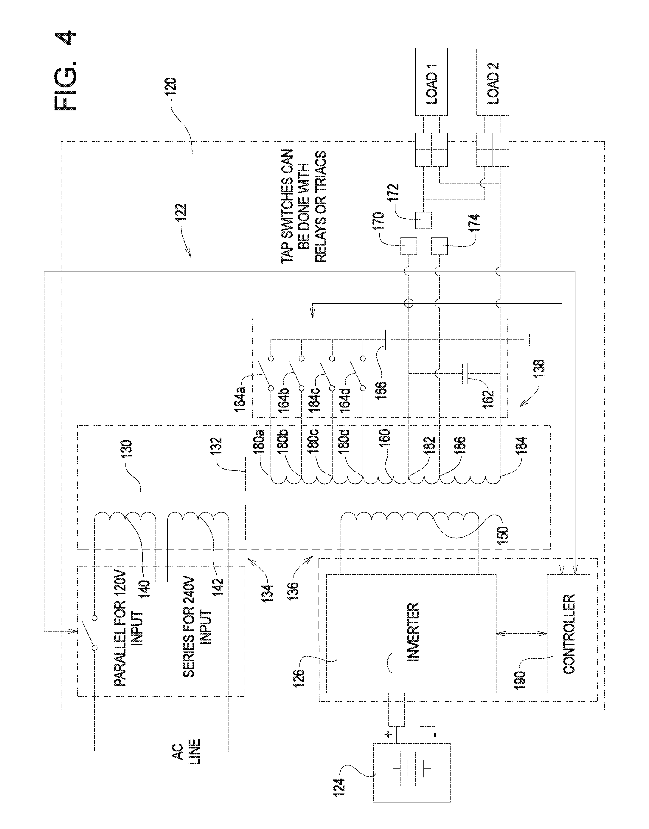
FIG. 4 is a block diagram of a first example uninterruptible power supply incorporating the first example ferroresonant transformer of FIG. 1.
DETAILED DESCRIPTION
Referring to FIG. 1 of the drawing, depicted therein is a first example ferroresonant transformer system 20 of the present invention. The first example ferroresonant transformer system 20 comprises a ferroresonant transformer 22 comprising a core 30 and a shunt 32. In the following discussion, certain reference characters will be used herein to refer to both a type of element and a specific one of that type of element. Letters will be appended to such reference characters when the reference character refers to a specific element.
In the first example ferroresonant transformer system 20, the shunt 32 is arranged relative to the core 30 to define a primary side comprising an input section 34 and a secondary side comprising an inverter section 36 and an output section 38 of the ferroresonant transformer 22. The input section 34 comprises first and second input windings 40 and 42. The inverter section comprises 36 comprises an inverter winding 50. The output section 38 comprises a tank winding 60, an output capacitor 62, a plurality of switches 64, a resonant capacitor 66, and output terminals 70 and 72. Optionally, an alternative output terminal 74 may be used.
The switches 64 are each operably connectable between one of a plurality of switch tap locations 80 of the tank winding 60 and the resonant capacitor 66. The output terminals 70 and 72 are connected to output tap locations 82 and 84 of the tank winding 60. Optionally, an alternative output tap 86 may be used.
The example output section 38 comprises four switches 64a, 64b, 64c, and 64d and four switch tap locations 80a, 80b, 80c, and 80d, although more or fewer switches 64 and switch tap locations 80 may be used. Typically, a plurality (two or more) of the switches 64 are used to implement tap switching. The example switches 64 can be triacs or mechanical relays.
A controller 90 is configured to control the switches 64. In general, the example controller 90 controls the switches 64 based on an output voltage, an output current, and an input voltage as will be described in further detail below.
In the first example ferroresonant transformer system 20 the first and second input windings 40 and 42 are connected in parallel for 120V input voltage and in series for 240V input voltage. As shown in FIG. 2, the first and second input windings 40 and 42 are connected in parallel to accommodate a 120V input. FIG. 3 shows that first and second input windings 40 and 42 are connected in series to accommodate a 240V input. The switch between parallel and series connection can be implemented such that the selection between 120V and 240V can easily be made in the field.
In particular, the example controller 90 operates the switches 64a, 64b, 64c, and 64d based on based on the output voltage, the output current, and the input voltage to optimize the operation of the transformer system 20 for a given set of operating conditions. The use of the switches 64a, 64b, 64c, and 64d to control the one of the taps 80a, 80b, 80c, and 80d to which the resonant capacitor 66 is connected allows a size of the ferroresonant transformer 22 to be kept to a minimum. The example controller 90 is configured such that the switches 64a, 64b, 64c, and 64d are configured to open and close when the AC current signal is at or near a zero crossing point and such that only one of the switches 64a, 64b, 64c, and 64d is effectively closed at any given point in time.
The first example ferroresonant transformer system 20 of the present invention thus implements tap switching on the ferro tank winding 60 of the output section 38 thereof. The first example ferroresonant transformer 20 thus implements tap switching at the output section 38 (e.g., the tank winding 60) instead of the input section 34.
FIG. 4 illustrates a first example uninterruptible power supply 120 incorporating a second example ferroresonant transformer system 122, a battery system 124, and an inverter 126.
The example ferroresonant transformer 122 forming part of the first example uninterruptible power supply 120 comprises a core 130 and a shunt 132. The example shunt 132 is arranged relative to the core 130 to define a primary side comprising an input section 134 and a secondary side comprising an inverter section 136 and an output section 138 of the ferroresonant transformer 122. The input section 134 comprises first and second input windings 140 and 142. The inverter section comprises 136 comprises an inverter winding 150. The output section 138 comprises a tank winding 160, an output capacitor 162, a plurality of switches 164, a resonant capacitor 166, and output terminals 170 and 172. Optionally, an alternative output terminal 174 may be used.
The switches 164 are each operably connectable between one of a plurality of switch tap locations 180 of the tank winding 160 and the resonant capacitor 166. The output terminals 170 and 172 are connected to output tap locations 182 and 184 of the tank winding 160. Optionally, an alternative output tap 186 may be used.
The example output section 138 comprises four switches 164a, 164b, 164c, and 164d and four switch tap locations 180a, 180b, 180c, and 180d, although more or fewer switches 164 and switch tap locations 180 may be used. Typically, a plurality (two or more) of the switches 164 are used to implement tap switching. The example switches 164 can be triacs or mechanical relays.
A controller 190 is configured to control the switches 164. In general, the example controller 190 controls the switches 164 based on an output voltage, an output current, and an input voltage as will be described in further detail below.
The first and second input windings 140 and 142 are connected in parallel for 120V input voltage (see, e.g., FIG. 2) and in series for 240V input voltage (see, e.g., FIG. 3). The switch between parallel and series connection can be implemented such that the selection between 120V and 240V can easily be made in the field.
In particular, the example controller 190 operates the switches 164a, 164b, 164c, and 164d based on based on the output voltage, the output current, and the input voltage to optimize the operation of the transformer system 122 for a given set of operating conditions. The use of the switches 164a, 164b, 164c, and 164d to control the one of the taps 180a, 180b, 180c, and 180d to which the resonant capacitor 166 is connected allows a size of the ferroresonant transformer 122 to be kept to a minimum. The example controller 190 is configured such that the switches 164a, 164b, 164c, and 164d are configured to open and close when the AC current signal is at or near a zero crossing point and such that only one of the switches 164a, 164b, 164c, and 164d is effectively closed at any given point in time.
The example uninterruptible power supply 120 normally operates in a line mode in which the example uninterruptible power supply 120 supplies power based on a line voltage present across one or both of the windings 140 and 142. The example inverter 126 is connected between the battery 124 and the inverter winding 150 to provide a source of DC power when the example uninterruptible power supply 120 is operating in a standby mode.
The first example uninterruptible power supply 120 incorporating a second example ferroresonant transformer system 122 thus implements tap switching on the ferro tank winding 160 of the output section 138 thereof. The second example ferroresonant transformer 122 thus implements tap switching at the output section 138 (e.g., the tank winding 160) instead of the input section 134.
By implementing tap switching at the output section (e.g., the tank winding 60 or 160 of output section 38 or 138) instead of the input section (e.g., 34 or 134), the first example ferroresonant transformer 20 and the first example uninterruptible power supply 120 comprising the second example ferroresonant transformer 122 provide the following benefits: 1. Simple dual input voltage windings configuration; 2. Ease of designing triac for tap switching devices with the high ferro inductance between input and output preventing huge utility current during tap switching; 3. High voltage tank winding allow the use of triac without losing efficiency due to high conduction loss between triac versus relay; 4. Cost reduction with low cost triac versus high cost relay; and 5. Improving the reliability with semiconductor triac versus mechanical relays.
The present invention may be implemented in forms other than those specifically described above, and the scope of the invention should be determined by the claims appended hereto and not the foregoing detailed descriptions of examples of the present invention.
* * * * *
References
D00000
D00001
D00002
D00003
D00004
XML
uspto.report is an independent third-party trademark research tool that is not affiliated, endorsed, or sponsored by the United States Patent and Trademark Office (USPTO) or any other governmental organization. The information provided by uspto.report is based on publicly available data at the time of writing and is intended for informational purposes only.
While we strive to provide accurate and up-to-date information, we do not guarantee the accuracy, completeness, reliability, or suitability of the information displayed on this site. The use of this site is at your own risk. Any reliance you place on such information is therefore strictly at your own risk.
All official trademark data, including owner information, should be verified by visiting the official USPTO website at www.uspto.gov. This site is not intended to replace professional legal advice and should not be used as a substitute for consulting with a legal professional who is knowledgeable about trademark law.