Traceable optical fiber cable and filtered viewing device for enhanced traceability
Bauco , et al. A
U.S. patent number 10,379,309 [Application Number 14/939,488] was granted by the patent office on 2019-08-13 for traceable optical fiber cable and filtered viewing device for enhanced traceability. This patent grant is currently assigned to Corning Optical Communications LLC. The grantee listed for this patent is CORNING OPTICAL COMMUNICATIONS LLC. Invention is credited to Anthony Sebastian Bauco, Douglas Llewellyn Butler.


| United States Patent | 10,379,309 |
| Bauco , et al. | August 13, 2019 |
Traceable optical fiber cable and filtered viewing device for enhanced traceability
Abstract
A system and method for tracing an optical communication cable and related traceable fiber optic cable are provided. The system includes a traceable optical communication cable that includes an elongate light emitting element extending along at least a portion of the length of the cable body configured to emit light radially outward from the cable body, and the light emitted from the light emitting element has a wavelength range. The cable body includes a plurality of spaced light transmitting windows separated from each other by a plurality of opaque fire-resistant sections. The system includes a viewing device having a light filtering element configured to pass light within the wavelength length range through the light filtering element and to block at least a portion of light having wavelengths outside of the wavelength range.
| Inventors: | Bauco; Anthony Sebastian (Horseheads, NY), Butler; Douglas Llewellyn (Painted Post, NY) | ||||||||||
|---|---|---|---|---|---|---|---|---|---|---|---|
| Applicant: |
|
||||||||||
| Assignee: | Corning Optical Communications
LLC (Hickory, NC) |
||||||||||
| Family ID: | 54705858 | ||||||||||
| Appl. No.: | 14/939,488 | ||||||||||
| Filed: | November 12, 2015 |
Prior Publication Data
| Document Identifier | Publication Date | |
|---|---|---|
| US 20160139353 A1 | May 19, 2016 | |
Related U.S. Patent Documents
| Application Number | Filing Date | Patent Number | Issue Date | ||
|---|---|---|---|---|---|
| 62081054 | Nov 18, 2014 | ||||
| Current U.S. Class: | 1/1 |
| Current CPC Class: | G01M 11/35 (20130101); F21V 33/00 (20130101); G02B 6/447 (20130101); G02B 27/022 (20130101); F21V 9/20 (20180201); G02B 6/4482 (20130101); G02B 6/3895 (20130101); G02B 6/001 (20130101); F21Y 2103/00 (20130101); F21Y 2115/20 (20160801) |
| Current International Class: | G02B 6/44 (20060101); G02B 27/02 (20060101); G01M 11/00 (20060101); F21V 33/00 (20060101); F21V 9/00 (20180101); F21V 8/00 (20060101); G02B 6/38 (20060101) |
References Cited [Referenced By]
U.S. Patent Documents
| 3942859 | March 1976 | Korodi |
| 4412936 | November 1983 | Khmelkov et al. |
| 4466697 | August 1984 | Daniel |
| 4557552 | December 1985 | Newton et al. |
| 4637686 | January 1987 | Iwamoto et al. |
| 4712858 | December 1987 | Presby |
| 4755018 | July 1988 | Heng et al. |
| 4763984 | August 1988 | Awai et al. |
| 4923274 | May 1990 | Dean |
| 4995691 | February 1991 | Purcell, Jr. |
| 5006806 | April 1991 | Rippingale et al. |
| 5017873 | May 1991 | Rippingale et al. |
| 5040867 | August 1991 | de Jong et al. |
| 5122750 | June 1992 | Rippingale et al. |
| 5179611 | January 1993 | Umeda et al. |
| 5206065 | April 1993 | Rippingale et al. |
| 5305405 | April 1994 | Emmons et al. |
| 5329348 | July 1994 | Nimura et al. |
| 5333228 | July 1994 | Kingstone |
| 5377292 | December 1994 | Bartling et al. |
| 5394496 | February 1995 | Caldwell et al. |
| 5395362 | March 1995 | Sacharoff et al. |
| 5432876 | July 1995 | Appeldorn et al. |
| 5463706 | October 1995 | Dumont et al. |
| 5500913 | March 1996 | Allen et al. |
| 5591160 | January 1997 | Reynard |
| 5666453 | September 1997 | Dannenmann |
| 5741152 | April 1998 | Boutros |
| 5764043 | June 1998 | Czosnowski et al. |
| 5835654 | November 1998 | Bergmann |
| 5979188 | November 1999 | Ojha |
| 5982967 | November 1999 | Mathis et al. |
| 6126325 | October 2000 | Yamane et al. |
| 6137928 | October 2000 | Albrecht |
| 6137935 | October 2000 | Bohme et al. |
| 6173097 | January 2001 | Throckmorton et al. |
| 6257750 | July 2001 | Strasser et al. |
| 6293081 | September 2001 | Grulick et al. |
| 6301418 | October 2001 | Freier |
| 6311000 | October 2001 | Schneider |
| 6314713 | November 2001 | Fitz et al. |
| 6317553 | November 2001 | Harper, Jr. et al. |
| 6347172 | February 2002 | Keller et al. |
| 6356690 | March 2002 | McAlpine et al. |
| 6379054 | April 2002 | Throckmorton et al. |
| 6388194 | May 2002 | Ryeczek |
| 6403947 | June 2002 | Hoyt |
| 6425694 | July 2002 | Szilagyi et al. |
| 6439780 | August 2002 | Mudd et al. |
| 6456768 | September 2002 | Boncek et al. |
| 6456785 | September 2002 | Evans |
| 6471412 | October 2002 | Belenkiy et al. |
| 6519396 | February 2003 | Schneider et al. |
| 6526200 | February 2003 | Davie |
| 6532328 | March 2003 | Kline |
| 6554485 | April 2003 | Beatty et al. |
| 6560390 | May 2003 | Grulick et al. |
| 6577243 | June 2003 | Dannenmann et al. |
| 6596943 | July 2003 | Ward |
| 6606431 | August 2003 | Unsworth |
| 6678449 | January 2004 | Thompson et al. |
| 6695491 | February 2004 | Leeman et al. |
| 6704479 | March 2004 | Koplow |
| 6710254 | March 2004 | Yueh |
| 6712524 | March 2004 | Beatty et al. |
| 6728453 | April 2004 | Petryszak |
| 6798956 | September 2004 | Morrison |
| 6816661 | November 2004 | Barnes et al. |
| 6823120 | November 2004 | Hurley |
| 6876809 | April 2005 | Sonderegger et al. |
| 6906505 | June 2005 | Brunet et al. |
| 6933438 | August 2005 | Watts et al. |
| 6969273 | November 2005 | Chen |
| 6979223 | December 2005 | Chen |
| 7020369 | March 2006 | Lodge, Jr. |
| 7029137 | April 2006 | Lionetti et al. |
| 7038135 | May 2006 | Chan et al. |
| 7049937 | May 2006 | Zweig et al. |
| 7090411 | August 2006 | Brown |
| 7121707 | October 2006 | Currie et al. |
| 7164819 | January 2007 | Jenson |
| 7217152 | May 2007 | Xin et al. |
| 7221284 | May 2007 | Scherer et al. |
| 7242831 | July 2007 | Fee |
| 7313304 | December 2007 | Andrews et al. |
| 7401961 | July 2008 | Longatti |
| 7406231 | July 2008 | Beck et al. |
| 7433565 | October 2008 | Joseph et al. |
| 7524082 | April 2009 | North |
| 7544909 | June 2009 | Dhir |
| 7572066 | August 2009 | De Jong et al. |
| 7596293 | September 2009 | Isenhour et al. |
| 7603020 | October 2009 | Wakileh et al. |
| 7618175 | November 2009 | Hulse |
| 7620279 | November 2009 | Joseph |
| 7653277 | January 2010 | Andrews et al. |
| 7671279 | March 2010 | Yin |
| 7748860 | July 2010 | Brunet |
| 7817884 | October 2010 | Demeritt et al. |
| 7920764 | April 2011 | Kewitsch |
| 7932805 | April 2011 | Darr et al. |
| 7948226 | May 2011 | Rathbun, II et al. |
| 8000576 | August 2011 | Chen et al. |
| 8102169 | January 2012 | Law et al. |
| 8150227 | April 2012 | Kewitsch |
| 8152385 | April 2012 | De Jong et al. |
| 8167471 | May 2012 | Moritz |
| 8314603 | November 2012 | Russell |
| 8322871 | December 2012 | Knaggs et al. |
| 8331752 | December 2012 | Biribuze et al. |
| 8408029 | April 2013 | De Angelis et al. |
| 8414319 | April 2013 | Patel et al. |
| 8428405 | April 2013 | Kewitsch |
| 8492448 | July 2013 | Dewa et al. |
| 8509579 | August 2013 | Martin-Lopez |
| 8545076 | October 2013 | Bickham et al. |
| 8548293 | October 2013 | Kachmar |
| 8582939 | November 2013 | Gimblet et al. |
| 8582940 | November 2013 | Abernathy et al. |
| 8591087 | November 2013 | Bickham et al. |
| 8620123 | December 2013 | Dean, Jr. et al. |
| 8620125 | December 2013 | Button et al. |
| 8683827 | April 2014 | De Angelis et al. |
| 8708724 | April 2014 | Patel et al. |
| 8724842 | May 2014 | Sumitani et al. |
| 8724942 | May 2014 | Logunov et al. |
| 8770525 | July 2014 | Donaldson et al. |
| 8787717 | July 2014 | Logunov |
| 8791829 | July 2014 | Gustafsson |
| 8798419 | August 2014 | Wessels, Jr. et al. |
| 8805141 | August 2014 | Fewkes |
| 8896286 | November 2014 | Abuelsaad et al. |
| 8896287 | November 2014 | Abuelsaad et al. |
| 8897612 | November 2014 | Logunov |
| 8903212 | December 2014 | Kachmar |
| 8909013 | December 2014 | Jiang et al. |
| 8929703 | January 2015 | Logunov |
| 9025923 | May 2015 | Logunov et al. |
| 9073243 | July 2015 | Gimblet et al. |
| 9146347 | September 2015 | Logunov et al. |
| 9182561 | November 2015 | Bauco et al. |
| 9196975 | November 2015 | Scherer et al. |
| 9271709 | March 2016 | Grey et al. |
| 9304278 | April 2016 | Bauco et al. |
| 9388975 | July 2016 | Wenger |
| 9429731 | August 2016 | Bookbinder et al. |
| 9435713 | September 2016 | Collier et al. |
| 9448380 | September 2016 | Mogensen |
| 9507096 | November 2016 | Isenhour et al. |
| 9529167 | December 2016 | Wu |
| 9541694 | January 2017 | Tissot |
| 9671551 | June 2017 | Dean, Jr. |
| 9709750 | July 2017 | Kuang et al. |
| 2001/0002220 | May 2001 | Trockmorton et al. |
| 2001/0048797 | December 2001 | Van Dijk et al. |
| 2002/0009282 | January 2002 | Grulick et al. |
| 2002/0036775 | March 2002 | Wolleschensky |
| 2002/0037133 | March 2002 | Unsworth |
| 2002/0136497 | September 2002 | McGarry et al. |
| 2002/0159735 | October 2002 | Edvold et al. |
| 2002/0185299 | December 2002 | Giebel |
| 2003/0002830 | January 2003 | Petryszak |
| 2003/0016924 | January 2003 | Thompson et al. |
| 2003/0108270 | June 2003 | Brimacombe et al. |
| 2003/0206519 | November 2003 | Sanders et al. |
| 2003/0222786 | December 2003 | Dannenmann et al. |
| 2004/0022504 | February 2004 | Hurley et al. |
| 2004/0052473 | March 2004 | Seo et al. |
| 2004/0146254 | July 2004 | Morrison |
| 2004/0160774 | August 2004 | Lionetti et al. |
| 2004/0179777 | September 2004 | Buelow, II et al. |
| 2004/0196648 | October 2004 | Franklin et al. |
| 2005/0052174 | March 2005 | Angelo et al. |
| 2005/0089284 | April 2005 | Ma |
| 2005/0212503 | September 2005 | Deibele |
| 2006/0104578 | May 2006 | Herbst |
| 2006/0133750 | June 2006 | Lee |
| 2006/0140562 | June 2006 | Joseph et al. |
| 2006/0193575 | August 2006 | Greenwood et al. |
| 2006/0232385 | October 2006 | Scherer et al. |
| 2006/0285350 | December 2006 | Wang |
| 2007/0116402 | May 2007 | Slade et al. |
| 2007/0153508 | July 2007 | Nall et al. |
| 2007/0217749 | September 2007 | Jong et al. |
| 2008/0080820 | April 2008 | Andrews et al. |
| 2008/0087082 | April 2008 | Andrews et al. |
| 2008/0121171 | May 2008 | Hulsey |
| 2008/0198618 | August 2008 | North |
| 2008/0204235 | August 2008 | Cook |
| 2008/0273844 | November 2008 | Kewitsch |
| 2009/0027873 | January 2009 | Tarlton |
| 2009/0297104 | December 2009 | Kachmar |
| 2009/0299440 | December 2009 | Slatkine |
| 2010/0021114 | January 2010 | Chen et al. |
| 2010/0066254 | March 2010 | Ott et al. |
| 2010/0148747 | June 2010 | Rathbun, II et al. |
| 2010/0166374 | July 2010 | Lapp |
| 2010/0274235 | October 2010 | Mihajlovic et al. |
| 2011/0034068 | February 2011 | Russell |
| 2011/0085776 | April 2011 | Biribuze et al. |
| 2011/0103747 | May 2011 | Chang et al. |
| 2011/0103757 | May 2011 | Alkemper et al. |
| 2011/0122646 | May 2011 | Bickham et al. |
| 2011/0150488 | June 2011 | Kewitsch |
| 2011/0305035 | December 2011 | Bickham et al. |
| 2012/0019900 | January 2012 | Kitson et al. |
| 2012/0219259 | August 2012 | Kewitsch |
| 2012/0275178 | November 2012 | Logunov |
| 2012/0275180 | November 2012 | Button et al. |
| 2012/0275745 | November 2012 | Logunov |
| 2013/0021597 | January 2013 | Carlson, Jr. et al. |
| 2013/0088888 | April 2013 | Fewkes et al. |
| 2013/0107565 | May 2013 | Genier |
| 2013/0201001 | August 2013 | Ratnakar |
| 2013/0209045 | August 2013 | Dean, Jr. et al. |
| 2013/0272014 | October 2013 | Logunov et al. |
| 2013/0341922 | December 2013 | Jimenez Buendia |
| 2014/0016904 | January 2014 | Kachmar |
| 2014/0070639 | March 2014 | Tamura |
| 2014/0221763 | August 2014 | Vayser et al. |
| 2014/0227438 | August 2014 | Dean, Jr. et al. |
| 2014/0270639 | September 2014 | James, III et al. |
| 2014/0355295 | December 2014 | Kuchinisky |
| 2014/0363134 | December 2014 | Bookbinder et al. |
| 2015/0043875 | February 2015 | Bookbinder et al. |
| 2015/0049992 | February 2015 | Bauco |
| 2015/0369986 | December 2015 | Logunov et al. |
| 2016/0139353 | May 2016 | Bauco et al. |
| 2016/0202418 | July 2016 | Fortin et al. |
| 2016/0231521 | August 2016 | Smith et al. |
| 2016/0313483 | October 2016 | Chomycz |
| 2016/0313513 | October 2016 | Wijbrans et al. |
| 2016/0377818 | December 2016 | Tong et al. |
| 2017/0207585 | July 2017 | Butler et al. |
| 2017/0293102 | October 2017 | Bauco et al. |
| 2018/0128996 | May 2018 | Sawicki et al. |
| 200941319 | Aug 2007 | CN | |||
| 201419706 | Mar 2010 | CN | |||
| 102589728 | Jul 2012 | CN | |||
| 201305952 | Jul 2012 | CN | |||
| 203241575 | Oct 2013 | CN | |||
| 4413597 | Oct 1995 | DE | |||
| 10239602 | Feb 2004 | DE | |||
| 102007025494 | Dec 2008 | DE | |||
| 102009015263 | Oct 2010 | DE | |||
| 202015007044 | Dec 2015 | DE | |||
| 0874191 | Oct 1998 | EP | |||
| 0952589 | Oct 1999 | EP | |||
| 1168025 | Jan 2002 | EP | |||
| 2113969 | Nov 2009 | EP | |||
| 2260198 | Apr 1993 | GB | |||
| 2375898 | Nov 2002 | GB | |||
| 57011305 | Jun 1980 | JP | |||
| 59182404 | Apr 1983 | JP | |||
| 61139221 | Jun 1986 | JP | |||
| 61161827 | Oct 1986 | JP | |||
| 1990055506 | Feb 1990 | JP | |||
| 2108007 | Apr 1990 | JP | |||
| 2108008 | Apr 1990 | JP | |||
| 6017157 | Mar 1994 | JP | |||
| 06130253 | May 1994 | JP | |||
| 9178956 | Jul 1997 | JP | |||
| 9237524 | Sep 1997 | JP | |||
| 2008153030 | Jul 2008 | JP | |||
| 2009244288 | Oct 2009 | JP | |||
| 2010237233 | Oct 2010 | JP | |||
| 2013196960 | Sep 2013 | JP | |||
| 875507 | Dec 2008 | KR | |||
| 1998034144 | Aug 1998 | WO | |||
| 1999024856 | May 1999 | WO | |||
| 2000011484 | Mar 2000 | WO | |||
| 2005106899 | Nov 2005 | WO | |||
| 2006044177 | Apr 2006 | WO | |||
| 2006113114 | Oct 2006 | WO | |||
| 2007053371 | May 2007 | WO | |||
| 2008048955 | Apr 2008 | WO | |||
| 2010011299 | Jan 2010 | WO | |||
| 2010021896 | Feb 2010 | WO | |||
| 2011063214 | May 2011 | WO | |||
| 2013055842 | Apr 2013 | WO | |||
| 2013059811 | Apr 2013 | WO | |||
| 2013122825 | Aug 2013 | WO | |||
| 2014026300 | Feb 2014 | WO | |||
| 2015000194 | Jan 2015 | WO | |||
| 2016170172 | Oct 2016 | WO | |||
Other References
|
Espacenet English machine translation of Rund et al. (DE 10239602 B3, cited in IDS of Jun. 8, 2016). cited by examiner . International Search Report and Written Opinion PCT/US2016/042414 dated Oct. 5, 2016. cited by applicant . U.S. Appl. No. 62/193,638, U.S. Appl. No. 62/221,769--Listed in ID as 26113. cited by applicant . U.S. Appl. No. 14/791,924, filed May 20, 2015. cited by applicant . U.S. Appl. No. 15/000,128, filed Jan. 19, 2016. cited by applicant . U.S. Appl. No. 15/054,380, filed Mar. 31, 2015. cited by applicant . U.S. Appl. No. 15/142,853, filed Apr. 29, 2016. cited by applicant . U.S. Appl. No. 62/193,638, filed Jul. 17, 2015. cited by applicant . U.S. Appl. No. 62/193,643, filed Jul. 17, 2015. cited by applicant . U.S. Appl. No. 62/221,769, filed Sep. 22, 2015. cited by applicant . U.S. Appl. No. 62/221,774, filed Sep. 22, 2015. cited by applicant . U.S. Appl. No. 62/248,490, filed Oct. 30, 2015. cited by applicant . International Search Report and Written Opinion PCT/US2016/020542 dated Jun. 7, 2016. cited by applicant . "Side Emitting Super Glowing Fiber," MeshTel.com. MeshTel-INTELITE, Inc., 1996-2012. Web. Aug. 1, 2013. cited by applicant . International Search Report and Written Opinion PCT/US2016/031624 dated Aug. 31, 2016. cited by applicant . http://www.dexim.net/list.php?id=7, Dexim product reference, downloaded from the web Feb. 24, 2016. 2 pages. cited by applicant . Kremenakova, et al., "Characterizaion of Side EmmittingPolymeric Optical Fibres," Jounal of Fiber Bioengineering & Informatics 5:4 (2012) pp. 423-431, http://www.jfbi.org, Dec. 2012. cited by applicant . Fiber Optic Products, Inc., "Specifications of our Fiber and Cable," n.d. Retrieved on Aug. 9, 2013, 2 pages. cited by applicant . M. Rajesh, "Polymer Photonics: An Overview," Fabrication and Characterisation, 2011, 38 pages. cited by applicant . Schott, "SpectraStream Glass Harnesses," Rev. Nov. 2006, 2 pages. cited by applicant . Spigulis, J., "Side-Emitting Fibers Brighten Our World in New Ways," Oct. 2005, Retrieved from www.osa-opn.org, 6 pages. cited by applicant . Patent Cooperation Treaty, International Search Report, Application No. PCT/US2013/025262, Jul. 16, 2013, 7 pages. cited by applicant . "Super Vision Fiber Optics Side Glow Cables," TriN01ihLighting,com, Tri North Lighting, Inc., n.d., Web. Aug. 1, 2013. cited by applicant . U.S. Appl. No. 13/431,565, filed Mar. 27, 2012, David L. Dean, Jr., 32 pages. cited by applicant . European Search Report, Application No. 15168466.9-1553, Dec. 17, 2015, 9 pages. cited by applicant . Optical fiber with nanostructured cladding ofTi02 nanoparticles self-assembled onto a side polished fiber and its temperature sensing, Lu et al., Optics Express, vol. 22, No. 26, Dec. 29, 2014, 7 pages, downloaded from internet on Jan. 5, 2015. cited by applicant . Patent Cooperation Treaty, International Search Report for PCT/US2015/060558, dated Feb. 9, 2016, 5 pages. cited by applicant . Patent Cooperation Treaty International Search Report, Application No. PCT/US2014/049524, Jan. 20, 2015, 5 pages. cited by applicant . "Diode Lasers, Fiber Optics, IR, Red, Green, Blue Diode Lasers, Laser Diode, Fiber Illuminators, Fiber Optics, Coupler, Galvonarneters, Laser Show Acessories," Jan. 1, 2013, httn://www.meshtel.com/, 1 oage. cited by applicant . Patent Cooperation Treaty, International Search Report, PCT/US2014/049525, dated Jan. 23, 2015, 18 pages. cited by applicant . U.S. Appl. No. 14/295,844, Bookbinder filed Jun. 4, 2014, 25 pages. cited by applicant . Patent Cooperation Treaty, International Search Report and Written Opinion for International Application No. PCT/US2014/041510, dated Sep. 18, 2014, 10 pages. cited by applicant . International Searching Authority Invitation to Pay Additional Fees PCT/US2016/055497 dated Dec. 19, 2016. cited by applicant . International Searching Authority Invitation to Pay Additional Search Fees PCT/US2016/042416 dated Oct. 7, 2016. cited by applicant . International Search Report and Written Opinion PCT/US2017/012899 dated Mar. 9, 2017. cited by applicant . Endruweit et al. "Spectroscopic experiments regarding the effciency of side emission optical fibres in the UV-A and visible blue spectrum" Optics and Lasers in Engineering 46 (2008) pp. 97-105. cited by applicant. |
Primary Examiner: Amara; Mohamed K
Attorney, Agent or Firm: Weeks; Adam R.
Parent Case Text
PRIORITY APPLICATION
This application claims the benefit of priority under 35 U.S.C. .sctn. 119 of U.S. Provisional Application Ser. No. 62/081,054, filed on Nov. 18, 2014, the content of which is relied upon and incorporated herein by reference in its entirety.
Claims
What is claimed is:
1. A system for tracing an optical communication cable, the system comprising: a traceable optical communication cable comprising: a cable body including a first end, a second end, an outer surface, an inner surface, and a channel defined by the inner surface and extending a length between the first end and the second end; an optical communication element located in the channel; and an elongate light emitting element extending along at least a portion of the length of the cable body, wherein the cable body comprises a plurality of light transmitting windows spaced periodically along the length of the cable body, wherein the light emitting element passes through the plurality of light transmitting windows, wherein the cable body includes a plurality of opaque sections located between adjacent light transmitting windows, wherein the light emitting element passes through the plurality of opaque sections, wherein the plurality of light transmitting windows are formed from a light transmitting polymer material; and a viewing device having a light filtering element configured to pass light within a wavelength range through the light filtering element and to block at least a portion of light having wavelengths outside of the wavelength range.
2. The system of claim 1 further comprising a tracing light generating device configured to be coupled to the light emitting element and to energize the light emitting element causing light to be emitted from the light emitting element.
3. The system of claim 2 wherein the light emitting element is a light diffusing optical fiber and the tracing light generating device includes a laser generating light in the wavelength range.
4. The system of claim 3 wherein the laser is configured to generate light having a wavelength range of at least one of 443 nm to 447 nm, 518 nm to 522 nm, 530 nm to 534 nm, or 615 nm to 660 nm, and the light filtering element is a band-pass filter configured to pass light having a wavelength within plus or minus 5 nm of the wavelength range.
5. The system of claim 2 wherein the light emitting element is an electroluminescent wire and the tracing light generating device includes an electrical power supply configured to supply current to the electroluminescent wire.
6. The system of claim 2 wherein the tracing light generating device is configured to power the light emitting element such that the light emitted from the light emitting element is emitted in a pulsating pattern.
7. The system of claim 1 wherein the viewing device includes glasses including the light filtering element.
8. The system of claim 1 wherein the viewing device includes a digital camera including the light filtering element.
9. The system of claim 1 wherein the plurality of light transmitting windows comprise spaced rings extending circumferentially around the cable body.
10. The system of claim 1 wherein the cable body comprises a cable jacket and the plurality of light transmitting windows extend from an outer surface of the cable jacket partially through the cable jacket.
11. The system of claim 1 wherein: the plurality of light transmitting windows comprise spaced rings extending circumferentially around the cable body; and the cable body comprises a cable jacket and the plurality of light transmitting windows extend from an outer surface of the cable jacket partially through the cable jacket.
12. An optical communication cable for use with a system for tracing the optical communication cable comprising: a cable body including a first end, a second end, an outer surface, an inner surface, and a channel defined by the inner surface and extending a length between the first end and the second end; an optical communication element located in the channel; an elongate light emitting element extending along at least a portion of the length of the cable body; and a plurality of light transmitting windows spaced periodically along the length of the cable body, wherein the light emitting element passes through the plurality of light transmitting windows, wherein the cable body includes a plurality of opaque sections located between adjacent light transmitting windows, wherein the light emitting element passes through the plurality of opaque sections, wherein the plurality of light transmitting windows are formed from a light transmitting polymer material.
13. The optical communication cable of claim 12 further comprising a first optical connector coupled to the first end of the cable body and a second optical connector coupled to the second end of the cable body.
14. The optical communication cable of claim 12 wherein the light emitting element extends helically along the length of the cable body.
15. The optical communication cable of claim 12 wherein the light emitting element is a light diffusing optical fiber.
16. The optical communication cable of claim 12 wherein the light emitting element is an electroluminescent wire.
17. A traceable optical communication cable comprising: a cable body including a first end, a second end, an outer surface, an inner surface, and a channel defined by the inner surface and extending a length between the first end and the second end; an optical communication element located in the channel; and an elongate light emitting element extending along at least a portion of the length of the cable body and embedded in the cable body between the inner surface and the outer surface of the cable body; wherein the cable body includes a plurality of light transmitting windows spaced from each other along the length of the cable body, wherein the light emitting element passes through the plurality of light transmitting windows; wherein the cable body includes a plurality of opaque sections located between adjacent light transmitting sections, wherein the light emitting element passes through the plurality of opaque sections, and wherein the plurality of light transmitting windows are formed from a light transmitting polymer material.
18. The optical communication cable of claim 17, wherein the light emitting element extends helically along the length of the cable body.
19. A method of tracing a path of a first cable within a group of cables comprising: emitting light from an outer surface of a cable body of the first cable along at least a portion of a length of the first cable, wherein the emitted light has a wavelength range, wherein the cable body comprises a first end, a second end, the outer surface, an inner surface, and a channel defined by the inner surface and extending the length between the first end and the second end, wherein the cable body comprises a plurality of light transmitting windows spaced periodically along the length of the cable body, wherein a light emitting element passes through the plurality of light transmitting windows such that the light emitted from the outer surface of the cable body is transmitted out of the cable body through the plurality of light transmitting windows, wherein the cable body includes a plurality of opaque sections located between adjacent light transmitting windows, wherein the light emitting element passes through the plurality of opaque sections, wherein the plurality of light transmitting windows are formed from a light transmitting polymer material; filtering light within the wavelength range from ambient light; and detecting the filtered light to identify the first cable within the group of cables.
20. The method of claim 19 wherein the emitting light step includes generating laser light within the wavelength range, and providing the laser light into a light diffusing optical fiber embedded within the cable body of the first cable.
21. The method of claim 19 wherein the emitting light step includes supplying electrical power to an electroluminescent wire embedded within the cable body of the first cable, wherein the powered electroluminescent wire generates the light within the wavelength range.
22. The method of claim 19 wherein the filtering step includes using glasses including a band-pass filter that passes a greater amount of light within the wavelength range than light outside of the wavelength range, and the detecting step includes viewing the first cable and the emitted light through the glasses.
23. The method of claim 19 wherein the filtering step includes imaging the cable body with a digital camera that includes a band-pass filter that passes a greater amount of light within the wavelength range than light outside of the wavelength range, and the detecting step includes viewing the first cable and the emitted light through the digital camera.
Description
BACKGROUND
The disclosure relates generally to cables and more particularly to optical communication cables including an embedded element that emits light along the exterior of the cable. The disclosure also relates to light filtering viewing devices that enhance the visibility of the cable during tracing and to methods of tracing the path of such an optical communication cable within a group of cables.
Optical communication cables have seen increased use in a wide variety of electronics and telecommunications fields. Fiber optic cable assemblies may range in size and complexity from single-fiber jumpers to multi-fiber harnesses. These cable assemblies are typically used to interconnect equipment in high-speed networks, and within some high-speed networks, a large number of multiple individual cables (e.g., fiber optic patchcords) are used to interconnect various equipment, for example, within a telecommunications closet, server room, etc. As the needs of the network change or as repairs are needed, network operators frequently desire to change, move or replace cables with the network.
SUMMARY
One embodiment of the disclosure relates to a system for tracing an optical communication cable. The system includes a traceable optical communication cable. The traceable optical communication cable includes a cable body having a first end, a second end, an outer surface, an inner surface, and a channel defined by the inner surface and extending between the first end and the second end. The traceable optical communication cable includes an optical communication element located in the channel. The traceable optical communication cable includes an elongate light emitting element extending along at least a portion of the length of the cable body. The light emitting element is configured to emit light radially outward from the cable body, and the light emitted from the light emitting element has a wavelength range. The system includes a viewing device having a light filtering element configured to pass light within the wavelength length range through the light filtering element and to block at least a portion of light having wavelengths outside of the wavelength range.
Another embodiment of the disclosure relates to an optical communication cable for use with a system for tracing the optical communication cable. The optical communication cable includes a cable body including a first end, a second end, an outer surface, an inner surface, and a channel defined by the inner surface and extending between the first end and the second end. The optical communication cable includes an optical communication element located in the channel. The optical communication cable includes an elongate light emitting element extending along at least a portion of the length of the cable body configured to emit light along the length of the light emitting element, and light emitted from the light emitting element is visible from outside of the cable body. The optical communication cable includes a plurality of light transmitting windows spaced periodically along the length of the cable body and located in radial alignment with and radially outside of the light emitting element such that light emitted from the light emitting element is transmitted out of the cable body through the plurality of light transmitting windows. The cable body includes a plurality of opaque sections located between adjacent light transmitting windows along the length of the cable body, and the opaque sections include a fire-resistant polymer material.
An additional embodiment of the disclosure relates to a traceable optical communication cable. The traceable optical communication cable includes a cable body including a first end, a second end, an outer surface, an inner surface, and a channel defined by the inner surface and extending between the first end and the second end. The traceable optical communication cable includes an optical communication element located in the channel. The traceable optical communication cable includes an elongate light emitting element extending along at least a portion of the length of the cable body and embedded in the cable body below the outer surface and outside of the channel. The cable body includes a plurality of light transmitting windows spaced from each other along the length of the cable body and located in radial alignment with and radially outside of the light emitting element such that light emitted from the light emitting element is transmitted out of the cable body through the plurality of light transmitting windows. The cable body includes a plurality opaque sections located between adjacent light transmitting windows along the length of the cable body, and the opaque sections include a fire-resistant polymer material.
An additional embodiment of the disclosure relates to a method of tracing a path of a first cable within a group of cables. The method includes emitting light from an outer surface of the first cable along at least a portion of the length of the first cable, and the emitted light has a wavelength range. The method includes filtering light within the wavelength range from ambient light. The method includes detecting the filtered light to identify the first cable within the group of cables.
Additional features and advantages will be set forth in the detailed description which follows, and in part will be readily apparent to those skilled in the art from the description or recognized by practicing the embodiments as described in the written description and claims hereof, as well as the appended drawings.
It is to be understood that both the foregoing general description and the following detailed description are merely exemplary and are intended to provide an overview or framework to understand the nature and character of the claims.
The accompanying drawings are included to provide a further understanding and are incorporated in and constitute a part of this specification. The drawings illustrate one or more embodiment(s), and together with the description serve to explain principles and operation of the various embodiments.
BRIEF DESCRIPTION OF THE DRAWINGS
FIG. 1 is a perspective view of an equipment rack supporting fiber optic cables.
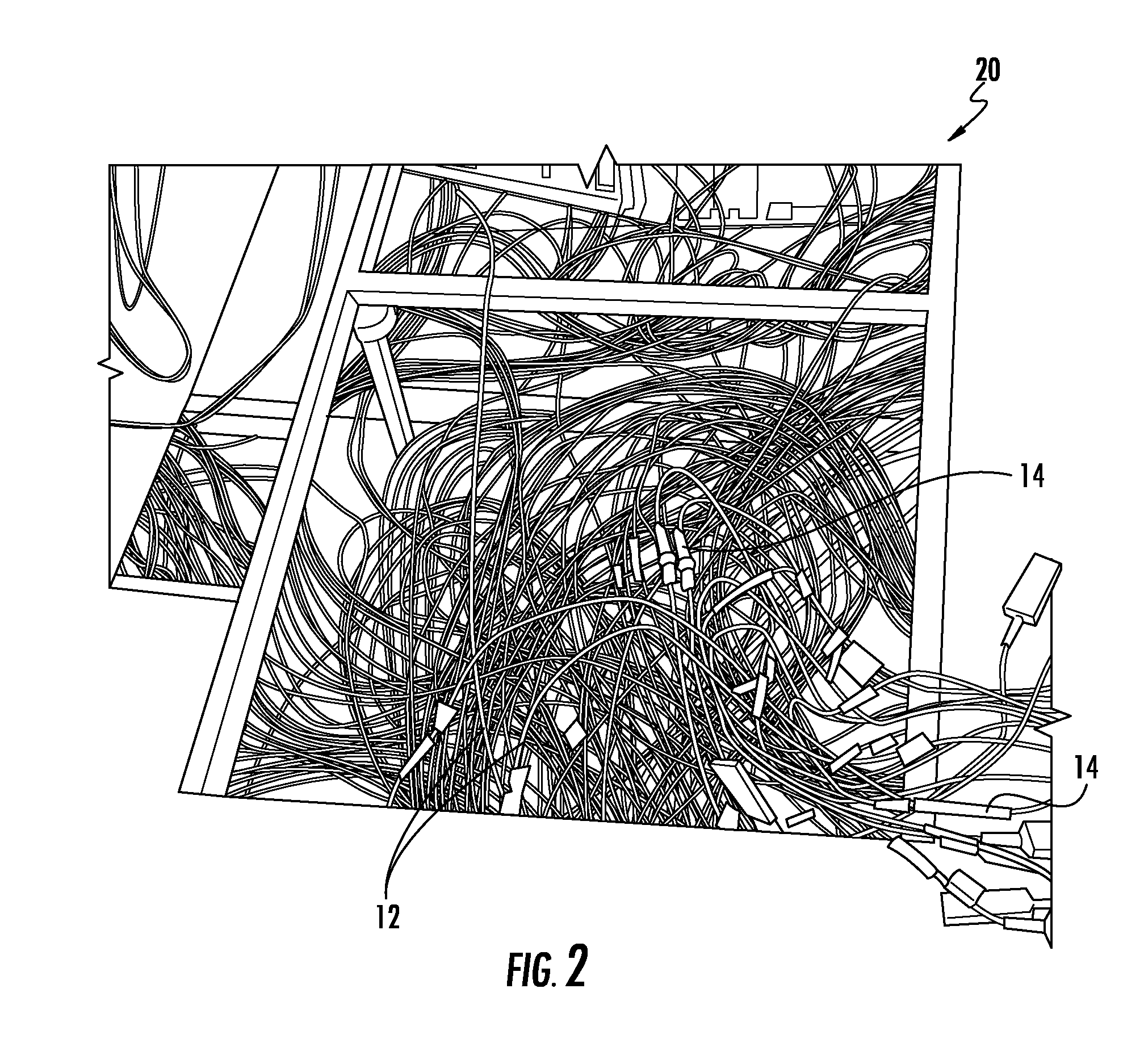
FIG. 2 is a perspective view of an under-floor cable tray supporting fiber optic cables.
FIG. 3 is a cross-sectional view of a traceable optical fiber cable according to an exemplary embodiment.
FIG. 4 is a side view of the traceable optical fiber cable of FIG. 3 according to an exemplary embodiment.
FIG. 5 is a cross-sectional view of a light emitting element for a traceable fiber optic cable according to an exemplary embodiment.
FIG. 6 is a block diagram of the tracing tool according to an exemplary embodiment.
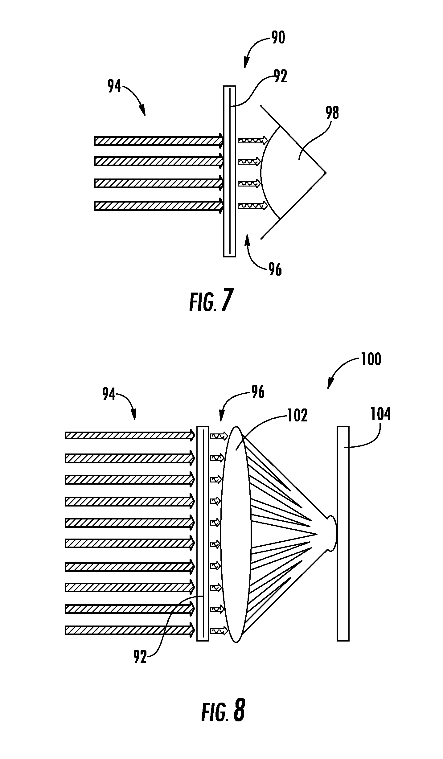
FIG. 7 is a schematic view of a viewing device that facilitates detection of the light emitted from a traceable fiber optic cable according to an exemplary embodiment.
FIG. 8 is a schematic view of a viewing device that facilitates detection of the light emitted from a traceable fiber optic cable according to another exemplary embodiment.
DETAILED DESCRIPTION
Referring generally to the figures, various embodiments of a system and method for tracing an optical communication cable and related traceable fiber optic cable are shown. In addition various embodiments of a cable, e.g., an optical communication cable, including an elongate light emitting element are shown. In various embodiments, the elongate light emitting element is a light diffusing optical fiber (LDF) or an electroluminescent wire (EL wire) that is located within the cable and runs substantially the entire length of the cable. The light emitting element, when connected to a light generating device that includes a light source (in the case of an LDF) or a power supply (in the case of an EL wire), emits light out from the cable along at least a portion of the cable. This emitted light allows a user, e.g., a network operator, to detect the light emitted along the length of the cable to identify a particular cable within groups or bundles of cables typical within many network installations. Because the light emitting element runs the entire length or substantially the entire length of the cable, the emitted light allows the entire length of the cable to be identified from the other cables within a group of cables allowing the network operator to more easily remove, repair, untangle, disconnect, etc. a particular cable from all of the other cables within the group.
In various embodiments, the light emitting element of the optical cable is configured to emit light with a relatively narrow and predetermined wavelength range. In various embodiments, the user may use a viewing device (such as glasses or a digital camera) that includes a light filtering element (e.g., a band-pass filter) that allows light within the wavelength range emitted from the light emitting element to pass through the filter while blocking at least some of the light (e.g., ambient light) that is outside of the wavelength range. This arrangement allows the user to more easily view the particular cable that has the energized light emitting element while using a relatively low powered power source to energize the light emitting element. Thus, by using the combination of a relatively narrow spectrum light emitting element and a light-filtering viewing device, identification of the desired optical cable is facilitated, even within brightly lit rooms or installations. In addition, this combination provides easy identification without the need to use high powered lasers or high current electrical power that may otherwise be needed to generate sufficient light to allow a traceable cable to be easily viewed in a bright environment.
In various embodiments, the light generating device when coupled to the light emitting element of the cable is configured to cause light to be emitted from the light emitting element in a way that improves the visibility of the light. For example, in some embodiments, the light generating device causes the light emitting element to emit light in a flashing or pulsing pattern. As compared to static illumination of a light emitting element, a flashing or pulsing pattern may further facilitate user identification of the cable having the illuminated light emitting element.
The light emitting element may be structured and arranged within the cable to provide good viewability. For example, the body of the cable may include a plurality of light transmitting (e.g., transparent, translucent, etc.) windows positioned to the exterior of the light emitting element. The windows allow light from the light emitting element to be visible from outside of the cable. In some embodiments, the light emitting element extends in a helical pattern within the cable body, and the windows are rings of clear material extending around the cable jacket. Additionally, in some embodiments, opaque sections of fire-resistant polymer material of the cable body are located between each window section. Because many translucent/transparent polymers are not fire-resistant, the fire-resistant polymer sections between each window limits the ability of flame to propagate down the length of the cable.
In many network environments, large numbers of cables are interconnected to a variety of communications or electronic equipment resulting in congestion that can make tracing the length of a particular cable difficult. In some network environments, cables (e.g., fiber optic patchcords) may be relatively long (e.g., between about 2 meters and 30 meters in length) such that identifying the ends and the length of a particular cable to be moved or replaced may be a labor intensive task typically involving two workers incrementally and manually tracing a particular cable from one end to the other. Thus, the cable embodiments of the present disclosure provide systems and methods that allow the identification of both ends of a cable and/or to also trace the length of the cable without the need for high powered illuminating tracing systems.
FIG. 1 shows an equipment rack 10, and a large number of cables, shown as fiber optic cables 12. FIG. 2 shows bundles of fiber optic cables 12 located in an under-floor cable tray 20. In both FIG. 1 and FIG. 2, fiber optic cables 12 include connectors 14 located at the ends of the cables. In FIG. 1, connectors 14 are shown attached to hardware, such as servers 16 supported by equipment rack 10, and in FIG. 2, connectors 14 are shown interconnecting cables 12 with other fiber optic cables. Fiber optic cables 12 may be legs of larger cable assemblies, such as harness cable assemblies or jumper cables extending from a furcation body coupled to a trunk cable. In other embodiments, cables 12 may be patchcords, e.g., fiber optic cables including one or more optical fiber, a cable body, and connectors on each end of the cable, to interconnect equipment within a network installation.
As can be seen in the exemplary network environments of FIG. 1 and FIG. 2, cables 12 can become congested making identification of the ends and the length of a particular fiber optic cable 12 difficult. The network operator may need to identify a particular optical fiber for a number of reasons, such as to replace a broken or malfunctioning cable, to move or add cables to accommodate changes in the network, to install new hardware, etc. Such identification may be particularly difficult in fiber optic network installations because of the relatively small diameter of the typical fiber optic cable (e.g., a fiber optic patchcord may have an outer diameter of about 2 mm or less).
Accordingly, to facilitate such activities, the tracing system and method and related cable embodiments discussed herein include a light emitting element that allows for identification of both ends of a particular cable as well as the length of the cable body. In particular, the light emitting element is configured to emit light along the length of a selected cable 12 within the group of cables, for example by coupling a light generating device to one end of the light emitting element. The light emitting element, once energized by the light generating device, emits light along the length of the cable. The user then views the cable emitting light allowing the path of the particular cable to be traced. In various embodiments discussed herein, the system includes a viewing device including a spectral filter that the user uses to view the illuminated cable such that background or ambient light is reduced, thereby enhancing the detectability of the illuminated cable. It should be understood that while the embodiments discussed herein relate primarily to fiber optic cables, in other embodiments, the light emitting element and cable tracing systems and methods discussed herein can be applied to other types of cables or conduits, such as electrical-communication wires, power lines, hydraulic-fluid lines, etc.
Referring to FIG. 3 and FIG. 4, a fiber optic cable 30 ("cable 30") is shown according to an exemplary embodiment. It should be understood that one or more cables 12 as shown in FIG. 1 and FIG. 2 may be configured as cable 30. Cable 30 includes one or more optical communication elements, shown as optical fibers 32, located within a cable body, shown as cable jacket 34. Cable 30 also includes a light emitting element 36. In various embodiments, light emitting element 36 may be a light diffusing optical fiber (LDF), a plastic optical fiber (POF), an electroluminescent wire (EL wire), or other suitable light emitting element. Optical fibers 32 may be tight-buffered optical fibers having one or more outer protective layers (e.g., polymer layers) surrounding optical fiber 32, which itself comprises a glass core, a glass cladding surrounding the glass core but having a higher refractive index, and an outer coating (e.g., an acrylic layer). In other embodiments, optical fibers 32 may be one of a plurality of glass optical fibers in a loose-tube arrangement, or alternatively, optical fibers 32 may be one of several glass optical fibers arranged in parallel within an optical fiber ribbon. In some embodiments, optical fibers 32 may be multi-core optical fibers. In other embodiments, a cable as disclosed herein may contain data transmission elements other than one or more optical fibers, such as copper wires, or other media.
Cable jacket 34 includes an inner surface 38 and an outer surface 40. Inner surface 38 defines a channel, shown as central cavity 42, and in the embodiment shown, outer surface 40 defines the exterior surface of cable 30. In the embodiment of FIG. 3, optical fibers 32 are located in central cavity 42, and in some embodiments, cable 30 may include one or more tensile strength elements, such as aramid yarn strands located within central cavity 42.
In various embodiments, cable jacket 34 may have a thickness between 0.3 mm and 5.0 mm. For example, the outer diameter of cable jacket 34 may be about 2 mm (e.g., 2 mm plus or minus 0.1 mm). In general, cable jacket 34 provides structure and protection to optical fibers 32 during and after installation. Cable jacket 34 may be formed from an extruded polymer material, and/or may include multiple layers of materials where the outermost layer defines outer surface 40 of cable jacket 34. Further, cable 30 may include one or more strengthening members embedded within the material of cable jacket 34 or located within cavity 42. For example, cable 30 may include an elongate strengthening member (e.g., a fiber or rod) located within cavity 42 and running the length of cable jacket 34, and that is formed from a material that is more rigid than the material of cable jacket 34. The strengthening members may be metal, braided steel, glass reinforced plastic, fiber glass, fiber glass yarns or other suitable material. In various embodiments, cable 30 may include a variety of other elements embedded in or surrounded by cable jacket 34 depending on the intended use of a particular cable 30, including armor layers, moisture barrier layers, rip cords, etc. Additionally, cable 30 may include other components such as steel armor and stranded and/or longitudinal strength elements. Cable 30 may be stranded, loose tube core cable construction, or other fiber optic cable construction.
In general, cable 30 is constructed such that light generated by light emitting element 36 is visible from the outside of cable 30. In the embodiment shown in FIGS. 3 and 4, a plurality of light transmitting windows 44 (e.g., translucent or transparent windows) are located radially between light emitting element 36 and outer surface 40 of cable 30. As shown in FIG. 4, cable 30 includes a plurality of light transmitting windows 44 spaced along the length of cable 30 that generally follow the path of light emitting element 36 within cable 30. Additionally, the material of light transmitting windows 44 defines the portion of outer surface 40 radially outside of light emitting element 36 and also extends from outer surface 40 radially inward to light emitting element 36, but does not extend all of the way through cable jacket 34 to cavity 42. In another embodiment, the material of light transmitting window does extend all of the way through the cable jacket between cavity 42 and outer surface 40. In these arrangements, the material of light transmitting windows defines a light transmitting path from the light emitting element 36 radially to the exterior of cable 30 such that light emitted from light emitting element 36 is visible from outside of cable 30.
Referring to FIG. 4, opaque sections 46 of cable body 34 are located between adjacent windows 44. In various embodiments, the majority of cable body 34, including opaque sections 46, are formed from one or more fire-resistant polymer material. Some clear plastic materials, such as that used to form windows 44, tend to have relatively low fire-resistant characteristics. Thus, opaque sections 46 provide sections of fire-resistant material located between adjacent windows 44 limiting the ability of a flame from spreading along the length of cable 30 by burning the materials of windows 44.
In various embodiments, the fire-resistant polymer material of cable body 34 and the light transmitting material of windows 44 are coextruded polymer materials. In such embodiments, cable body 34 and windows 44 are extruded around light emitting element 36 such that light emitting element 36 is embedded within cable body 34 and within windows 44. Windows 44 may be formed from a PVC material, and the rest of cable body 34 may be formed from a fire-resistant polymer material, such as fire-resistant PVC, medium density polyethylene, polypropylene, etc. Additionally, the fire-resistant polymer material of the majority of cable body 34 and of opaque sections 46 are an extrudable polymer material that includes one or more material, additive or component embedded in the polymer material that provides fire-resistant characteristics, such as relatively low heat generation, low heat propagation, low flame propagation, and low smoke production. The fire resistant material may include an intumescent material additive embedded in the polymer material. Alternatively, the fire resistant material includes a non-intumescent fire resistant material embedded in the polymer material, such as a metal hydroxide, aluminum hydroxide, magnesium hydroxide, etc., that produces water in the presence of heat/fire which slows or limits heat transfer through or along cable 30. In specific embodiments, the fire resistant material may be a low smoke zero halogen polymer material.
Windows 44 are sized and shaped to allow a sufficient amount of light to be seen from light emitting element 36. In addition, in some embodiments, the lengths of opaque sections 46 are sufficiently large to provide the fire resistance functionality noted above, while at the same time providing enough window area that the light from light emitting element 36 is visible.
In the embodiment shown in FIG. 4, a single light emitting element 36 extends along the length of the cable substantially parallel to cavity 42 and/or optical fibers 32. In other embodiments, cable 30 may include multiple light emitting elements 36 each located at a different circumferential position within cable body 34, and each light emitting element 36 may include its own set of windows 44 that extend along the length of the light emitting element. For example, in one embodiment, cable 30 includes three light emitting elements 36, each spaced approximately 120 degrees around cable body 34 from the adjacent light emitting element 34. In another embodiment, light emitting element 36 extends helically along the length of cable body 34, and, in this embodiment, windows 44 are spaced rings of the clear material extending circumferentially around cable body 34.
Referring to FIG. 5, light emitting element 36 is shown as a light diffusing optical fiber (LDF) 50 according to an exemplary embodiment. LDF 50 includes a fiber body 52, which may be formed from a UV fused silica material. LDF 50 also includes a plurality of scattering sites 54 located periodically along the length of LDF 50 and a clear exterior buffer coating 56. Scattering sites 54 scatter light from within LDF 50 such that some light passes out of fiber body 52 illuminating LDF 50. In various embodiments, LDF 50 is a relatively small diameter optical fiber. For example, the outer diameter of LDF 50 may be between 150 micrometers and 200 micrometers, and more specifically may be about 170 micrometers (e.g., 170 micrometers plus or minus 1%). In such embodiments, the small diameter of LDF 50 allows cable 30 to incorporate a light emitting element without the need to substantially increase the outer diameter of the cable jacket.
In another embodiment, light emitting element 36 is an electroluminescent wire (EL wire) that emits light when coupled to an electric power supply, typically an alternating current power supply. In various embodiments, the EL wire includes a conductor (e.g., a copper wire) surrounded by a phosphor material which emits light when current is delivered to the conductor. An outer colored layer of translucent plastic material may be used to control the color of light generated by the EL wire.
Referring generally to FIGS. 6-8, components of a system for tracing an optical communication cable, such as cable 30 is shown. Referring to FIG. 6, the system for tracing an optical communication cable includes a tracing light generating device, shown as tracing tool 70 according to an exemplary embodiment. In general, tracing tool 70 includes a housing 72 that includes the various electronics and power supplies needed to cause light emitting element 36 to emit light as discussed above. FIG. 6 shows a block diagram of tracing tool 70. In one embodiment, tracing tool 70 may include a power supply 78 (e.g., one or more batteries) and light generating control system 80. In general, light generating control system 80 includes hardware and/or software configured to cause light emitting element 36 to emit light under the control of tracing tool 70. Further, tracing tool 70 general may include a structure configured to couple tracing tool 70 to light emitting element 36 such that tracing tool 70 causes light emitting element 36 to emit light as discussed above
Light generating control system 80 will typically be configured based on the type of light emitting element 36 carried by cables 30 within a particular network installation. In embodiments in which light emitting element 36 is an LDF, light generating control system 80 includes a laser that generates light with a desired wavelength range and is configured to direct laser light from the laser of tracing tool 70 into light emitting element 36. As explained above, as the laser light travels down the LDF, portions of light are emitted outward from the LDF by interaction with scattering sites 54, such that light emitting element 36 is illuminated along the length of cable 30.
A wide variety of laser types and colors may be used within tracing tool 70. For example, the laser of tracing tool 70 may generate light within a selected wavelength range, such as at about 445 nm (e.g., 445 nm plus or minus 2 nm), at about 520 nm (e.g., 520 nm plus or minus 2 nm), at about 532 nm (e.g., 532 nm plus or minus 2 nm) or between 615 nm and 660 nm. In various embodiments, the laser of tracing tool 70 generates light in the green portion of the visual spectrum because green light may provide for better detected contrast within the typical network installation. In one embodiment, the laser of tracing tool 70 is a diode pumped solid state laser having a wavelength of between 530 nm and 534 nm, and more specifically of about 532 nm (e.g., 532 nm plus or minus 1 nm). It should be understood that in various other embodiments, the laser of tracing tool 70 may include lasers of any wavelength available today or in the future.
As will be understood, because portions of laser light exit LDF 50 along the length of the LDF to provide illumination, the brightness of emitted light tends to decrease along the length of the LDF. Tracing tool 70 and LDF 50 may be configured to limit the decrease in light brightness along the length of cable 30. In various embodiments, tracing tool 70 and LDF 50 are configured such that the decrease in light brightness along the length of cable 30 is less than 4.times., specifically is between 1.5.times. and 2.5.times., or even more specifically is less than 2.times..
In embodiments in which light emitting element 36 is an EL wire, light generating control system 80 includes a circuit that generates an alternating current sufficient to cause excitation of the EL wire, and in this embodiment, tracing tool 70 includes an electrical conductor that provides the alternating current into light emitting element 36. As explained above, as the EL wire is excited by the alternating current the wire generates light having a color determined by the structure of the EL wire.
Regardless of whether light emitting element 36 is an LDF or EL wire, light generating control system 80 may be configured to enhance the visibility/detectability of light emitted from light emitting element 36. In one embodiment, light generating control system 80 is configured to pulse the light emitted by light emitting element 36. In various embodiments, light generating control system 80 causes light to pulse with a frequency between 1 Hz and 40 Hz, and more specifically between 1 Hz and 30 Hz. It is believed that pulsing the light in this manner may facilitate detection of the illuminated light emitted from element 36, particularly within brightly lit network installations.
Referring to FIG. 7 and FIG. 8, the system for tracing an optical communication cable includes a viewing device that facilitates viewing or detection of the light emitted from light emitting element 36. Referring to FIG. 7, in one embodiment, the viewing device is a direct viewing device, such as glasses, shown schematically as glasses 90, having a light filtering element 92 located within or in front of the lenses of glasses 90. In general, filtering element 92 is a spectral, band-pass filter that filters broad spectrum incoming light 94 by blocking a portion of light outside of the filter wavelength range and passing light within the filter wavelength range. In this arrangement, the filter wavelength of filter element 92 is selected such that the wavelength of light emitted from light emitting element 36 falls within the pass band wavelength of the filter, and thus, outgoing light 96 that reaches the eyes of the user 98 includes a greater proportion of light emitted from light emitting element 36 than before filtering. In this manner, filtering enhances the visibility of the cable 30 with the activated light emitting element 36.
In addition, by filtering incoming light 94 to increase the proportion of light emitted from light emitting element 36 that reaches the viewer, lower power consumption and generally safer tracing tools 70 may be used. For example, by using filtering element 92, tool 70 may be equipped with a lower powered laser or LED (in the case of LDF-based cable) or a lower powered AC current source (in the case of EL wire-based cable).
Filtering element 92 may be selected such that the band-pass wavelength of the filter surrounds the emission wavelength of light emitting element 36 of cable 30. In various embodiments, the band-pass wavelength of filtering element 92 is selected to be within 1 nm to 50 nm of the target emission wavelength of light emitting element 36. For example, the band-pass wavelength of filtering element 92 may be selected to be plus or minus 10 nm around the target emission wavelength of light emitting element 36, and more specifically to be plus or minus 5 nm around the target emission wavelength of light emitting element 36. Thus, in various embodiments, filtering element 92 has a band-pass wavelength between 435 nm and 455 nm and more specifically between 440 nm and 450 nm. In other embodiments, filtering element 92 has a band-pass wavelength between 510 nm and 530 nm and more specifically between 515 nm and 525 nm. In other embodiments, filtering element 92 has a band-pass wavelength between 522 nm and 542 nm and more specifically between 527 nm and 537 nm. In other embodiments, filtering element 92 has a band-pass wavelength of plus or minus 10 nm centered around a wavelength between 615 nm and 660 nm and more specifically, a band-pass wavelength of plus or minus 5 nm centered around a wavelength between 615 nm and 660 nm.
In various embodiments, filtering element 92 used with glasses 90 attenuates light outside of the band-pass wavelength to a degree that allows the wearer to safely navigate the network installation. In various embodiments, the system for tracing an optical communication cable includes a number of different glasses 90 and filters 92 with different attenuation levels allowing the user to select a level of background light attenuation that they are comfortable with.
Referring to FIG. 8, in one embodiment, the viewing device of the tracing system is an indirect viewing device, such as a digital detection device shown schematically as digital camera 100. In this embodiment, camera 100 includes a filtering element 92 located in front of lens 102, such that incoming light 94 is filtered prior to passing into lens 102 and interacting with a digital imaging device 104. In this embodiment, the user may then view the output of the digital camera (e.g., video output) to locate the desired cable 30. In various embodiments, camera 100 may be a CCD or CMOS camera. In one embodiment, when filter element 92 is used with camera 100, the attenuation of background light outside of the band-pass wavelength range is between 3-40 dB.
In various embodiments, the digital detection device may be configured to further facilitate detection of light emitting element 36. In one embodiment in which tool 70 is configured to pulse the light emitted from light emitting element 36, the digital detection device may be configured with hardware and/or software to detect the pulse frequency of the pulsed light. In various such embodiments, the digital detection device is configured to emit an alert, such as auditory alert, when the pulsing object enters the device's field of view. In other embodiments, the digital detection device is configured to enhance the display of the pulsed light on the digital device. Similarly, the digital detection device may be configured with hardware and/or software to detect the light within the emission wavelength and to enhance the display of the objects emitting light in that wavelength on the digital device. For example, in one embodiment, the digital detection device is configured to eliminate frames captured between light pulses from light emitting element 36 to improve the signal to noise ratio of the images displayed.
In some embodiments, in which an electronic viewer, such as camera 100, is used, light emitting element 36 may be configured to emit non-visual spectrum light, such as infrared. In such embodiments, camera 100 includes a sensor configured to detect infrared light, and filter element 92 of is selected to pass the emitted IR, or other non-visual light, wavelength.
The present disclosure also relates to a method of tracing the path of a first cable within a group of cables. The method includes the step of emitting light from an outer surface of the first cable along at least a portion of the length of the first cable, and the emitted light is emitted within a predetermined wavelength range. In various embodiments, emitting light occurs via a light emitting element, such as light emitting element 36, and a tracing light generating tool, such as tool 70, as discussed above. The method includes the step of filtering light within the wavelength range from ambient light. In various embodiments, filtering occurs via a filtering element, such as filtering element 92, discussed above. The method also includes detecting the filtered light to identify the first cable within the group of cables. In various embodiments, the detecting occurs by viewing the filtered light through a direct viewing device, such as glasses 90, or through an indirect viewing device, such as digital camera 100.
In various embodiments, the emitting light step includes generating laser light within the wavelength range and providing the laser light into a light diffusing optical fiber embedded within a cable body of the first cable. In other embodiments, the emitting light step includes supplying electrical power to an electroluminescent wire embedded within a cable body of the first cable such that the powered electroluminescent wire generates the light within the wavelength range. In various embodiments, the filtering step includes using glasses including a band-pass filter that passes a greater amount of light within the wavelength range than light outside of the wavelength range, and the detecting step includes viewing the first cable and the emitted light through the glasses. In other embodiments, the filtering step includes imaging the cable with a digital camera that includes a band-pass filter that passes a greater amount of light within the wavelength range than light outside of the wavelength range, and the detecting step includes viewing the first cable and the emitted light through the digital camera.
In various embodiments, cable jackets discussed herein, e.g., cable jacket 34, may be a variety of materials used in cable manufacturing such as medium-density polyethylene, polyvinyl chloride (PVC), polyvinylidene difluoride (PVDF), nylon, polyester or polycarbonate and their copolymers. In addition, the material of cable jacket 34 may include small quantities of other materials or fillers that provide different properties to the material of cable jacket 34. For example, the material of cable jacket 34 may include materials that provide for coloring, UV/light blocking (e.g., carbon black), burn resistance, etc.
The optical communication fibers discussed herein may be flexible, transparent optical fibers made of glass or plastic. The fibers may function as a waveguide to transmit light between the two ends of the optical fiber. Optical fibers may include a transparent core surrounded by a transparent cladding material with a lower index of refraction. Light may be kept in the core by total internal reflection. Glass optical fibers may comprise silica, but some other materials such as fluorozirconate, fluoroaluminate, and chalcogenide glasses, as well as crystalline materials, such as sapphire, may be used. The light may be guided down the core of the optical fibers by an optical cladding with a lower refractive index that traps light in the core through total internal reflection. The cladding may be coated by a buffer and/or another coating(s) that protects it from moisture and/or physical damage. These coatings may be UV-cured urethane acrylate composite materials applied to the outside of the optical fiber during the drawing process. The coatings may protect the strands of glass fiber. In various embodiments, the optical fibers discussed herein are CLEARCURVE.RTM. single or multi-mode fibers produced by Corning Incorporated, or other commercially-available optical fibers.
Unless otherwise expressly stated, it is in no way intended that any method set forth herein be construed as requiring that its steps be performed in a specific order. Accordingly, where a method claim does not actually recite an order to be followed by its steps or it is not otherwise specifically stated in the claims or descriptions that the steps are to be limited to a specific order, it is in no way intended that any particular order be inferred.
It will be apparent to those skilled in the art that various modifications and variations can be made without departing from the spirit or scope of the disclosed embodiments. For example, as will be understood by those of ordinary skill in the art, features and attributes associated with embodiments shown in one of the Figures may be applied to embodiments shown in others of the Figures. Since modifications combinations, sub-combinations and variations of the disclosed embodiments incorporating the spirit and substance of the embodiments may occur to persons skilled in the art, the disclosed embodiments should be construed to include everything within the scope of the appended claims and their equivalents.
* * * * *
References
D00000
D00001
D00002
D00003
D00004
D00005
XML
uspto.report is an independent third-party trademark research tool that is not affiliated, endorsed, or sponsored by the United States Patent and Trademark Office (USPTO) or any other governmental organization. The information provided by uspto.report is based on publicly available data at the time of writing and is intended for informational purposes only.
While we strive to provide accurate and up-to-date information, we do not guarantee the accuracy, completeness, reliability, or suitability of the information displayed on this site. The use of this site is at your own risk. Any reliance you place on such information is therefore strictly at your own risk.
All official trademark data, including owner information, should be verified by visiting the official USPTO website at www.uspto.gov. This site is not intended to replace professional legal advice and should not be used as a substitute for consulting with a legal professional who is knowledgeable about trademark law.