Decoupler with overrunning and belt-start capability
Tran , et al. A
U.S. patent number 10,378,620 [Application Number 15/110,926] was granted by the patent office on 2019-08-13 for decoupler with overrunning and belt-start capability. This patent grant is currently assigned to LITENS AUTOMOTIVE PARTNERSHIP. The grantee listed for this patent is Litens Automotive Partnership. Invention is credited to Andrew M. Boyes, Jason R. Desouza-Coelho, Hao Q. Tran, Warren J. Williams.


| United States Patent | 10,378,620 |
| Tran , et al. | August 13, 2019 |
Decoupler with overrunning and belt-start capability
Abstract
In an aspect, a clutched device is provided, including a hub, a pulley and a hub drive clutch. The hub defines an axis and is connectable to a rotatable shaft of a rotary device. The pulley is rotatable relative to the hub and is engageable with an endless drive member. The hub drive clutch is a wrap spring clutch and is controllable to operatively connect the pulley to the hub for driving the hub in a first rotational direction. An isolation spring is provided and operatively connects the hub to the pulley when the hub drives the pulley in the first rotational direction. Optionally, a pulley overrun clutch is provided and permits the pulley to overrun the hub in the first rotational direction.
| Inventors: | Tran; Hao Q. (North York, CA), Desouza-Coelho; Jason R. (Markham, CA), Williams; Warren J. (Oakville, CA), Boyes; Andrew M. (Aurora, CA) | ||||||||||
|---|---|---|---|---|---|---|---|---|---|---|---|
| Applicant: |
|
||||||||||
| Assignee: | LITENS AUTOMOTIVE PARTNERSHIP
(Woodbridge, CA) |
||||||||||
| Family ID: | 53523406 | ||||||||||
| Appl. No.: | 15/110,926 | ||||||||||
| Filed: | January 12, 2015 | ||||||||||
| PCT Filed: | January 12, 2015 | ||||||||||
| PCT No.: | PCT/CA2015/000020 | ||||||||||
| 371(c)(1),(2),(4) Date: | July 11, 2016 | ||||||||||
| PCT Pub. No.: | WO2015/103697 | ||||||||||
| PCT Pub. Date: | July 16, 2015 |
Prior Publication Data
| Document Identifier | Publication Date | |
|---|---|---|
| US 20160333987 A1 | Nov 17, 2016 | |
Related U.S. Patent Documents
| Application Number | Filing Date | Patent Number | Issue Date | ||
|---|---|---|---|---|---|
| 61926936 | Jan 13, 2014 | ||||
| 61926250 | Jan 10, 2014 | ||||
| Current U.S. Class: | 1/1 |
| Current CPC Class: | F16H 55/36 (20130101); F16D 27/105 (20130101); F16D 3/12 (20130101); F16D 13/76 (20130101); F16H 7/0827 (20130101); F16D 47/04 (20130101); B60K 25/02 (20130101); F16D 41/206 (20130101); F16H 7/02 (20130101); F02B 67/06 (20130101); F16H 2055/366 (20130101) |
| Current International Class: | F16D 3/12 (20060101); F16H 7/02 (20060101); F16D 27/105 (20060101); F16D 13/76 (20060101); F16D 41/20 (20060101); F16D 47/04 (20060101); F16H 55/36 (20060101); F16H 7/08 (20060101); B60K 25/02 (20060101); F02B 67/06 (20060101) |
References Cited [Referenced By]
U.S. Patent Documents
| 3019871 | February 1962 | Sauzedde |
| 3812936 | May 1974 | Dane |
| 3865222 | February 1975 | Briar |
| 4570758 | February 1986 | Hendricks |
| 4867291 | September 1989 | Holman et al. |
| 5085306 | February 1992 | Beigang |
| 5275261 | January 1994 | Vranish |
| 5517957 | May 1996 | Wagner et al. |
| 5638931 | June 1997 | Kerr |
| 6083130 | July 2000 | Mevissen et al. |
| 6582333 | June 2003 | Man et al. |
| 6698563 | March 2004 | Handa et al. |
| 6755763 | June 2004 | Goto et al. |
| 6766888 | July 2004 | Yasui et al. |
| 6832970 | December 2004 | Eibler |
| 6871735 | March 2005 | Kawai et al. |
| 6955141 | October 2005 | Santanam et al. |
| 7114585 | October 2006 | Man et al. |
| 7543454 | June 2009 | Harris |
| 7591357 | September 2009 | Antchak et al. |
| 7618337 | November 2009 | Jansen et al. |
| 7624852 | December 2009 | Mevissen et al. |
| 7654375 | February 2010 | Okada et al. |
| 8166945 | May 2012 | Spicer et al. |
| 8454463 | June 2013 | Parsons |
| 8460152 | June 2013 | Parsons et al. |
| 8534438 | September 2013 | Antchak et al. |
| 8627935 | January 2014 | Danciu et al. |
| 2003/0005784 | January 2003 | Schnelle et al. |
| 2003/0019708 | January 2003 | Goto et al. |
| 2007/0037644 | February 2007 | Mevissen et al. |
| 2007/0267264 | November 2007 | Pederson |
| 2008/0020875 | January 2008 | Serrels et al. |
| 2008/0045374 | February 2008 | Weinberg et al. |
| 2008/0276892 | November 2008 | Doljack |
| 2008/0312014 | December 2008 | Stief et al. |
| 2009/0212626 | August 2009 | Snyder et al. |
| 2009/0291794 | November 2009 | Amanuma |
| 2010/0006500 | January 2010 | Cantwell et al. |
| 2010/0122882 | May 2010 | Komorowski et al. |
| 2010/0230227 | September 2010 | Parsons et al. |
| 2011/0083919 | April 2011 | Kshatriya |
| 2011/0112742 | May 2011 | Losano et al. |
| 2011/0315502 | December 2011 | Antchak |
| 2013/0098727 | April 2013 | Williams et al. |
| 2013/0118853 | May 2013 | Champalou et al. |
| 2014/0008175 | January 2014 | Schneider et al. |
| 1393645 | Jan 2003 | CN | |||
| 1856664 | Nov 2006 | CN | |||
| 101326385 | Dec 2008 | CN | |||
| 102985716 | Mar 2013 | CN | |||
| 102011085138 | Jun 2012 | DE | |||
| 9316585 | Sep 1993 | WO | |||
| 3104673 | Dec 2003 | WO | |||
| 2009118834 | Oct 2009 | WO | |||
| 2010048732 | May 2010 | WO | |||
| 2010054487 | May 2010 | WO | |||
| 2010099605 | Sep 2010 | WO | |||
| 2011017811 | Feb 2011 | WO | |||
| 2008150349 | Oct 2011 | WO | |||
| 2012135942 | Oct 2012 | WO | |||
| 2013033825 | Mar 2013 | WO | |||
| 2013152430 | Oct 2013 | WO | |||
| 2014205508 | Dec 2014 | WO | |||
Other References
|
Office Action for CN201580004254.3 dated Jun. 5, 2018. cited by applicant . Office Action for CN201580004254.3 dated Jun. 5, 2018--English translation. cited by applicant . Office Action for U.S. Appl. No. 15/037,034 dated Aug. 28, 2018. cited by applicant . "Ultracapacitor Assisted Electric Devices for Transportation", Miller et al. (MaxwellTechnologies Inc.), 2003. cited by applicant . International Preliminary Report on Patentability for WO2012135942 dated Jul. 11, 2012. cited by applicant . International Search Report and Written Opinion for PCT/CA2014/000818 dated Feb. 5, 2015. cited by applicant . Isolating Crankshaft Pulley with BAS and ISAF--Power Point Presentation, Litens Automotive Group, Oct. 17, 2013. cited by applicant . Means Industries Mechanical Diode Clutch Info #1(pdf, p. 4)--Bi-Directional Controllable MD, 2001. cited by applicant . Means Industries Mechanical Diode Clutch Info #2, 2001. cited by applicant . Means Industries Mechanical Diode Clutch Info #3, 2001. cited by applicant . Office Action for CN201180054087.5 dated Apr. 27, 2015. cited by applicant . Office Action for CN201180054087.5 dated Apr. 27, 2015--partial translation. cited by applicant . International Search Report for PCT/CA2012/000331 dated Jul. 11, 2012. cited by applicant . International Search Report and Written Opinion for PCT/CA2015/000020 dated Mar. 24, 2015. cited by applicant . Written Opinion for PCT/CA2012/000331 dated Jul. 11, 2012. cited by applicant . Office Action for CN201480062465.8 dated Feb. 5, 2018. cited by applicant . Office Action for CN201480062465.8 dated Feb. 5, 2018--English translation. cited by applicant. |
Primary Examiner: Lorence; Richard M
Attorney, Agent or Firm: Millman IP Inc.
Parent Case Text
CROSS-REFERENCE TO RELATED APPLICATIONS
This application claims the benefit of U.S. Provisional Application No. 61/926,250, filed Jan. 10, 2014, and claims the benefit of U.S. Provisional Application No. 61/926,936, filed Jan. 13, 2014, the contents of both of which are incorporated herein by reference in their entirety.
Claims
The invention claimed is:
1. A clutched device, comprising: a hub defining an axis and connectable to a rotatable shaft of a rotary device; a pulley that is rotatable relative to the hub and that is engageable with an endless drive member; an isolation spring that operatively connects the hub to the pulley when the hub drives the pulley in a first rotational direction; a hub drive clutch that is a wrap spring clutch and that is controllable to operatively connect the pulley to the hub for driving the hub in a first rotational direction; and a pulley overrun clutch that permits the pulley to overrun the hub in the first rotational direction.
2. A clutched device as claimed in claim 1, wherein the pulley overrun clutch is a one-way clutch that permits torque transfer from the hub to the pulley in the first rotational direction, wherein the isolation spring operatively connects the hub to the pulley through the pulley overrun clutch.
3. A clutched device as claimed in claim 1, further comprising a clutch actuator assembly that is operatively connected to the wrap spring clutch, wherein the clutch actuator assembly includes an electromagnetic coil and an armature, wherein the wrap spring clutch has a first end and a second end, and wherein the armature is rotationally connected to the second end of the wrap spring, wherein energization of the electromagnetic coil draws the armature axially into engagement with a wall to cause friction of the armature with the wall, so as to drive the second end of the wrap spring clutch rotationally relative to the first end, to operatively connect the pulley and the hub.
4. A clutched device as claimed in claim 3, wherein the first end is connected to the hub and the wall is a wall of the pulley.
5. A clutched device as claimed in claim 3, wherein the clutch actuator assembly further includes an armature biasing spring that urges the armature away from the wall.
6. A clutched device as claimed in claim 1, wherein the isolation spring is one of a plurality of arcuate compression springs.
7. A clutched device as claimed in claim 6, wherein the arcuate compression springs are positioned in a spring shell, and wherein the clutched device further includes a pulley overrun clutch acting between the spring shell and the pulley.
8. A clutched device as claimed in claim 1, wherein the pulley overrun clutch is a wrap spring clutch.
9. A clutched device, comprising: a hub defining an axis and connectable to a rotatable shaft of a rotary device; a pulley that is rotatable relative to the hub and that is engageable with an endless drive member; an isolation spring that operatively connects the hub to the pulley when the hub drives the pulley in a first rotational direction; a hub drive clutch that is a wrap spring clutch and that is controllable to operatively connect the pulley to the hub for driving the hub in a first rotational direction; a clutch actuator assembly that is operatively connected to the wrap spring clutch, wherein the clutch actuator assembly includes an electromagnetic coil and an armature, wherein the wrap spring clutch has a first end and a second end, and wherein the armature is rotationally connected to the second end of the wrap spring, wherein energization of the electromagnetic coil draws the armature axially into engagement with a wall to cause friction of the armature with the wall, so as to drive the second end of the wrap spring clutch rotationally relative to the first end, to operatively connect the pulley and the hub.
10. A clutched device as claimed in claim 9, wherein the first end is connected to the hub and the wall is a wall of the pulley.
11. A clutched device as claimed in claim 9, wherein the clutch actuator assembly further includes an armature biasing spring that urges the armature away from the wall.
12. A clutched device as claimed in claim 9, wherein the isolation spring is one of a plurality of arcuate compression springs.
13. A clutched device as claimed in claim 9, wherein the arcuate compression springs are positioned in a spring shell, and wherein the clutched device further includes a pulley overrun clutch acting between the spring shell and the pulley.
Description
FIELD OF INVENTION
This disclosure relates generally to the field of decouplers for use between an engine crankshaft and a belt or other endless drive member, or between a shaft of an accessory such as an MGU or alternator and the endless drive member.
BACKGROUND OF INVENTION
It is known to provide an decoupler on an engine crankshaft or on a belt-driven accessory, such as an MGU (motor generator unit) or an alternator, that is driven by a belt from the crankshaft of an engine in a vehicle. As is known, the crankshaft undergoes cycles of accelerations and decelerations associated with the firing of the cylinders in the engine. The decoupler permits these accelerations and decelerations to occur with reduced effect on the speed of the belt. A problem with some decouplers is that they do not provide `decoupling` which permits overrunning of the belt and the pulley relative to the crankshaft of the engine. Some decouplers have been proposed which include powered clutches to provide decoupling and which also permit BAS (belt/alternator start) capability for the engine when desired. However, such decouplers can be complex. It would beneficial to provide a decoupler that at least partially addresses this problem.
SUMMARY
In an aspect, a clutched device is provided, including a hub, a pulley and a hub drive clutch. The hub defines an axis and is connectable to a rotatable shaft of a rotary device. The pulley is rotatable relative to the hub and is engageable with an endless drive member. The hub drive clutch is a wrap spring clutch and is controllable to operatively connect the pulley to the hub for driving the hub in a first rotational direction. An isolation spring is provided and operatively connects the hub to the pulley when the hub drives the pulley in the first rotational direction. Optionally, a pulley overrun clutch is provided and permits the pulley to overrun the hub in the first rotational direction.
BRIEF DESCRIPTION OF THE DRAWINGS
The foregoing and other aspects of the disclosure will be more readily appreciated by reference to the accompanying drawings, wherein:
FIG. 1 is an elevation view of an engine with a belt drive with a clutched device in accordance with an embodiment of the present invention;
FIG. 2 is a magnified perspective view of the clutched device shown in FIG. 1;
FIG. 3A is an exploded perspective view of a portion of the clutched device shown in FIG. 2;
FIG. 3B is an exploded perspective view of another portion of the clutched device shown in FIG. 2;
FIG. 4 is a sectional elevation view of the clutched device shown in FIG. 2;
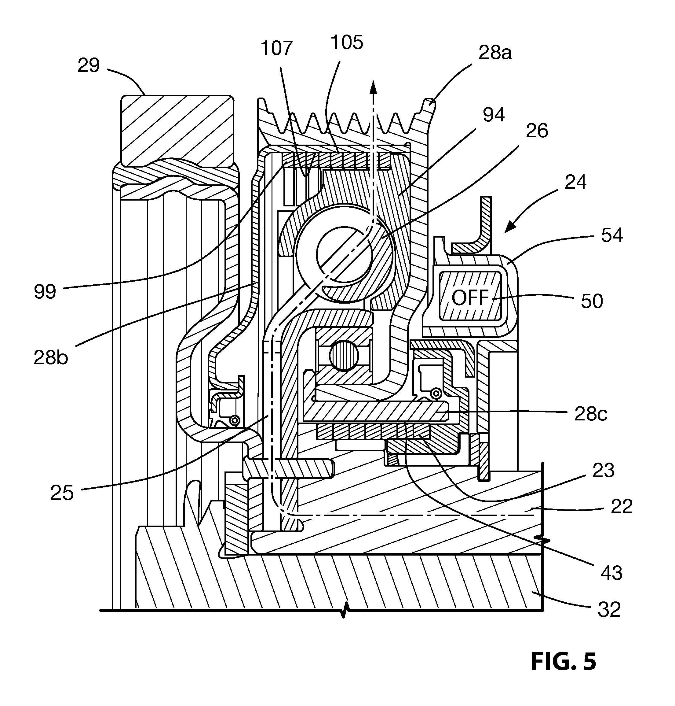
FIG. 5 is a magnified sectional elevation view of the clutched device shown in FIG. 2, showing a particular torque path through the clutched device; and
FIG. 6 is a magnified sectional elevation view of the clutched device shown in FIG. 2, showing another torque path through the clutched device.
DETAILED DESCRIPTION OF EMBODIMENTS
Reference is made to FIG. 1, which shows an engine 10 for a vehicle. The engine 10 includes a crankshaft 12 which drives an endless drive member 14, which may be referred to as a belt 14 for convenience, with the understanding that any other suitable endless drive member could instead be used. Via the belt 14, the engine 10 drives a plurality of accessories 16, such as an MGU (motor-generator unit) 18. Each accessory 16 includes an input drive shaft 15 with a pulley 13 thereon, which is driven by the belt 14. The term `pulley` is used here for convenience, however, it will be understood that any suitable torque transfer member may be used depending on what the endless drive member 14 is.
A clutched device 20 is shown on the engine crankshaft 12 and acts to control torque transfer between the crankshaft 12 and the belt 14. The clutched device 20 may be referred to as a decoupler 20, because it provides the capability to at least somewhat isolate the belt 14 from torsional vibrations in the crankshaft 12 and to provide overrunning capability at the belt 14, permitting the belt 14 to briefly overrun the crankshaft 12 as needed. The decoupler 12, in some embodiments, also provides the capability for the belt 14 to drive the crankshaft 12 so as to provide boost or BAS (belt/alternator start) capability to the engine 10.
The decoupler 20 is shown in an enlarged perspective view in FIG. 2, in a perspective exploded view in FIGS. 3a and 3b, and in a sectional elevation view in FIG. 4. As seen in FIGS. 2-4, the decoupler 20 includes a hub 22, a hub drive clutch 23 that may be referred to as a first one-way clutch, a clutch actuator assembly 24, first and second isolation springs 26 (shown individually at 26a and 26b), a decoupler pulley 28, and a pulley overrun clutch 99 that may be referred to as a second one-way clutch. Optionally, the decoupler 20 further includes a torsional vibration damper (TVD) 29.
The hub 22 may be adapted to mount to the crankshaft 12 (FIG. 1) in any suitable way. For example, the hub 22 may have an aperture 31 (FIG. 4) for a threaded fastener 32 that passes therethrough into a threaded aperture in the end of the crankshaft 12. The hub 22 defines a decoupler axis A (FIG. 4) and is rotatable about the decoupler axis A.
The hub 22 has a cup 33 fixedly connected to it. The cup 33 supports a bearing 36 that, in turn, supports the pulley 28 so as to permit relative rotation between the pulley 28 and the crankshaft 12 and hub 22. The bearing 36 may be any suitable type of bearing, such as a single row ball bearing. Alternatively any other suitable means of supporting the pulley 28 for rotation relative to the hub 22 may be used.
The isolation springs 26 elastically deform to isolate the endless drive member 14 and the crankshaft 12 from vibrations or other sudden changes in torque in one another. In the specific embodiment shown, the isolation springs 26 transfer force between the hub 22 and the pulley 28 via arms 25a on a driver 25 that is fixedly mounted to the hub 22 and axially overlapping internal lugs 95 on a spring shell 94, and via a spring shell 94. Such means for transferring torque from a hub into arcuate compression springs such as springs 26, and from arcuate compression springs into a spring shell are well known in the art.
The springs 26 in the examples shown are arcuate, helical coil compression springs made from any suitable material such as spring steel. However, any other suitable type of springs could be used, such as, for example, closed cell foam or PTU springs. The springs 26 operate in parallel. A single isolation spring 26 may be provided, or three or more springs 26 instead of the two springs 26 shown.
The spring shell shown at 94 which may be polymeric may be provided so as to prevent contact between the radially outer surface of the springs 26 and the inner surface of the pulley 28. Optionally, the isolation springs 26 may be preloaded so as to help keep all the components engaged at least when the clutched device 20 is in a home position.
The spring shell 94 may constitute an intermediate member between the hub 22 and the pulley 28, and is operatively connected to the pulley 28 via a pulley overrun clutch 99, which may be, as shown, a wrap spring clutch that has a first helical end 101 that engages a spring shell engagement surface 103 on the spring shell 94, and that has an outer surface 105 that engages a radially inner surface 107 of the pulley 28, which may be referred to as a pulley overrun clutch engagement surface 107.
The pulley 28 is supported for rotation relative to the crankshaft 12 via the bearing 36 and is engageable with the belt 14. The pulley 28, in the embodiment shown has a belt engagement surface 72 that is configured to engage a poly-V groove belt. The pulley 28 may be made from a plurality of elements including a main portion 28a, a cover member 28b that is connected to the main portion 28a via any suitable means, and a sleeve 28c. The pulley 28 may be made from any suitable material such as a suitable metal, such as steel.
The hub drive clutch 23 is controllable to transfer torque from the pulley 28 to the hub 22 (during rotation of the pulley 28 in a first rotational direction D1). The clutch 23 is also controllable to permit overrunning of the pulley 28 relative to the hub 22 in the first direction D1). The clutch 23 may be a one-way clutch and more specifically may be a wrap spring clutch, having a radially outer surface 38, a first helical end 39 and a second helical end 40 that is formed into a tang. The first helical end 39 of the wrap spring clutch 23 engages a first end engagement surface 42 on the shaft (FIG. 3B) for torque transfer therewith. The outer surface 38 is engageable with a radially inner surface of the pulley 28 that may be referred to as a clutch engagement surface 43 for torque transfer therewith.
The surface 43 may be referred to as a hub drive clutch engagement surface 43. The rest position of the wrap spring clutch 23 may be such that the outer surface 38 is substantially operatively disengaged from the clutch engagement surface 43. Thus, when the wrap spring clutch 23 is in the rest position during rotation of the pulley 28 relative to the hub 22, the wrap spring clutch 23 disengages the pulley 28 and the hub 22 from each other.
The clutch actuator assembly 24 includes an electromagnetic coil 50, an armature 52, an actuation body 53, an armature biasing spring 55, and a spring support 57. The electromagnetic coil 50 is mounted in a coil housing 54 that is itself mountable (e.g. via threaded fasteners 59) to a stationary surface 61 such as a portion of a mounting bracket for the engine 10. The coil 50 is connected to a control system 56 and to a power source 58. The power source 58 may be any suitable power source such as the vehicle battery.
The biasing spring 55 urges the armature 52 away from the pulley 68 to assist in separating the armature 52 from the pulley 28 when power to the coil 50 is cut. The spring support 57 is mounted to a stationary structure such as the aforementioned mounting bracket.
Energization of the coil 50 draws the armature 52 axially into engagement with a wall 68 of the pulley 28. The armature 52 is rotationally connected to the actuation member 53, which is, in turn rotationally connected to the second end 40 of the wrap spring clutch 23 (e.g. by means of a tang aperture 111 on the actuation member 53 that receives the tang at the second end 40 of the wrap spring clutch 23. Friction of the armature 52 against the pulley wall 68 drives the second end 40 of the wrap spring clutch 23 rotationally relative to the first end 39, in a direction which causes radial expansion of the wrap spring clutch 23 so as to engage the surface 43 on the pulley 28, thereby operatively connecting the pulley 28 to the hub 22. This is useful for when it is desired to `warm-start` the vehicle (when the vehicle's engine is to be started again after having been stopped momentarily at a stop light as a fuel saving measure). In such a situation the MGU 18 (FIG. 1) is operated as a motor and drives the belt 14, which, in turn, drives the pulley 28.
Deenergization of the coil 50 reduces or eliminates the friction between the armature 52 and the pulley wall 68. The armature 52 is assisted in separating from the wall 68 by the biasing member 55, as noted above. The clutch 23 may remain engaged however between the pulley 28 and the hub 22, until such time that the hub 22 overruns the pulley 28, at which point the wrap spring clutch 23 will return to its rest position and operatively disconnect the pulley 28 from the hub 22.
It will be noted that when the pulley 28 drives the hub 22, the torque transfer bypasses the isolation springs 26. This is because the pulley overrun clutch 99 will operate in an overrun condition when the pulley 28 rotates in the first rotational direction D1.
A suitable bushing is shown at 113, so as to facilitate relative rotational movement of the actuation member 53 with respect to the hub 22.
A slip ring 115 is provided so as to inhibit binding of the wrap spring clutch 23 during operation.
While the pulley overrun clutch has been shown to be a wrap spring clutch it may be any other suitable kind of one way clutch.
FIG. 5 shows the torque transfer path (from hub 22 to driver 25, to springs 26, to spring shell 94, to clutch 99 to pulley 28) during normal driving. FIG. 6 shows the torque path (from pulley 28 to clutch 23 to hub 22) during boosting of the engine by the MGU 18. Some torque will also be transferred through the armature 52 and actuation member 53 which is engaged with the tang at end 40 of the clutch 23. Torque transfer during a warm start (after stopping at a stoplight momentarily) will be similar to FIG. 6. Torque transfer during a `cold start` (using the engine's starter motor (not shown) may be similar to FIG. 5).
Those skilled in the art will understand that a variety of modifications may be effected to the embodiments described herein without departing from the scope of the appended claims.
* * * * *
D00000
D00001
D00002
D00003
D00004
D00005
D00006
D00007
XML
uspto.report is an independent third-party trademark research tool that is not affiliated, endorsed, or sponsored by the United States Patent and Trademark Office (USPTO) or any other governmental organization. The information provided by uspto.report is based on publicly available data at the time of writing and is intended for informational purposes only.
While we strive to provide accurate and up-to-date information, we do not guarantee the accuracy, completeness, reliability, or suitability of the information displayed on this site. The use of this site is at your own risk. Any reliance you place on such information is therefore strictly at your own risk.
All official trademark data, including owner information, should be verified by visiting the official USPTO website at www.uspto.gov. This site is not intended to replace professional legal advice and should not be used as a substitute for consulting with a legal professional who is knowledgeable about trademark law.