Apparatus for use in spinal interbody fusion
McLean , et al. A
U.S. patent number 10,376,387 [Application Number 16/031,526] was granted by the patent office on 2019-08-13 for apparatus for use in spinal interbody fusion. This patent grant is currently assigned to SPINE WAVE, INC. The grantee listed for this patent is SPINE WAVE, INC.. Invention is credited to Peter Barreiro, David Boisvert, Scott McLean, Fabio Amaral Pinto.


View All Diagrams
| United States Patent | 10,376,387 |
| McLean , et al. | August 13, 2019 |
Apparatus for use in spinal interbody fusion
Abstract
An expandable interbody fusion device includes superior and inferior endplates that are configured to receive a sequentially inserted stack of expansion members or wafers in interlocking engagement. The expansion members are formed to each have a generally U-shaped rearward facing opening. The superior and inferior endplates have openings through their outer surfaces in at least partial alignment and communication with the rearward facing openings of the expansion members. The inferior endplate has a fully bounded cavity for telescoping receipt of the superior endplate. The inferior endplate also has a fully bounded channel extending through the rear endwall thereof in direct communication with the rearward facing opening of at least one expansion member for the receipt of bone graft material into the device to promote fusion between opposing vertebral bodies of the spine.
| Inventors: | McLean; Scott (Sandy Hook, CT), Pinto; Fabio Amaral (Stamford, CT), Barreiro; Peter (West Haven, CT), Boisvert; David (Meriden, CT) | ||||||||||
|---|---|---|---|---|---|---|---|---|---|---|---|
| Applicant: |
|
||||||||||
| Assignee: | SPINE WAVE, INC (Shelton,
CT) |
||||||||||
| Family ID: | 51531311 | ||||||||||
| Appl. No.: | 16/031,526 | ||||||||||
| Filed: | July 10, 2018 |
Prior Publication Data
| Document Identifier | Publication Date | |
|---|---|---|
| US 20180318104 A1 | Nov 8, 2018 | |
Related U.S. Patent Documents
| Application Number | Filing Date | Patent Number | Issue Date | ||
|---|---|---|---|---|---|
| 15864267 | Jan 8, 2018 | 10022242 | |||
| 15373587 | Apr 24, 2018 | 9949844 | |||
| 14550258 | Dec 13, 2016 | 9517141 | |||
| 13795054 | Dec 2, 2014 | 8900312 | |||
| Current U.S. Class: | 1/1 |
| Current CPC Class: | A61F 2/4455 (20130101); A61F 2/442 (20130101); A61F 2/447 (20130101); A61F 2/4611 (20130101); A61F 2/4601 (20130101); A61F 2002/30774 (20130101); A61F 2002/30604 (20130101); A61F 2002/3093 (20130101); A61F 2002/30401 (20130101); A61F 2002/30131 (20130101); A61F 2002/30579 (20130101); A61F 2250/0009 (20130101); A61F 2002/30599 (20130101); A61F 2002/4627 (20130101); A61F 2/4603 (20130101); A61F 2002/30777 (20130101); A61F 2002/30828 (20130101); A61F 2002/30784 (20130101); A61F 2002/305 (20130101); A61F 2002/30601 (20130101); A61F 2002/30383 (20130101); A61F 2220/0008 (20130101); A61F 2002/30593 (20130101); A61F 2310/00005 (20130101) |
| Current International Class: | A61F 2/44 (20060101); A61F 2/46 (20060101); A61F 2/30 (20060101) |
| Field of Search: | ;623/17.11-17.16,21.11-21.19 ;606/99-100 |
References Cited [Referenced By]
U.S. Patent Documents
| 3486505 | December 1969 | Morrison |
| 4524766 | June 1985 | Petersen |
| 4683476 | July 1987 | Ferrari et al. |
| 4736738 | April 1988 | Lipovsek et al. |
| 4743493 | May 1988 | Sioshansi et al. |
| 4755797 | July 1988 | Kanaya |
| 4863476 | September 1989 | Shepperd |
| 4888024 | December 1989 | Powlan |
| 5059193 | October 1991 | Kuslich |
| 5192326 | March 1993 | Bao et al. |
| 5192327 | March 1993 | Brantigan |
| 5197971 | March 1993 | Bonutti |
| 5298254 | March 1994 | Prewett et al. |
| 5431658 | July 1995 | Moskovich |
| 5439684 | August 1995 | Prewett et al. |
| 5505732 | April 1996 | Michelson |
| 5514180 | May 1996 | Heggeness et al. |
| 5522899 | June 1996 | Michelson |
| 5571109 | November 1996 | Bertagnoli |
| 5591235 | January 1997 | Kuslich |
| 5645599 | July 1997 | Samani |
| 5702454 | December 1997 | Baumgartner |
| 5755797 | May 1998 | Baumgartner |
| 5756127 | May 1998 | Grisoni et al. |
| 5766252 | June 1998 | Henry et al. |
| 5836948 | November 1998 | Zucherman et al. |
| 5860977 | January 1999 | Zucherman et al. |
| 5891147 | April 1999 | Moskovitz et al. |
| 5951553 | September 1999 | Betz et al. |
| 5980522 | November 1999 | Koros et al. |
| 6033411 | March 2000 | Preissman |
| 6045579 | April 2000 | Hochshuler et al. |
| 6066154 | May 2000 | Reiley et al. |
| 6074390 | June 2000 | Zucherman et al. |
| 6110179 | August 2000 | Flivik et al. |
| 6110210 | August 2000 | Norton et al. |
| 6159211 | December 2000 | Boriani et al. |
| 6159244 | December 2000 | Suddaby |
| 6190414 | February 2001 | Young et al. |
| 6200347 | March 2001 | Anderson et al. |
| 6241771 | June 2001 | Gresser et al. |
| 6273916 | August 2001 | Murphy |
| 6279916 | August 2001 | Stecher |
| 6287308 | September 2001 | Betz et al. |
| 6287309 | September 2001 | Baccelli et al. |
| 6290724 | September 2001 | Marino |
| 6387130 | May 2002 | Stone et al. |
| 6395034 | May 2002 | Suddaby |
| 6402750 | June 2002 | Atkinson et al. |
| 6419705 | July 2002 | Erickson |
| 6432107 | August 2002 | Ferree |
| 6436142 | August 2002 | Paes et al. |
| 6478800 | November 2002 | Fraser et al. |
| 6488710 | December 2002 | Besselink |
| 6500205 | December 2002 | Michelson |
| 6520993 | February 2003 | James et al. |
| 6562074 | May 2003 | Gerbec et al. |
| 6595998 | July 2003 | Johnson et al. |
| 6620196 | September 2003 | Trieu |
| 6648917 | November 2003 | Gerbec et al. |
| 6656178 | December 2003 | Veldhuizen et al. |
| 6726691 | April 2004 | Osorio et al. |
| 6740093 | May 2004 | Hochschuler et al. |
| 6837904 | January 2005 | Ralph et al. |
| 6852095 | February 2005 | Ray |
| 6852126 | February 2005 | Ahlgren |
| 6852129 | February 2005 | Gerbec et al. |
| 6863673 | March 2005 | Gerbec et al. |
| 6997929 | February 2006 | Manzi et al. |
| 7094257 | August 2006 | Mujwid et al. |
| 7118580 | October 2006 | Beyersdorff et al. |
| 7591852 | September 2009 | Prosser |
| 7780732 | August 2010 | Abernathie |
| 7918891 | April 2011 | Curran et al. |
| 7931688 | April 2011 | Landry et al. |
| 7967867 | June 2011 | Barreiro et al. |
| 8062375 | November 2011 | Glerum et al. |
| 8303663 | November 2012 | Jimenez et al. |
| 8303879 | November 2012 | Bertele et al. |
| 8308805 | November 2012 | Lynn et al. |
| 8337562 | December 2012 | Landry et al. |
| 8382842 | February 2013 | Greenhalgh et al. |
| 8491658 | July 2013 | Etminan |
| 8628578 | January 2014 | Miller et al. |
| 8795369 | August 2014 | Pimenta et al. |
| 2002/0026195 | February 2002 | Layne et al. |
| 2002/0147497 | October 2002 | Belef et al. |
| 2002/0177897 | November 2002 | Michelson |
| 2002/0183761 | December 2002 | Johnson et al. |
| 2003/0074064 | April 2003 | Gerbec |
| 2003/0171812 | September 2003 | Grunberg et al. |
| 2004/0019354 | January 2004 | Johnson et al. |
| 2004/0054412 | March 2004 | Gerbec et al. |
| 2004/0064144 | April 2004 | Johnson et al. |
| 2004/0162618 | August 2004 | Mujwid et al. |
| 2004/0220580 | November 2004 | Johnson et al. |
| 2004/0230198 | November 2004 | Manzi et al. |
| 2005/0027364 | February 2005 | Kim et al. |
| 2005/0033429 | February 2005 | Kuo |
| 2005/0065517 | March 2005 | Chin |
| 2005/0149194 | July 2005 | Ahlgren |
| 2005/0283244 | December 2005 | Gordon et al. |
| 2006/0058807 | March 2006 | Landry et al. |
| 2006/0058880 | March 2006 | Wysocki et al. |
| 2006/0129244 | June 2006 | Ensign |
| 2008/0021558 | January 2008 | Thramann |
| 2008/0154377 | June 2008 | Voellmicke |
| 2008/0161927 | July 2008 | Savage et al. |
| 2008/0172127 | July 2008 | Perez-Cruet et al. |
| 2008/0300598 | December 2008 | Barreiro et al. |
| 2009/0138086 | May 2009 | Dewey |
| 2009/0198339 | August 2009 | Kleiner et al. |
| 2010/0179594 | July 2010 | Theofilos et al. |
| 2010/0179656 | July 2010 | Theofilos |
| 2010/0292796 | November 2010 | Greenhalgh et al. |
| 2010/0312347 | December 2010 | Arramon et al. |
| 2012/0022653 | January 2012 | Kirschman |
| 2012/0123548 | May 2012 | Lynn |
| 2012/0158144 | June 2012 | Ullrich, Jr. et al. |
| 2012/0191190 | July 2012 | Trieu |
| 2012/0197405 | August 2012 | Cuevas et al. |
| 2012/0226357 | September 2012 | Varela |
| 2012/0253406 | October 2012 | Bae et al. |
| 2013/0090735 | April 2013 | Mermuys et al. |
| 2013/0190875 | July 2013 | Shulock |
| 2014/0148903 | May 2014 | Pinto |
| 0621020 | Oct 1994 | EP | |||
| 2639823 | Jun 1990 | FR | |||
| 2719763 | Nov 1995 | FR | |||
| 2004525692 | Aug 2004 | JP | |||
| 2006517836 | Aug 2006 | JP | |||
| 2011513001 | Apr 2011 | JP | |||
| 9902214 | Jan 1999 | WO | |||
| 02/071921 | Sep 2002 | WO | |||
| 2009/114381 | Sep 2009 | WO | |||
Other References
|
PCT Search Report for corresponding PCT Application No. PCT/US2008/064534, dated Sep. 12, 2008. cited by applicant . Baddeley, S. and Cullen, J.C., "The Use of Methylmethacrylate in the Treatment of Giant Cell Tumours of the Proximal Tibia", Aust. N.Z. J. Surg. vol. 49--No. 1, Feb. 1979, 3 pp. cited by applicant . Campanacci, M., Gui, L., Ranieri, L., Savini, R., "Treatment of Tibial Plateau Fractures", Chi. Org. Mov. 72(3), Dec. 1975 (Italian text) pp. 234-256, English Translation 15 pp. cited by applicant . Kyphon Inc., Surgical Technique Manual Nov. 16, 1999, pp. 5, 6, 9, 16-19. cited by applicant . Kyphon web page, www.kyphon.com, Mar. 13, 2001, 1 p. cited by applicant . Signus Medical, TETRIS, Sep. 2003, 1 p. cited by applicant . Blackstone Medical Inc., Construx.TM. PEEK VBR System, 2005, www.blackstonemedical.com, 1 p. cited by applicant. |
Primary Examiner: Lawson; Matthew J
Attorney, Agent or Firm: Hoffmann & Baron, LLP
Parent Case Text
CROSS-REFERENCE TO RELATED APPLICATION
This application is a continuation application of U.S. application Ser. No. 15/864,267, filed Jan. 8, 2018, now U.S. Pat. No. 10,022,242, which is a continuation application of U.S. application Ser. No. 15/373,587, filed Dec. 9, 2016, now U.S. Pat. No. 9,949,844, which is a continuation application of U.S. application Ser. No. 14/550,258, filed Nov. 21, 2014, now U.S. Pat. No. 9,517,141, which is a divisional application of U.S. application Ser. No. 13/795,054, filed Mar. 12, 2013, now U.S. Pat. No. 8,900,312, the entire contents of which are incorporated by reference herein.
Claims
The invention claimed is:
1. An apparatus for use in spinal interbody fusion, comprising: an expandable device including a first outer surface for contacting one vertebral body in a spine and a second outer surface for contacting a second opposing vertebral body in said spine, a front end, a rear end, and a channel extending into said expandable device; an inserter including a track assembly having a distal end and a proximal end, said inserter being releasably attached to said expandable device; an insert supported by said track assembly for insertion into said expandable device through said channel, said insert including an angled lifting surface configured and oriented to cause expansion of said expandable device during insertion of said insert; and a guide pin releasably connected to said expandable device and detachably connected to said track assembly, said guide pin being supported by said track assembly and being detachable therefrom, said guide pin remaining releasably connected to said expandable device upon detachment of said inserter from said expandable device and said guide pin, said guide pin being configured to serve as a locator for subsequent attachment to another apparatus, including an apparatus for introducing bone graft material into said expandable device through said channel.
2. The apparatus of claim 1, wherein said expandable device comprises a first opening through said first outer surface and a second opening through said second outer surface, said channel communicating with said first opening and said second opening.
3. The apparatus of claim 2, wherein said expandable device comprises a first endplate defining said first outer surface and said first opening therethrough, and a second endplate defining said second outer surface and said second opening therethrough, said first endplate and said second endplate being movable relative to each other in an expansion direction.
4. The apparatus of claim 3, wherein said insert has an insert opening extending through said rear end of said insert and facing rearwardly, said insert opening being in communication with said channel and with said opening of said first endplate and said opening of said second endplate.
5. The apparatus of claim 4, wherein said insert further includes a locking structure to lock said insert in said expandable device upon expansion.
6. The apparatus of claim 1, wherein said guide pin extends within said track assembly.
7. The apparatus of claim 1, wherein said rear end of said expandable device includes an attachment surface for releasable attachment of said inserter.
8. The apparatus of claim 7, wherein said attachment surface includes at least one notch adjacent the rear end of said expandable device.
9. The apparatus of claim 8, wherein said distal end of said track assembly comprises at least one finger projecting outwardly from said distal end for engagement with said at least one notch.
10. The apparatus of claim 1, wherein said guide pin is elongate having a distal end and a proximal end, said guide pin being releasably connected at said distal end to said expandable device by a threaded connection.
11. The apparatus of claim 1, wherein said inserter includes a disconnect member at the proximal end of said track assembly for allowing said track assembly to be detached from said guide pin while said guide pin remains releasably connected to said expandable device.
12. The apparatus of claim 1, wherein said track assembly further comprises a driver having a distal end and a proximal end, the distal end being configured to engage said insert and drive said insert into said expandable device through said channel.
13. The apparatus of claim 1, wherein said expandable device comprises; a) an elongate superior endplate having said first outer surface for contacting one vertebral body in a spine, and an opposite lower surface including a downwardly-facing engagement surface thereon; b) an elongate inferior endplate aligned in the axial direction with said superior endplate and having said second outer surface for contacting an opposing vertebral body in said spine, said superior endplate and said inferior endplate being movable relatively away from each other in an expansion direction generally transverse to said axial direction; and c) wherein said insert has a leading front end and a trailing rear end and is configured and sized for insertion between said superior endplate and said inferior endplate, said angled lifting surface being configured and disposed to engage said downwardly- facing engagement surface of said superior endplate for causing expansion of said expandable device during insertion of said insert.
14. The apparatus of claim 13, wherein said insert comprises a locking surface for locking engagement with said device to resist retrograde movement of said insert upon expansion of said expandable device.
15. The apparatus of claim 13, wherein said expandable device has an opening configured for receipt of said bone graft material.
16. The apparatus of claim 15, wherein said opening for receipt of said bone graft material is defined by said channel.
17. The apparatus of claim 15, further comprising bone graft material received into said expandable device through said opening.
18. The apparatus of claim 1, wherein said guide pin is releasably connected at said rear end of said expandable device by a threaded connection.
Description
FIELD OF THE INVENTION
The subject invention relates generally to the field of spinal implants and more particularly to expandable interbody fusion devices with graft chambers.
BACKGROUND OF THE INVENTION
Spinal implants such as interbody fusion devices are used to treat degenerative disc disease and other damages or defects in the spinal disc between adjacent vertebrae. The disc may be herniated or suffering from a variety of degenerative conditions, such that the anatomical function of the spinal disc is disrupted. Most prevalent surgical treatment for these conditions is to fuse the two vertebrae surrounding the affected disc. In most cases, the entire disc will be removed, except for a portion of the annulus, by way of a discectomy procedure. A spinal fusion device is then introduced into the intradiscal space and suitable bone graft or bone substitute material is placed substantially in and/or adjacent the device in order to promote fusion between two adjacent vertebrae.
Certain spinal devices for achieving fusion are also expandable so as to correct disc height between the adjacent vertebrae. Examples of expandable interbody fusion devices are described in U.S. Pat. No. 6,595,998 entitled "Tissue Distraction Device", which issued on Jul. 22, 2003 (the '998 Patent), U.S. Pat. No. 7,931,688 entitled "Expandable Interbody Fusion Device", which issued on Apr. 26, 2011 (the '688 Patent), and U.S. Pat. No. 7,967,867 entitled "Expandable Interbody Fusion Device", which issued on Jun. 28, 2011 (the '867 Patent). The '998 Patent, the '688 Patent and the '867 Patent each discloses sequentially introducing in situ a series of elongate inserts referred to as wafers in a percutaneous approach to incrementally distract opposing vertebral bodies to stabilize the spine and correct spinal height, the wafers including features that allow adjacent wafers to interlock in multiple degrees of freedom. The '998 Patent, the '688 Patent and the '867 Patent are assigned to the same assignee as the present invention, the disclosures of these patents being incorporated herein by reference in their entirety.
Certain interbody fusion devices also include hollow portions or chambers that are filled with suitable material such as bone graft to promote fusion between vertebral bodies. The extent and size of the chambers establish areas of contact that are configured so as to assure maximum contact between the bone graft and the vertebral bodies. Sufficient surface area of the device surrounding the chambers needs to be maintained in order to provide an appropriate load bearing surface to withstand the compressive forces exerted by the opposing vertebral bodies. In addition, where expandable interbody fusion devices are used to correct height within the intradiscal space, the effect of shear forces on the expanded device due to torsional movement of the spine also needs to be considered.
Accordingly, there is a need to develop expandable interbody fusion devices with bone graft chambers that take into account and balance these factors, as well as to facilitate the introduction of bone graft into the device and through the graft chambers once expanded.
SUMMARY OF THE INVENTION
It is an object of the invention to provide an improved expandable device with openings serving as bone graft chambers for implantation into the intradiscal space between two opposing vertebral bodies of a spine having the facility for introducing bone graft thereinto upon expansion.
DESCRIPTION OF THE FIGURES
FIG. 1 is front perspective view of an expandable interbody fusion device in unexpanded condition in accordance with one embodiment of the present invention.
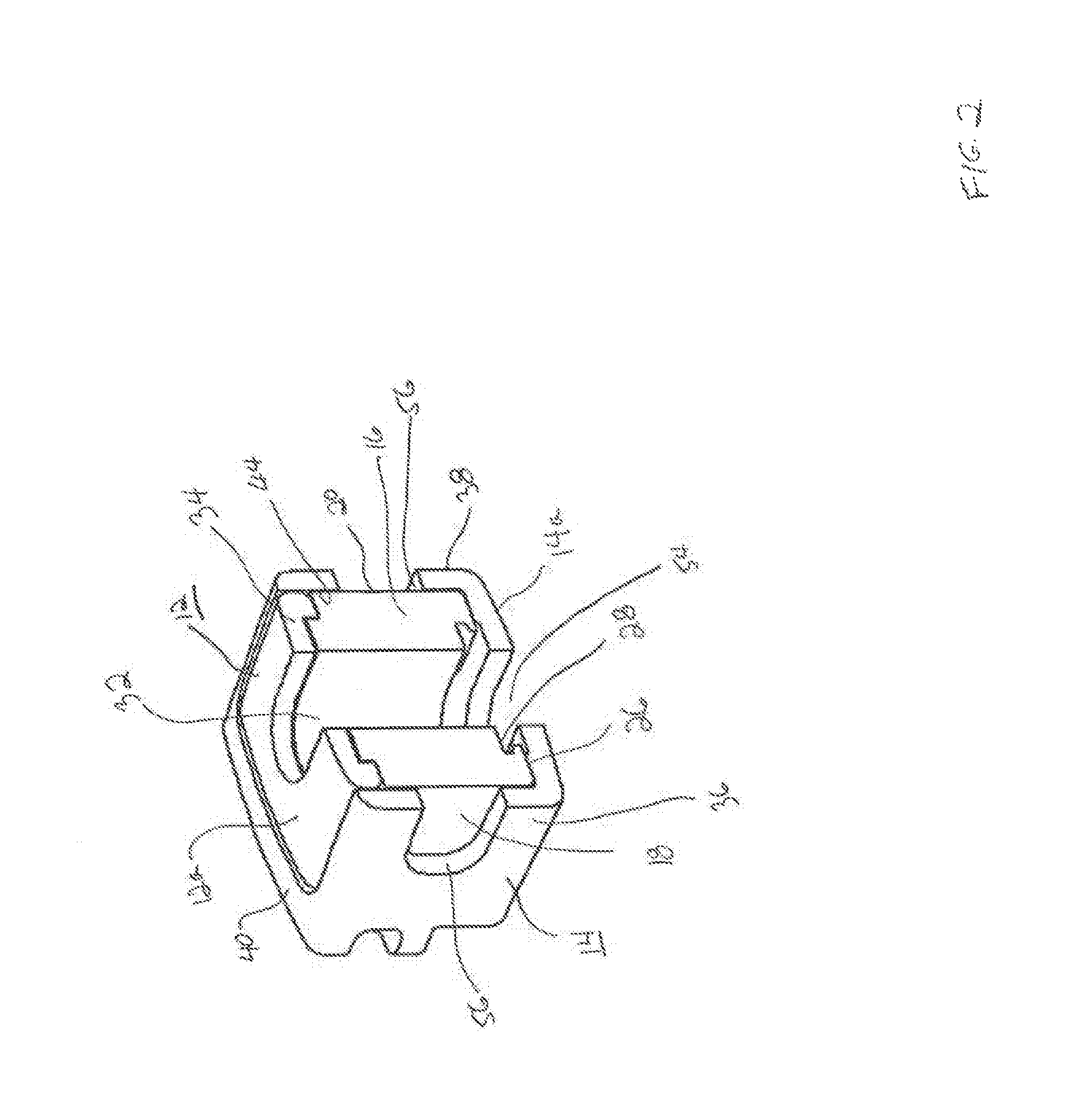
FIG. 2 is a perspective cross sectional view of the unexpanded device of FIG. 1 as seen along viewing lines II-II of FIG. 1.
FIG. 3 is a rear perspective view of the device of FIG. 1.
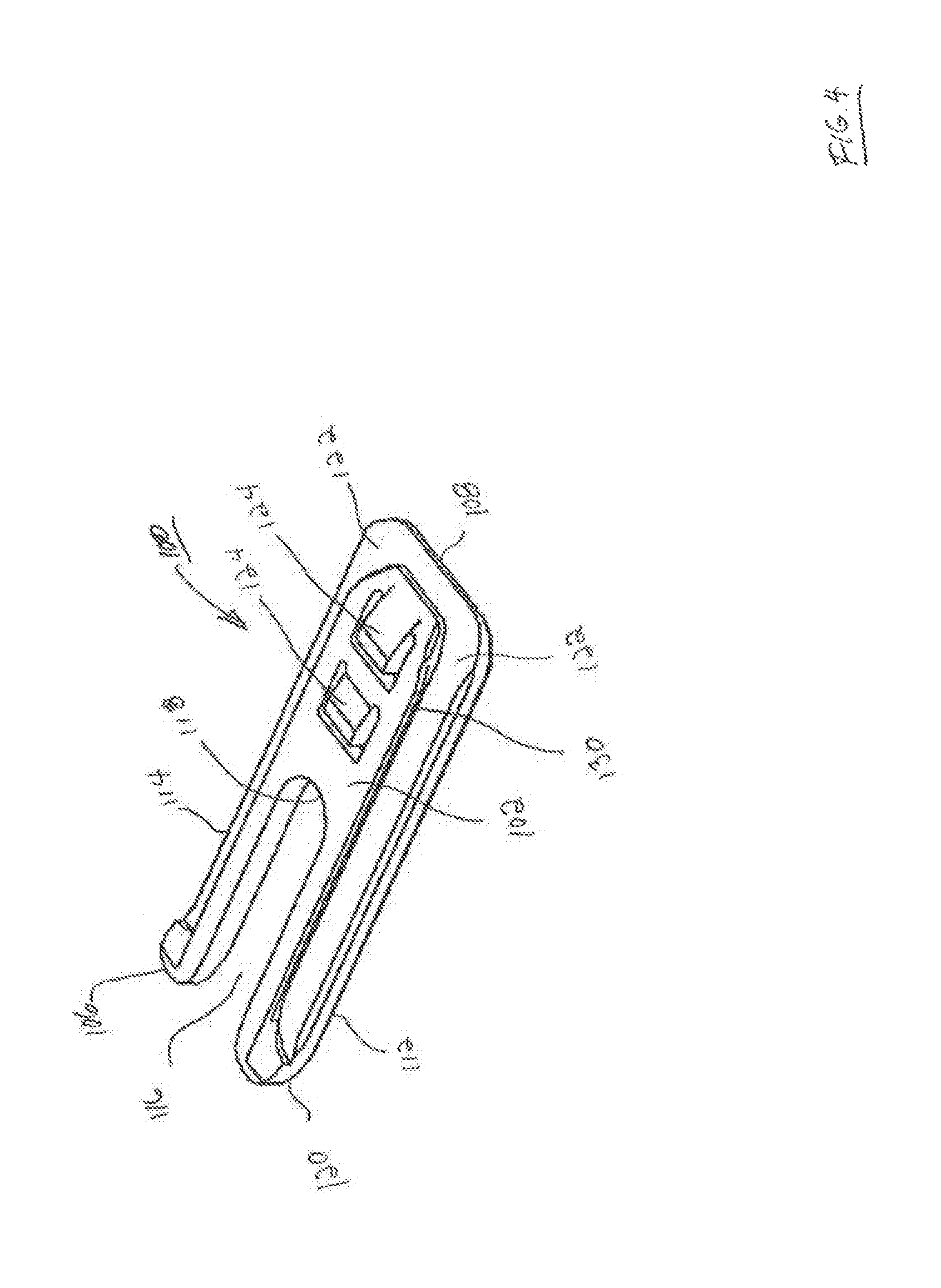
FIG. 4 is a top perspective view of an interlocking wafer serving as an expansion member to expand the interbody fusion device of FIG. 1.
FIG. 5 is a bottom perspective view of the interlocking wafer shown in FIG. 4.
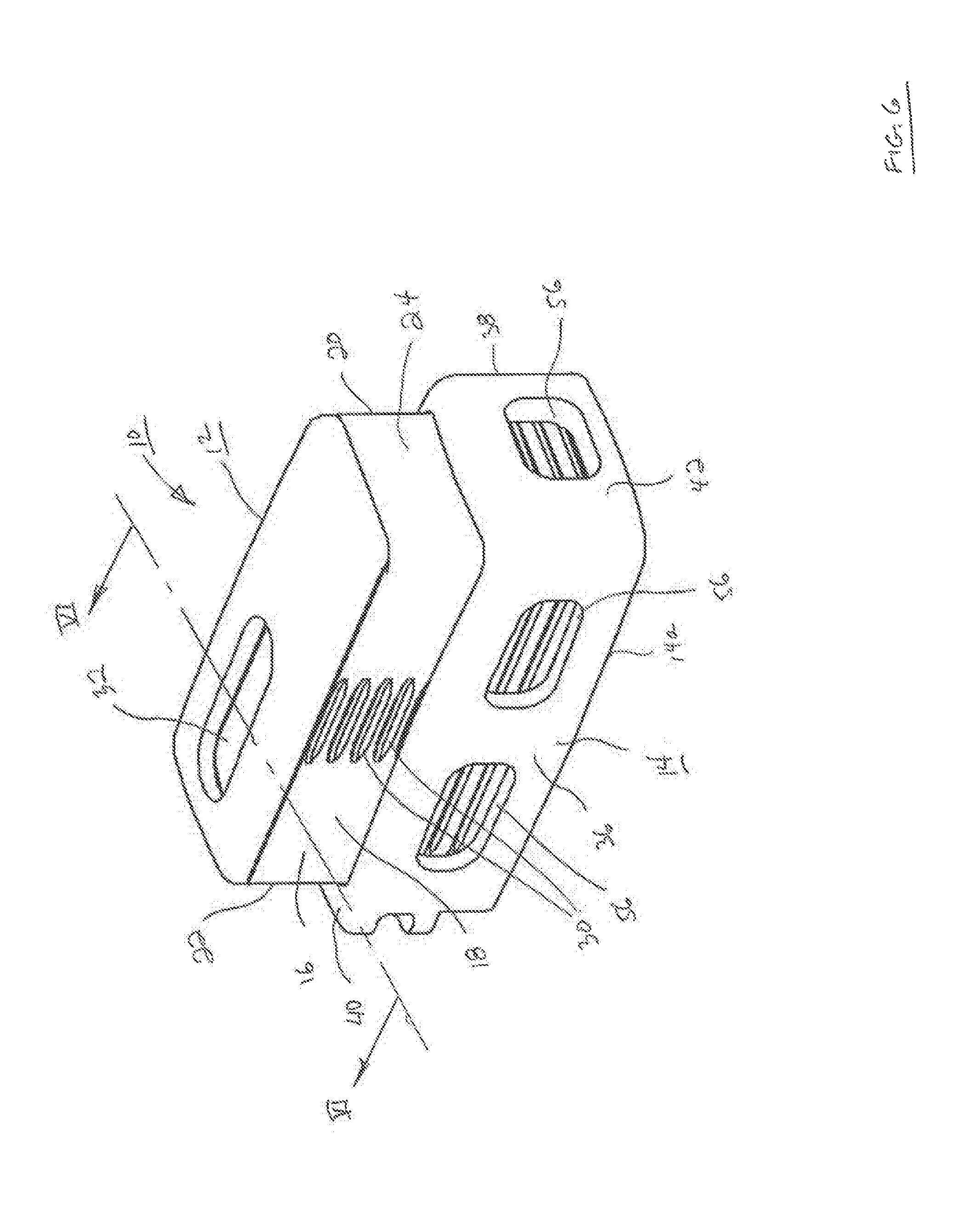
FIG. 6 is front perspective view of the expandable interbody fusion device FIG. 1 expanded to an expanded condition.
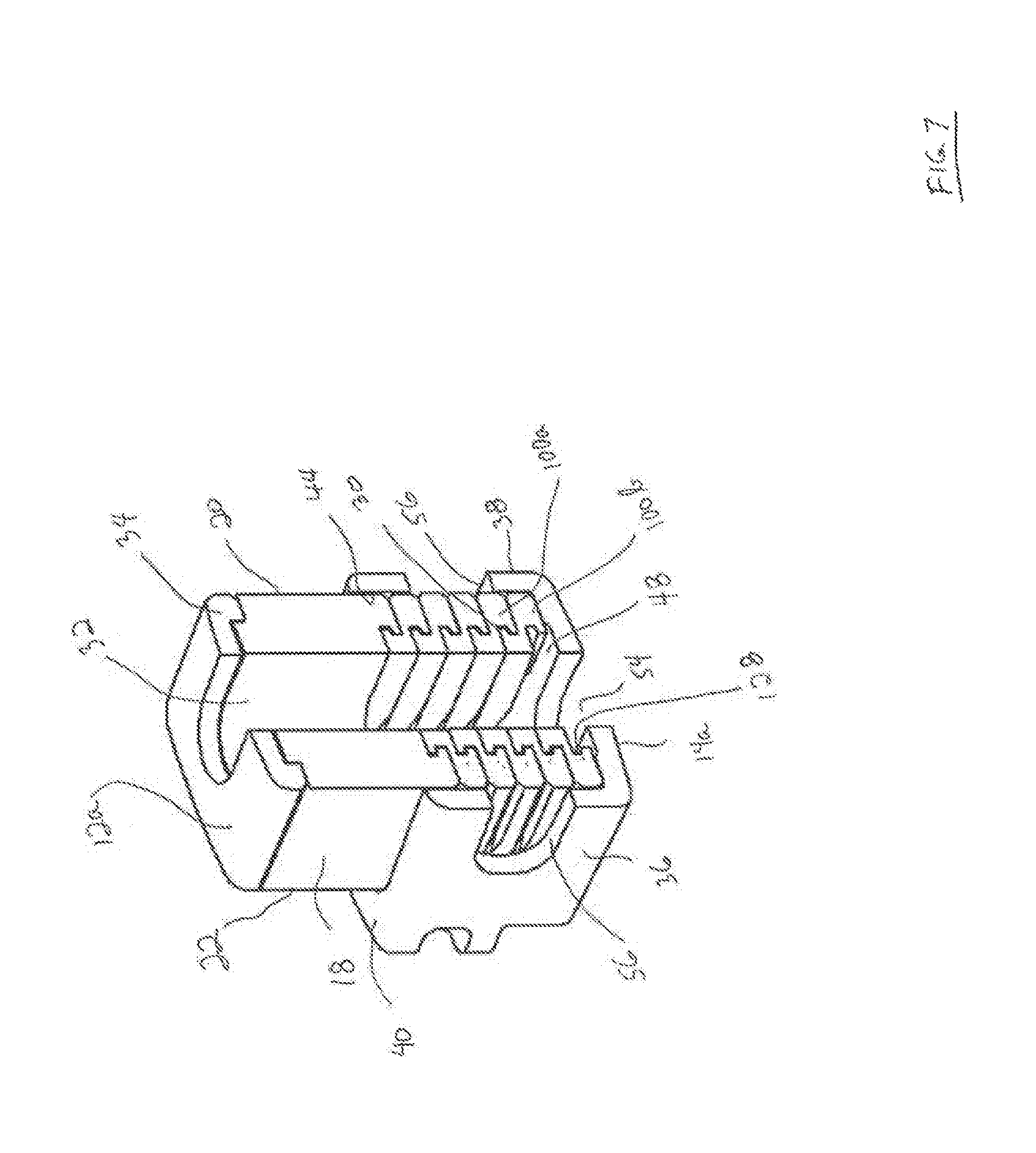
FIG. 7 is a perspective cross sectional view of the expanded device of FIG. 6 is seen along viewing lines VI-VI of FIG. 6.
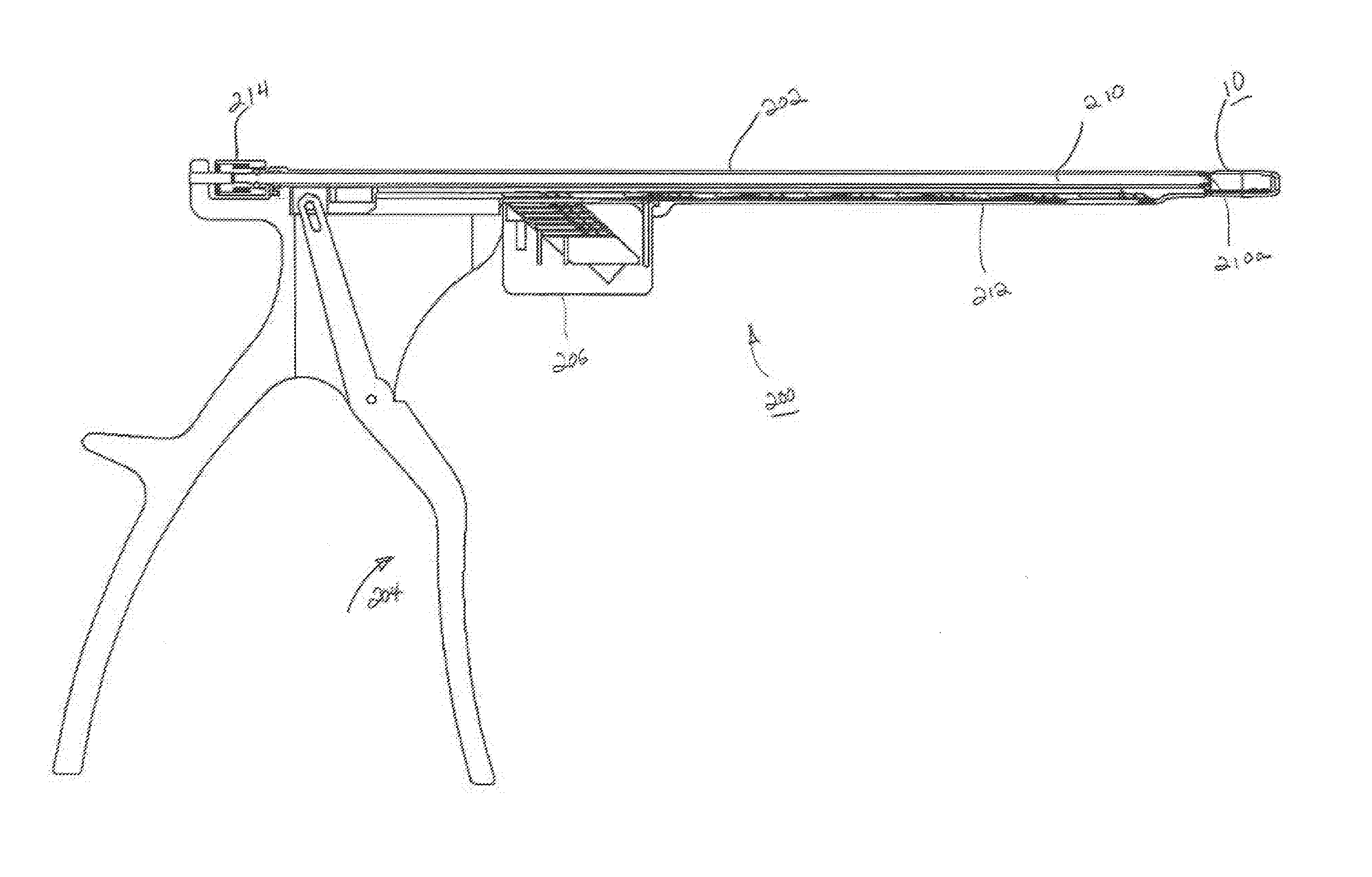
FIG. 8 is a top perspective view of an inserter for inserting wafers releasably connected to the unexpanded device of FIG. 1.
FIG. 9 is longitudinal cross sectional view of the inserter of FIG. 8.
FIG. 10 is a perspective view of the guide used with the inserter of FIG. 8 releasably connected to the expanded device of FIG. 6.
FIG. 11 is a top perspective view of an alternative lordotic expandable fusion device.
DESCRIPTION OF THE EMBODIMENTS
For the purposes of promoting and understanding of the principles of the invention, reference will now be made to the embodiments illustrated in the drawings and described in the following written specification. It is understood that no limitation to the scope of the invention is thereby intended. It is further understood that the present invention includes any alterations and modifications to the illustrated embodiments and includes further applications of the principles of the invention as would normally occur to one skilled in the art to which this invention pertains.
In accordance with one embodiment of the invention, an expandable interbody fusion device 10 includes a first superior endplate 12 and a second inferior endplate 14, as shown in FIGS. 1-3. The interbody fusion device 10 has a height across the superior and inferior endplates 12, 14 in the unexpanded condition as illustrated in FIGS. 1-3 that is less than the normal anatomic height of a typical intradiscal space. The invention contemplates that a series of expansion members, such as interlocking wafers 100 as will be described, are introduced into the device 10 to distract the opposing vertebrae by separating the superior and inferior endplates 12, 14 in situ. Insertion of the wafers 100 separates the endplates 12, 14 to expand the height of the device within the intradiscal space and to ultimately restore the normal anatomic height of the disc space. Expansion devices of this type are shown and described in the '998 Patent, the '688 Patent and the '867 Patent described hereinabove and incorporated herein by reference.
The present invention contemplates an improved interbody fusion device 10 that particularly includes openings that define graft chambers for containment of materials that promote bone fusion through the device between opposing vertebral bodies.
The superior endplate 12 as shown in FIGS. 1-3 and 6-7 is elongate and comprises a hub 16 having pair of side surfaces 18 and 20 extending longitudinally on each side of the hub 16 and a pair of end surfaces 22 and 24 extending respectively at the proximal rear end and the distal front end of the superior endplate 12. The hub 16 is sized and configured to fit within a cavity of the inferior endplate 14 for telescoping movement therewithin, as will be described. The lower surface 26 of the hub 16 (FIG. 2) includes a shaped configuration defined by wafer mating features 28 that are substantially identical to the mating features on the lower surface of each wafer 100, as will be described. The hub 16 defines a series of grooves 30 as shown in FIG. 6 extending along each side surface 18 and 20 thereof that is configured to engage ribs (not shown) projecting interiorly of the inferior endplate 14. This engagement temporarily holds the superior and inferior endplates together in the expansion direction as the device 10 is introduced into the intradiscal space to be distracted.
As shown particularly in FIGS. 1-3 and 6-7, the superior endplate 12 includes a graft chamber defined by an opening 32 extending through the upper outer surface 12a and the lower surface 26. In a particular arrangement, the opening 32 is situated to lie more adjacent to the proximal surface 20 or rear end of the device 10. In accordance with one arrangement, the superior endplate 12 is formed of a biocompatible polymer such as polyethylethylketone (PEEK). PEEK is used in fusion applications for its combination of strength, biocompatibility, and elasticity which is similar to human bone. Other composites may include derivatives of PEEK such as carbon fiber reinforced PEEK and PEKK, respectively. In a particular aspect, the superior endplate 12 may further include an upper endcap 34 that defines the outer surface 12a. Endcap 34 may be a separate plate formed of material for the promotion of bone growth, such as titanium, and may be attached to the endplate 12 with suitable conventional techniques. As an alternative, the upper surface 12a may be defined by a coating of a suitable layer of bone growth promotion material, such as titanium, which may be deposited by conventional techniques such as, for example, by ion implantation as described in U.S. Pat. No. 4,743,493, entitled "Ion Implantation of Plastics", issued on May 10, 1988 to Sioshansi et al., the contents of which are incorporated by reference herein.
The inferior endplate 14 of the interbody fusion device 10 as shown in FIGS. 1-3 and 6-7 is elongate and comprises a pair of opposing spaced apart sidewalls 36 and 38 extending along the longitudinal direction and projecting upwardly from the lower outer surface 14a. A pair of spaced apart endwalls 40 and 42 extend laterally across the device and project upwardly from outer surface 14a. Rear end wall 40 is disposed at the rear or proximal end of the device 10 and front end wall 42 is disposed at the front or distal end of the device 10. The side walls 36, 38 together with rear end wall 40 and front end wall 42 form an open, upwardly facing fully bounded interior cavity 44 as shown in FIGS. 1-2 and 7. The interior cavity 44 is sized and configured to receive the superior endplate 12 including the hub 16 and the endcap 34 in relatively close fit between the side walls 36 and 38 and the end walls 40 and 42 of the inferior endplate 14 in a non-expanded condition as shown in FIGS. 1 and 2. The hub 16 of superior endplate 12 remains fully contained within the inferior endplate 14 during telescoping expansion of the device 10 as shown in FIGS. 6 and 7, contributing to the torsional strength of the expanded device 10.
The inferior plate 14 as shown in FIG. 3 defines a fully bounded wafer channel 46 extending through the rear endwall 40 in communication with interior cavity 44 and through which the wafers 100 which serve as expansion members are introduced. The inferior endplate 14 includes a pair of opposite ledges 48 that define an upper support surface on which each wafer 100 is supported as it introduced into the wafer channel 46, as will be described. The ledges 48 define the bottom surface of the cavity 44. Wafers are introduced sequentially into wafer channel 46, as will be described. The rear endwall 40 further defines a threaded connection opening 50 for threaded releasable receipt of a guide pin for use in the introduction of wafers 100 and in the delivery of bone graft material into the device 10, as will also be described. Rear endwall 40 may also additionally include a pair of bilateral notches 52 adjacent the sidewalls 36 and 38 for use in attachment to portions of the wafer inserter for the establishment of a rigid connection to the device 10 for insertion into the intradiscal space.
As shown particularly in FIGS. 1-3 and 6-7, the inferior endplate 14 includes a graft chamber defined by an opening 54 extending through the lower outer surface 14a and the upper support surface 48 in communication with cavity 44. In a particular arrangement, the opening 54 is situated to lie more adjacent to the proximal surface 20 or rear end of the device 10 and at least in partial alignment with the opening 32 in superior endplate 12. In accordance with one arrangement, the inferior endplate 12 is formed of a material different from the material of the superior endplate 12. In this aspect, the inferior endplate 12 may be formed of a biocompatible metal, such as titanium, for its strength properties. Titanium is chosen for strength, biocompatibility, processing capability, and fluoroscopic imaging properties (radiolucency). Other alternative materials include cobalt chrome, stainless steel (both stronger than titanium but much less radiolucent), or biocompatible ceramics such as silicon nitride or zirconia, which are radiolucent. Titanium and silicon nitride have demonstrated good apposition to bone and superior to PEEK. In this regard where inferior endplate 14 is formed of titanium, the lower outer surface 14a would provide for the promotion of bone growth. Where inferior endplate 14 is not formed of a bone growth promotion material, lower outer surface 14a may be coated with a suitable layer of bone growth promotion material, such as titanium, and deposited in a conventional manner as described hereinabove.
Where inferior endplate 14 is formed of titanium or other suitable metal that is radiopaque, windows 56 may be formed through sidewalls 36 and 38 and/or through front endwall 42 as shown in FIGS. 1-3 and 6-7 so as to allow visual observation of the expansion of the device 10 upon insertion of the wafers 100 by suitable imaging techniques, such as fluoroscopy.
Details of an interlocking wafer 100 are shown in FIGS. 4-5. The wafer 100 is elongate and has an upper surface 102 and a lower surface 104, both of which are generally planar so that the wafers can form a stable stack within the interbody fusion device 10. Wafer 100 includes a trailing rear end 106 and a leading front end 108. The rear end 106 is formed substantially in the form of a horseshoe, with a pair of spaced opposing arms 112 and 114 defining an open rearward facing generally U-shaped opening 116. The surface 118 between the upper surface 102 and the lower surface 104 at the base of opening 116 defines a pushing surface, as will be described. The opening 116 at the rear end of each wafer 100 is provided to allow bone graft material to flow into the device 10 through the openings 116 and into the openings 32 and 54 extending through the superior endplate 12 and the inferior endplate 14, respectively.
The rear end 106 includes a downward-facing sloped surface 120 at the free end of each arm 112 and 114 that corresponds angularly to an upward-facing surface 122 on the leading front end 108 of the wafer 100. The sloped surfaces help displace an earlier inserted wafer 100 upon introduction of a new wafer. More specifically, when a first wafer 100a is introduced through the wafer channel 46, resting on the ledges 48, the downward-facing sloped surface 120 thereof is lifted upon contact with the upward-facing slope 122 of a newly inserted wafer 100b (FIG. 7). This allows the newly inserted wafer to ride along the ledges 48 until it is positioned fully underneath the previous wafer as more fully described in the '867 Patent.
The wafer 100 includes several features for interlocking engagement to the hub 16 and to adjacent wafers 100 in a complementary interlocking mating interface. One particular feature includes a series of locking elements defined by resiliently deflectable prongs 124 that project outwardly above the upper surface 102 of the wafer 100 in the direction of expansion of device 10. A complementary series of locking surfaces 126 are defined in the lower surface 104 of the wafer 100 for resilient engagement with the prongs 124 as wafers are inserted into device 10 to form a stack. It should be appreciated that the prongs 124 and associated locking surfaces 126 may be formed on either the upper surface or the lower surface of a wafer 100 as desired. The lower surface 104 of each wafer 100 as shown in FIGS. 5 and 7 also defines a T-slot configuration 128 for mating with a T-bar configuration 130 on the upper surface 102 of a successive wafer 100 as shown in FIGS. 4 and 7. It should be appreciated that the respective T-bar and T-slot configurations may also be formed on either the upper surface or the lower surface of a wafer 100 as desired. In the illustrated arrangement, there are two prongs 124 extending generally linearly and substantially centrally along the elongate longitudinal direction adjacent the front end 108 of wafer 100. The structure and function of a wafer 100 and the prongs 124 are more fully described in the '867 Patent, incorporated herein by reference.
The superior and inferior endplates 12 and 14 are configured to be initially releasably engaged by the ribs (not shown) and the grooves 30 when the device 10 is unexpanded, as shown in FIGS. 1 and 2. In this unexpanded condition, the device 10 is attached to an inserter 200 as shown in FIGS. 8 and 9. In this stage, the hub 16 is disposed within the cavity 44 of inferior endplate 14 with the ribs (not shown) on the interior surfaces of side walls 36, 38 engaging the grooves 30 extending along each side of the hub 16. The lower surface 26 of hub 16 is on or closely adjacent to the wafer support ledges 48 in facing relationship. This engagement temporarily holds the superior and inferior endplates together as the device 10 is introduced into the intradiscal space to be distracted. In this unexpanded condition the outer surface 12a of the superior endplate 12 is substantially flush with the upper surfaces of the sidewalls 36 and 38 as illustrated in FIGS. 1 and 2. In addition to providing strength for the device 10 as described hereinabove, such nesting of the superior endplate 12 within inferior endplate 14 allows for lower height of the unexpanded device 10.
The inserter 200 as illustrated in FIGS. 8 and 9 comprises a track assembly 202 and a handle 204 for individually sequentially inserting a plurality of wafers 100 supported linearly within the track assembly 202. A source of wafers 100 is provided in a cartridge 206 supported by the track assembly 202. A pair of opposing fingers 208 is provided at the distal end of the track assembly 202, fingers 208 releasably engaging the notches 52 in the rear endwall 40 for connection thereto. As depicted particularly in FIG. 9, the track assembly 202 supports an elongate guide pin 210 the distal end 210a of which is threaded for releasable threaded connection with threaded opening 50 in rear endwall 40 of the device 10. Inserter 200 comprises an elongate driver 212 that is translatably supported within the track assembly 202, the distal end of which is configured to enter the rearward facing opening 116 of each wafer 100 and engage the pushing surface 118. Upon actuation of the handle and translation of the driver 212, the wafer 100 is suitably moved through the channel 46 and into the device 10 by the force of the distal end of the driver 212 against the pushing surface 118. Inserter 200 further includes a quick disconnect member 214 which upon rotation allows the inserter 200 to be detached from the guide pin 210, thereby leaving the guide pin 210 releasably connected to the expanded device 10 after suitable insertion of the desired number of wafers, as shown in FIG. 10. With the guide pin 210 attached to the device 10 at opening 50, the channel 46 extending through the rear end wall 40 of device 10 is fully exposed and may be used for the introduction of suitable bone graft material into expanded device 10. For the introduction of a bone graft material, the guide pin 210 may be used as a locator for subsequent attachment to an apparatus containing such bone graft material whereby such apparatus may be supported by the guide pin 210 while allowing access into channel 46. Further details of the structure and operation of the inserter 200 are described in commonly assigned U.S. Pat. No. 6,997,929, entitled "Tissue Distraction Device", and issued Feb. 14, 2006, the contents of which are incorporated by reference herein.
The manner in which the interbody fusion device 10 is expanded is illustrated in FIGS. 6-7. When the first wafer 100 is introduced, the interlocking features on the upper surface 102 of the wafer 100 engage the mating features 28 on the lower surface 26 of superior endplate 12 lifting the superior endplate 12 upwardly within the cavity 44 between sidewalls 36, 38 and breaking the initial releasable engagement. When the first inserted wafer 100 is introduced into the device 10 the rearward facing opening 116 in the wafer 100 is located to be in at least partial alignment and communication with the openings 32 and 54 extending through the superior endplate 12 and inferior endplate 14, respectively. This process continues with each successive wafer 100 inserted beneath a previously inserted wafer 100 until a complete stack is formed telescopically lifting the superior endplate 12 relative to the inferior endplate 14, as depicted in FIG. 7. As each subsequent wafer 100 is introduced, the prongs 124 lockingly engage the mating locking surfaces 126 features on the lower surfaces of each previously introduced wafer 100, with the openings 116 of each wafer 100 being disposed such that they are in at least partial alignment and communication with the openings 116 of each previously introduced wafer 100. The lowermost wafer 100 is supported on the support surfaces of ledges 48 with the rearward facing opening being in direct communication with the channel 46 extending through rear endwall 40 of inferior endplate 14. It should be noted that all the wafers 100 are contained within and constricted by the opposing side walls 36, 38 and the rear and front end walls 40, 42 so as to provide additional resistance against torsional movement of the spine. The inserter 200 is released from the expanded interbody fusion device 10 upon unthreading the guide pin 210 from opening 50.
Having described the interbody fusion device 10, a suitable bone filler or bone graft to promote fusion between opposing vertebral bodies may be inserted into the expanded device 10 as well as into the intradiscal space adjacent to device 10. With the inserter 200 used to insert inserts such as wafers 100 into device 10 having been removed from the expanded device 10, it can be appreciated that the wafer insertion channel 46 provides clear and unobstructed access into the expanded device 10 and into the rearward facing openings 116 of wafers 100, facilitating the introduction of bone graft material. A suitable graft insertion instrument using the guide pin 210 as a locator may be used to inject bone graft under pressure into the expanded device 10. Under an appropriate pressure, such bone graft will flow through into channel and openings 116 and into the openings 32 and 56 of superior endplate 12 and inferior endplate 14. Injection of the bone graft will continue until the graft is stress loaded against the endplates of the opposing vertebral bodies. In some instances, bone graft may be pre-loaded into an unexpanded device 10 prior to insertion of the device 10 into the intradiscal disc space. Suitable bone graft materials may include autograph bone, allograft bone, bone morphogenic protein (BMP) and xenograft and synthetic derived bone substitutes, as described for example, in the '998 Patent. It should also be understood that a material with a bone fusion promoting substance, such as a sponge saturated with BMP, may be placed in the openings 32 and 54 suitably formed to support such a sponge. This will allow the fusion promoting substance to be pre-loaded into device 10 and not be disrupted upon expansion of device 10 by insertion of wafers 100 as described herein.
It is contemplated that the wafers 100 described herein, be formed of a biocompatible material that is sufficiently rigid to form a solid stack as the successive wafers are inserted into the device. Thus, in one specific embodiment, the wafers 100 are formed of PEEK or a carbon-fiber reinforced PEEK, or similar polymeric material.
In accordance with certain specific applications, the overall length of the device 10 as shown in FIGS. 1 and 6, as defined by the length of the inferior endplate 14, is about 25 mm. The width of the device is approximately 9 mm. The height of the unexpanded device 10 of FIGS. 1-2 with the superior endplate 12 fully nested within the inferior endplate 14 is approximately 7 mm. With the introduction of five wafers 100, each of which has a thickness of approximately 1.0 mm, the height of device 10 may be expanded from an unexpanded height of approximately 7 mm to an expanded height of approximately 12 mm. Of course, the number of wafers may vary depending upon the particular surgery and the initial height may also be different. For example, device 10 may be formed to have an initial unexpanded height of approximately 9 mm and with the addition of seven wafers 100, each having a thickness of 1 mm, the height of device 10 may be increased to approximately 16 mm. As such, it should be appreciated that these dimensions are only illustrative and that the dimensions of the device 10 and the number of wafers 100 to be inserted and their thicknesses may vary depending upon the application.
While the invention has been illustrated and described in detail in the drawings and foregoing description, the same should be considered as illustrative and not restrictive in character. It is understood that only the preferred embodiments have been presented and that all changes, modifications and further applications that come within the spirit of the invention are desired to be protected. For instance, as shown in FIG. 11, a device 300 embodying the features described herein may be formed to have a lordotic shape, whereby the leading front end 310 intended to be placed in the anterior portion of the intradiscal space may have a height greater than the trailing rear end 320, intended to be placed in the posterior portion of the intradiscal space.
* * * * *
References
D00000
D00001
D00002
D00003
D00004
D00005
D00006
D00007
D00008
D00009
D00010
D00011
XML
uspto.report is an independent third-party trademark research tool that is not affiliated, endorsed, or sponsored by the United States Patent and Trademark Office (USPTO) or any other governmental organization. The information provided by uspto.report is based on publicly available data at the time of writing and is intended for informational purposes only.
While we strive to provide accurate and up-to-date information, we do not guarantee the accuracy, completeness, reliability, or suitability of the information displayed on this site. The use of this site is at your own risk. Any reliance you place on such information is therefore strictly at your own risk.
All official trademark data, including owner information, should be verified by visiting the official USPTO website at www.uspto.gov. This site is not intended to replace professional legal advice and should not be used as a substitute for consulting with a legal professional who is knowledgeable about trademark law.