Implantable electrostimulator for improving blood flow
Oron , et al.
U.S. patent number 10,369,366 [Application Number 15/726,971] was granted by the patent office on 2019-08-06 for implantable electrostimulator for improving blood flow. This patent grant is currently assigned to BLUEWIND MEDICAL LTD.. The grantee listed for this patent is BLUEWIND MEDICAL LTD.. Invention is credited to Karin Aharonson-Raz, Eran Benjamin, Bar Eytan, Yossi Gross, Gur Oron.


| United States Patent | 10,369,366 |
| Oron , et al. | August 6, 2019 |
Implantable electrostimulator for improving blood flow
Abstract
Apparatus includes an implant and an introducer. The implant includes an injectable housing, an electrode disposed on an outer surface of the housing, and circuitry. The circuitry is configured to alternate between a first mode in which the circuitry drives the electrode to apply a first electrical current having a frequency of 1-100 Hz, and a second mode in which the implant applies a second electrical current having a frequency of 1-10 kHz. The introducer includes a tube that defines a lumen and is percutaneously-advanceable into tissue of the subject, the lumen being dimensioned to at least temporarily house the implant. The introducer is configured to deploy the implant from a distal end of the lumen by moving the implant and the distal end of the lumen relative to each other. Other embodiments are also described.
| Inventors: | Oron; Gur (Tel Aviv, IL), Gross; Yossi (Moshav Mazor, IL), Eytan; Bar (Gedera, IL), Benjamin; Eran (Tel-Aviv, IL), Aharonson-Raz; Karin (Karmey Yosef, IL) | ||||||||||
|---|---|---|---|---|---|---|---|---|---|---|---|
| Applicant: |
|
||||||||||
| Assignee: | BLUEWIND MEDICAL LTD.
(Herzliya, IL) |
||||||||||
| Family ID: | 57516268 | ||||||||||
| Appl. No.: | 15/726,971 | ||||||||||
| Filed: | October 6, 2017 |
Prior Publication Data
| Document Identifier | Publication Date | |
|---|---|---|
| US 20180028816 A1 | Feb 1, 2018 | |
Related U.S. Patent Documents
| Application Number | Filing Date | Patent Number | Issue Date | ||
|---|---|---|---|---|---|
| 14735741 | Jun 10, 2015 | 9782589 | |||
| Current U.S. Class: | 1/1 |
| Current CPC Class: | A61N 1/3756 (20130101); A61N 1/3606 (20130101); A61N 1/37205 (20130101); A61N 1/36135 (20130101); A61N 1/3787 (20130101) |
| Current International Class: | A61N 1/36 (20060101); A61N 1/375 (20060101); A61N 1/372 (20060101); A61N 1/378 (20060101) |
References Cited [Referenced By]
U.S. Patent Documents
| 3411507 | November 1968 | Wingrove |
| 3693625 | September 1972 | Auphan |
| 3727616 | April 1973 | Lenzkes |
| 4019518 | April 1977 | Maurer et al. |
| 4338945 | July 1982 | Kosugi et al. |
| 4392496 | July 1983 | Stanton |
| 4535785 | August 1985 | Van Den Honert |
| 4559948 | December 1985 | Liss et al. |
| 4573481 | March 1986 | Bullara |
| 4585005 | April 1986 | Lue et al. |
| 4602624 | July 1986 | Naples |
| 4608985 | September 1986 | Crish |
| 4628942 | December 1986 | Sweeney |
| 4632116 | December 1986 | Rosen |
| 4649936 | March 1987 | Ungar |
| 4663102 | May 1987 | Brenman et al. |
| 4739764 | April 1988 | Lau |
| 4808157 | February 1989 | Coombs |
| 4867164 | September 1989 | Zabara |
| 4926865 | May 1990 | Oman |
| 4962751 | October 1990 | Krauter |
| 5025807 | June 1991 | Zabara |
| 5036854 | August 1991 | Schollmeyer et al. |
| 5069680 | December 1991 | Grandjean |
| 5178161 | January 1993 | Kovacs |
| 5188104 | February 1993 | Wernicke |
| 5199428 | April 1993 | Obel et al. |
| 5199430 | April 1993 | Fang |
| 5203326 | April 1993 | Collins |
| 5205285 | April 1993 | Baker, Jr. |
| 5215086 | June 1993 | Terry, Jr. |
| 5263480 | November 1993 | Wernicke |
| 5282468 | February 1994 | Klepinski |
| 5284479 | February 1994 | De Jong |
| 5292344 | March 1994 | Douglas |
| 5299569 | April 1994 | Wernicke |
| 5314495 | May 1994 | Kovacs |
| 5330507 | July 1994 | Schwartz |
| 5335657 | August 1994 | Terry, Jr. |
| 5411535 | May 1995 | Fujii et al. |
| 5423872 | June 1995 | Cigaina |
| 5439938 | August 1995 | Synder et al. |
| 5454840 | October 1995 | Krakovsky et al. |
| 5487760 | January 1996 | Villafana |
| 5505201 | April 1996 | Grill, Jr. |
| 5540730 | July 1996 | Terry, Jr. |
| 5540733 | July 1996 | Testerman et al. |
| 5540734 | July 1996 | Zabara |
| 5549655 | August 1996 | Erickson |
| 5571150 | November 1996 | Wernicke |
| 5591216 | January 1997 | Testerman et al. |
| 5634462 | June 1997 | Tyler et al. |
| 5690681 | November 1997 | Geddes et al. |
| 5690691 | November 1997 | Chen |
| 5700282 | December 1997 | Zabara |
| 5707400 | January 1998 | Terry, Jr. |
| 5711316 | January 1998 | Elsberry et al. |
| 5716385 | February 1998 | Mittal |
| 5755750 | May 1998 | Petruska |
| 5776170 | July 1998 | Macdonald et al. |
| 5776171 | July 1998 | Peckham |
| 5814089 | September 1998 | Stokes |
| 5824027 | October 1998 | Hoffer et al. |
| 5832932 | November 1998 | Elsberry et al. |
| 5833709 | November 1998 | Rise et al. |
| 5836994 | November 1998 | Bourgeois |
| 5916239 | June 1999 | Geddes et al. |
| 5938584 | August 1999 | Ardito et al. |
| 5944680 | August 1999 | Christopherson |
| 5954758 | September 1999 | Peckham |
| 5991664 | November 1999 | Seligman |
| 6002964 | December 1999 | Feler et al. |
| 6026326 | February 2000 | Bardy |
| 6026328 | February 2000 | Peckham |
| 6032076 | February 2000 | Melvin et al. |
| 6058331 | May 2000 | King et al. |
| 6066163 | May 2000 | John |
| 6071274 | June 2000 | Thompson et al. |
| 6091992 | June 2000 | Bourgeois |
| 6083249 | July 2000 | Familoni |
| 6086525 | July 2000 | Davey et al. |
| 6091977 | July 2000 | Tarjan et al. |
| 6094598 | July 2000 | Elsberry et al. |
| 6097984 | August 2000 | Douglas |
| 6104955 | August 2000 | Bourgeois |
| 6104960 | August 2000 | Duysens et al. |
| 6119516 | September 2000 | Hock |
| 6146335 | November 2000 | Gozani |
| 6148232 | November 2000 | Avrahami |
| 6161048 | December 2000 | Sluijter et al. |
| 6169924 | January 2001 | Meloy et al. |
| 6205359 | March 2001 | Boveja |
| 6212435 | April 2001 | Lattner et al. |
| 6214032 | April 2001 | Loeb et al. |
| 6230061 | May 2001 | Hartung |
| 6240316 | May 2001 | Richmond |
| 6246912 | June 2001 | Sluijter et al. |
| 6266564 | July 2001 | Schwartz |
| 6272383 | August 2001 | Grey |
| 6292703 | September 2001 | Meier et al. |
| 6319241 | November 2001 | King |
| 6332089 | December 2001 | Acker |
| 6341236 | January 2002 | Osorio et al. |
| 6345202 | February 2002 | Richmond et al. |
| 6356784 | March 2002 | Lozano et al. |
| 6356788 | March 2002 | Boveja |
| 6366813 | April 2002 | Dilorenzo |
| 6405079 | June 2002 | Ansarinia |
| 6442432 | August 2002 | Lee |
| 6445953 | September 2002 | Bulkes et al. |
| 6449507 | September 2002 | Hill et al. |
| 6456878 | September 2002 | Yerich et al. |
| 6463328 | October 2002 | John |
| 6473644 | October 2002 | Terry, Jr. et al. |
| 6496729 | December 2002 | Thompson |
| 6496730 | December 2002 | Kleckner et al. |
| 6600954 | July 2003 | Cohen |
| 6600956 | July 2003 | Maschino et al. |
| 6606521 | August 2003 | Paspa et al. |
| 6610713 | August 2003 | Tracey |
| 6618627 | September 2003 | Lattner et al. |
| 6641542 | November 2003 | Cho et al. |
| 6735474 | May 2004 | Loeb et al. |
| 6770022 | August 2004 | Mechlenburg |
| 6829508 | December 2004 | Schulman |
| 6839594 | January 2005 | Cohen |
| 6892098 | May 2005 | Ayal |
| 6909917 | June 2005 | Woods et al. |
| 7025730 | April 2006 | Cho et al. |
| 7027860 | April 2006 | Bruninga et al. |
| 7047076 | May 2006 | Li et al. |
| 7054692 | May 2006 | Whitehurst et al. |
| 7149575 | December 2006 | Ostroff et al. |
| 7177698 | February 2007 | Klosterman et al. |
| 7212867 | May 2007 | Venrooij et al. |
| 7228178 | June 2007 | Carroll |
| 7277749 | October 2007 | Gordon et al. |
| 7289853 | October 2007 | Campbell et al. |
| 7324852 | January 2008 | Barolat et al. |
| 7324853 | January 2008 | Ayal |
| 7389145 | June 2008 | Kilgore et al. |
| 7483752 | January 2009 | Von arx et al. |
| 7532932 | May 2009 | Denker et al. |
| 7536226 | May 2009 | Williams |
| 7628750 | December 2009 | Cohen |
| 7630771 | December 2009 | Cauller |
| 7634313 | December 2009 | Kroll et al. |
| 7655014 | February 2010 | Ko et al. |
| 7657311 | February 2010 | Bardy et al. |
| 7657322 | February 2010 | Bardy et al. |
| 7660632 | February 2010 | Kirby et al. |
| 7680538 | March 2010 | Durand et al. |
| 7711434 | May 2010 | Denker et al. |
| 7736379 | June 2010 | Ewers et al. |
| 7780625 | August 2010 | Bardy |
| 7797050 | September 2010 | Libbus et al. |
| 7803142 | September 2010 | Longson et al. |
| 7848818 | December 2010 | Barolat et al. |
| 7917226 | May 2011 | Nghiem |
| 7937148 | May 2011 | Jacobson |
| 7941218 | May 2011 | Sambelashvili et al. |
| 7974706 | July 2011 | Moffitt et al. |
| 7991467 | August 2011 | Markowitz et al. |
| 7996089 | August 2011 | Haugland et al. |
| 7996092 | August 2011 | Mrva et al. |
| 8019443 | September 2011 | Scheicher et al. |
| 8055350 | November 2011 | Roberts |
| 8075556 | December 2011 | Betts |
| 8090438 | January 2012 | Bardy et al. |
| 8131377 | March 2012 | Shhi et al. |
| 8170675 | May 2012 | Alataris et al. |
| 8177792 | May 2012 | Lubock et al. |
| 8185207 | May 2012 | Molnar et al. |
| 8209021 | June 2012 | Alataris et al. |
| 8224453 | July 2012 | De Ridder |
| 8255057 | August 2012 | Fang et al. |
| 8355792 | January 2013 | Alataris et al. |
| 8359102 | January 2013 | Alataris et al. |
| 8359103 | January 2013 | Alataris et al. |
| 8396559 | March 2013 | Alataris et al. |
| 8428748 | April 2013 | Alataris et al. |
| 8509905 | August 2013 | Alataris et al. |
| 8509906 | August 2013 | Walker et al. |
| 8554326 | October 2013 | Alataris et al. |
| 8634927 | January 2014 | Olson et al. |
| 8649874 | February 2014 | Alataris et al. |
| 8694108 | April 2014 | Alataris et al. |
| 8694109 | April 2014 | Alataris et al. |
| 8712533 | April 2014 | Alataris et al. |
| 8718781 | May 2014 | Alataris et al. |
| 8718782 | May 2014 | Alataris et al. |
| 8755893 | June 2014 | Gross et al. |
| 8768472 | July 2014 | Fang et al. |
| 8774926 | July 2014 | Alataris et al. |
| 8788045 | July 2014 | Gross et al. |
| 8792988 | July 2014 | Alataris et al. |
| 8849410 | September 2014 | Walker et al. |
| 8862239 | October 2014 | Alataris et al. |
| 8868192 | October 2014 | Alataris et al. |
| 8874217 | October 2014 | Alataris et al. |
| 8874221 | October 2014 | Alataris et al. |
| 8874222 | October 2014 | Alataris et al. |
| 8880177 | November 2014 | Alataris et al. |
| 8886326 | November 2014 | Alataris et al. |
| 8886327 | November 2014 | Alataris et al. |
| 8886328 | November 2014 | Alataris et al. |
| 8892209 | November 2014 | Alataris et al. |
| 8942808 | January 2015 | Peterson |
| 9186504 | November 2015 | Gross |
| 9205258 | December 2015 | Simon et al. |
| 9248279 | February 2016 | Chen et al. |
| 9457186 | October 2016 | Gross |
| 9597521 | March 2017 | Plotkin et al. |
| 9656074 | May 2017 | Simon et al. |
| 9713707 | July 2017 | Oron et al. |
| 9764146 | September 2017 | Oron et al. |
| 9782589 | October 2017 | Oron et al. |
| 2002/0077554 | June 2002 | Schwartz et al. |
| 2002/0099419 | July 2002 | Cohen et al. |
| 2002/0124848 | September 2002 | Sullivan et al. |
| 2002/0183805 | December 2002 | Fang et al. |
| 2002/0183817 | December 2002 | Van Venrooij et al. |
| 2003/0040774 | February 2003 | Terry et al. |
| 2003/0060858 | March 2003 | Kieval et al. |
| 2003/0100933 | May 2003 | Ayal |
| 2003/0114905 | June 2003 | Kuzma |
| 2003/0176898 | September 2003 | Gross et al. |
| 2003/0236558 | December 2003 | Whitehurst et al. |
| 2004/0015205 | January 2004 | Whitehurst et al. |
| 2004/0019368 | January 2004 | Lattner et al. |
| 2004/0048795 | March 2004 | Ivanova et al. |
| 2004/0073270 | April 2004 | Firlik et al. |
| 2004/0254624 | June 2004 | Johnson |
| 2004/0167584 | August 2004 | Carroll et al. |
| 2004/0249431 | December 2004 | Ransbury et al. |
| 2004/0254612 | December 2004 | Ezra et al. |
| 2005/0113894 | May 2005 | Zilberman et al. |
| 2005/0131495 | June 2005 | Parramon et al. |
| 2005/0143789 | June 2005 | Whitehurst |
| 2005/0165457 | July 2005 | Benser et al. |
| 2005/0182457 | August 2005 | Thrope et al. |
| 2005/0251061 | November 2005 | Schuler et al. |
| 2006/0085039 | April 2006 | Hastings et al. |
| 2006/0100668 | May 2006 | Ben-David et al. |
| 2006/0155345 | July 2006 | Williams et al. |
| 2006/0271137 | November 2006 | Stanton-Hicks |
| 2007/0032827 | February 2007 | Katims |
| 2007/0067000 | March 2007 | Strother et al. |
| 2007/0067007 | March 2007 | Schulman |
| 2007/0073353 | March 2007 | Rooney et al. |
| 2007/0073354 | March 2007 | Knudson et al. |
| 2007/0083240 | April 2007 | Peterson et al. |
| 2007/0088397 | April 2007 | Jacobson |
| 2007/0173893 | July 2007 | Pitts |
| 2007/0208392 | September 2007 | Kuschner et al. |
| 2007/0255369 | November 2007 | Bonde et al. |
| 2007/0293912 | December 2007 | Cowan et al. |
| 2008/0009914 | January 2008 | Buysman et al. |
| 2008/0021336 | January 2008 | Dobak |
| 2008/0027513 | January 2008 | Carbunaru |
| 2008/0039915 | February 2008 | Van Den Biggelaar |
| 2008/0065182 | March 2008 | Strother et al. |
| 2008/0071178 | March 2008 | Greenland et al. |
| 2008/0103407 | May 2008 | Bolea et al. |
| 2008/0103572 | May 2008 | Gerber |
| 2008/0119911 | May 2008 | Rosero |
| 2008/0132964 | June 2008 | Cohen et al. |
| 2008/0269740 | October 2008 | Bonde et al. |
| 2009/0012590 | January 2009 | Inman et al. |
| 2009/0036975 | February 2009 | Ward et al. |
| 2009/0048642 | February 2009 | Goroszeniuk |
| 2009/0149912 | June 2009 | Dacey et al. |
| 2009/0152954 | June 2009 | Le et al. |
| 2009/0204170 | August 2009 | Hastings et al. |
| 2009/0204173 | August 2009 | Fang et al. |
| 2009/0270951 | October 2009 | Kallmyer |
| 2009/0281594 | November 2009 | King et al. |
| 2009/0326602 | December 2009 | Glukhovsky et al. |
| 2010/0016911 | January 2010 | Willis et al. |
| 2010/0094367 | April 2010 | Sen |
| 2010/0121405 | May 2010 | Ternes et al. |
| 2010/0125310 | May 2010 | Wilson et al. |
| 2010/0125313 | May 2010 | Lee et al. |
| 2010/0198298 | August 2010 | Glukovsky et al. |
| 2010/0211131 | August 2010 | Williams et al. |
| 2010/0241195 | September 2010 | Meadows et al. |
| 2010/0249875 | September 2010 | Kishawi et al. |
| 2010/0312320 | September 2010 | Faltys et al. |
| 2010/0305392 | December 2010 | Gross et al. |
| 2010/0324630 | December 2010 | Lee et al. |
| 2011/0034782 | February 2011 | Sugimachi et al. |
| 2011/0046696 | February 2011 | Barolat et al. |
| 2011/0087337 | April 2011 | Forsell |
| 2011/0093036 | April 2011 | Mashiach |
| 2011/0112605 | May 2011 | Fahey |
| 2011/0137365 | June 2011 | Ben-Erza et al. |
| 2011/0152965 | June 2011 | Mashiach |
| 2011/0160792 | June 2011 | Fishel |
| 2011/0160793 | June 2011 | Gindele |
| 2011/0160798 | June 2011 | Ackermann et al. |
| 2011/0208260 | August 2011 | Jacobson |
| 2011/0208271 | August 2011 | Dobak |
| 2011/0224744 | September 2011 | Moffitt et al. |
| 2011/0230922 | September 2011 | Fishel |
| 2011/0251660 | October 2011 | Griswold |
| 2011/0270339 | November 2011 | Murray et al. |
| 2011/0282412 | November 2011 | Glukhovsky et al. |
| 2011/0301670 | December 2011 | Gross |
| 2012/0035679 | February 2012 | Dagan et al. |
| 2012/0041511 | February 2012 | Lee |
| 2012/0041514 | February 2012 | Gross et al. |
| 2012/0065701 | March 2012 | Cauller |
| 2012/0083857 | April 2012 | Bradley et al. |
| 2012/0101326 | April 2012 | Simon et al. |
| 2012/0123498 | May 2012 | Gross |
| 2012/0130448 | May 2012 | Woods et al. |
| 2012/0130463 | May 2012 | Ben-David et al. |
| 2012/0158081 | June 2012 | Gross et al. |
| 2012/0215285 | August 2012 | Tahmasian et al. |
| 2012/0296389 | November 2012 | Fang et al. |
| 2013/0006326 | January 2013 | Ackermann et al. |
| 2013/0066393 | March 2013 | Gross et al. |
| 2013/0325081 | December 2013 | Karst et al. |
| 2013/0325084 | December 2013 | Lee |
| 2014/0214134 | July 2014 | Peterson |
| 2014/0296940 | October 2014 | Gross |
| 2015/0004709 | January 2015 | Nazarpoor |
| 2015/0018728 | January 2015 | Gross et al. |
| 2015/0039046 | February 2015 | Gross |
| 2015/0080979 | March 2015 | Lasko et al. |
| 2015/0100109 | April 2015 | Feldman et al. |
| 2015/0148861 | May 2015 | Gross |
| 2015/0148878 | May 2015 | Yoo et al. |
| 2015/0174406 | June 2015 | Lamensdorf et al. |
| 2015/0258339 | September 2015 | Burchiel et al. |
| 2015/0335882 | November 2015 | Gross et al. |
| 2016/0206882 | July 2016 | Oron et al. |
| 2016/0206889 | July 2016 | Plotkin et al. |
| 2016/0206890 | July 2016 | Oron et al. |
| 2016/0361544 | December 2016 | Oron et al. |
| 2017/0007829 | January 2017 | Gross |
| 2017/0128724 | May 2017 | Oron et al. |
| 2017/0136232 | May 2017 | Oron et al. |
| 2017/0224996 | August 2017 | Oron et al. |
| 2017/0296426 | October 2017 | Oron et al. |
| 102008054403 | Jun 2010 | DE | |||
| 0 688 577 | Dec 1995 | EP | |||
| 1533000 | May 2005 | EP | |||
| 1998/010832 | Mar 1998 | WO | |||
| 1999/026530 | Jun 1999 | WO | |||
| 01/10432 | Feb 2001 | WO | |||
| 2001/010375 | Feb 2001 | WO | |||
| 01/26729 | Apr 2001 | WO | |||
| 02/09808 | Feb 2002 | WO | |||
| 2004/064729 | Aug 2004 | WO | |||
| 2006/102626 | Sep 2006 | WO | |||
| 2007/019491 | Feb 2007 | WO | |||
| 2009/055574 | Apr 2009 | WO | |||
| 2009/110935 | Sep 2009 | WO | |||
| 2011/154937 | Dec 2011 | WO | |||
| 2012/012591 | Jan 2012 | WO | |||
| 2013/106884 | Jul 2013 | WO | |||
| 2013/111137 | Aug 2013 | WO | |||
| WO 2013111137 | Aug 2013 | WO | |||
| 2013/156038 | Oct 2013 | WO | |||
| 2014/068577 | May 2014 | WO | |||
| 2014/068577 | May 2014 | WO | |||
| 2014/081978 | May 2014 | WO | |||
| 2014/087337 | Jun 2014 | WO | |||
| 2014/167568 | Oct 2014 | WO | |||
| 2015/004673 | Jan 2015 | WO | |||
| 2016/172109 | Oct 2016 | WO | |||
Other References
|
C de Balthasar, G. Cosendai, M. Hansen, D. Canfield, L. Chu, R. Davis, and J. Schulman, "Attachment of leads to RF-BION.RTM. microstimulators."Jul. 2005. cited by applicant . D.W. Eisele, A.R. Schwartz, and P.L. Smith, "Tongue neuromuscular and direct hypoglossal nerve stimulation for obstructive sleep apnea.," Otolaryngologic clinics of North America, vol. 36, 2003, p. 501. cited by applicant . G.E. Loeb, F.J.R. Richmond, J. Singh, R.A. Peck, W. Tan, Q. Zou, and N. Sachs, "RF-powered BIONs.TM. for stimulation and sensing," Engineering in Medicine and Biology Society, 2004. IEMBS'04. 26th Annual International Conference of the IEEE, 2005, pp. 4182-4185. cited by applicant . G.E. Loeb, F.J. Richmond, and L.L. Baker, "The BION devices: injectable interfaces with peripheral nerves and muscles," Neurosurgical focus, vol. 20, 2006, pp. 1-9. cited by applicant . E.A. Mann, T. Burnett, S. Cornell, and C.L. Ludlow, "The effect of neuromuscular stimulation of the genioglossus on the hypopharyngeal airway," The Laryngoscope, vol. 112, 2002, pp. 351-356. cited by applicant . A. Oliven, R.P. Schnall, G. Pillar, N. Gavriely, and M. Odeh, "Sublingual electrical stimulation of the tongue during wakefulness and sleep," Respiration physiology, vol. 127, 2001, pp. 217-226. cited by applicant . A. Oliven, D.J. O'Hearn, A. Boudewyns, M. Odeh, W. De Backer, P. van de Heyning, P.L. Smith, D.W. Eisele, L. Allan, H. Schneider, and others, "Upper airway response to electrical stimulation of the genioglossus in obstructive sleep apnea," Journal of Applied Physiology, vol. 95, 2003, p. 2023. cited by applicant . A. Oliven, M. Odeh, L. Geitini, R. Oliven, U. Steinfeld, A.R. Schwartz, and N. Tov, "Effect of coactivation of tongue protrusor and retractor muscles on pharyngeal lumen and airflow in sleep apnea patients," Journal of Applied Physiology, vol. 103, 2007, p. 1662. cited by applicant . A.R. Schwartz, D.W. Eisele, A. Hari, R. Testerman, D. Erickson, and P.L. Smith, "Electrical stimulation of the lingual musculature in obstructive sleep apnea," Journal of Applied Physiology, vol. 81, 1996, p. 643. cited by applicant . W.H. Tran, G.E. Loeb, F.J.R. Richmond, A.C. Dupont, K.C. Mahutte, C.S.H. Sassoon, and M.J. Dickel, "Development of asynchronous, intralingual electrical stimulation to treat obstructive sleep apnea," Engineering in Medicine and Biology Society, 2003. Proceedings of the 25th Annual International Conference of the IEEE, 2004, pp. 375-378. cited by applicant . W.H. Tran, G.E. Loeb, F.J.R. Richmond, R. Ahmed, G.T. Clark, and P.B. Haberman, "First subject evaluated with simulated BION.TM. treatment in genioglossus to prevent obstructive sleep apnea," Engineering in Medicine and Biology Society, 2004. IEMBS'04. 26th Annual International Conference of the IEEE, 2005, pp. 4287-4289. cited by applicant . P.R. Troyk, "Injectable electronic identification, monitoring, and stimulation systems," Biomedical Engineering, vol. 1, 1999, p. 177. cited by applicant . T.K. Whitehurst, J.H. Schulman, K.N. Jaax, and R. Carbunaru, "The Bion.RTM. Microstimulator and its Clinical Applications," Implantable Neural Prostheses 1, 2009, pp. 253-273. cited by applicant . D.J. Young, "Wireless powering and data telemetry for biomedical implants," Engineering in Medicine and Biology Society, 2009. EMBC 2009. Annual International Conference of the IEEE, 2009, pp. 3221-3224. cited by applicant . Reid R. Harrison, et al., "Wireless Neural Recording with Single Low-Power Integrated Circuit", IEEE Trans Neural Syst Rehabil Eng. Aug. 2009; 17(4): 322-329. cited by applicant . An International Search Report which issued during the prosecution and a Written Opinion both dated Apr. 17, 2012 which issued during the prosecution of Applicant's PCT/IL11/00870. cited by applicant . Patents Galore: Implantable Neurostimulators Fight Snoring and Corpse Eye-Proof Scanners. Printout from http://medgadget.com/2006/03/patents_galore.html (Downloaded Jan. 2012). cited by applicant . Chris Seper, "Neuros Medical Launches to Develop New Device to Block Amputee, Chronic Pain", Mar. 16, 2009. cited by applicant . Urgent.RTM. PC, Simple. Safe. Effective. Neuromodulation System, Uroplasty, Mar. 2009. cited by applicant . "JumpStart and Case Technology Ventures Invest in Neuros Medical", CTV Case Technology Ventures, Mar. 17, 2009. cited by applicant . "Responses to median and tibial nerve stimulation in patients with chronic neuropathic pain", by Theuvenet, Brain Topography, vol. 11, No. 4, 1999, pp. 305-313(9)--an abstract. cited by applicant . Armstrong, J, "Is electrical stimulation effective in reducing neuropathic pain in patients with diabetes?", by Foot Ankle Surg. Jul.-Aug. 1997; 36(4): 260-3--an abstract. cited by applicant . Ross Davis, Cerebellar Stimulation for Cerebral Palsy Spasticity, Function and Seizures. Clinical Neuroscience Center, 1999. pp. 290-299. cited by applicant . An Office Action dated Feb. 13, 2004, which issued during the prosecution of U.S. Appl. No. 10/254,024. cited by applicant . Bathien et al., Inhibition and synchronisation of tremor induced by a muscle twitch. J. Neurol, Neurosurg. And Psych. 1980, 43, 713-718. cited by applicant . Jobges et al., Vibratory proprioceptive stimulation affects Parkinsonian tremor. Parkinsonism & Related Disorders, 8(3), 171-176, Jan. 2002. cited by applicant . Mones and Weiss, The response of the tremor of patients with Parkinsonism to peripheral nerve stimulation. J. Neurol. Neurosurg. Psychiat. 1969, 32. 512-519. cited by applicant . Y. Zhang, et al., "Optimal Ventricular Rate Slowing During Atrial Fibrillation by Feedback AV Nodal-Selective Vagal Stimulation", Am J Physiol Heart Circ Physiol 282:H1102-H1110, 2002. cited by applicant . An Office Action dated May 19, 2017, which issued during the prosecution of U.S. Appl. No. 14/935,941. cited by applicant . M. Manfredi, "Differential Block of conduction of larger fibers in peripheral nerve by direct current", Arch. Ital. Biol. 108:52-71, 1970. cited by applicant . A Restriction Requirement dated May 11, 2012, which issued during the prosecution of U.S. Appl. No. 12/946,246. cited by applicant . Cerebral Palsy, Barry S. Russman MD, CCurrent Science Inc. 2000. cited by applicant . A Notice of Allowance dated Mar. 7, 2005, which issued during the prosecution of U.S. Appl. No. 10/254,024. cited by applicant . A Notice of Allowance dated Aug. 26, 2004, which issued during the prosecution of U.S. Appl. No. 10/254,024. cited by applicant . An Office Action dated Jun. 24, 2011, which issued during the prosecution of U.S. Appl. No. 12/796,102. cited by applicant . An International Search Report and a Written Opinion both dated Nov. 14, 2011, which issued during the prosecution of Applicant's PCT/IL2011/000440. cited by applicant . An International Preliminary Report on Patentability dated Dec. 10, 2012, which issued during the prosecution of Applicant's PCT/IL2011/000440. cited by applicant . U.S. Appl. No. 60/263,834, filed Jan. 2, 2001. cited by applicant . Sweeney JD et al., "An asymmetric two electrode cuff for generation of unidirectionally propagated action potentials," IEEE Transactions on Biomedical Engineering, vol. BME-33(6) (1986). cited by applicant . An Office Action dated Apr. 9, 2012, which issued during the prosecution of U.S. Appl. No. 12/796,102. cited by applicant . Invitation to pay Additional Fees dated May 10, 2013 which issued during the PCT/IL2013/050069. cited by applicant . Naples GG et al., "A spiral nerve cuff electrode for peripheral nerve stimulation," by IEEE Transactions on Biomedical Engineering, 35(11) (1988). cited by applicant . Sweeney JD et al., "A nerve cuff technique for selective excitation of peripheral nerve trunk regions," IEEE Transactions on Biomedical Engineering, 37(7) (1990). cited by applicant . Ungar IJ et al., "Generation of unidirectionally propagating action potentials using a monopolar electrode cuff," Annals of Biomedical Engineering, 14:437-450 (1986). cited by applicant . Fitzpatrick et al., in "A nerve cuff design for the selective activation and blocking of myelinated nerve fibers," Ann. Conf. of the IEEE Eng. in Medicine and Biology Soc, 13(2), 906 (1991). cited by applicant . Rijkhoff NJ et al., "Orderly recruitment of motoneurons in an acute rabbit model," Ann. Conf. of the IEEE Eng., Medicine and Biology Soc., 20(5):2564 (1998). cited by applicant . Van den Honert C et al., "A technique for collision block of peripheral nerve: Frequency dependence," MP-12, IEEE Trans. Biomed. Eng. 28:379-382 (1981). cited by applicant . Baratta R et al., "Orderly stimulation of skeletal muscle motor units with tripolar nerve cuff electrode," IEEE Transactions on Biomedical Engineering, 36(8):836-43 (1989). cited by applicant . Notice of Allowance dated Sep. 1, 2017, which issued during the prosecution of U.S. Appl. No. 14/649,873. cited by applicant . An Office Action dated Apr. 4, 2017, which issued during the prosecution of U.S. Appl. No. 14/601,604. cited by applicant . European Search Report dated Mar. 10, 2017, which issued during the prosecution of Applicant's European App No. 16196864.9. cited by applicant . An Office Action dated Dec. 5, 2013, which issued during the prosecution of U.S. Appl. No. 13/528,433. cited by applicant . An Office Action dated Sep. 30, 2013, which issued during the prosecution of U.S. Appl. No. 12/796,102. cited by applicant . An Office Action dated Feb. 27, 2017, which issued during the prosecution of U.S. Appl. No. 14/649,873. cited by applicant . Notice of Allowance dated Jun. 13, 2017, which issued during the prosecution of U.S. Appl. No. 14/735,741. cited by applicant . European Search Report dated Feb. 3, 2017, which issued during the prosecution of Applicant's European App No. 16196878.9. cited by applicant . Notice of Allowance dated Jun. 2, 2017, which issued during the prosecution of U.S. Appl. No. 14/735,741. cited by applicant . An Office Action dated Nov. 21, 2016, which issued during the prosecution of U.S. Appl. No. 14/601,626. cited by applicant . An Office Action dated Aug. 8, 2017, which issued during the prosecution of U.S. Appl. No. 14/735,741. cited by applicant . An Office Action dated Dec. 12, 2016, which issued during the prosecution of U.S. Appl. No. 14/939,418. cited by applicant . Brindley (1983) A technique for anodally blocking large nerve fibers. cited by applicant . DJOGlobal.com--Interferential Current Therapy (IFC). cited by applicant . U.S. Appl. No. 60/985,353, filed Nov. 5, 2007. cited by applicant . electrotherapy.org--Interferential Therapy. cited by applicant . Lind (2012) Advances in spinal cord stimulation. cited by applicant . Physical Therapy Web.com--Interferential Current (IFC) Equipment. cited by applicant . Shealy (1967) Electrical inhibition of pain by stimulation of the dorsal columns. cited by applicant . Nov. 30, 2015 massdevice.com--St. Jude Medical's Proclaim Elite debuts in Europe. cited by applicant . Kaplan et al. (2009) Design and fabrication of an injection tool for neuromuscular microstimulators. cited by applicant . Supplementary European Search Report dated Dec. 22, 2014, which issued during the prosecution of Applicant's European App No. 11792044.7. cited by applicant . An Office Action dated Oct. 30, 2015, which issued during the prosecution of U.S. Appl. No. 14/226,723. cited by applicant . An Office Action dated Apr. 5, 2017, which issued during the prosecution of U.S. Appl. No. 14/374,375. cited by applicant . Kucklick, Theodore R., ed. The medical device R&D handbook. Chapter 3--Intro to needles and cannulae. CRC Press, 2012. cited by applicant . Reggiani et al. "Biophysical effects of high frequency electrical field on muscle fibers in culture." (2009) pp. 49-56. cited by applicant . UCLA Team Reports Initial Success with Trigeminal Nerve Stimulation epilepsy. https://web.archive.org/web/20121020145122/https:/www.epilepsy.- com/newsletter/apr09_STIM. cited by applicant . Szmurlo, R., Starzynski, J., Wincenciak, S. and Rysz, A. (2009) `Numerical model of vagus nerve electrical stimulation`, COMPEL--The international journal for computation and mathematics in electrical and electronic engineering, 28(1), pp. 211-220. cited by applicant . Sinan Filiz, Luke Xie, Lee E. Weiss, O.B. Ozdoganlar, Micromilling of microbarbs for medical implants, International Journal of Machine Tools and Manufacture, vol. 48 Issues 3-4, Mar. 2008, pp. 459-472. cited by applicant . Hagblad, Jimmie. Non-invasive techniques for assessment of peripheral blood flow at different vascular depths. Diss. Malardalen University, 2011. cited by applicant . An Office Action dated Dec. 26, 2017, which issued during the prosecution of U.S. Appl. No. 14/935,941. cited by applicant . An Office Action dated Jan. 8, 2018, which issued during the prosecution of U.S. Appl. No. 14/935,941. cited by applicant . An Office Action dated Mar. 5, 2018, which issued during the prosecution of U.S. Appl. No. 15/360,501. cited by applicant. |
Primary Examiner: Marlen; Tammie K
Attorney, Agent or Firm: Sughrue Mion, PLLC
Parent Case Text
CROSS-REFERENCES
The present application is a Continuation of U.S. patent application Ser. No. 14/735,741 to Oron et al., filed Jun. 10, 2015, and entitled "Implantable electrostimulator for improving blood flow," which published as US 2016/0361544 (now U.S. Pat. No. 9,782,589).
Claims
The invention claimed is:
1. Apparatus for treating a subject who suffers from both peripheral artery occlusive disease and polyneuropathy, the apparatus comprising: an implant, comprising: an injectable housing, an electrode disposed on an outer surface of the housing, and circuitry, configured: (i) with a first mode in which the circuitry drives the electrode to apply a first electrical current having a frequency of 1-100 Hz, (ii) with a second mode in which the implant applies a second electrical current having a frequency of 1-10 kHz, and (iii) to alternate the implant between the first mode and the second mode; and an introducer: comprising a tube defining a lumen, the tube being percutaneously-advanceable into tissue of the subject, and the lumen dimensioned to at least temporarily house the implant, and configured to deploy the implant from a distal end of the lumen by moving the implant and the distal end of the lumen relative to each other.
2. The apparatus according to claim 1, wherein the implant further comprises a temperature sensor, configured to detect a temperature of the tissue, and wherein the circuitry is configured to drive the electrode to apply the first electrical current in response to the detected temperature being below a threshold temperature.
3. The apparatus according to claim 1, wherein the implant further comprises a pressure sensor, configured to detect a pressure within the tissue, and the circuitry is configured to drive the electrode to apply the first electrical current at least in part responsively to the detected pressure.
4. The apparatus according to claim 3, wherein the pressure comprises a pulse pressure, and the circuitry is configured to drive the electrode to apply the first electrical current at least in part responsively to the detected pulse pressure.
5. The apparatus according to claim 1, wherein the implant further comprises an oximeter, configured to detect an oxygen saturation within the tissue, and the circuitry is configured to drive the electrode to apply the first electrical current at least in part responsively to the detected oxygen saturation.
6. The apparatus according to claim 1, wherein the circuitry is configured to remain in the first mode for a first-mode duration of 1-30 minutes.
7. The apparatus according to claim 6, wherein the circuitry is configured to remain in the first mode for a first-mode duration of 2-20 minutes.
8. The apparatus according to claim 7, wherein the circuitry is configured to remain in the first mode for a first-mode duration of 5-15 minutes.
9. The apparatus according to claim 1, wherein the circuitry is configured to remain in the second mode for a second-mode duration of 1-30 minutes.
10. The apparatus according to claim 9, wherein the circuitry is configured to remain in the second mode for a second-mode duration of 2-20 minutes.
11. The apparatus according to claim 10, wherein the circuitry is configured to remain in the second mode for a second-mode duration of 5-15 minutes.
12. The apparatus according to claim 1, wherein the circuitry is configured to remain in the first mode for a first-mode duration, and to remain in the second mode for a second-mode duration that is the same as the first-mode duration.
13. The apparatus according to claim 1, wherein the circuitry is configured to remain in the first mode for a first-mode duration, and to remain in the second mode for a second-mode duration that is different from the first-mode duration.
Description
FIELD OF THE INVENTION
Some applications of the invention relate in general to implantable electrostimulators. More specifically, some applications of the present invention relate to improving blood flow using implantable electrostimulators.
BACKGROUND
Peripheral artery occlusive disease (PAOD) (also known as peripheral artery disease, peripheral vascular disease, and peripheral obliterative arteriopathy) is a condition in which peripheral arteries (i.e., arteries except those that supply the heart or the brain) are narrowed. PAOD is associated with diabetes, smoking, hypertension, and hypercholesterolemia, and is often the result of atherosclerosis. PAOD affects over 200 million people worldwide.
SUMMARY OF THE INVENTION
An electrostimulator implant is implanted in a subject that has, or is at risk of developing, peripheral artery occlusive disease (PAOD). For some applications, the implant comprises a detector that detects a factor indicative of local blood supply in the tissue of a limb in which the implant is implanted. For some applications, an extracorporeal device is attached to the limb, and provides wireless power, processing power, and/or additional sensors.
There is therefore provided, in accordance with an application of the present invention, apparatus, including:
an electrostimulator-implant, percutaneously advanceable into tissue of a limb of a subject, and including: an intracorporeal sensor, configured to detect a factor indicative of local blood supply in the tissue of the limb; an electrode disposed at an outer surface of the implant; an antenna, configured to wirelessly receive power; and circuitry, powered by the received power, and configured to drive the electrode to apply a bloodflow-increasing current to the tissue at least in part responsively to the detected factor.
In an application, the intracorporeal sensor includes a temperature sensor, configured to detect a temperature of the tissue.
In an application, the intracorporeal sensor includes an oximeter, configured to detect an oxygen saturation of the tissue.
In an application, the intracorporeal sensor includes a pressure sensor, configured to detect a pressure within the tissue.
In an application, the intracorporeal sensor includes an accelerometer, configured to detect movement indicative of expansion of an artery of the limb.
In an application, the bloodflow-increasing current has a frequency of 1-100 Hz, and the circuitry is configured to drive the electrode to apply the 1-100 Hz bloodflow-increasing current to the tissue at least in part responsively to the detected movement.
In an application, the apparatus further includes an extracorporeal device, attachable to the limb, and configured:
to wirelessly transmit the power received by the antenna,
to receive from the implant information regarding the detected factor, and
at least in part responsively to the received information, to wirelessly drive the circuitry to drive the electrode to apply the bloodflow-increasing current.
In an application, the extracorporeal device includes an extracorporeal sensor, configured to detect a factor indicative of local blood supply in the tissue of the limb, and the extracorporeal device is configured to wirelessly drive the circuitry to drive the electrode to apply the bloodflow-increasing current to the tissue, at least in part responsively to (i) the factor detected by the intracorporeal sensor, and (ii) the factor detected by the extracorporeal sensor.
In an application, the extracorporeal sensor includes a temperature sensor, configured to detect a temperature of the tissue.
In an application, the extracorporeal sensor includes an oximeter, configured to detect an oxygen saturation of the limb.
In an application, the extracorporeal sensor includes a pressure sensor, configured to detect a pressure within the limb.
In an application, the extracorporeal sensor includes an accelerometer, configured to detect movement indicative of expansion of an artery of the limb.
In an application, the extracorporeal device includes an extracorporeal accelerometer, configured to detect movement of the limb, and the extracorporeal device is configured to wirelessly drive the circuitry to drive the electrode to apply the bloodflow-increasing current to the tissue, at least in part responsively to (i) the factor detected by the intracorporeal sensor, and (ii) the movement detected by the extracorporeal accelerometer.
In an application, the extracorporeal device includes an extracorporeal temperature sensor, configured to detect an ambient temperature, and the extracorporeal device is configured to wirelessly drive the circuitry to drive the electrode to apply the bloodflow-increasing current to the tissue, at least in part responsively to (i) the factor detected by the intracorporeal sensor, and (ii) the ambient temperature detected by the extracorporeal temperature sensor.
In an application, the extracorporeal device is configured to alternate between (i) a first mode in which the extracorporeal device wirelessly drives the circuitry to drive the electrode to apply the bloodflow-increasing current, the bloodflow-increasing current having a frequency of 1-100 Hz, and (ii) a second mode in which the extracorporeal device wirelessly drives the circuitry to apply a second electrical current having a frequency of 1-10 kHz.
There is further provided, in accordance with an application of the present invention, apparatus, including:
an electrostimulator-implant, percutaneously advanceable into tissue of a limb of a subject, and including: a temperature sensor, configured to detect a temperature of the tissue; an electrode disposed at an outer surface of the implant; an antenna, configured to wirelessly receive power; and circuitry, powered by the received power, and configured to drive the electrode to apply a bloodflow-increasing current to the tissue at least in part responsively to the detected temperature.
In an application, the bloodflow-increasing current has a frequency of 1-100 Hz, and the circuitry is configured to drive the electrode to apply the 1-100 Hz bloodflow-increasing current to the tissue at least in part responsively to the detected temperature.
In an application, the circuitry is configured to drive the electrode to apply the bloodflow-increasing current in response to the detected temperature being below a threshold temperature.
In an application, the apparatus further includes an extracorporeal device, attachable to the limb, and configured to wirelessly transmit the power received by the antenna.
In an application, the extracorporeal device is configured:
to wirelessly drive the temperature sensor,
to receive from the implant information regarding the detected temperature, and
at least in part responsively to the received information, to wirelessly drive the circuitry to drive the electrode to apply the bloodflow-increasing current.
In an application, the temperature sensor is a first temperature sensor, the extracorporeal device includes a second temperature sensor, and the extracorporeal device is configured to wirelessly drive the circuitry to drive the electrode to apply the bloodflow-increasing current to the tissue, at least in part responsively to (i) the temperature detected by the first temperature sensor, and (ii) a temperature detected by the second temperature sensor.
In an application, the extracorporeal device is configured to alternate between (i) a first mode in which the extracorporeal device wirelessly drives the circuitry to drive the electrode to apply a first electrical current having a frequency of 1-100 Hz, and (ii) a second mode in which the extracorporeal device wirelessly drives the circuitry to apply a second electrical current having a frequency of 1-10 kHz.
In an application, the implant further includes a pressure sensor, configured to detect a pressure within the tissue, and the circuitry is configured to drive the electrode to apply the current at least in part responsively to the detected pressure.
In an application, the pressure includes a pulse pressure, and the circuitry is configured to drive the electrode to apply the current at least in part responsively to the detected pulse pressure.
There is further provided, in accordance with an application of the present invention, apparatus, including:
an electrostimulator-implant, percutaneously advanceable into tissue of a limb of a subject, and including: an oximeter, configured to detect an oxygen saturation of the tissue; an electrode disposed at an outer surface of the implant; an antenna, configured to wirelessly receive power; and circuitry, powered by the received power, and configured to drive the electrode to apply a bloodflow-increasing current to the tissue at least in part responsively to the detected oxygen saturation.
In an application, the circuitry is configured to drive the electrode to apply the bloodflow-increasing current in response to the detected oxygen saturation being below a threshold oxygen saturation.
In an application, the bloodflow-increasing current has a frequency of 1-100 Hz, and the circuitry is configured to drive the electrode to apply the 1-100 Hz bloodflow-increasing current to the tissue at least in part responsively to the detected oxygen saturation.
In an application, the apparatus further includes an extracorporeal device, attachable to the limb, and configured to wirelessly transmit the power received by the antenna.
In an application, the extracorporeal device is configured:
to wirelessly drive the oximeter,
to receive from the implant information regarding the detected oxygen saturation, and
at least in part responsively to the received information, to wirelessly drive the circuitry to drive the electrode to apply the bloodflow-increasing current.
In an application, the oximeter is a first oximeter, the extracorporeal device includes a second oximeter, and the extracorporeal device is configured to wirelessly drive the circuitry to drive the electrode to apply the bloodflow-increasing current to the tissue, at least in part responsively to (i) the oxygen saturation detected by the first oximeter, and (ii) an oxygen saturation detected by the second oximeter.
In an application, the extracorporeal device is configured to alternate between (i) a first mode in which the extracorporeal device wirelessly drives the circuitry to drive the electrode to apply a first electrical current having a frequency of 1-100 Hz, and (ii) a second mode in which the extracorporeal device wirelessly drives the circuitry to apply a second electrical current having a frequency of 1-10 kHz.
In an application, the implant further includes a pressure sensor, configured to detect a pressure within the tissue, and the circuitry is configured to drive the electrode to apply the current at least in part responsively to the detected pressure.
In an application, the detected pressure includes a pulse pressure, and the circuitry is configured to drive the electrode to apply the current at least in part responsively to the detected pulse pressure.
There is further provided, in accordance with an application of the present invention, apparatus, including:
an electrostimulator-implant, percutaneously advanceable into tissue of a limb of a subject, and including: a pressure sensor, configured to detect a pressure within the tissue; an electrode disposed at an outer surface of the implant; an antenna, configured to wirelessly receive power; and circuitry, powered by the received power, and configured to drive the electrode to apply a bloodflow-increasing current to the tissue at least in part responsively to the detected pressure.
In an application, the detected pressure includes a pulse pressure, and the circuitry is configured to drive the electrode to apply the current at least in part responsively to the detected pulse pressure.
In an application, the bloodflow-increasing current has a frequency of 1-100 Hz, and the circuitry is configured to drive the electrode to apply the 1-100 Hz bloodflow-increasing current to the tissue at least in part responsively to the detected pressure.
In an application, the apparatus further includes an extracorporeal device, attachable to the limb, and configured to wirelessly transmit the power received by the antenna.
In an application, the extracorporeal device is configured:
to wirelessly drive the pressure sensor,
to receive from the implant information regarding the detected pressure, and
at least in part responsively to the received information, to wirelessly drive the circuitry to drive the electrode to apply the bloodflow-increasing current.
In an application, the pressure sensor is a first pressure sensor, the extracorporeal device includes a second pressure sensor, and the extracorporeal device is configured to wirelessly drive the circuitry to drive the electrode to apply the bloodflow-increasing current to the tissue, at least in part responsively to (i) the pressure detected by the first pressure sensor, and (ii) a pressure detected by the second pressure sensor.
In an application, the extracorporeal device is configured to alternate between (i) a first mode in which the extracorporeal device wirelessly drives the circuitry to drive the electrode to apply a first electrical current having a frequency of 1-100 Hz, and (ii) a second mode in which the extracorporeal device wirelessly drives the circuitry to apply a second electrical current having a frequency of 1-10 kHz.
There is further provided, in accordance with an application of the present invention, apparatus, including:
an electrostimulator-implant, percutaneously advanceable into tissue of a limb of a subject, and including: an accelerometer, configured to detect movement indicative of expansion of an artery of the limb; an electrode disposed at an outer surface of the implant; an antenna, configured to wirelessly receive power; and circuitry, powered by the received power, and configured to drive the electrode to apply a bloodflow-increasing current to the tissue at least in part responsively to the detected movement.
In an application, the circuitry is configured to drive the electrode to apply the bloodflow-increasing current in response to a magnitude of the detected movement being below a threshold magnitude.
In an application, the bloodflow-increasing current has a frequency of 1-100 Hz, and the circuitry is configured to drive the electrode to apply the 1-100 Hz bloodflow-increasing current to the tissue at least in part responsively to the detected movement.
In an application, the apparatus further includes an extracorporeal device, attachable to the limb, and configured to wirelessly transmit the power received by the antenna.
In an application, the extracorporeal device is configured:
to wirelessly drive the accelerometer,
to receive from the implant information regarding the detected movement, and
at least in part responsively to the received information, to wirelessly drive the circuitry to drive the electrode to apply the bloodflow-increasing current.
In an application, the accelerometer is a first accelerometer, the extracorporeal device includes a second accelerometer, and the extracorporeal device is configured to wirelessly drive the circuitry to drive the electrode to apply the bloodflow-increasing current to the tissue, at least in part responsively to (i) the movement detected by the first accelerometer, and (ii) a movement detected by the second accelerometer.
In an application, the extracorporeal device is configured to alternate between (i) a first mode in which the extracorporeal device wirelessly drives the circuitry to drive the electrode to apply a first electrical current having a frequency of 1-100 Hz, and (ii) a second mode in which the extracorporeal device wirelessly drives the circuitry to apply a second electrical current having a frequency of 1-10 kHz.
In an application, the implant further includes a pressure sensor, configured to detect a pressure within the tissue, and the circuitry is configured to drive the electrode to apply the current at least in part responsively to the detected pressure.
In an application, the detected pressure includes a pulse pressure, and the circuitry is configured to drive the electrode to apply the current at least in part responsively to the detected pulse pressure.
There is further provided, in accordance with an application of the present invention, a method of treating a subject, the method including:
identifying the subject as having peripheral arterial occlusive disease (PAOD); and
in response to the identifying: percutaneously implanting an electrostimulator implant in a limb of the subject; and increasing blood flow in the limb by activating the implant such that the implant applies an electrical current to the limb.
In an application, the method further includes repositioning the implant within the limb at least in part responsively to a blood-flow change induced by the activating of the implant.
In an application, the method further includes calibrating the implant at least in part responsively to a blood-flow change induced by the activating of the implant.
In an application, identifying the subject includes identifying the subject as not suffering from peripheral polyneuropathy.
In an application, activating the implant includes activating the implant without inducing paresthesia.
In an application, activating the implant includes activating the implant such that it applies to the limb an electrical current having a frequency of 1-100 Hz.
In an application, activating the implant includes activating the implant to alternate between a first mode in which the implant applies a first electrical current having a frequency of 1-100 Hz, and a second mode in which the implant applies a second electrical current having a frequency of 1-10 kHz.
In an application, activating the implant includes activating the implant such that (i) the implant increases the blood flow in the limb by applying the first electrical current to the limb, and (ii) the implant induces relieves pain by applying the second electrical current to the limb.
In an application, the method further includes repositioning the implant within the limb at least in part responsively to a blood-flow change induced by the activating of the implant.
In an application, the method further includes repositioning the implant within the limb at least in part responsively to a level of pain relief induced by the activating of the implant.
In an application, the method further includes repositioning the implant within the limb at least in part responsively to a level of paresthesia induced by the activating of the implant.
In an application, the method further includes:
identifying (a) a blood-flow change induced by the activating of the implant and (b) a level of pain relief induced by the activating of the implant; and
repositioning the implant within the limb at least in part responsively to (a) and (b).
In an application, the method further includes:
identifying (a) a blood-flow change induced by the activating of the implant and (b) a level of paresthesia induced by the activating of the implant; and
repositioning the implant within the limb at least in part responsively to (a) and (b).
In an application, the method further includes calibrating the implant at least in part responsively to a blood-flow change induced by the activating of the implant.
In an application, the method further includes calibrating the implant at least in part responsively to a level of pain relief induced by the activating of the implant.
In an application, the method further includes calibrating the implant at least in part responsively to a level of paresthesia induced by the activating of the implant.
In an application, the method further includes:
identifying (a) a blood-flow change induced by the activating of the implant and (b) a level of pain relief induced by the activating of the implant; and
calibrating the implant at least in part responsively to (a) and (b).
In an application, the method further includes:
identifying (a) a blood-flow change induced by the activating of the implant and (b) a level of paresthesia induced by the activating of the implant; and
calibrating the implant at least in part responsively to (a) and (b).
In an application, activating the implant includes activating the implant to alternate between being in the first mode for 1-30 minutes, and being in the second mode for 1-10 minutes.
In an application, the step of identifying includes (i) receiving infrared emission information, and (ii) identifying the subject as having PAOD at least in part responsively to the infrared emission information.
In an application, the method further includes repositioning the implant within the limb at least in part responsively to an infrared-emission change induced by the activating of the implant.
In an application, the method further includes calibrating the implant at least in part responsively to an infrared-emission change induced by the activating of the implant.
In an application, receiving the infrared emission information includes receiving a thermographic image of the subject.
In an application, the step of identifying includes (i) receiving temperature information, and (ii) identifying the subject as having PAOD at least in part responsively to the temperature information.
In an application, the method further includes repositioning the implant within the limb at least in part responsively to a temperature change induced by the activating of the implant.
In an application, the method further includes calibrating the implant at least in part responsively to a temperature change induced by the activating of the implant.
In an application, the step of identifying includes (i) receiving Doppler information, and (ii) identifying the subject as having PAOD at least in part responsively to the Doppler information.
In an application, the method further includes repositioning the implant within the limb at least in part responsively to a Doppler change induced by the activating of the implant.
In an application, the method further includes calibrating the implant at least in part responsively to a Doppler change induced by the activating of the implant.
In an application, implanting the electrostimulator in the limb includes implanting the electrostimulator in a leg of the subject.
In an application, implanting the electrostimulator in the leg includes implanting the electrostimulator within 10 mm of a tibial nerve of the subject.
In an application, activating the implant includes activating the implant such that it applies an electrical current to the tibial nerve.
There is further provided, in accordance with an application of the present invention, apparatus for treating a subject, the apparatus including:
an implant, including: an injectable housing, an electrode disposed on an outer surface of the housing, circuitry, configured to alternate between: (i) a first mode in which the circuitry drives the electrode to apply a first electrical current having a frequency of 1-100 Hz, and (ii) a second mode in which the implant applies a second electrical current having a frequency of 1-10 kHz; and
an introducer: including a tube defining a lumen, the tube being percutaneously-advanceable into the subject, and the lumen dimensioned to at least temporarily house the implant, and configured to deploy the implant from a distal end of the lumen by moving the implant and the distal end of the lumen relative to each other.
The present invention will be more fully understood from the following detailed description of applications thereof, taken together with the drawings, in which:
BRIEF DESCRIPTION OF THE DRAWINGS
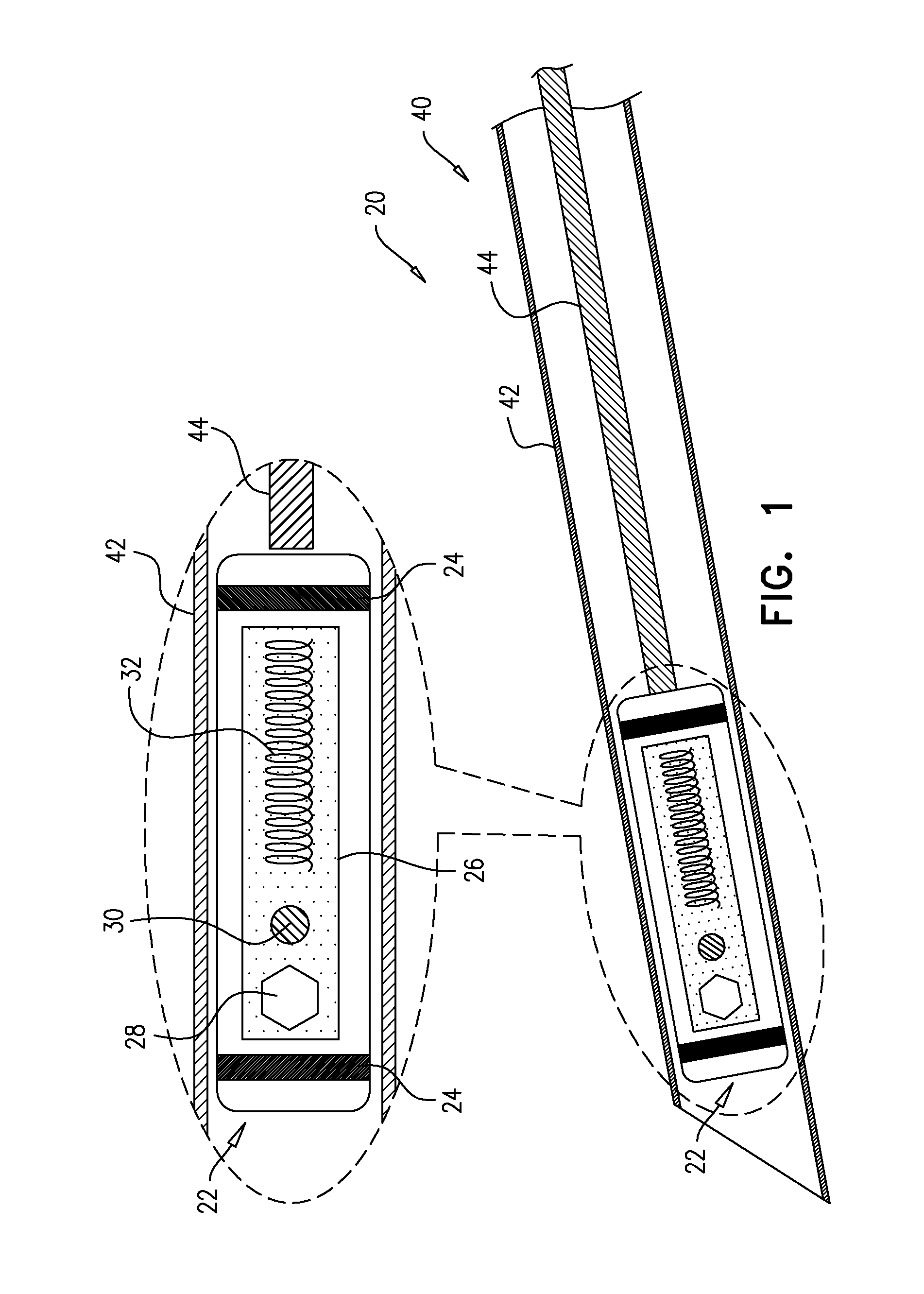
FIG. 1 is a schematic illustration of a system comprising an implant and an introducer, in accordance with some applications of the invention;
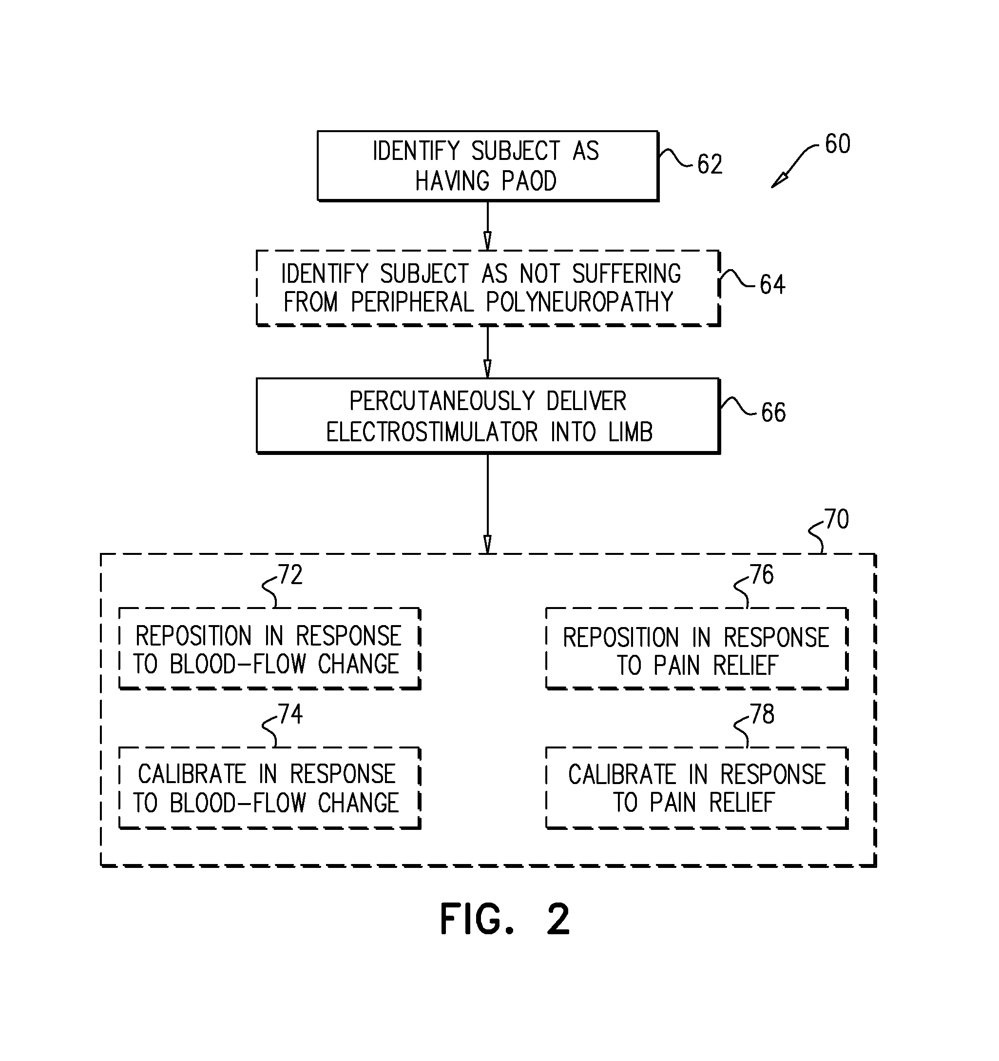
FIG. 2 is a flow chart showing at least some steps in a technique for treating a subject, in accordance with some applications of the invention;
FIG. 3 is a schematic illustration of an implant, in accordance with some applications of the invention;
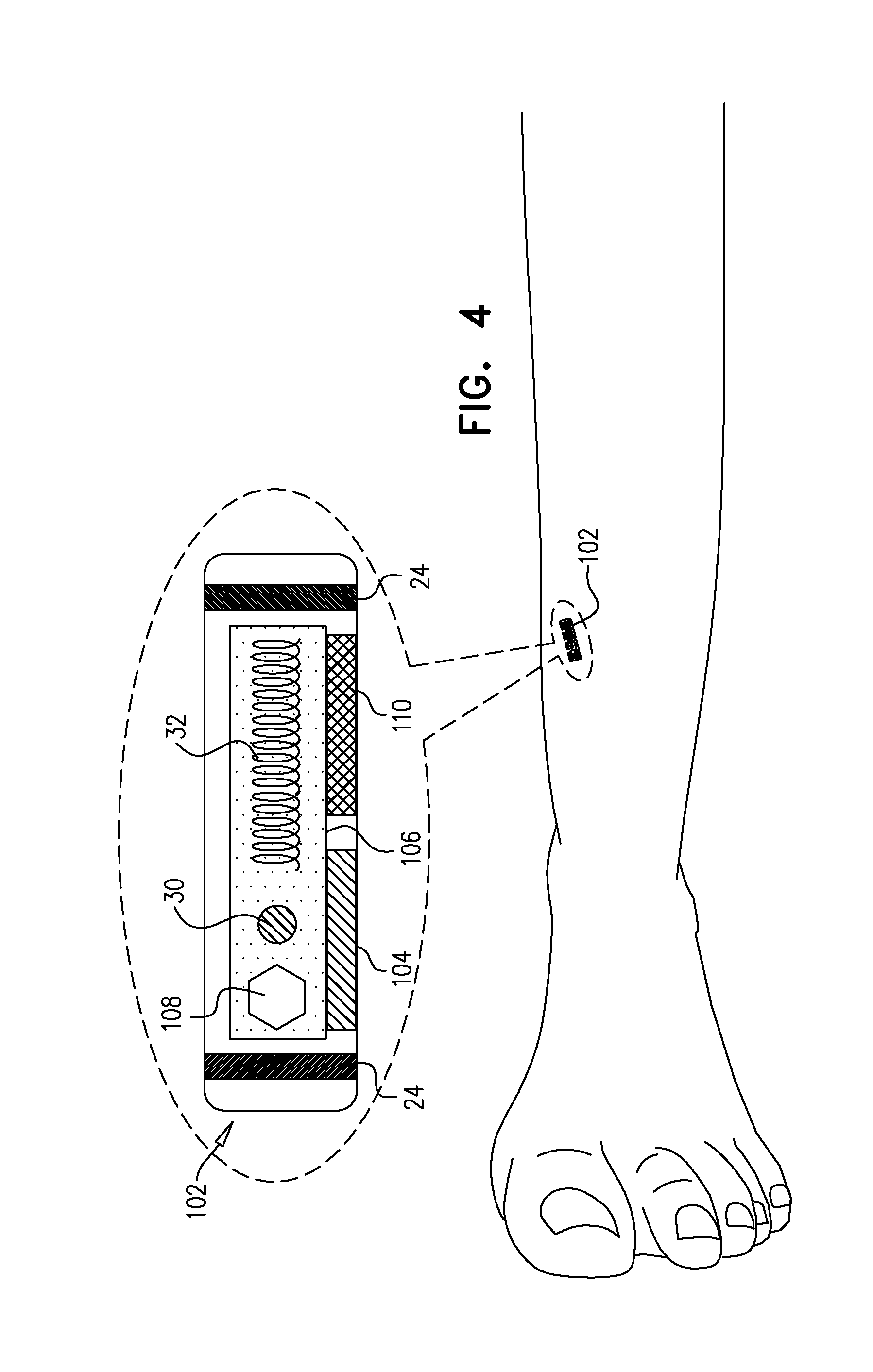
FIG. 4 is a schematic illustration of an implant 102, in accordance with some applications of the invention; and
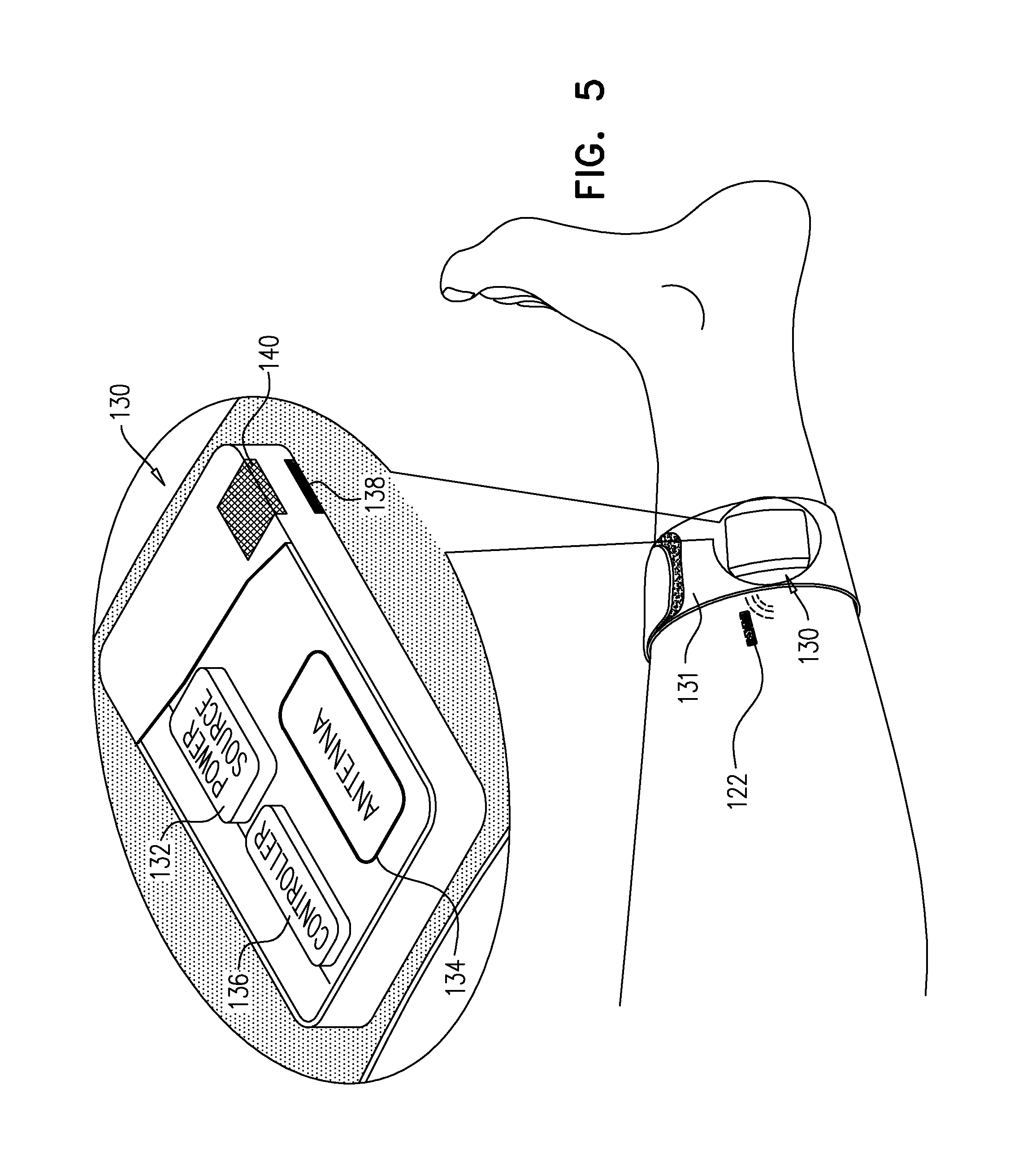
FIG. 5 is a schematic illustration of a system comprising an implant and an extracorporeal device, in accordance with some applications of the invention.
DETAILED DESCRIPTION OF EMBODIMENTS
Reference is made to FIG. 1, which is a schematic illustration of a system 20 comprising an implant 22 and an introducer 40, in accordance with some applications of the invention.
Implant 22 comprises one or more tissue-contacting electrodes 24 disposed at an outer surface of the implant, and circuitry 26 configured to drive the electrodes to apply a treatment current to tissue that is in contact with the electrodes (e.g., circuitry 26 defines and/or comprises a control unit 28). Implant 22 comprises a battery 30, or an antenna 32, or both. For some applications, implant 22 comprises a power source, such as a primary battery, and does not comprise an antenna. For some applications, antenna 32 is configured to receive wireless power. For some such applications, the received wireless power is used by circuitry 26 to recharge battery 30. For some such applications, the received wireless power is used by circuitry 26 to immediately (e.g., within 1 second of receiving the wireless power) drive electrodes 24 to apply the treatment current. For example, implant 22 may not comprise battery 30 or another non-transient power source (although the implant may comprise a capacitor).
Introducer 40 comprises a tube 42 that defines a lumen and is percutaneously-advanceable into a subject. The lumen of tube 42 is dimensioned to house implant 22 at least temporarily. Introducer 40 is configured to deploy the implant from a distal end of the lumen by moving the implant and the distal end of the lumen relative to each other. For example, once implant 22 is disposed inside the subject, within a distal portion of the introducer, tube 42 may be withdrawn proximally while a reference-force rod 44, reversibly coupled to the implant, and slidable with respect to tube 42, holds the implant stationary by providing a reference force to the implant. Alternatively, rod 44 may push implant 22 out of the distal end of tube 42 while the tube is maintained stationary.
Typically, implant 22 has a transverse cross-sectional area (i.e., transverse to the longitudinal axis of the implant along which the implant is injected) of 0.5-8 mm^2 (e.g., 1-4 mm^2).
Reference is made to FIG. 2, which is a flow chart showing at least some steps in a technique 60 for treating a subject, in accordance with some applications of the invention. A subject is identified as having peripheral artery occlusive disease (PAOD) (step 62).
Typically, the subject has been previously diagnosed with PAOD (e.g., independently and/or elsewhere), and step 62 is performed by inspecting the medical records of the subject. Alternatively, step 62 may comprise one or more diagnostic techniques. For some applications, the identification of the subject as having PAOD is performed using infrared emission information, e.g., based on infrared emission from a limb of the subject. For example, thermographic imaging or an infrared thermometer may be used. For some applications, the identification of the subject as having PAOD is performed by measuring the temperature of a limb of the subject using contact-based techniques. For some applications, the identification of the subject as having PAOD is performed using Doppler information that is indicative of blood flow in a limb of the subject. For some applications, ultrasound or laser technologies may be used to identify PAOD. For some applications, transcutaneous oximetry is used to identify the subject as having PAOD.
In response to the identification of the subject as having PAOD, an electrostimulator implant (e.g., implant 22) is percutaneously delivered into (e.g., implanted in) a limb of the subject (step 66).
The implant is activated such that the implant applies an electrical current to the limb. The step of activating the implant is not shown in the flowchart of FIG. 2 because activation may be performed before, during or after implantation.
Circuitry 26 (e.g., control unit 28) of implant 22 is typically configured to configure the treatment current to have a frequency of below 100 Hz (e.g., 1-100 Hz). For example, the treatment current may have a frequency of 1-10 Hz (e.g., 2-5 Hz), 7-12 Hz (e.g., 10 Hz), 15-25 Hz (e.g., 20 Hz), or 35-45 Hz (e.g., 40 Hz). It has been observed by the inventors that a current having such a frequency is capable of increasing blood flow in the subject, e.g., in the limb in which the implant is implanted. Therefore the treatment current is also referred to herein as a bloodflow-increasing current.
Typically, the implant is implanted within a leg of the subject. Further typically, the implant is typically implanted within 10 mm (e.g., within 5 mm, such as within 2 mm) of a tibial nerve of the subject, such that, when activated, the implant applies the treatment current to the tibial nerve.
For some applications, percutaneous electrodes are temporarily introduced into the subject in order to identify an implantation site for implant 22 (e.g., prior to, or as part of, step 66). For some such applications, this is performed using, mutatis mutandis, techniques described in PCT application publication WO 2014/087337 to Gross et al (e.g., with reference to FIGS. 4A-H thereof), which is incorporated herein by reference in its entirety. For some such applications, this is performed using, mutatis mutandis, techniques described in U.S. patent application Ser. No. 14/601,604 to Oron et al., which is incorporated herein by reference in its entirety.
For some applications, the implant may be repositioned or calibrated in response to changes in the subject caused by the implant (box 70). For example, at least in part responsively to a blood-flow change, implant 22 may be repositioned (step 72) or calibrated (step 74). Alternatively (e.g., for a subject that suffers from polyneuropathy in addition to PAOD) implant 22 may be configured to relieve pain (e.g., as described hereinbelow) as well as to increase blood flow, and at least in part responsively to a level of pain relief and/or of paresthesia, the implant may be repositioned (step 76) or calibrated (step 78). For some applications, both (i) a blood-flow change and (ii) a level of pain relief and/or paresthesia are identified, and the implant is repositioned and/or calibrated at least in part responsively to both (i) the blood-flow change and (ii) the level of pain relief and/or paresthesia. Blood-flow change may be detected using the same, or a different, technique to the technique used to identify the subject as having PAOD. For example, blood-flow change may be detected using one or more of the factors described hereinbelow with reference to FIGS. 4 & 5, mutatis mutandis.
For some applications, implant 22 is configured to relieve pain by inducing paresthesia. For some applications, implant 22 is configured to relieve pain via high-frequency nerve blocking.
Steps 72, 74, 76 and 78 are contained within box 70, with no arrows therebetween, so as to illustrate that these steps may be performed in any order, and may be repeated, as necessary. For some applications,
Calibration of implant 22 typically comprises changing an characteristic of the treatment current, such as amplitude, frequency and/or pulse width. Calibration is typically performed wirelessly. Repositioning of implant 22 is typically performed before the implant has been fully deployed (e.g., fully released from introducer 40). For some applications, implant 22 is repositioned using, mutatis mutandis, techniques described in PCT application publication WO 2014/087337 to Gross et al. (e.g., with reference to FIGS. 1A-3 thereof), which is incorporated herein by reference in its entirety.
For some applications, the implant is implanted in a subject that does not suffer from peripheral polyneuropathy (e.g., does not suffer from pain caused by polyneuropathy). That is, for some applications, identifying the subject comprises also identifying that the subject does not suffer from peripheral polyneuropathy (step 64).
Reference is made to FIG. 3, which is a schematic illustration of an implant 82, in accordance with some applications of the invention. Implant 82 is identical to implant 22, except where noted, and may be used with techniques described herein as described for implant 22, mutatis mutandis. Implant 82 is typically used in subjects that suffer from both PAOD and polyneuropathy.
Circuitry 86 (e.g., a control unit 88 thereof) of implant 82 is configured to alternate the implant between a first mode in which the implant applies a first current, and a second mode in which the implant applies a second current that differs in at least one characteristic (such as, but not limited to, frequency, amplitude, or pulse width) from the first current. Box 84 schematically illustrates this alternating between the first and second modes. The first current is the bloodflow-increasing current described hereinabove, and the second current is configured to induce pain relief. For some applications, the implant is calibrated to adjust one or both of the currents for the particular subject. For some applications, implant 82 remains in the first mode for a duration of 1-30 min (e.g., 2-20 min, such as 5-15 min). For some applications, implant 82 remains in the second mode for a duration of 1-30 min (e.g., 2-20 min, such as 5-15 min). The duration of the first mode may be the same as, or different from, the duration of the second mode.
As described hereinabove, the bloodflow-increasing first current has a frequency of 1-100 Hz. For applications in which pain relief is provided by inducing paresthesia, the second current may also have a frequency of 1-100 Hz. For applications in which pain relief is provided by high frequency nerve blocking, the second current typically has a frequency of 1-10 kHz.
Reference is made to FIG. 4, which is a schematic illustration of an implant 102, in accordance with some applications of the invention. Implant 102 is identical to implant 22, except where noted, and may be used with techniques described herein as described for implant 22, mutatis mutandis. Implant 102 comprises at least one sensor, configured to detect a respective factor indicative of local blood supply (e.g., indicative of blood perfusion to the tissue in which the implant is disposed, or indicative of blood flow through a nearby artery). For illustrative purposes, implant 102 is shown as having a first sensor 104 and a second sensor 110. Circuitry 106 (e.g., a control unit 108 thereof) of implant 102 is configured to drive electrodes 24 to apply the bloodflow-increasing current to the tissue at least in part responsively to the detected factor, typically so as to provide feedback-based treatment as required.
For some applications, one of sensors 104 and 110 is a temperature sensor, configured to detect temperature of the tissue in which the implant is implanted. For such applications, circuitry 106 (e.g., a control unit 108 thereof) of implant 102 is configured to drive electrodes 24 to apply the bloodflow-increasing current to the tissue at least in part responsively to the detected temperature, typically if the detected temperature drops below a threshold temperature, the drop in temperature being indicative of reduced blood flow in the limb.
For some applications, one of sensors 104 and 110 is configured to detect an oxygen saturation in the tissue in which the implant is disposed. For example, the sensor may be an oximeter. For such applications, circuitry 106 (e.g., control unit 108) is configured to drive electrodes 24 to apply the blood-flow increasing current at least in part responsively to the detected oxygen saturation. For example, at least in part responsively to the detected oxygen saturation being indicative of reduced blood flow in the limb (e.g., being lower than a threshold saturation), circuitry 106 (e.g., control unit 108) drives electrodes 24 to apply the bloodflow-increasing current.
For some applications, one of sensors 104 and 110 is a pressure sensor, configured to detect a blood pressure factor. For such applications, circuitry 106 (e.g., control unit 108) is configured to drive electrodes 24 to apply the blood-flow increasing current at least in part responsively to the detected blood pressure factor. For some such applications, the detected blood pressure factor comprises pulse pressure, and circuitry 106 (e.g., control unit 108) is configured to drive electrodes 24 to apply the bloodflow-increasing current at least in part responsively to the detected pulse pressure. For example, at least in part responsively to the detected blood pressure factor (e.g., pulse pressure) being indicative of reduced blood flow in the limb, circuitry 106 (e.g., control unit 108) drives electrodes 24 to apply the bloodflow-increasing current.
For some applications, one of sensors 104 and 110 is an accelerometer, configured to detect movement of the implant caused by expansion of an artery of the limb in which the implant is disposed. For such applications, circuitry 106 (e.g., control unit 108) is configured to drive electrodes 24 to apply the blood-flow increasing current at least in part responsively to the detected movement. For example, at least in part responsively to the detected movement being indicative of reduced blood flow in the limb, circuitry 106 (e.g., control unit 108) drives electrodes 24 to apply the bloodflow-increasing current. For such applications, circuitry 106 (e.g., control unit 108 thereof) is configured to distinguish movement of the implant caused by expansion of an artery, from movement of the implant caused by movement of the limb.
It is to be noted that implant 102 may comprise one or more of the above-described sensors, and circuitry 106 (e.g., control unit 108) may be configured to drive electrodes 24 to apply the blood-flow increasing current at least in part responsively to any combination of the detected factors.
Reference is made to FIG. 5, which is a schematic illustration of a system 120 comprising an implant 122 and an extracorporeal device 130, in accordance with some applications of the invention. Implant 122 is identical to implant 102, except where noted, and may be used with techniques described herein as described for implant 102, mutatis mutandis. Extracorporeal device 130 is configured to be attached to the limb in which implant 122 is disposed, such as by comprising a strap 131 that is extendable around the limb.
Extracorporeal device 130 comprises a power source (e.g., a battery) 132, an antenna 134, and a controller 136 that uses power from source 132 to drive antenna 134 to transmit wireless power, which is received by antenna 32 of implant 122, as described hereinabove, mutatis mutandis. For some applications, device 130 is configured to wirelessly drive (e.g., via circuitry of implant 122) one or more of the sensors (e.g., sensor 104 or sensor 110) of implant 122, and to receive from the implant information regarding the detected factor(s). At least in part responsively to this received information, controller 136 drives antenna 134 to wirelessly drive circuitry 106 (e.g., control unit 108 thereof) to drive electrodes 24 to apply the bloodflow-increasing current. That is, system 120 has similar overall functionality to implant 102, but with at least part of the information processing performed by extracorporeal device 130 rather than by the implant, thereby facilitating miniaturization of implant 122.
It is to be noted that antenna 134 may extend around part, most, or all of strap 131, so as to facilitate communication with implant 122.
For some applications, extracorporeal device 130 comprises at least one extracorporeal sensor, such as an extracorporeal sensor 138 and/or an extracorporeal sensor 140. Sensor 138 is an example of a sensor that is positioned to face the skin of the subject (e.g., to be placed in contact with the skin) when device 130 is attached to the limb, and sensor 140 is an example of a sensor that is typically positioned to face away from the skin of the subject when device 130 is attached to the limb. Typically, sensor 138 is configured to detect a factor indicative of local blood supply, and sensor 140 is configured to detect a factor of the environment. For example, for some applications, sensor 138 is an extracorporeal temperature sensor configured to detect a temperature of the limb, and sensor 140 is an extracorporeal temperature sensor configured to detect an ambient temperature. For such applications, controller 136 is configured to receive information regarding the temperature detected by at least one of the extracorporeal temperature sensors, and device 130 is configured to wirelessly drive circuitry 106 (e.g., control unit 108) of implant 122 to drive electrodes 24 to apply the bloodflow-increasing current to the tissue, at least in part responsively to the temperature detected by the at least one extracorporeal temperature sensor.
Alternatively or additionally, one or more of the extracorporeal sensors may be an oximeter, a pressure sensor, and/or an accelerometer, e.g., as described hereinabove for sensors 104 and 110, mutatis mutandis.
For some applications, the bloodflow-increasing current is driven in response to both (i) information received from the intracorporeal sensors of implant 122, and (ii) information received from the extracorporeal sensors of device 130.
For some applications, extracorporeal device 130 (e.g., controller 136 thereof) is configured to drive implant 122 to alternate between the first and second modes described with reference to FIG. 3, mutatis mutandis.
Reference is again made to FIGS. 1-5. Antennas are shown schematically, and unless described specifically, the configuration (e.g., the shape) of each antenna is not necessarily as shown. Furthermore, whereas each implant and extracorporeal device is shown as comprising a single antenna, that antenna may represent one or more antennas. For example, for some applications that single antenna performs both power transfer and information transfer, whereas for some applications, these functions are performed by distinct antennas.
Reference is again made to FIGS. 1-5. For some applications, the apparatus described herein is used with a limb that does not exhibit PAOD. For example, the apparatus may be used in a currently-unaffected limb of a subject that suffers from PAOD, or in a subject that is identified as being at increased risk of developing PAOD in the future. It is hypothesized that, for some applications, such uses of the apparatus described herein may delay or prevent the development of PAOD (or symptoms thereof) in the treated limb.
It will be appreciated by persons skilled in the art that the present invention is not limited to what has been particularly shown and described hereinabove. Rather, the scope of the present invention includes both combinations and subcombinations of the various features described hereinabove, as well as variations and modifications thereof that are not in the prior art, which would occur to persons skilled in the art upon reading the foregoing description.
* * * * *
References
D00000
D00001
D00002
D00003
D00004
D00005
XML
uspto.report is an independent third-party trademark research tool that is not affiliated, endorsed, or sponsored by the United States Patent and Trademark Office (USPTO) or any other governmental organization. The information provided by uspto.report is based on publicly available data at the time of writing and is intended for informational purposes only.
While we strive to provide accurate and up-to-date information, we do not guarantee the accuracy, completeness, reliability, or suitability of the information displayed on this site. The use of this site is at your own risk. Any reliance you place on such information is therefore strictly at your own risk.
All official trademark data, including owner information, should be verified by visiting the official USPTO website at www.uspto.gov. This site is not intended to replace professional legal advice and should not be used as a substitute for consulting with a legal professional who is knowledgeable about trademark law.