Content-based deduplicated storage having multilevel data cache
Schneider , et al. July 30, 2
U.S. patent number 10,366,011 [Application Number 15/970,243] was granted by the patent office on 2019-07-30 for content-based deduplicated storage having multilevel data cache. This patent grant is currently assigned to EMC IP Holding Company LLC. The grantee listed for this patent is EMC IP Holding Company LLC. Invention is credited to Amitai Alkalay, Assaf Natanzon, Zvi Schneider.


| United States Patent | 10,366,011 |
| Schneider , et al. | July 30, 2019 |
Content-based deduplicated storage having multilevel data cache
Abstract
Methods and apparatus for a content-based deduplicated storage system for generating an address to hash (A2H) value for a control module as data blocks are received and generating, for a data module, hash to physical (H2P) values corresponding to the A2H values. A first cache can be provided for the control module, where the first cache can comprise an address value, a hash value, and physical location information. A second cache can be provided for the data module, where the second cache can comprise a bucket value, a hash value, and a filter mechanism, where the filter mechanism is configured to determine whether the hash value is present.
| Inventors: | Schneider; Zvi (Tel Aviv, IL), Alkalay; Amitai (Kadima, IL), Natanzon; Assaf (Tel Aviv, IL) | ||||||||||
|---|---|---|---|---|---|---|---|---|---|---|---|
| Applicant: |
|
||||||||||
| Assignee: | EMC IP Holding Company LLC
(Hopkinton, MA) |
||||||||||
| Family ID: | 67394246 | ||||||||||
| Appl. No.: | 15/970,243 | ||||||||||
| Filed: | May 3, 2018 |
| Current U.S. Class: | 1/1 |
| Current CPC Class: | G06F 12/0811 (20130101); G06F 12/0891 (20130101); G06F 12/0246 (20130101); G06F 12/1018 (20130101); G06F 2212/62 (20130101); G06F 2212/1044 (20130101); G06F 2212/7201 (20130101); G06F 2212/202 (20130101) |
| Current International Class: | G06F 12/00 (20060101); G06F 12/0891 (20160101); G06F 12/0811 (20160101); G06F 12/02 (20060101) |
References Cited [Referenced By]
U.S. Patent Documents
| 6453319 | September 2002 | Mattis et al. |
| 7203741 | April 2007 | Marco et al. |
| 7613890 | November 2009 | Meiri |
| 7719443 | May 2010 | Natanzon |
| 7840536 | November 2010 | Ahal et al. |
| 7840662 | November 2010 | Natanzon |
| 7844856 | November 2010 | Ahal et al. |
| 7860836 | December 2010 | Natanzon et al. |
| 7882286 | February 2011 | Natanzon et al. |
| 7934262 | April 2011 | Natanzon et al. |
| 7958372 | June 2011 | Natanzon |
| 8037162 | October 2011 | Marco et al. |
| 8041940 | October 2011 | Natanzon et al. |
| 8060713 | November 2011 | Natanzon |
| 8060714 | November 2011 | Natanzon |
| 8103937 | January 2012 | Natanzon et al. |
| 8108634 | January 2012 | Natanzon et al. |
| 8214612 | July 2012 | Natanzon |
| 8250149 | August 2012 | Marco et al. |
| 8271441 | September 2012 | Natanzon et al. |
| 8271447 | September 2012 | Natanzon et al. |
| 8332687 | December 2012 | Natanzon et al. |
| 8335761 | December 2012 | Natanzon |
| 8335771 | December 2012 | Natanzon et al. |
| 8341115 | December 2012 | Natanzon et al. |
| 8370648 | February 2013 | Natanzon |
| 8380885 | February 2013 | Natanzon |
| 8392680 | March 2013 | Natanzon et al. |
| 8429362 | April 2013 | Natanzon et al. |
| 8433869 | April 2013 | Natanzon et al. |
| 8438135 | May 2013 | Natanzon et al. |
| 8464101 | June 2013 | Natanzon et al. |
| 8478955 | July 2013 | Natanzon et al. |
| 8495304 | July 2013 | Natanzon et al. |
| 8510279 | August 2013 | Natanzon et al. |
| 8521691 | August 2013 | Natanzon |
| 8521694 | August 2013 | Natanzon |
| 8543609 | September 2013 | Natanzon |
| 8583885 | November 2013 | Natanzon |
| 8600945 | December 2013 | Natanzon et al. |
| 8601085 | December 2013 | Ives et al. |
| 8627012 | January 2014 | Derbeko et al. |
| 8683592 | March 2014 | Dotan et al. |
| 8694700 | April 2014 | Natanzon et al. |
| 8706700 | April 2014 | Natanzon et al. |
| 8712962 | April 2014 | Natanzon et al. |
| 8719497 | May 2014 | Don et al. |
| 8725691 | May 2014 | Natanzon |
| 8725692 | May 2014 | Natanzon et al. |
| 8726066 | May 2014 | Natanzon et al. |
| 8738813 | May 2014 | Natanzon et al. |
| 8745004 | June 2014 | Natanzon et al. |
| 8751828 | June 2014 | Raizen et al. |
| 8769336 | July 2014 | Natanzon et al. |
| 8805786 | August 2014 | Natanzon |
| 8806161 | August 2014 | Natanzon |
| 8825848 | September 2014 | Dotan et al. |
| 8832399 | September 2014 | Natanzon et al. |
| 8850143 | September 2014 | Natanzon |
| 8850144 | September 2014 | Natanzon et al. |
| 8862546 | October 2014 | Natanzon et al. |
| 8892835 | November 2014 | Natanzon et al. |
| 8898112 | November 2014 | Natanzon et al. |
| 8898409 | November 2014 | Natanzon et al. |
| 8898515 | November 2014 | Natanzon |
| 8898519 | November 2014 | Natanzon et al. |
| 8914595 | December 2014 | Natanzon |
| 8924668 | December 2014 | Natanzon |
| 8930500 | January 2015 | Marco et al. |
| 8930947 | January 2015 | Derbeko et al. |
| 8935498 | January 2015 | Natanzon |
| 8949180 | February 2015 | Natanzon et al. |
| 8954673 | February 2015 | Natanzon et al. |
| 8954796 | February 2015 | Cohen et al. |
| 8959054 | February 2015 | Natanzon |
| 8977593 | March 2015 | Natanzon et al. |
| 8977826 | March 2015 | Meiri et al. |
| 8996460 | March 2015 | Frank et al. |
| 8996461 | March 2015 | Natanzon et al. |
| 8996827 | March 2015 | Natanzon |
| 9003138 | April 2015 | Natanzon et al. |
| 9026696 | May 2015 | Natanzon et al. |
| 9031913 | May 2015 | Natanzon |
| 9032160 | May 2015 | Natanzon et al. |
| 9037818 | May 2015 | Natanzon et al. |
| 9063910 | June 2015 | Hallak et al. |
| 9063994 | June 2015 | Natanzon et al. |
| 9069479 | June 2015 | Natanzon |
| 9069709 | June 2015 | Natanzon et al. |
| 9081754 | July 2015 | Natanzon et al. |
| 9081842 | July 2015 | Natanzon et al. |
| 9087008 | July 2015 | Natanzon |
| 9087112 | July 2015 | Natanzon et al. |
| 9104529 | August 2015 | Derbeko et al. |
| 9110914 | August 2015 | Frank et al. |
| 9116811 | August 2015 | Derbeko et al. |
| 9128628 | September 2015 | Natanzon et al. |
| 9128855 | September 2015 | Natanzon et al. |
| 9134914 | September 2015 | Derbeko et al. |
| 9135119 | September 2015 | Natanzon et al. |
| 9135120 | September 2015 | Natanzon |
| 9146878 | September 2015 | Cohen et al. |
| 9152339 | October 2015 | Cohen et al. |
| 9152578 | October 2015 | Saad et al. |
| 9152814 | October 2015 | Natanzon |
| 9158578 | October 2015 | Derbeko et al. |
| 9158630 | October 2015 | Natanzon |
| 9160526 | October 2015 | Raizen et al. |
| 9177670 | November 2015 | Derbeko et al. |
| 9189339 | November 2015 | Cohen et al. |
| 9189341 | November 2015 | Natanzon et al. |
| 9201736 | December 2015 | Moore et al. |
| 9208162 | December 2015 | Hallak et al. |
| 9223659 | December 2015 | Natanzon et al. |
| 9225529 | December 2015 | Natanzon et al. |
| 9235481 | January 2016 | Natanzon et al. |
| 9235524 | January 2016 | Derbeko et al. |
| 9235632 | January 2016 | Natanzon |
| 9244997 | January 2016 | Natanzon et al. |
| 9256605 | February 2016 | Natanzon |
| 9274718 | March 2016 | Natanzon et al. |
| 9275063 | March 2016 | Natanzon |
| 9286052 | March 2016 | Solan et al. |
| 9304889 | April 2016 | Chen et al. |
| 9305009 | April 2016 | Bono et al. |
| 9323750 | April 2016 | Natanzon et al. |
| 9330155 | May 2016 | Bono et al. |
| 9336094 | May 2016 | Wolfson et al. |
| 9336230 | May 2016 | Natanzon |
| 9367260 | June 2016 | Natanzon |
| 9378096 | June 2016 | Erel et al. |
| 9378106 | June 2016 | Ben-Moshe et al. |
| 9378219 | June 2016 | Bono et al. |
| 9378261 | June 2016 | Bono et al. |
| 9383937 | July 2016 | Frank et al. |
| 9389800 | July 2016 | Natanzon et al. |
| 9396243 | July 2016 | Halevi et al. |
| 9405481 | August 2016 | Cohen et al. |
| 9405684 | August 2016 | Derbeko et al. |
| 9405765 | August 2016 | Natanzon |
| 9411535 | August 2016 | Shemer et al. |
| 9442941 | September 2016 | Luz et al. |
| 9459804 | October 2016 | Natanzon et al. |
| 9460028 | October 2016 | Raizen et al. |
| 9471579 | October 2016 | Natanzon |
| 9477407 | October 2016 | Marshak et al. |
| 9501542 | November 2016 | Natanzon |
| 9507732 | November 2016 | Natanzon et al. |
| 9507845 | November 2016 | Natanzon et al. |
| 9514138 | December 2016 | Natanzon et al. |
| 9524218 | December 2016 | Veprinsky et al. |
| 9529885 | December 2016 | Natanzon et al. |
| 9535800 | January 2017 | Natanzon et al. |
| 9535801 | January 2017 | Natanzon et al. |
| 9547459 | January 2017 | BenHanokh et al. |
| 9547591 | January 2017 | Natanzon et al. |
| 9552405 | January 2017 | Moore et al. |
| 9557921 | January 2017 | Cohen et al. |
| 9557925 | January 2017 | Natanzon |
| 9563517 | February 2017 | Natanzon et al. |
| 9563684 | February 2017 | Natanzon et al. |
| 9575851 | February 2017 | Natanzon et al. |
| 9575857 | February 2017 | Natanzon |
| 9575894 | February 2017 | Natanzon et al. |
| 9582382 | February 2017 | Natanzon et al. |
| 9588703 | March 2017 | Natanzon et al. |
| 9588847 | March 2017 | Natanzon et al. |
| 9594822 | March 2017 | Natanzon et al. |
| 9600377 | March 2017 | Cohen et al. |
| 9619543 | April 2017 | Natanzon et al. |
| 9632881 | April 2017 | Natanzon |
| 9658983 | May 2017 | Barber et al. |
| 9665305 | May 2017 | Natanzon et al. |
| 9710177 | July 2017 | Natanzon |
| 9720618 | August 2017 | Panidis et al. |
| 9722788 | August 2017 | Natanzon et al. |
| 9727273 | August 2017 | Dantkale et al. |
| 9727429 | August 2017 | Moore et al. |
| 9733969 | August 2017 | Derbeko et al. |
| 9737111 | August 2017 | Lustik |
| 9740572 | August 2017 | Natanzon et al. |
| 9740573 | August 2017 | Natanzon |
| 9740880 | August 2017 | Natanzon et al. |
| 9749300 | August 2017 | Cale et al. |
| 9772789 | September 2017 | Natanzon et al. |
| 9798472 | October 2017 | Natanzon et al. |
| 9798490 | October 2017 | Natanzon |
| 9804934 | October 2017 | Natanzon et al. |
| 9811431 | November 2017 | Natanzon et al. |
| 9823865 | November 2017 | Natanzon et al. |
| 9823973 | November 2017 | Natanzon |
| 9832261 | November 2017 | Don et al. |
| 9846698 | December 2017 | Panidis et al. |
| 9875042 | January 2018 | Natanzon et al. |
| 9875162 | January 2018 | Panidis et al. |
| 9880777 | January 2018 | Bono et al. |
| 9881014 | January 2018 | Bono et al. |
| 9910620 | March 2018 | Veprinsky et al. |
| 9910621 | March 2018 | Golan et al. |
| 9910735 | March 2018 | Natanzon |
| 9910739 | March 2018 | Natanzon et al. |
| 9917854 | March 2018 | Natanzon et al. |
| 9921955 | March 2018 | Derbeko et al. |
| 9933957 | April 2018 | Cohen et al. |
| 9934302 | April 2018 | Cohen et al. |
| 9940205 | April 2018 | Natanzon |
| 9940460 | April 2018 | Derbeko et al. |
| 9946649 | April 2018 | Natanzon et al. |
| 9959061 | May 2018 | Natanzon et al. |
| 9965306 | May 2018 | Natanzon et al. |
| 9990256 | June 2018 | Natanzon |
| 9996539 | June 2018 | Natanzon |
| 10007626 | June 2018 | Saad et al. |
| 10019194 | July 2018 | Baruch et al. |
| 10025931 | July 2018 | Natanzon et al. |
| 10031675 | July 2018 | Veprinsky et al. |
| 10031690 | July 2018 | Panidis et al. |
| 10031692 | July 2018 | Elron et al. |
| 10031703 | July 2018 | Natanzon et al. |
| 10037251 | July 2018 | Bono et al. |
| 10042579 | August 2018 | Natanzon |
| 10042751 | August 2018 | Veprinsky et al. |
| 10055146 | August 2018 | Natanzon et al. |
| 10055148 | August 2018 | Natanzon et al. |
| 10061666 | August 2018 | Natanzon et al. |
| 10067694 | September 2018 | Natanzon et al. |
| 10067837 | September 2018 | Natanzon et al. |
| 10078459 | September 2018 | Natanzon et al. |
| 10082980 | September 2018 | Cohen et al. |
| 10083093 | September 2018 | Natanzon et al. |
| 10095489 | October 2018 | Lieberman et al. |
| 10101943 | October 2018 | Ayzenberg et al. |
| 10108356 | October 2018 | Natanzon et al. |
| 10108507 | October 2018 | Natanzon |
| 10108645 | October 2018 | Bigman et al. |
| 10114581 | October 2018 | Natanzon et al. |
| 10120787 | November 2018 | Shemer et al. |
| 10120925 | November 2018 | Natanzon et al. |
| 10126946 | November 2018 | Natanzon et al. |
| 10133874 | November 2018 | Natanzon et al. |
| 10140039 | November 2018 | Baruch et al. |
| 10146436 | December 2018 | Natanzon et al. |
| 10146639 | December 2018 | Natanzon et al. |
| 10146675 | December 2018 | Shemer et al. |
| 10146961 | December 2018 | Baruch et al. |
| 10148751 | December 2018 | Natanzon |
| 10152246 | December 2018 | Lieberman et al. |
| 10152267 | December 2018 | Ayzenberg et al. |
| 10152384 | December 2018 | Amit et al. |
| 10157014 | December 2018 | Panidis et al. |
| 10185583 | January 2019 | Natanzon et al. |
| 10191677 | January 2019 | Natanzon et al. |
| 10191687 | January 2019 | Baruch et al. |
| 10191755 | January 2019 | Natanzon et al. |
| 10203904 | February 2019 | Natanzon et al. |
| 10210073 | February 2019 | Baruch et al. |
| 10223007 | March 2019 | Natanzon et al. |
| 10223023 | March 2019 | Natanzon et al. |
| 10223131 | March 2019 | Lieberman et al. |
| 10229006 | March 2019 | Natanzon et al. |
| 10229056 | March 2019 | Panidis et al. |
| 2012/0260021 | October 2012 | Rudelic |
| 2014/0281110 | September 2014 | Duluk, Jr. et al. |
Other References
|
US. Appl. No. 16/052,037, filed Aug. 1, 2018, Schneider, et al. cited by applicant . U.S. Appl. No. 15/971,153, filed May 4, 2018, Meiri et al. cited by applicant . U.S. Appl. No. 15/971,310, filed May 4, 2018, Kucherov et al. cited by applicant . U.S. Appl. No. 15/971,325, filed May 4, 2018, Kucherov et al. cited by applicant . U.S. Appl. No. 14/496,783, filed Sep. 25, 2014, Natanzon et al. cited by applicant . U.S. Appl. No. 14/496,790, filed Sep. 25, 2014, Cohen et al. cited by applicant . U.S. Appl. No. 14/559,036, filed Dec. 3, 2014, Natanzon et al. cited by applicant . U.S. Appl. No. 14/753,389, filed Jun. 29, 2015, Nir et al. cited by applicant . U.S. Appl. No. 14/976,719, filed Dec. 21, 2015, Natanzon. cited by applicant . U.S. Appl. No. 14/978,378, filed Dec. 22, 2015, Bigman et al. cited by applicant . U.S. Appl. No. 15/085,148, filed Mar. 30, 2016, Baruch et al. cited by applicant . U.S. Appl. No. 15/274,362, filed Sep. 23, 2016, Baruch et al. cited by applicant . U.S. Appl. No. 15/275,768, filed Sep. 26, 2016, Natanzon et al. cited by applicant . U.S. Appl. No. 15/275,756, filed Sep. 26, 2016, Natanzon et al. cited by applicant . U.S. Appl. No. 15/379,940, filed Dec. 15, 2016, Baruch et al. cited by applicant . U.S. Appl. No. 15/386,754, filed Dec. 21, 2016, Shemer et al. cited by applicant . U.S. Appl. No. 15/380,013, filed Dec. 15, 2016, Baruch et al. cited by applicant . U.S. Appl. No. 15/390,996, filed Dec. 27, 2016, Natanzon et al. cited by applicant . U.S. Appl. No. 15/391,030, filed Dec. 27, 2016, Shemer et al. cited by applicant . U.S. Appl. No. 16/048,763, filed Jul. 30, 2018, Schneider et al. cited by applicant . U.S. Appl. No. 16/050,400, filed Jul. 31, 2018, Alkalay et al. cited by applicant . U.S. Appl. No. 16/179,295, filed Nov. 2, 2018, Natanzon et al. cited by applicant . U.S. Appl. No. 16/261,174, filed Jan. 29. 2019, Natanzon et al. cited by applicant . U.S. Non-Final Office Action dated May 2, 2019 for U.S. Appl. No. 15/971,310; 31 Pages. cited by applicant. |
Primary Examiner: Gu; Shawn X
Attorney, Agent or Firm: Daly Crowley Mofford & Durkee, LLP
Claims
What is claimed is:
1. A method, comprising: generating address to hash (A2H) values for a control module as data blocks are received; generating, for a data module, hash to physical (H2P) values corresponding to the A2H values; providing a first cache for the control module, the first cache comprising an address value, a hash value, and physical location information; and providing a second cache for the data module having a bucket value, a hash cache, and a filter mechanism, wherein the filter mechanism is configured to determine whether a hash value for a write operation exists.
2. The method according to claim 1, wherein the first cache uses prefetching based on offset values.
3. The method according to claim 1, wherein the filter mechanism comprises a bloom filter.
4. The method according to claim 3, wherein the bloom filter enables write operations without accessing meta data on disk.
5. The method according to claim 3, wherein the bloom filter corresponds to a bucket, where a bucket corresponds to a hash space.
6. The method according to claim 3, further including rebuilding the bloom filter when reaching a threshold of dirty entries.
7. The method according to claim 1, wherein the second cache includes an eviction mechanism for retaining entries having higher reference counts.
8. The method according to claim 7, wherein a reference count corresponds to a number of volumes having a given hash value.
9. The method according to claim 7, further including caching hash values having reference counts at or above a given value at an address to hash level to avoid double caching.
10. The method according to claim 1, further including for an incoming write, determining whether a hash for the incoming write exists in the filter mechanism, and, if the hash for the incoming write does not exist in the filter mechanism, writing data for the incoming write to disk.
11. The method according to claim 10, when the hash for the incoming write does exist in the filter mechanism, retrieving a full hash value for the hash that exists in the filter mechanism.
12. The method according to claim 1, wherein the filter mechanism comprises a bloom filter, wherein the bloom filter corresponds to a superbucket, where a superbucket corresponds to a hash space, wherein a superbucket comprises a logical aggregation of buckets, and further including using the superbucket to detect hash collisions.
13. An article, comprising: a non-transitory computer-readable medium having stored instructions that enable a machine to perform: generating address to hash (A2H) values for a control module as data blocks are received; generating, for a data module, hash to physical (H2P) values corresponding to the A2H values; providing a first cache for the control module, the first cache comprising an address value, a hash value, and physical location information; and providing a second cache for the data module having a bucket value, a hash cache, and a filter mechanism, wherein the filter mechanism is configured to determine whether a hash value for a write operation exists.
14. The article according to claim 13, wherein the first cache uses prefetching based on offset values.
15. The article according to claim 13, wherein the filter mechanism comprises a bloom filter, wherein the bloom filter corresponds to a bucket, wherein the bucket corresponds to a hash space.
16. The article according to claim 15, further including rebuilding the bloom filter when reaching a threshold of dirty entries.
17. The article according to claim 13, wherein the second cache includes an eviction mechanism for retaining entries having higher reference counts.
18. The article according to claim 13, further including instructions for determining, for an incoming write, whether a hash for the incoming write exists in the filter mechanism, and, if the hash for the incoming write does not exist in the filter mechanism, writing data for the incoming write to disk.
19. The article according to claim 18, when the hash for the incoming write does exist in the filter mechanism, retrieving a full hash value for the hash that exists in the filter mechanism.
20. A content-based storage system with deduplication, comprising: a processor and memory configured to: generate address to hash (A2H) values for a control module as data blocks are received; generate, for a data module, hash to physical (H2P) values corresponding to the A2H values; provide a first cache for the control module, the first cache comprising an address value, a hash value, and physical location information; and provide a second cache for the data module having a bucket value, a hash cache, and a filter mechanism, wherein the filter mechanism is configured to determine whether a hash value for a write operation exists.
Description
BACKGROUND
Storage systems provide content-based deduplicated data storage in which data block addresses may be generated from data content. As the costs of solid-state memory decrease, organizations can consider using systems that can store and process terabytes of data.
SUMMARY
Embodiments of the invention provide a content-based storage system with caches to promote efficient operation. In embodiments, the system has a first layer for mapping addresses in a volume to a hash value of the data and a second layer for mapping the hash values to a physical location of deduplicated data. In embodiments, the first layer may comprise a first cache having an address, a hash generated from data, and physical location components so that it may not be necessary to obtain the physical location from the second layer. In embodiments, the second layer may comprise a second cache having a filter mechanism to identify the presence of a hash value, a hash value, and a bucket identifier. A bucket can form part of a hash table structure that represents a hash space. The second cache can efficiently determine whether a hash value is present to minimize accesses to meta data on disk for write operations, for example.
In one aspect, a method comprises generating an address to hash (A2H) value for a control module as data blocks are received; generating, for a data module, hash to physical (H2P) values corresponding to the A2H values; providing a first cache for the control module, the first cache comprising an address value, a hash value, and physical location information; and providing a second cache for the data module having a bucket value, a hash value, and a filter mechanism, wherein the filter mechanism is configured to determine whether the hash value is present.
BRIEF DESCRIPTION OF THE DRAWINGS
The foregoing features of this invention, as well as the invention itself, may be more fully understood from the following description of the drawings in which:
FIG. 1A is a block diagram of a content-based storage system having multi-level cache for deduplicated storage;
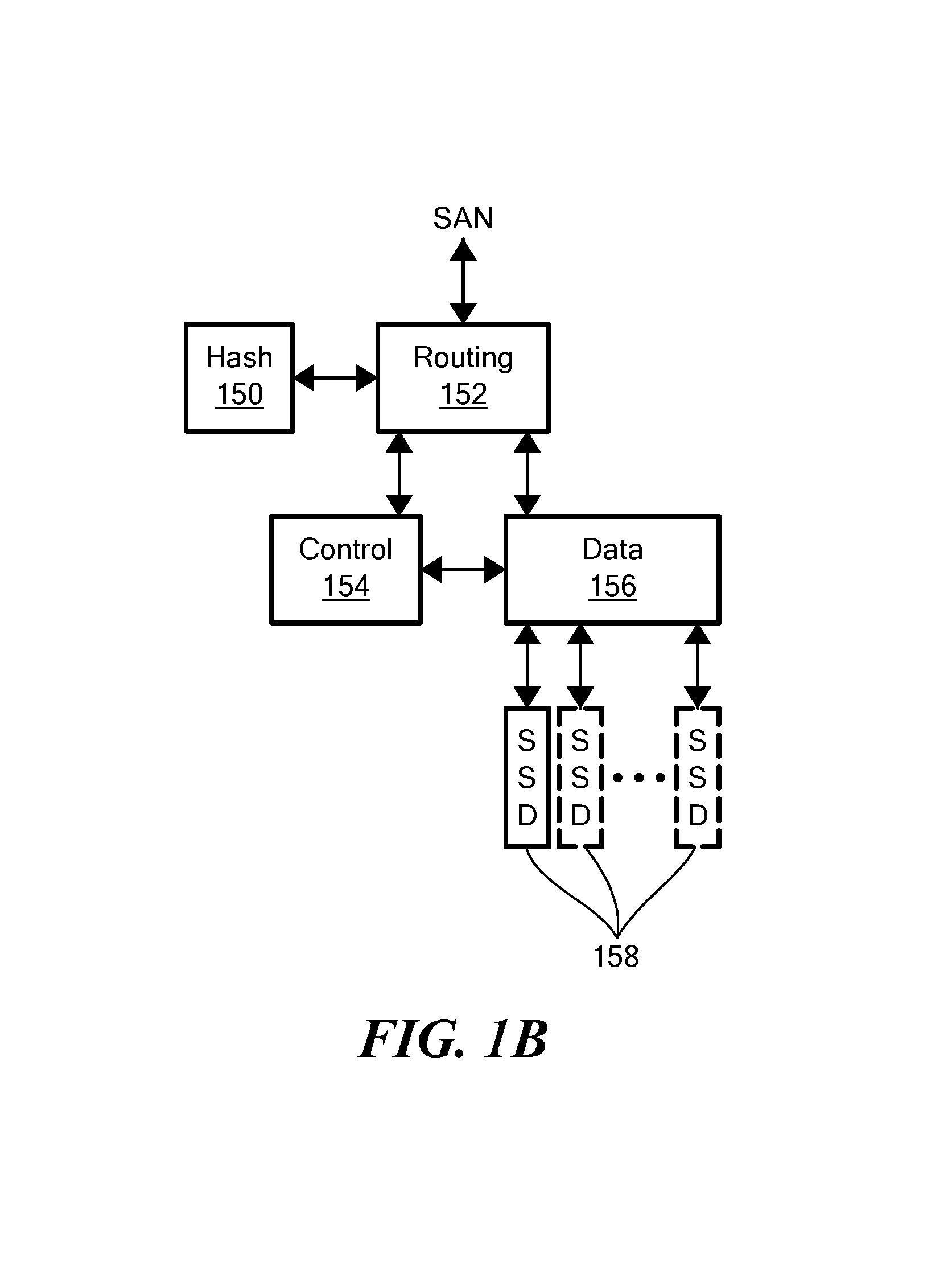
FIG. 1B shows further detail of the system of FIG. 1B;
FIG. 2 is a flow diagram of read and write operations for the system of FIG. 1A;
FIG. 3 is a block diagram of a content-based storage system having a control module with a first cache and a data module with a second cache;
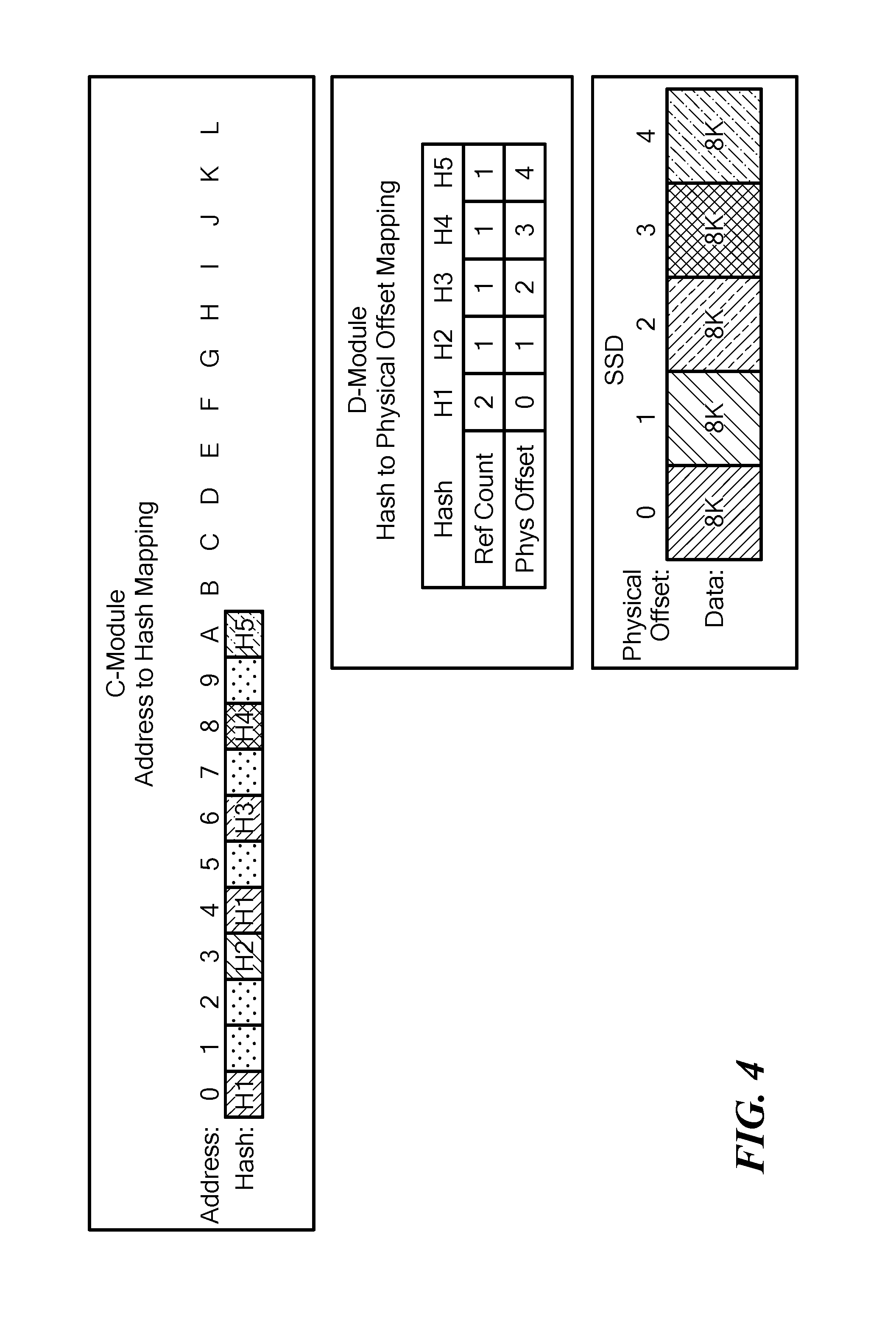
FIG. 4 is a schematic representation of address-to-hash (A2H) mapping in a control module and hash-to-physical (H2P) mapping in a data module for a content-based storage system;
FIG. 5A is a schematic representation of a control module cache and FIG. 5B is a schematic representation of a data module cache for a content-based storage system;
FIG. 6 is a schematic representation of bloom filters for corresponding buckets and a super bucket of aggregated buckets for identifying the presence of hash values;
FIG. 7 is a flow diagram showing an example sequence of steps for performing a write operation in a content-based storage system having a data module cache; and
FIG. 8 is a block diagram of an illustrative computer that can perform at least a portion of the processing described herein.
DETAILED DESCRIPTION
FIG. 1A shows an illustrative content-based data storage system 100 with deduplication that may have multi-level data caches in accordance with embodiments of the disclosure. In the illustrated embodiment, first, second, third, and fourth nodes 102, 104, 106, 108 can be interconnected by a switch 110 via a switch interface 111. The first node 102 can include a control system 114 and a data system 116. In embodiments, separate data and control planes may be provided by the control and data systems 114, 116. The control system 114 may control execution of read and write commands to the storage devices 112. The data systems 116 may be connected to the storage devices 112 and, under control of a respective control system 114, may pass data to and/or from the storage devices via suitable storage drivers 113.
The data and/or control systems 114, 116 may retain extracts of the data stored in the storage devices 112. In embodiments, the data extracts may be generated by cryptographic hashing of the data content in the data blocks. In embodiments, the extracts may be used for content addressing of the data blocks to the physical storage devices 112.
The second node 104 can include a hash system 117 to generate the hash/extract, which can be referred to as a content fingerprint for the data blocks. The second node 104 can also include a routing system 118, along with a switch interface 111 and a SAN interface 115. The routing system 118 may terminate storage and retrieval operations and distribute commands to control systems 114 that may be selected for the operation in such a way as to retain balanced usage within the system. In the illustrated embodiment, the third node 106 can be similar to the first node 102 and the fourth node 108 can be similar to the second node 108.
The routing systems 118 may use the hash values calculated from data blocks to select control systems 114 for distribution. More particularly, selection of the control system 114 may use hash values, or may rely on the user address and not on the content (hash). The hash value may, however, be used for selecting the data system 116, and for setting the physical location for data storage within the data system.
In example embodiments, control modules 114 can include a C cache 115 and the data modules 116 can include a D cache 117. As explained more fully below, the C cache 115 can include addresses, address hashes, and physical data location information and the D cache 117 can include, for each bucket, a filter, a hash to address, and bucket information.
In some examples, the system 100 may employ more than a single type of memory technology, including a mix of more than one Flash technology (e.g., single level cell (SLC) flash and multilevel cell (MLC) flash), and a mix of Flash and DRAM technologies. In certain embodiments, data mapping may optimize performance and life span by taking advantage of the different access speeds and different write/erase cycle limitations of the various memory technologies.
FIG. 1B is an example of a system that can include a hash system 150 communicatively coupled to a routing system 152, which can be communicatively coupled to a control system 154 and a data system 156. The data system 156 can be communicatively coupled to any practical number of memory devices 158. The routing system 152 can route read/write commands from a host (not shown) to control and data systems 154, 156 for execution. In embodiments, the data content-based mapping to physical storage 158 can distribute workload relatively evenly and provide separation of the control and data paths. Read and write operations to the SSDs 158 can be used to generate priority values for the data blocks, as described more fully below.
FIG. 2 shows an example IO operation. A host 217 may issue a read command for a logical block address, which is shown as address "6," via a Fibre Channel or iSCSI port, for example. The routing system 218 may receive the read command and determine a requested address range in data blocks of 4K, for example, and pass the address information to the control system 214.
The control system 214 may look up address 6 to obtain the hash value, which is shown as H6. This may be referred to as address-to-hash (A2H) lookup. The H6 hash value may be passed to the data system 216 which can perform a look up of the H6 hash value in a hash-to-physical address (H2P) table to read the physical address for the data. In the example, the physical address is shown as "G." The data system 216 can use the physical address to read the data block (DB) at physical address G in the SSD 221. A reference count can correspond to a number of times the hash value is referenced in physical storage. In embodiments, write reference information can be modified for each unique and/or deduplicated write and access reference information can be modified for each read and/or write access.
For a write operation from a host, the routing system 218 can receive the write data and can segment the data stream into data blocks and generate hash values for the data blocks. The hash value can be provided to the control system 214 to determine if the write data is unique. If unique, the hash value can be placed in an address mapping. The control system 214 can pass the hash value to the data system 216, which can assign the hash value to a physical address and write the data block(s) to the SSD at the physical address. In embodiments, the write reference information and/or the access reference information, can be modified, e.g., incremented,
If the hash value generated by the routing system 218 is not unique, the control system 214 can determine that data already exists at the physical address for the hash value. Since the data already exists, the data system 216 can increment the write reference information for the data block. In embodiments, the access reference information can also be modified. The data may not be written to the SSD. Deduplication may refer to a write operation where a hash for a data block is found not be unique and the non-unique data block is not written to physical storage. The reference count for the non-unique hash may be incremented.
FIG. 3 shows a storage system 300 according to an illustrative embodiment of the disclosure. The storage system 300 may be the same as or similar to a node within the distributed storage system of FIG. 1A. The storage system 300 may include a plurality of modules 302a-302d (generally denoted 302 herein), a storage array 306 comprising a plurality of storage devices 308a . . . 308n (generally denoted 308 herein), and a primary memory 318. In some embodiments, the storage devices 308 may be provided as solid-state devices (SSDs).
As described further herein, the storage system 300 also can include a C (also called logical) cache 317 and a D (also called physical) cache 323. The C cache 317 and/or the D cache 323 can, in certain embodiments, be physical devices configured to store certain data so that future requests for that data can be served faster. Although the C cache 317 and D cache 323 are shown as being part of the storage system, it is understood that the C cache 317 and/or D cache 323 can be located anywhere such that they are accessible quickly to the storage system. Data that is stored within a cache might include data values that have been computed earlier or duplicates of original values that are stored elsewhere. If the requested data is contained in the cache (herein referred to as a cache hit), this request can be served by simply reading the cache, which is comparatively faster than going to other types of memory. On the other hand, if the requested data is not contained in the cache (herein referred to as a cache miss), the data may have to be to be recomputed or fetched from its original storage location, which is comparatively slower. Hence, the greater the number of requests that can be served from the cache, the faster the overall system performance becomes.
The primary memory 318 can be any type of memory having access times that are faster compared to the storage devices 308. In some embodiments, primary memory 318 may be provided as dynamic random-access memory (DRAM). In certain embodiments, primary memory 318 may be provided as synchronous DRAM (SDRAM). In one embodiment, primary memory 318 may be provided as double data rate SDRAM (DDR SDRAM), such as DDR3 SDRAM.
As described above, the control subsystem 302b may be configured to maintain a mapping between I/O addresses associated with data and the corresponding chunk hashes. As shown in FIG. 3, this mapping may be maintained using a data structure 312, referred to herein as an "I/O address to chunk hash mapping table" or "A2H table," (also known as A.fwdarw.H table) according to some embodiments. In one embodiment, I/O addresses may be logical addresses used by clients 318 to access data within the storage system 300.
As also described above, the data subsystem 302c may be configured to maintain a mapping between chunk hashes and physical storage addresses (i.e., storage locations within the storage array 306 and/or within individual storage devices 308). This mapping may be maintained using a data structure 314, referred to herein as a "hash to physical address mapping table" or "H2P table," or "H.fwdarw.P table," according to some embodiments, where this table, in certain embodiments, includes information similar to that of the aforementioned HMD (hash metadata) and PL (physical layout) tables. In certain embodiments, as described, for example, in the incorporated by reference patents, there also may be a mapping referred to as the H2D or H.fwdarw.D table, where D stands for disk physical layout. In certain embodiments, the H2P table is maintained to route data with different hashes to different D modules. The data subsystem 302c may be also be configured to read and write data from/to the storage array 306 (and/or to individual storage devices 308 therein).
As described above, in a content addressable storage system, data is stored in blocks, for example 16 KB, 8 KB, 4 KB, etc., where each block has a universally unique large hash signature, for example of 20 bytes, which can be saved to disk, e.g., Flash memory. As described herein, hash signatures may be accessed by small in-memory handles (referred to herein as short hash handles, hash handles, or short hashes), for example of 6 bytes. These short hashes may be unique to each volume/array, but not necessarily unique across volumes/arrays. Additional information relating to hash-based replication, computation of hashes, generation and use of short hash handles can be found in U.S. Pat. No. 9,378,106 ("Hash Based Replication"); U.S. Pat. No. 9,208,162 ("Generating a Short Hash Handle") and U.S. Pat. No. 9,396,243 ("Hash-Based Replication Using Short Hash Handle and Identity Bit"), each of which is hereby incorporated by reference.
In embodiments, address to hash mapping (A2H) maps an address inside a volume to the short hash value of its data. In embodiments, meta data can include for each address the hash value of the content. If the basis for deduplication is 16 KB, then the meta data holds for each address the short hash value of the data to which the address points. In cases where access to the volume is in larger chunks than the size of the basic hash value, the meta data for the address space can be readily cached.
As also noted above, hash to physical disk locations can include for each hash key (e.g., 6 bytes) the location on the disk, and the reference count. Where a storage system uses hash keys of 6 bytes, there may be collisions of data generating the same hash. If there is a collision, a new hash key from a different hash address space is generated for the data when the data is written. This means that the hash to physical disk location table may search for a hash value every time a new write arrives. If the write has the same hash value, there is a need to check the long hash value, and verify if there is a hash collision, or whether it is actually the same data. This means that during every write if the hash to physical disk location table is not in the system memory, there may a need to fetch the meta data of the hash from the disk to verify if such a hash exists. It will be appreciated that meta data structures may consume most of system memory, e.g., DRAM, in the storage system, so that the meta data limits the total size of the storage system.
FIG. 4 shows an example control or C module address to hash (A2H) mapping 400. As can be seen, as data blocks arrive, the content for the address is hashed to generate H1, H2, H3, H4, H5, as shown. It should be noted that H1 appears twice and is deduplicated. The D-module includes a hash to physical (H2P) mapping showing the physical offset of the data along with a reference count indicative of how many times a given hash value occurs. It will be appreciated that a particular hash value having a high reference count will likely be accessed more often than hash values having a low reference count. In embodiments, a reference count is incremented each time the hash value is generated in a volume. Thus, higher reference count hash values may be preferred for placement in D cache over low reference count hash values. It can be seen that the physical offset corresponds to the order in which a unique hash value is generated. For example, H3 is shown with an offset value of 2 since a second H1 value was deduplicated.
In embodiments, for a particular volume, an address to hash mapping maps an address inside the volume to the short hash value of its data. In embodiments, meta data includes for each address the hash value of the content. If the basis for deduplication is 16 KB, then the meta data holds, for each address, the short hash value of the data to which the address points. In cases where access to the volume is in larger chunks than the size of the basic hash value, the meta data for the address space can be cached. Any suitable caching algorithm can be used, such as LRU (least recently used). For example, read accesses may be sequential with so-called hot spots for certain access areas. A system can implement a C cache for the meta data of the a.fwdarw.h table by using LRU caching with prefetching of nearby meta data. In embodiments, the full A.fwdarw.H table will be stored on the disk.
FIG. 5A shows an example C cache configuration for control modules, such as the control module 114 of FIG. 1A. In embodiments, a C cache 500 includes an address 502, a hash value for the address 504, and physical location 506 matching the hash value 504. In embodiments, the hash value 504 corresponds to a short hash value and the long hash value is stored in disk memory.
With this arrangement, when there is a cache hit for the meta data in the A2H map for the C cache 500, there is no need to look for the location of the data matching the hash, since the physical address 506 for the hash is immediately available. It will be appreciated that this is applicable for read commands, since write commands generate a new hash value. In embodiments, the physical address may be kept for some entries and not kept for other entries.
FIG. 5B shows an example D cache 550 having a bloom filter 552, a cache of hash values 554, and a bucket identifier 556. For write operations, the D cache enables the system to efficiently determine whether a hash value exists without accessing meta data on disk unless needed. In example embodiments, a Bloom filter 552 is used to determine whether a hash value is present for a given write operation. As is well known, a Bloom filter is a space efficient probabilistic data structure for testing whether an element is member of a set. While false positive matches may occur, false negatives will not. That is, the result is a `may be in the set` or `definitely not in the set.` Elements can be added but not removed from the Bloom filter.
While in illustrative embodiments a Bloom filter is used to determine whether a give hash value exists, it is understood that any suitable mechanism can be used to determine whether a given value is present.
It will be appreciated that caching the hash to physical (H2P) location does not have the locality features of the A2H mapping, which data is typically close in space. Thus, prefetching data for the cache is impractical from the hash space directly. The value of caching entries in the hash space can be based on how popular the entry is based upon the reference count, for example, where the reference count is incremented each volume containing a given short hash value
Within a single entry one can hash for the relevant volumes sharing the hash so as to create a more compact hash table.
FIG. 6 shows an example in which each bucket B has a corresponding Bloom filter BF and a superbucket SB is a logical aggregation of buckets. In embodiments, a bucket B in the hash table data structure of the D cache represents a given hash space comprising some set of hash values. Since data cannot be deleted from Bloom filters, in embodiments many bloom filters are used. In embodiments, false positive data, i.e., an incorrect indication from the bloom filter that a hash value exists, can be used to determine whether to rebuild the Bloom filter, which can be performed efficiently while searching demoted data. When a certain threshold, e.g., 20%, is met where the bloom filter incorrectly indicates the hash is present, the bloom filter can be rebuilt.
FIG. 7 shows an example write operation that provides an efficient mechanism for checking if a hash value exists, without accessing disk memory. The bloom filter indicates for each write whether data with the same hash exists. If so, we can check if the hash value exists in a "hash to physical disk meta data cache. In embodiments, the full hashes can be kept in the hash cache, and if the data is not in the cache, we can look for the full hash in the disk. In embodiments, as writes occur hash values may reside in cache prior to being added to the bloom filter since some cache entries may be short lived in the cache.
In step 700, it is determined whether the hash value exists by checking the Bloom filter for the bucket. If the bloom filter indicates the hash exists, in step 702, it is determined whether the hash value exists in the meta data cache, e.g., the D cache. If not, in step 704, where the hash value exists, but not in the meta data cache for the H2P table, one can read the meta data for the super bucket (see SB FIG. 6) and look for the identical hash value.
In step 706, after analyzing the super bucket meta data it is determined whether there is a hash collision, which will not happen in most cases in example embodiments. If there is no collision, in step 708, the write can occur without fetching meta data from the disk. If there was a hash collision, in step 710 the long hash information on disk can be accessed to determine whether the hash is for a same or different data content.
It will be appreciated that while smaller bloom filters may be somewhat less efficient, they enable processing to quickly handle deletes by rebuilding bloom filters. It will be appreciated as write operations continue to occur over time the Bloom filter will contain more and more inaccurate entries and can be rebuilt.
In embodiments, there is a preference for entries having a higher reference count in the hash cache. Entries which are popular but have only one reference may be cached at the A2H level, and thus this can avoid double caching, e.g., entries with a reference count of 1 will be removed from cache with higher probability.
In embodiments, new entries will go through the hash space cache, and the bloom filter will not include hashes that are in the cache. In this way, if a hash entry is short-lived (meaning not in cache very long), the entry will be in the cache, and will not dirty/corrupt the bloom filter.
To prefer eviction of entries with low reference counts, the caching algorithm may hold a separate LRU for entries with reference count >1. Once a new entry arrives, the system can select which LRU entry needs to be evicted. In embodiments, the probability of evicting entries from the LRU with reference count=1 will be higher.
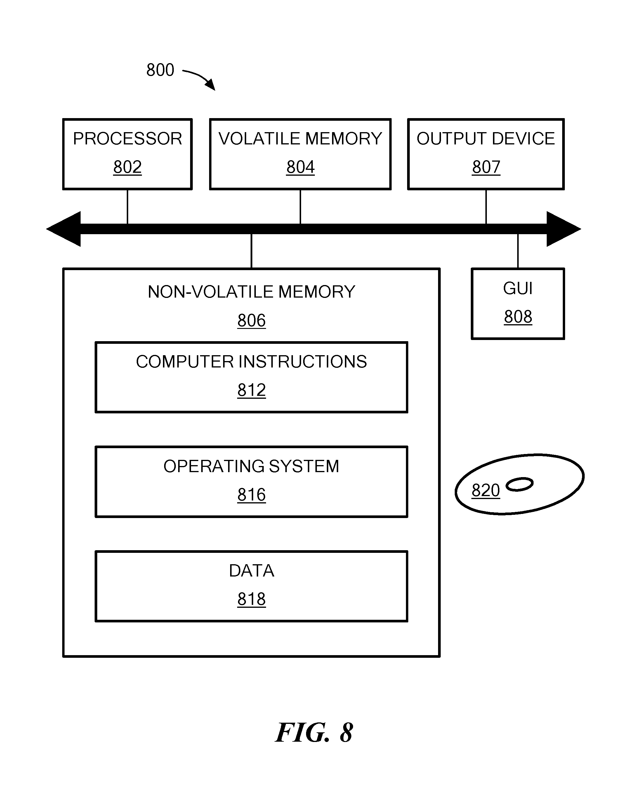
FIG. 8 shows an exemplary computer 800 (e.g., physical or virtual) that can perform at least part of the processing described herein. The computer 800 includes a processor 802, a volatile memory 804, a non-volatile memory 806 (e.g., hard disk or flash), an output device 807 and a graphical user interface (GUI) 808 (e.g., a mouse, a keyboard, a display, for example). The non-volatile memory 806 stores computer instructions 812, an operating system 816 and data 818. In one example, the computer instructions 812 are executed by the processor 802 out of volatile memory 804. In one embodiment, an article 820 comprises non-transitory computer-readable instructions.
Processing may be implemented in hardware, software, or a combination of the two. Processing may be implemented in computer programs executed on programmable computers/machines that each includes a processor, a storage medium or other article of manufacture that is readable by the processor (including volatile and non-volatile memory and/or storage elements), at least one input device, and one or more output devices. Program code may be applied to data entered using an input device to perform processing and to generate output information.
The system can perform processing, at least in part, via a computer program product, (e.g., in a machine-readable storage device), for execution by, or to control the operation of, data processing apparatus (e.g., a programmable processor, a computer, or multiple computers). Each such program may be implemented in a high level procedural or object-oriented programming language to communicate with a computer system. However, the programs may be implemented in assembly or machine language. The language may be a compiled or an interpreted language and it may be deployed in any form, including as a stand-alone program or as a module, component, subroutine, or other unit suitable for use in a computing environment. A computer program may be deployed to be executed on one computer or on multiple computers at one site or distributed across multiple sites and interconnected by a communication network. A computer program may be stored on a storage medium or device (e.g., CD-ROM, hard disk, or magnetic diskette) that is readable by a general or special purpose programmable computer for configuring and operating the computer when the storage medium or device is read by the computer. Processing may also be implemented as a machine-readable storage medium, configured with a computer program, where upon execution, instructions in the computer program cause the computer to operate.
Processing may be performed by one or more programmable processors executing one or more computer programs to perform the functions of the system. All or part of the system may be implemented as, special purpose logic circuitry (e.g., an FPGA (field programmable gate array) and/or an ASIC (application-specific integrated circuit)).
Having described exemplary embodiments of the invention, it will now become apparent to one of ordinary skill in the art that other embodiments incorporating their concepts may also be used. The embodiments contained herein should not be limited to disclosed embodiments but rather should be limited only by the spirit and scope of the appended claims. All publications and references cited herein are expressly incorporated herein by reference in their entirety. Elements of different embodiments described herein may be combined to form other embodiments not specifically set forth above. Various elements, which are described in the context of a single embodiment, may also be provided separately or in any suitable subcombination. Other embodiments not specifically described herein are also within the scope of the following claims.
* * * * *
D00000
D00001
D00002
D00003
D00004
D00005
D00006
D00007
D00008
XML
uspto.report is an independent third-party trademark research tool that is not affiliated, endorsed, or sponsored by the United States Patent and Trademark Office (USPTO) or any other governmental organization. The information provided by uspto.report is based on publicly available data at the time of writing and is intended for informational purposes only.
While we strive to provide accurate and up-to-date information, we do not guarantee the accuracy, completeness, reliability, or suitability of the information displayed on this site. The use of this site is at your own risk. Any reliance you place on such information is therefore strictly at your own risk.
All official trademark data, including owner information, should be verified by visiting the official USPTO website at www.uspto.gov. This site is not intended to replace professional legal advice and should not be used as a substitute for consulting with a legal professional who is knowledgeable about trademark law.