Display unit for vehicle
Coser , et al.
U.S. patent number 10,363,818 [Application Number 13/471,408] was granted by the patent office on 2019-07-30 for display unit for vehicle. This patent grant is currently assigned to AUDI AG, VOLKSWAGEN AG. The grantee listed for this patent is Nathaniel Coser, Erik Glaser, William Brian Lathrop, Maria Mejia. Invention is credited to Nathaniel Coser, Erik Glaser, William Brian Lathrop, Maria Mejia.


| United States Patent | 10,363,818 |
| Coser , et al. | July 30, 2019 |
Display unit for vehicle
Abstract
A display unit for a vehicle includes an electronic display and a light guide coupled to a portion of the display.
| Inventors: | Coser; Nathaniel (Palo Alto, CA), Glaser; Erik (San Francisco, CA), Lathrop; William Brian (San Jose, CA), Mejia; Maria (Palo Alto, CA) | ||||||||||
|---|---|---|---|---|---|---|---|---|---|---|---|
| Applicant: |
|
||||||||||
| Assignee: | VOLKSWAGEN AG (Wolfsburg,
DE) AUDI AG (Ingolstadt, DE) |
||||||||||
| Family ID: | 46506289 | ||||||||||
| Appl. No.: | 13/471,408 | ||||||||||
| Filed: | May 14, 2012 |
Prior Publication Data
| Document Identifier | Publication Date | |
|---|---|---|
| US 20120287664 A1 | Nov 15, 2012 | |
Related U.S. Patent Documents
| Application Number | Filing Date | Patent Number | Issue Date | ||
|---|---|---|---|---|---|
| 61486136 | May 13, 2011 | ||||
| Current U.S. Class: | 1/1 |
| Current CPC Class: | B60K 35/00 (20130101); B60K 37/02 (20130101); B60K 2370/1531 (20190501); B60K 2370/152 (20190501); B60K 2370/33 (20190501); B60K 2370/20 (20190501); B60K 2370/336 (20190501); Y10T 156/10 (20150115) |
| Current International Class: | B60K 35/00 (20060101); B60K 37/02 (20060101) |
| Field of Search: | ;362/23.01,23.09,23.16,23.18,23.19,23.2,23.21,242,489,551,436-442 ;359/242 ;385/115-121 |
References Cited [Referenced By]
U.S. Patent Documents
| 4434932 | March 1984 | Nara et al. |
| 4832427 | May 1989 | Nanba et al. |
| 5644289 | July 1997 | Frehner et al. |
| 6152066 | November 2000 | Knoll et al. |
| 6205275 | March 2001 | Melville |
| 6542146 | April 2003 | Toffolo et al. |
| 6667446 | December 2003 | Schuberth et al. |
| 7025482 | April 2006 | Yamashita et al. |
| 7056203 | June 2006 | Shibata et al. |
| 7125132 | October 2006 | Wang |
| 7190390 | March 2007 | Hett et al. |
| 7198393 | April 2007 | Tubidis et al. |
| 7232245 | June 2007 | Suzuki et al. |
| 7273278 | September 2007 | Fronzek |
| 7357095 | April 2008 | Fong et al. |
| 7357096 | April 2008 | Tane |
| 7525446 | April 2009 | Shibata |
| 7534000 | May 2009 | Adachi et al. |
| 7592972 | September 2009 | Eckardt et al. |
| 7661859 | February 2010 | Nakagawa |
| 7671851 | March 2010 | Pryor |
| 7671859 | March 2010 | Birman et al. |
| 8016441 | September 2011 | Birman et al. |
| 2001/0045278 | November 2001 | Iwamoto et al. |
| 2002/0041491 | April 2002 | Nakagawa et al. |
| 2004/0129197 | July 2004 | Nakagawa et al. |
| 2005/0212721 | September 2005 | Kuwahara et al. |
| 2006/0018109 | January 2006 | Kageyama et al. |
| 2006/0044778 | March 2006 | Muramatsu |
| 2006/0066250 | March 2006 | Wang |
| 2006/0077068 | April 2006 | Harada et al. |
| 2006/0126320 | June 2006 | Fong et al. |
| 2007/0279243 | December 2007 | Araki |
| 2008/0002388 | January 2008 | Sullivan |
| 2008/0123322 | May 2008 | Tane |
| 2008/0135206 | June 2008 | Alves et al. |
| 2008/0144174 | June 2008 | Lucente |
| 2008/0278803 | November 2008 | Kraus |
| 2009/0015736 | January 2009 | Weller et al. |
| 2009/0078190 | March 2009 | Fournier |
| 2009/0091513 | April 2009 | Kuhn |
| 2009/0219734 | September 2009 | Sawada et al. |
| 2010/0059348 | March 2010 | Hauf |
| 2011/0025488 | February 2011 | Leon |
| 2012/0057342 | March 2012 | Shih |
| 2013/0179811 | July 2013 | Nagara et al. |
| 101535087 | Sep 2009 | CN | |||
| 100 26 136 | Nov 2000 | DE | |||
| 601 03 156 | May 2005 | DE | |||
| 10 2004 041 119 | Mar 2006 | DE | |||
| 10 2005 043 205 | Mar 2007 | DE | |||
| 10 2005 043 310 | Oct 2007 | DE | |||
| 10 2007 005 362 | Feb 2008 | DE | |||
| 10 2007 056 450 | Oct 2008 | DE | |||
| 10 2008 017 051 | Oct 2009 | DE | |||
| 10 2008 032 061 | Jan 2010 | DE | |||
| 0 583 392 | Mar 1998 | EP | |||
| 1 655 750 | May 2006 | EP | |||
| 1 573 374 | Feb 2007 | EP | |||
| 1 888 974 | Feb 2008 | EP | |||
| 2008-191274 | Aug 2008 | JP | |||
| 2006/024748 | Mar 2006 | WO | |||
| 2007/053710 | May 2007 | WO | |||
| 2010/045411 | Apr 2010 | WO | |||
Other References
|
English Machine Translation of JP 2008191274 provided by Espacenet (Year: 2008). cited by examiner. |
Primary Examiner: Song; Zheng
Attorney, Agent or Firm: Hunton Andrews Kurth LLP
Parent Case Text
CROSS-REFERENCE TO RELATED APPLICATIONS
The present application claims the benefit of U.S. Provisional Patent Application Ser. No. 61/486,136, filed on May 13, 2011, which is expressly incorporated herein in its entirety by reference thereto.
Claims
What is claimed is:
1. A display unit for a vehicle, comprising: an electronic display configured to display information for an occupant of the vehicle; a light guide configured as a light pipe, having a thickness, situated adjacent to a portion of a displaying face of the display, and configured to guide light from the portion of the displaying face of the display representing a part of the information displayed on the display from a first location at the display through the thickness of the light guide, by internal reflection, to a predetermined location spaced apart from the electronic display; and a further light guide configured as a light pipe including at least one optical fiber situated adjacent to a further portion of the displaying face of the display and configured to guide light from the further portion of the displaying face of the display representing at least another part of the information to a further predetermined location spaced apart from the electronic display, the further predetermined location being different from the predetermined location; wherein a display end of the light guide is provided at a distance from the electronic display, the distance based on a dimension of the light guide, the light guided from the portion of the displaying face of the display by the light guide being displayed at the display end of the light guide closer in view than the information displayed on the display outside of the portion of the displaying face of the display situated adjacent to the light guide, such that the displayed information appears three dimensional; and wherein the light guide includes a surface provided parallel and adjacent to the portion of the displaying face of the display, the light guide further including a first portion and a second portion, a thickness of the first portion extending from the surface in a direction perpendicular to the surface being smaller than a thickness of the second portion from the surface in the direction perpendicular to the display surface of the electronic display.
2. The display unit according to claim 1, wherein the first portion and the second portion are cylindrical.
3. The display unit according to claim 2, wherein the first portion at least partially surrounds the second portion.
4. The display unit according to claim 3, wherein the second portion and the first portion are arranged concentrically.
5. The display unit according to claim 1, wherein the light guide includes a plurality of optical fibers fused together.
6. The display unit according to claim 1, wherein a distance of the further predetermined location to the electronic display is different from a distance of the predetermined location to the electronic display.
7. The display unit according to claim 1, wherein the light guide has a cylindrical shape, a ring shape, an elongate shape, and/or a section of a ring shape.
8. The display unit according to claim 1, wherein a surface of a face of the light guide opposite a face facing the electronic display has a flat shape and/or a rounded shape.
9. The display unit according to claim 1, wherein the light guide is bonded to the electronic display.
10. The display unit according to claim 1, wherein the light guide includes a planer portion covering a surface of the electronic display and a further portion protruding from the planer portion.
11. The display unit according to claim 1, further comprising a bezel covering parts of the electronic display.
12. The display unit according to claim 11, wherein other parts of the display remain uncovered by both the bezel and the light guide such that information is displayed on the electronic display.
13. The display unit according to claim 1, wherein the light guide has a band tape.
14. A vehicle, comprising: a display unit configured to display information to a driver of the vehicle, the display unit including: an electronic display configured to display information for the driver; a light guide configured as a light pipe, having a thickness, situated adjacent to a portion of a displaying face of the electronic display and configured to guide light from the portion of the displaying face of the display representing part of the information displayed on the display from a first location at the display through the thickness of the light guide, by internal reflection, to a predetermined location spaced apart from the electronic display; and a further light guide configured as a light pipe including at least one optical fiber situated adjacent to a further portion of the displaying face of the display and configured to guide light from the further portion of the displaying face of the display representing at least another part of the information to a further predetermined location spaced apart from the electronic display, the further predetermined location being different from the predetermined location; wherein a display end of the light guide is provided at a distance from the electronic display, the distance based on a dimension of the light guide, the light guided from the portion of the displaying face of the display by the light guide being displayed at the display end of the light guide closer in view than the information displayed on the display outside of the portion of the displaying face of the display situated adjacent to the light guide, such that the displayed information appears three dimensional; and wherein the light guide includes a surface provided parallel and adjacent to the portion of the displaying face of the display, the light guide further including a first portion and a second portion, a thickness of the first portion extending from the surface in a direction perpendicular to the surface being smaller than a thickness of the second portion from the surface in the direction perpendicular to the display surface of the electronic display.
15. The vehicle according to claim 14, wherein the light guide includes a plurality of optical fibers.
16. A method for manufacturing a display unit, comprising: providing an electronic display; and bonding a light guide configured as a light pipe, having a thickness, to a portion of a displaying face of the electronic display to arrange the light guide to guide light from the portion of the displaying face of the display representing a portion of information displayed on the electronic display from a first location at the electronic display through the thickness of the light guide, by internal reflection, to predetermined locations spaced apart from the electronic display; bonding a further light guide configured as a light pipe including at least one optical fiber situated adjacent to a further portion of the displaying face of the display and configured to guide light from the further portion of the displaying face of the display representing at least another part of the information to a further predetermined location spaced apart from the electronic display, the further predetermined location being different from the predetermined location; wherein a display end of the light guide is provided at a distance from the electronic display, the distance based on a dimension of the light guide, the light guided from the portion of the displaying face of the display by the light guide being displayed at the display end of the light guide closer in view than the information displayed on the display outside of the portion of the displaying face of the display situated adjacent to the light guide, such that the displayed information appears three dimensional; and wherein the light guide includes a surface provided parallel and adjacent to the portion of the displaying face of the display, the light guide further including a first portion and a second portion, a thickness of the first portion extending from the surface in a direction perpendicular to the surface being smaller than a thickness of the second portion from the surface in the direction perpendicular to the display surface of the electronic display.
17. The method according to claim 16, wherein the light guide includes a plurality of optical fibers.
18. The method according to claim 16, further comprising fixing a bezel to the electronic display.
Description
FIELD OF THE INVENTION
The present invention relates to display units, e.g., for vehicles and to corresponding vehicles.
BACKGROUND INFORMATION
The amount of information to be conveyed to drivers in vehicles, such as cars, is continuously increasing. Conventionally, instrument panels are provided which show only a few values, like speed, fuel level or engine speed. Conventionally, gauges using pointers are frequently used. In recent years, additionally items like maps, Internet, efficiency measures such as driving recommendations and traffic flow data are additionally conveyed to a driver. This abundance of information has to be displayed to the driver in a flexible, easy-to-read manner in order to keep distraction for the driver at a minimum.
In order to more efficiently display this information, display screens have been incorporated in cockpits of vehicles, or even the complete information has been provided using such display screens, such that conventional physical gauges are replaced by corresponding images on the display screen. However, such display screens lack the three-dimensional properties of physical gauges and lose their visual appeal when the vehicle is turned off. On the other hand, the three-dimensional spatial separation of data in at least in some instances facilitates reading the conveyed information.
German Published Patent Application No. 10 2005 043 205 describes a display in which a magnifying lens is mounted above the display for viewing. This allows making the display smaller.
U.S. Pat. No. 7,525,446 describes a display device in which a decorative member is arranged on a display, for example, around a portion of the display displaying information, thus providing a three-dimensional appearance. The decorative member is illuminated by light passing through the display.
SUMMARY
Example embodiments of the present invention provide improved display units.
According to example embodiments of the present invention, a display unit for a vehicle includes: an electronic display configured to display information for an occupant of the vehicle; and a light guide coupled to at least a portion of the display to guide light representing at least part of the information to predetermined locations spaced apart from the electronic display for viewing.
Through the use of light guides coupled to the electronic display, light may be guided to the predetermined location thus creating a three-dimensional impression compared to the usually flat electronic display itself.
The display unit may include a further light guide coupled to a further portion of the display to guide light representing a further part of the information to a further predetermined location different from the predetermined location spaced apart from the electronic display for viewing. A distance of the further predetermined location from the electronic display may be equal to or different from a distance of the predetermined location from the display unit. In such an arrangement, through the use of different distances the three-dimensional impression may be enhanced.
The light guide and the further light guide may have the same general shape and configuration, but may also have different shapes.
In addition to the light guide and the further light guide, other light guides may also be present. In other words, the number of light guides is not limited to any particular number.
The light guide and/or the further light guide may have a bent shape to guide light in a non-straight manner. In such an arrangement, the flexibility for designing the display unit is increased.
The light guide and/or the further light guide may be fixed directly to the electronic display or may be fixed, for example, to a protective transparent cover of the electronic display. The light guide may include a first portion to guide light to predetermined locations having a first predetermined distance from the electronic display and a second portion configured to guide light to predetermined locations having a second distance from the electronic display. The first portion and the second portion may have circular shapes and/or be arranged in a concentric manner.
The light guide may be based on optical fibers, such as glass fibers, silica fibers, plastic fibers, etc. The light guide may include a plurality of optic fibers fused together.
The above summary is merely provided to give an overview over some features of some embodiments and is not to construed as limiting. In particular, other example embodiments may include different features than the ones mentioned above. Furthermore, features of the above-mentioned example embodiments may be combined unless specifically stated otherwise.
BRIEF DESCRIPTION OF THE DRAWINGS
FIG. 1 schematically illustrates an example embodiment of the present invention.
FIGS. 2A to 2F illustrate various example embodiments of the present invention.
FIGS. 3A and 3B are views of light guides that may be provided in example embodiments of the present invention.
FIGS. 4A to 4H schematically illustrate example embodiments of the present invention.
FIG. 5 is a perspective view of an example embodiment of the present invention.
FIG. 6 shows a display unit according to an example embodiment of the present invention.
FIG. 7 is an exploded view of the display unit illustrated in FIG. 6
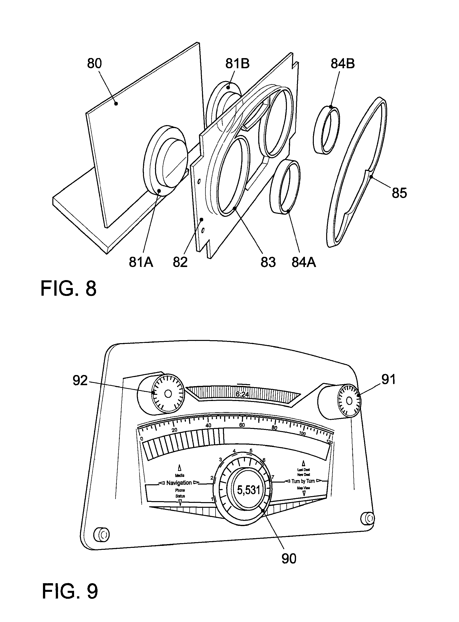
FIG. 8 is an exploded view of a display unit according to an example embodiment of the present invention.
FIG. 9 illustrates a display unit according to an example embodiment of the present invention.
FIG. 10 shows a display unit according to a further example embodiment of the present invention.
FIG. 11 shows a vehicle that includes a display unit according to an example embodiment of the present invention.
DETAILED DESCRIPTION
In the following, example embodiments of the present invention are described in more detail with reference to the Figures. The following description of example embodiments is not to be construed as limiting, but merely as being intended to provide some illustrative examples on how the present invention may be implemented. In particular, implementation is not limited to the example embodiments described hereinafter.
Features of various example embodiments described may be combined with each other unless specifically noted otherwise. On the other hand, describing an example embodiment with a plurality of features is not to be construed as indicating that all those features are necessary, as other example embodiments may include less features and/or alternative features.
Example embodiments described hereinafter may include an electronic display and a light guide. In the present context, an electronic display may show visible features, in particular, visible information such as text, graphics, indicators, etc. in response to electric signals. Electronic displays may include organic light emitting diode (OLED) displays, liquid crystal displays (LCD), or thin-film transistors (TFT) displays, etc.
A light guide generally is a device which guides light from a first location to a second location. Light guides typically use internal reflection, in particular, total internal reflection, caused at interfaces between materials having different refractive indices to guide the light. Conventional light guides include optical fibers, such as silica-based fibers, glass fibers or plastic fibers or so-called light pipes, which include a plurality of, for example, several hundreds to several thousands of individual optical fibers fixed together, for example, fused together. With such light pipes, light guides with a comparatively large diameter may be provided.
FIG. 1 schematically illustrates a display unit for a vehicle according to an example embodiment of the present invention. The display unit of FIG. 1 includes an electronic display 10 for displaying information to a driver. The information may include information such as velocity of the vehicle, fuel level of the vehicle, navigation information, engine speed of the vehicle, map information or also information not directly related to driving, for example, information from the internet or information regarding radio stations.
Coupled with electronic display 10 is a light guide 12, for example, a light pipe, which guides light representing a portion of the information, e.g., the information displayed on electronic display 10 at the location where light pipe 12 is adjacent to electronic display 10, to predetermined locations at a distance d from electronic display 10 for viewing, thus creating a three-dimensional impression. The distance d in the example embodiment illustrated in FIG. 1 is determined by the dimension of light guide 12. Furthermore, a bezel 11 is provided covering portions of electronic display 10 which are not used for displaying information.
It should be noted that bezel 11 need not cover the complete area not covered by light guide 12, but other uncovered areas of electronic display 10 may exist for displaying information besides the information viewable via light guide 12. Various configurations and locations for light guides in display units for vehicles may be used. Some examples for such configurations will next be explained with reference to FIGS. 2A to 2F. The example embodiments of FIGS. 2A to 2F substantially show plan views of display units.
Throughout FIGS. 2A to 2F, 20 designates an electronic display, of which the contour is shown in FIGS. 2A to 2F. Electronic display 20 may be used for displaying various kinds of information to a driver, for example, the velocity of a vehicle, the engine speed of a vehicle, the fuel level of a vehicle, other information related to driving such as a cooling fluid temperature, as well as information not directly related to driving such as information of a tuned radio station, or outside temperature. The information may be displayed in a manner resembling conventional gauges using pointers for velocity or engine speed. For instance, a velocity may be displayed in a left part of electronic display 20, while an engine speed may be displayed in a right part of display 20.
In the example embodiment of FIG. 2A, two light guides 21, 22 each having a circular cross-section are provided, one in the left part of display 20 and one in the right part of display 20. For example, light guide 21 may serve to guide light corresponding to velocity information, and light guide 22 may be arranged to guide light corresponding to engine speed information, just to give an example. In this manner, by providing a three-dimensional appearance via the light guides 21, 22 in the example embodiment illustrated in FIG. 2A corresponding information, for example, velocity information and speed information, is highlighted.
In the example embodiment illustrated in FIG. 2B, two semicircular rings 23, 24 are provided as light guides. Rings 23, 24 may, for example, be provided above portions of display 20 where scale for velocity or engine speed are displayed, or velocity/engine speed may be displayed by gradually filling the area covered by light guides 23, 24.
In the example embodiment illustrated in FIG. 2C, light guides 25, 26 are provided in locations similar to the locations of light guides 21, 22 illustrated in FIG. 2A. Light guide 25 includes an outer portion 25A and an inner portion 25B, and light guide 26 includes an outer portion 26A and an inner portion 26B. The thickness of the respective outer portion 25A, 26A may be different from, for example, smaller than, a thickness of the respective inner portion 25B, 26B. The thickness, in this respect, in the context of FIGS. 2A to 2F is the dimension perpendicular to the surface of display 20. In embodiment embodiments, the respective outer portion 25A, 26A may, for example, cover a scale of a displayed pointer gauge, and the inner portion 25B, 26B may cover a respective inner portion including the pointer of the respective gauge. However, other configurations are possible as well.
In the example embodiment illustrated in FIG. 2D, a light guide 27 is provided in a lower portion of display 20. At this portion of display 20, for example, a fuel level, a temperature and/or a time may be displayed.
In the example embodiment illustrated in FIG. 2E, a light guide 28 is provided in an upper portion of display 20. In the upper portion of display 20, for example, a fuel level, a time and/or a temperature may be displayed.
In the example embodiment illustrated in FIG. 2F, two light guides 29, 210 are provided. Light guide 29 includes an outer portion 29A and an inner portion 29B, and light guide 210 includes an outer portion 210A and an inner portion 210B, somewhat similar to the structure of light guides 25, 26 of the example embodiment illustrated in FIG. 2C. However, in contrast to the example embodiment illustrated in FIG. 2C, outer portion 29A, 210A surround their respective inner portions 29B, 210B only partially, e.g., in a semicircle as illustrated in FIG. 2F. Geometries other than semicircular, example, a quarter-circular, are also possible.
The thickness of outer portion 29A, 210A may be different, for example, smaller than, the thickness of inner portions 29B, 210B.
It should be noted that the example embodiments illustrated in FIGS. 2A to 2F may be combined with each other. For example, light guide 21 illustrated in FIG. 2A and light guide 24 illustrated in FIG. 2B may be provided, or light guide 28 illustrated in FIG. 2E and/or 27 illustrated in FIG. 2D may be provided additionally in the example embodiments illustrated in FIG. 2A, 2B, 2C or 2F.
The visible effect provided by light guides, for example, light pipes, as mentioned in the previous example embodiments is illustrated in FIGS. 3A and 3B. FIG. 3A illustrates a light pipe 30 having a cylindrical shape, which may, for example, correspond to light guide 21 or 22 illustrated in FIG. 2A. As can be seen, the part of the logo covered by light pipe 30 can be seen at a distance from the original printing, e.g., at an end facet of the light pipe.
In FIG. 3B, a light pipe 31 including an outer portion 31A and an inner portion 31B is illustrated. The thickness of the inner portion 31B exceeds the thickness of the outer portion 31A. This has the visible effect, as illustrated in FIG. 3B, that the logo can be viewed in different levels, e.g., different portions can be seen at different distances from the print of the logo (which, in a display unit as discussed with reference to FIG. 1 or FIG. 2, would correspond to the level of the display). Light pipe 31 may, for example, be used as light guide 25, 26 in the example embodiment illustrated in FIG. 2C. Light guides such as light guide 31 illustrated in FIG. 3B may be made by bonding two cylindrical light guides having different diameters together, thus forming a two layer light guide.
Further example embodiments of display units will be described with reference to FIGS. 4A to 4H. FIGS. 4A to 4H each illustrate a side view of a display unit, e.g., a view similar to the view illustrated in FIG. 1 and perpendicular to the views illustrated in FIGS. 2A to 2F. Throughout FIGS. 4A to 4H, an electronic display, in the example embodiment shown a display based on organic light emitting diodes (OLEDs), bears reference numeral 40. In other example embodiments, other kinds of displays such as LCD or TFT displays may be used.
In FIG. 4A, a light guide 42A, for example, a light pipe, having a rectangular cross-section, for example, a cylindrical light pipe as illustrated in FIG. 3A, is provided. A bezel 41A covers at least some portions of display 40 not covered by light guide 42A.
In the example embodiment illustrated in FIG. 4B, a light guide 42B and a bezel 41B are provided. The face opposite display 40 of light guide 42B is rounded as illustrated in FIG. 4B. Depending on these internal structure of the light guide, the visual effect thus achieved is different from the visual effect of a flat surface as illustrated in FIG. 4A. For example, an effect somewhat similar to the effect of a lens may be achieved, thus combining properties of a lens with those of a light guide.
In the example embodiment illustrated in FIG. 4C, a bezel 41C and a light guide 42C are provided. Light guide 42C is somewhat similar to light guide 31 illustrated in FIG. 3B, with slanted faces between outer portion and inner portion.
In FIG. 4D, a bezel 41D and a light guide 42D are provided. Light guide 42D is bent to provide the image around a corner, e.g., the image which represents information may, in FIG. 4D, be seen from the direction indicated by an arrow 44. This allows freedom of design regarding the placement of display 40 relative to an occupant of the vehicle for whom the information displayed on display 40 is intended.
In FIG. 4E, a bezel 41E and a light guide 42E are illustrated. Light guide 42E has a double-bent cross-section as illustrated in FIG. 4E, such that the image generated by display 40 can be seen at a position displaced from its original position in the plane of display 40.
In FIG. 4F, a display unit includes a bezel 41F and a plurality of light guides 42F which all have a rectangular cross-section.
In FIG. 4G, the display unit includes a bezel 41G and light guides 42G having a trapezoidal cross-section. In FIG. 4H, a bezel 41H is provided together with light guides 42H and 43H having different diameters, e.g., dimensions parallel to the plane of display 40, and each having a rounded surface at the face opposite the face adjacent to display 40.
FIGS. 4A to 4H illustrate that a plurality of variations are possible in designing the light guide. It should be noted that the various possibilities illustrated in FIGS. 4A to 4H may be combined. For example, light guide 42E may have a rounded surface like light guide 42B, or any of the straight light guides illustrated may be bent as light guide 42D.
It also should be noted that the various cross-sections illustrated in FIGS. 4A to 4H may be used in any of the example embodiments illustrated in FIGS. 2A to 2F.
It further should be noted that in case light pipes are used as light guides, interstitial material between the individual optical fibers of the light pipe may be selected to achieve desired light carrying properties of the light pipes. For example, by varying the interstitial material perceived contrast and viewing angle of the light pipe may be altered. In FIG. 5, a perspective view of an example embodiment is shown. In the example embodiment illustrated in FIG. 5, a display 50, for example, an OLED display, is covered by a fiber optic glass 51, e.g., a glass manufactured by fusing optical fibers together (e.g., substantially a thin light pipe), which has a cylindrical light pipe 52 formed thereon. In other words, in the example embodiment illustrated in FIG. 5, light pipes 52 and fiber optic glass 51 are substantially formed as a single light pipe, light pipe 52 protruding from the planar fiber optic glass 51. Fiber optic glass 51 is bonded to display 50. It should be noted that instead of a cylindrical shape for light pipe 52, any other shape may be used, for example any of the shapes discussed with reference to FIGS. 1 to 4.
In FIG. 6, a display unit 60 according to an example embodiment incorporated in a cockpit of a car is illustrated. Display unit 60 includes an electronic display for displaying information, parts of which are covered by a bezel 63, other parts of which are covered by light guides 61, 62 and a further part 64 is left free. In the part covered by light guide 61, information such as temperature or engine speed is shown. In a portion covered by light guide 62, information such as current velocity or fuel level is shown. In portion 64, driving assistance information regarding the distance to a preceding vehicle is shown. As can be seen, the parts of display covered by light guides 61, 62, because of the light guiding properties thereof, appear closer to a viewer than the information displayed in portion 64 without a light guide, thus creating a three-dimensional impression.
In FIG. 7, a possibility for manufacturing a display unit such as the one illustrated in FIG. 6 is indicated. An electronic display 70, in the example shown, an OLED display, is provided. Fiber optic light pipes 70, 72 are bonded to display 70 at the desired places. An aluminum plate 73 having lips 75 to surround the light pipes 71, 72 is fastened to display 70, for example, by using mounting holes at the side of aluminum plate 73 to fasten aluminum plate 73 to a support structure which in the vehicle is behind display 70. A bezel which may be made from back ABS plastic bearing reference 74 in FIG. 7 is provided covering portions of display 70 not used for displaying information.
In FIG. 8, the manufacture a different display according to an example embodiment is illustrated. In FIG. 8, a electronic display, for example, an OLED display, is provided. Light guides 81A, 81B which may be light pipes similar to the ones shown in FIG. 3B, e.g., light guides having an outer portion and an inner portion, are bonded to display 80. An aluminum plate 82 is fastened to display 80, aluminum plate 82 having aluminum rings 83 to surround the outer portions of light guides 81A, 81B. Plastic rings, for example, made from black ABS plastic, 84A and 84B are provided to surround the inner portions of light guides 81A and 81B, respectively. A bezel 85, which again may be made from black ABS plastic, is provided.
In FIG. 9, a further example for a display unit usable in a cockpit of a vehicle is illustrated. The display unit of FIG. 9 in particular may be used as a display unit for navigation systems. In the example illustrated in FIG. 9, a light guide 90 having an inner portion and an outer portion similar to light guide 31 illustrated in FIG. 3B and two cylindrical light guides 91, 92 are provided to give a three-dimensional appearance. Apart from the light guides, also portions of the display without light guides are used for displaying information.
In FIG. 10, a further example embodiment of a display unit usable in a cockpit of a car is illustrated. The display unit illustrated in FIG. 10 includes one larger diameter light guide 102 and two smaller diameters light guides 101, 100, all light guides having a substantially cylindrical shape. In the area of the display covered by light guide 102, velocity information and navigation information is displayed, while in the area covered by light guides 100, 101, for example, battery information may be displayed. Other portions of the display provide information without having a light guide superposed.
Display units as discussed above may be used in vehicles, for example, cars. For example, in FIG. 11, a vehicle 110 is illustrated in which a display unit 111 is provided as an instrument panel for a driver. Display unit 111 may be designed as discussed with respect to any of the example embodiments described with reference to FIGS. 1 to 10. It should be noted that display units as discussed herein may not only be used in cars, but also in other motor-driven vehicles, as in practically all kinds of motor driven vehicles, such as, motorcycles, ships or planes, instrument panels are needed to provide information to a driver of the vehicle.
While in some instances, specific materials have been used in the description, such as aluminum or ABS plastic, other materials, for example, other metals or other plastics, may be used as well.
As already emphasized, the above described example embodiments serve only as illustrative examples, and the scope hereof is not limited to these embodiments.
LIST OF REFERENCE NUMERALS
10 display 11 bezel 12 light guide 20 display 21-29;210 light guides 25A, 26A,29A, 210A outer portion 25B, 26B, 29B, 210B inner portion 30 light guide 31 light guide 31A outer portion 31B inner portion 40 display 41A-41H bezel 42A-42H light guide 44 arrow 43 light guide 50 display 51 fiber optic glass 52 light guide 60 display unit 61, 62 light guides 63 bezel 64 free area 70 display 71, 72 light guides 73 aluminum plate 74 bezel 75 aluminum rings 80 display 81A, 81B light guides 82 aluminum plate 83 aluminum rings 84A, 84B plastic rings 85 bezel 90, 91, 92 light guides 100, 101, 102 light guides 110 car 111 display unit
* * * * *
D00000
D00001
D00002
D00003
D00004
D00005
D00006
XML
uspto.report is an independent third-party trademark research tool that is not affiliated, endorsed, or sponsored by the United States Patent and Trademark Office (USPTO) or any other governmental organization. The information provided by uspto.report is based on publicly available data at the time of writing and is intended for informational purposes only.
While we strive to provide accurate and up-to-date information, we do not guarantee the accuracy, completeness, reliability, or suitability of the information displayed on this site. The use of this site is at your own risk. Any reliance you place on such information is therefore strictly at your own risk.
All official trademark data, including owner information, should be verified by visiting the official USPTO website at www.uspto.gov. This site is not intended to replace professional legal advice and should not be used as a substitute for consulting with a legal professional who is knowledgeable about trademark law.