Microscopic three-dimensional measurement system and method based on moving diaphragm
Jiang , et al.
U.S. patent number 10,362,215 [Application Number 15/893,692] was granted by the patent office on 2019-07-23 for microscopic three-dimensional measurement system and method based on moving diaphragm. This patent grant is currently assigned to Ningbo University. The grantee listed for this patent is Ningbo University. Invention is credited to Shengli Fan, Gangyi Jiang, Yigang Wang, Mei Yu.


View All Diagrams
| United States Patent | 10,362,215 |
| Jiang , et al. | July 23, 2019 |
Microscopic three-dimensional measurement system and method based on moving diaphragm
Abstract
The present invention discloses a microscopic three-dimensional measurement system and method based on a moving diaphragm. The present invention adds the diaphragm into the existing optical microscopic imaging system to limit light irradiation angle during imaging for reducing the diameter of blur circle, which extends the depth of field and the depth measurement range, so as to achieve the three-dimensional measurement of large-size objects to be measured. Through changing the position of the added diaphragm, two images with different light incident directions are obtained, which is similar to binocular stereo vision, and then the disparity map is used to predict the depth, so as to carry out the 3D scene reconstruction. Since the depth of field of the imaging system is enlarged and the imaging model has certain non-linear characteristics, the present invention uses quadratic function to express the non-linearity, which reduces the measurement error.
| Inventors: | Jiang; Gangyi (Zhejiang, CN), Yu; Mei (Zhejiang, CN), Fan; Shengli (Zhejiang, CN), Wang; Yigang (Zhejiang, CN) | ||||||||||
|---|---|---|---|---|---|---|---|---|---|---|---|
| Applicant: |
|
||||||||||
| Assignee: | Ningbo University (Ningbo,
Zhejiang, CN) |
||||||||||
| Family ID: | 62092885 | ||||||||||
| Appl. No.: | 15/893,692 | ||||||||||
| Filed: | February 12, 2018 |
Prior Publication Data
| Document Identifier | Publication Date | |
|---|---|---|
| US 20180198972 A1 | Jul 12, 2018 | |
Foreign Application Priority Data
| Nov 17, 2017 [CN] | 2017 1 1144614 | |||
| Current U.S. Class: | 1/1 |
| Current CPC Class: | G02B 21/0016 (20130101); H04N 5/238 (20130101); H04N 5/2354 (20130101); H04N 5/23212 (20130101); H04N 13/239 (20180501); G02B 21/362 (20130101); H04N 13/246 (20180501); H04N 13/271 (20180501); G02B 21/26 (20130101); H04N 5/23216 (20130101); H04N 13/275 (20180501); G06T 7/593 (20170101); G06T 2200/08 (20130101); H04N 2013/0081 (20130101); G06T 2207/10056 (20130101) |
| Current International Class: | G02B 21/22 (20060101); G02B 21/00 (20060101); H04N 13/275 (20180101); H04N 13/271 (20180101); H04N 5/232 (20060101); H04N 13/246 (20180101); G06T 7/593 (20170101); H04N 5/235 (20060101); H04N 5/238 (20060101); G02B 21/36 (20060101); G02B 21/26 (20060101); H04N 13/239 (20180101); H04N 13/00 (20180101) |
References Cited [Referenced By]
U.S. Patent Documents
| 2004/0264764 | December 2004 | Kochi |
| 2007/0222979 | September 2007 | Van Der Laan |
| 2009/0078888 | March 2009 | Namba |
| 2017/0199365 | July 2017 | Czaniera |
Claims
What is claimed is:
1. A microscopic three-dimensional measurement system based on a moving diaphragm comprising: an optical microscope, a camera installed on the optical microscope aligned with an eyepiece of the optical microscope, a lifting platform for horizontally placing a dot calibration board, and a computer, wherein the optical microscope is disposed above the dot calibration board for allowing the eyepiece of the optical microscope to just face towards the dot calibration board, an output end of the camera is connected with the computer, a drive motor of the lifting platform is connected with the computer; a diaphragm, which is able to horizontally move, is disposed between the eyepiece of the optical microscope and the dot calibration board; an optical axis of the optical microscope coincides with a moving trajectory of the lifting platform, is perpendicular to both the dot calibration board and a moving trajectory of the diaphragm.
2. The microscopic three-dimensional measurement system, as recited in claim 1, further comprising a sliding base for driving the diaphragm to horizontally move, wherein a drive motor of the sliding base is connected with the computer.
3. A microscopic three-dimensional measurement method with a microscopic three-dimensional measurement system based on a moving diaphragm, wherein: the microscopic three-dimensional measurement system comprises an optical microscope, a camera installed on the optical microscope aligned with an eyepiece of the optical microscope, a lifting platform for horizontally placing a dot calibration board, and a computer, wherein the optical microscope is disposed above the dot calibration board for allowing the eyepiece of the optical microscope to just face towards the dot calibration board, an output end of the camera is connected with the computer, a drive motor of the lifting platform is connected with the computer; the moving diaphragm, which is able to horizontally move, is disposed between the eyepiece of the optical microscope and the dot calibration board; the method comprises steps of: (1) coinciding an optical axis of the optical microscope with a moving trajectory of the lifting platform; horizontally placing the dot calibration board on a top surface of the lifting platform and allowing the dot calibration board to be perpendicular to the optical axis of the optical microscope; allowing a moving trajectory of the diaphragm installed on a sliding base to be perpendicular to the optical axis of the optical microscope; placing the diaphragm between the eyepiece of the optical microscope and the dot calibration board, wherein a center distance between two adjacent solid dots in the dot calibration board is defined as e, a diameter of every solid dot in the dot calibration board is defined as d, d<e, a unit of both the d and the e is mm, a diameter of an aperture of the diaphragm is defined as D, D.di-elect cons.[1,5], and a unit of the D is mm; (2) determining an initial position of the aperture of the diaphragm, which comprises positioning a center of the aperture of the diaphragm on the optical axis of the optical microscope through controlling the sliding base; moving the diaphragm left horizontally for a distance L through controlling the sliding base, which means that a distance between the center of the aperture of the diaphragm and the optical axis of the optical microscope is L; determining a current position of the center of the aperture of the diaphragm to be the initial position of the aperture of the diaphragm and recording as T.sub.L, wherein L .di-elect cons.[2,4], and a unit of the L is mm; determining an initial position of the dot calibration board, which comprises controlling the lifting platform to drive the dot calibration board to move vertically and stopping the vertical movement of the lifting platform when a dot calibration board image observed by an observer from the computer is the clearest; controlling the lifting platform to drive the dot calibration board to move vertically and upwardly, stopping the vertical and upward movement of the lifting platform when the dot calibration board image observed by the observer from the computer changes from the clearest to just fuzzy, recording a current vertical upward moving distance of the lifting platform as Z.sub.s, determining a current position of the dot calibration board to be the initial position of the dot calibration board and recording as P.sub.0, wherein a unit of the Z.sub.s is mm; (3) when the dot calibration board is at the initial position P.sub.0, respectively placing four tiny markers at four solid dots on the dot calibration board; making a shape, formed by taking centers of the four solid dots where the four tiny markers are as vertexes, always a rectangle; the observer observing the dot calibration board image displayed by the computer; moving the four tiny markers; displaying the rectangle, which is defined by taking centers of the four solid dots where the four tiny markers are as vertexes, in the dot calibration board image with a largest area and recording as A'; (4) controlling the sliding base to move the diaphragm right horizontally for a distance of 2L and recording a current position of the aperture of the diaphragm as T.sub.R; and then the observer observing the dot calibration board image displayed by the computer; moving the four tiny markers; displaying the rectangle, which is defined by taking the centers of the four solid dots where the four tiny markers are as vertexes, in the dot calibration board image with a largest area and recording as A, saving a current dot calibration board image and recording as S.sub.0,T.sub.R; and then controlling the sliding base to move the diaphragm left horizontally for a distance of 2L, positioning the aperture of the diaphragm at a position of T.sub.L, saving a current dot calibration board image and recording as S.sub.0,T.sub.L, wherein: the A is included in the A', an amount of columns of solid dots in a width direction of the A on the dot calibration board is defined as W, and an amount of rows of solid dots in a height direction of the A on the dot calibration board is defined as H, which means that there are totally W.times.H solid dots of the A on the dot calibration board, both the W and the H are positive integers; (5) taking a top left corner vertex of the A on the dot calibration board as a coordinate origin O, defining an X positive axis by a direction which points at centers of solid dots at a same row, defining a Y positive axis by a direction which points to centers of solid dots at a same column, defining a vertically downwardly moving direction of the lifting platform as a Z positive axis, so as to establish a three-dimensional coordinate system OXYZ; respectively performing binary processing on the S.sub.0,T.sub.L and the S.sub.0,T.sub.R, obtaining binary images respectively corresponding to the S.sub.0,T.sub.L and the S.sub.0,T.sub.R; processing the binary images of the S.sub.0,T.sub.L through a region growing algorithm, obtaining both every solid dot region and multiple candidate coordinate positions of a center of the every solid dot region in the S.sub.0,T.sub.L; similarly, processing the binary images of the S.sub.0,T.sub.R through the region growing algorithm, obtaining both every solid dot region and multiple candidate coordinate positions of a center of the every solid dot region in the S.sub.0,T.sub.R; and then determining any one of the multiple candidate coordinate positions of the center of the every solid dot region within a rectangle area in the S.sub.0,T.sub.L corresponding to the A, to a final coordinate position of the center of the solid dot region; recording a final coordinate position of a center of a i .sup.th column and j .sup.th row solid dot region within the rectangle area in the S.sub.0,T.sub.L corresponding to the A as; (U.sub.l,i,j,0,v.sub.l,i,j,0); similarly, determining any one of the multiple candidate coordinate positions of the center of the every solid dot region within a rectangle area in the S.sub.0,T.sub.R corresponding to the A, to a final coordinate position of the center of the solid dot region; recording a final coordinate position of a center of a i.sup.th column and j.sup.th row solid dot region within the rectangle area in the S.sub.0,T.sub.R corresponding to the A as (U.sub.r,i,j,0,v.sub.r,i,j,0), wherein: both the i and the j are positive integers, 1.ltoreq.i.ltoreq.W, 1.ltoreq.j.ltoreq.H; (6) controlling the lifting platform to drive dot calibration board to move vertically and downwardly for a distance of .DELTA..alpha., recording a current position of the dot calibration board as P.sub.1, recording a current dot calibration board image and recording as S.sub.1,T.sub.L; and then controlling the lifting platform to move right horizontally the diaphragm for a distance of 2L, positioning the aperture of the diaphragm at a position of T.sub.R, saving a current dot calibration board image and recording as S.sub.1,T.sub.R; and then controlling the lifting platform to move left horizontally the diaphragm for a distance of 2L, positioning the aperture of the diaphragm at a position of T.sub.L, wherein .DELTA..alpha..di-elect cons.(Z.sub.s/100, Z.sub.s/50), a unit of the .DELTA..alpha. is mm; (7) respectively performing binary processing on the S.sub.1,T.sub.L and the S.sub.1,T.sub.R, obtaining binary images respectively corresponding to the S.sub.1,T.sub.L and the S.sub.1,T.sub.R; processing the binary images of the S.sub.1,T.sub.L through the region growing algorithm, obtaining both every solid dot region and multiple candidate coordinate positions of a center of the every solid dot region in the S.sub.1,T.sub.L; similarly, processing the binary images of the S.sub.1,T.sub.R through the region growing algorithm, obtaining both every solid dot region and multiple candidate coordinate positions of a center of the every solid dot region in the S.sub.1,T.sub.R; and then according to the multiple candidate coordinate positions of the center of the every solid dot region within a rectangle area in the S.sub.1,T.sub.L corresponding to the A, determining a final coordinate position of the center of the every solid dot region within the rectangle area in the S.sub.1,T.sub.L corresponding to the A; recording a final coordinate position of a center of a i.sup.th column and j.sup.th row solid dot region within the rectangle area in the S.sub.1,T.sub.L corresponding to the A as (u.sub.l,i,j,1,v.sub.l,i,j,1), wherein the (u.sub.l,i,j,1,v.sub.l,i,j,1) is a candidate coordinate position with a smallest Euclidean distance to the (u.sub.l,i,j,0,v.sub.l,i,j,0) in the multiple candidate coordinate positions of the center of the i.sup.th column and j.sup.th row solid dot region within the rectangle area in the S.sub.1,T.sub.L corresponding to the A; similarly, according to the multiple candidate coordinate positions of the center of the every solid dot region within a rectangle area in the S.sub.1,T.sub.R corresponding to the A, determining a final coordinate position of the center of the every solid dot region within the rectangle area in the S.sub.1,T.sub.R corresponding to the A; recording a final coordinate position of a center of a i .sup.th column and j.sup.th row solid dot region within the rectangle area in the S.sub.1,T.sub.R corresponding to the A as (u.sub.r,i,j,1,v.sub.r,i,j,1), wherein the (u.sub.r,i,j,1,v.sub.r,i,j,1) is a candidate coordinate position with a smallest Euclidean distance to the (u.sub.r,i,j,0,v.sub.r,i,j,0) in the multiple candidate coordinate positions of the center of the i.sup.th column and j.sup.th row solid dot region within the rectangle area in the S.sub.1,T.sub.R corresponding to the A; calculating three-dimensional coordinates on the three-dimensional coordinate system OXYZ of a center of every solid dot within the A on the dot calibration board after the lifting platform driving the dot calibration board to firstly move vertically and downwardly for a distance of .DELTA..alpha., recording three-dimensional coordinates on the three-dimensional coordinate system OXYZ of a center of a i.sup.th column and j.sup.th row solid dot within the A on the dot calibration board after the lifting platform driving the dot calibration board to firstly move vertically and downwardly for the distance of .DELTA..alpha.as (x.sub.i,j,1,y.sub.i,j,1z.sub.i,j,1), wherein x.sub.i,j,1=(i-1).times.e, y.sub.i,j,1=(j-1).times.e and z.sub.i,j,1=1.times..DELTA..alpha.; and then calculating a multi-aperture imaging bias corresponding to every solid dot within the A on the dot calibration board after the lifting platform driving the dot calibration board to firstly move vertically and downwardly for the distance of .DELTA..alpha., recording a multi-aperture imaging bias corresponding to a i.sup.th column and j.sup.th row solid dot within the A on the dot calibration board after the lifting platform driving the dot calibration board to firstly move vertically and downwardly for the distance of .DELTA..alpha. as .DELTA.u.sub.i,j,1, here, .DELTA.u.sub.i,j,1=u.sub.l,i,j,1-u.sub.r,i,j,1, wherein x.sub.i,j,1,y.sub.i,j,1,z.sub.i,j,1 respectively represent an X-axis coordinate, a Y-axis coordinate and a Z-axis coordinate on the three-dimensional coordinate system OXYZ of the center of the i.sup.th column and j.sup.th row solid dot within the A on the dot calibration board after the lifting platform driving the dot calibration board to firstly move vertically and downwardly for the distance of .DELTA..alpha.; (8) repeating the steps (6) and (7) for (N-1) times, recording a current position of the dot calibration board as P.sub.k after the lifting platform drives the dot calibration board to move downwardly and vertically for .DELTA..alpha. at a k.sup.th time, recording a current dot calibration board image as S.sub.k,T.sub.L; recording a dot calibration board image as S.sub.k,T.sub.R after moving right horizontally the diaphragm for 2L; recording a final coordinate positions of a center of a i.sup.th column and j.sup.th row solid dot region within a rectangle area in the S.sub.k,T.sub.L corresponding to the A as (u.sub.l,i,j,k,V.sub.l,i,j,k), wherein the (u.sub.l,i,j,k,V.sub.l,i,j,k) is a candidate coordinate position with a smallest Euclidean distance to the ((u.sub.l,i,j,k-1,V.sub.l,i,j,k-1) in multiple candidate coordinate positions of the center of the i.sup.th column and j.sup.th row solid dot region within the rectangle area in the S.sub.k,T.sub.R corresponding to the A; recording a final coordinate positions of a center of a i.sup.th column and j.sup.th row solid dot region within a rectangle area in the S.sub.k,T.sub.R corresponding to the A as (u.sub.r,i,j,k,v.sub.r,i,j,k), wherein the (u.sub.r,i,j,k,v.sub.r,i,j,k) is a candidate coordinate position with a smallest Euclidean distance to the (u.sub.r,i,j,k-1,v.sub.r,i,j,k-1) in multiple candidate coordinate positions of the center of the i.sup.th column and j.sup.th row solid dot region within the rectangle area in the S.sub.k,T.sub.R corresponding to the A; recording three-dimensional coordinates on the three-dimensional coordinate system OXYZ of a center of a i.sup.th column and j.sup.th row solid dot within the A on the dot calibration board after the lifting platform driving the dot calibration board to move vertically and downwardly at the k.sup.th time for the distance of .DELTA..alpha. as (x.sub.i,j,k , y.sub.i,j,kz.sub.i,j,k), wherein x.sub.i,j,k=(i-1).times.e, y.sub.i,j,k=(j-1).times.e and z.sub.i,j,k=k.times..DELTA..alpha.; and then recording a multi-aperture imaging bias corresponding to a i.sup.th column and j.sup.th row solid dot within the A on the dot calibration board after the lifting platform driving the dot calibration board to move vertically and downwardly at the k.sup.th time for the distance of .DELTA..alpha. as .DELTA.u.sub.i,j,k, here, .DELTA.u.sub.i,j,k=u.sub.l,i,j,k-u.sub.r,i,j,k, wherein N is a positive integer, .times..DELTA..alpha. ##EQU00017## ".left brkt-bot. .right brkt-bot." represents a round downward operator, k is a positive integer, 1.ltoreq.k.ltoreq.N, X.sub.i,j,k, y.sub.i,j,k, z.sub.i,j,k respectively represent an X-axis coordinate, a Y-axis coordinate and a Z-axis coordinate on the three-dimensional coordinate system OXYZ of the center of the i.sup.th column and j.sup.th row solid dot within the A on the dot calibration board after the lifting platform driving the dot calibration board to move vertically and downwardly at the k.sup.th time for the distance of .DELTA..alpha.; (9) forming a data pair by combining the Z-axis coordinate on the three-dimensional coordinate system OXYZ of the center of every solid dot within the A on the dot calibration board after the lifting platform driving the dot calibration board to move vertically and downwardly every time for the distance of .DELTA..alpha., with a corresponding multi-aperture imaging bias, recording the data pair formed by the z.sub.i,j,k and the .DELTA.u.sub.i,j,k as (z.sub.i,j,k, .DELTA.u.sub.i,j,k,); and then through a quadratic polynomial, fitting N data pairs corresponding to every solid dot within the A on the dot calibration board, obtaining a relationship between the Z-axis coordinate on the three-dimensional coordinate system of the center of every solid dot within the A on the dot calibration board and a corresponding multi-aperture imaging bias, defining a relationship between the Z-axis coordinate z.sub.i,j on the three-dimensional coordinate system of the center of the i.sup.th column and j.sup.th row solid dot within the A on the dot calibration board and a corresponding multi-aperture imaging bias .DELTA.u.sub.i,j as z.sub.i,j=a.sub.i,j.DELTA.u.sub.i,j.sup.2+b.sub.i,j,.DELTA.u.sub.i,j+c.su- b.i,j, wherein all of the a.sub.i,j, the b.sub.i,j and the c.sub.i,j are coefficients obtained by fitting, there are totally (W.times.H) coefficients; calculating a corresponding focal plane moving distance of every solid dot within the A on the dot calibration board after the lifting platform drives the dot calibration board to move downwardly and vertically every time for a distance of .DELTA..alpha., recording a corresponding focal plane moving distance of the i.sup.th column and j.sup.th row solid dot within the A on the dot calibration board as .DELTA.z.sub.i,j,k after the lifting platform drives the dot calibration board to move vertically and downwardly at the k.sup.th time for the distance of .DELTA..alpha., here, .DELTA.z.sub.i,j,k=z.sub.i,j,k-c.sub.i,j; and then forming a data pair by
combining a corresponding focal plane moving distance of every solid dot within the A on the dot calibration board after the lifting platform drives the dot calibration board to move vertically and downwardly every time for the distance of .DELTA..alpha., with a corresponding multi-aperture imaging bias, recording the data pair formed by the .DELTA.z.sub.i,j,k and .DELTA.u.sub.i,j,k as (.DELTA.z.sub.i,j,k,.DELTA.u.sub.i,j,k); and then through a quadratic polynomial, fitting N.times.W.times.H data pairs corresponding to all solid dots within the A on the dot calibration board, obtaining a relationship between a focal plane moving distance .DELTA.z corresponding to any point on the dot calibration board and a corresponding multi-aperture imaging bias .DELTA.u, defining the relationship as .DELTA.z=.alpha..DELTA.u.sup.2+b.DELTA.u+c, wherein all of the a, the b and the c are coefficients obtained by fitting; according to the X-axis coordinate and the Y-axis coordinate on the three-dimensional coordinate system OXYZ of the center of every solid dot within the A on the dot calibration board after the lifting platform firstly drives the dot calibration board to move vertically and downwardly for the distance of .DELTA..alpha., determining (W.times.H) three-dimensional scattered points and three-dimensional coordinates of an i.sup.th column and j.sup.th row three-dimensional scattered point to (X.sub.i,j,1,y.sub.i,j,1,c.sub.i,j); and then through a plane fitting method, plane-fitting the (W.times.H) three-dimensional scattered points, obtaining a space plane with an equation of z=b.sub.1+b.sub.2x+b.sub.3y, here, all of the b.sub.1, the b.sub.2 and the b.sub.3are coefficients obtained by fitting, (x,y,z) presents three-dimensional coordinates of space points in the three-dimensional coordinate system OXYZ, the x,y,z respectively represent an X-axis coordinate, a Y-axis coordinate and a Z-axis coordinate of every space point in the three-dimensional coordinate system OXYZ; (10) determining a relationship, between corresponding coordinate positions (u,v) of any obtained point in the dot calibration board images and on the dot calibration board when the aperture of the diaphragm is at a position of T.sub.L after the lifting platform drives the dot calibration board move vertically and downwardly every time for the distance of .DELTA..alpha., and a corresponding focal plane moving distance .DELTA.z of the point on the dot calibration board, defining the relationship between the (u, v) and the .DELTA.z as .times..DELTA..times..times..times..DELTA..times..times..times..DELTA..ti- mes..times..times..DELTA..times..times. ##EQU00018## here 1.ltoreq.u.ltoreq.W',1.ltoreq.v.ltoreq.H', W' represents a width of an obtained dot calibration board image when the aperture of the diaphragm is at a position of T.sub.L after the lifting platform drives the dot calibration board move vertically and downwardly every time for the distance of .DELTA..alpha., H' represents a height thereof, all of the a.sub.f, b.sub.f, d.sub.f, a.sub.g, b.sub.g and d.sub.g are quadratic polynomial coefficients; forming a data pair by combining an X-coordinate of a final coordinate position of a center of every solid dot region within a rectangle area corresponding to the A in the obtained dot calibration board image after the lifting platform drives the dot calibration board to move vertically and downwardly every time for the distance of .DELTA..alpha., with a corresponding focal plane moving distance of every solid dot within the A on the dot calibration board, recording the data pair formed by u.sub.l,i,j,k and .DELTA.z.sub.i,j,k as (u.sub.l,i,j,k,.DELTA.z.sub.i,j,k and then through a quadratic polynomial, fitting N data pairs corresponding to every solid dot of both every solid dot region within a rectangle area corresponding to the A in the dot calibration board image and within the A on the dot calibration board, obtaining a relationship between an X-coordinate of a final coordinate position of a center of every solid region within a rectangle area corresponding to the A in the dot calibration board image, and a corresponding focal plane moving distance of every solid dot within the A on the dot calibration board; defining a relationship between an X-coordinate u.sub.l,i,j of a final coordinate position of a center of an i.sup.th column and j.sup.th row solid region within the rectangle area corresponding to the A in the dot calibration board image, and a corresponding focal plane moving distance .DELTA.z.sub.i,j of the i.sup.th column and j.sup.th row solid dot within the A on the dot calibration board as u.sub.l,i,j=a.sub.f,i,j.times..DELTA.z.sub.i,j.sup.2+b.sub.f,i,j.times..D- ELTA.z.sub.i,j+d.sub.f,i,j, here, all of the a.sub.f,i,jb.sub.f,i,j and d.sub.f,i,j are coefficients obtained by fitting, there are totally (W.times.H) coefficients; forming a data pair by combining a Y-coordinate of the final coordinate position of the center of every solid dot region within the rectangle area corresponding to the A in the obtained dot calibration board image after the lifting platform drives the dot calibration board to move vertically and downwardly every time for the distance of .DELTA..alpha., with the corresponding focal plane moving distance of every solid dot within the A on the dot calibration board, recording the data pair formed by v.sub.l,i,j,k and .DELTA.z.sub.i,j,k as (v.sub.l,i,j,k,.DELTA.z.sub.i,j,k); and then through the quadratic polynomial, fitting N data pairs corresponding to every solid dot of both every solid dot region within the rectangle area corresponding to the A in the dot calibration board image and within the A on the dot calibration board, obtaining a relationship between a Y-coordinate of the final coordinate position of the center of every solid region within the rectangle area corresponding to the A in the dot calibration board image, and the corresponding focal plane moving distance of every solid dot within the A on the dot calibration board; defining a relationship between a Y-coordinate V.sub.l,i,j of the final coordinate position of the center of the i.sup.th column and j.sup.th row solid region within the rectangle area corresponding to the A in the dot calibration board image, and the corresponding focal plane moving distance .DELTA.z.sub.i,j of the i.sup.th column and j.sup.th row solid dot within the A on the dot calibration board as v.sub.l,i,j=a.sub.g,i,j.times..DELTA.z.sub.i,j.sup.2+b.sub.g,i,j.times..D- ELTA.z.sub.i,j+d.sub.g,i,j, here, all of the a.sub.g,i,j, b.sub.g,i,j and d.sub.g,i,j are coefficients obtained by fitting, there are totally (W.times.H) coefficients, wherein a.sub.f,i,j and b.sub.f,i,j form a data pair to obtain (W.times.H) data pairs; and then the (W.times.H) data pairs are linearly fitted, a relationship between a quadratic polynomial a.sub.f and a quadratic polynomial coefficient b.sub.f is obtained, the relationship is defined as a.sub.f=k.sub.f,a.times.b.sub.f+c.sub.f,a, here, both k.sub.f,a and c.sub.f,a are coefficients obtained by fitting; wherein d.sub.f,i,j and b.sub.f,i,j form a data pair to obtain (W.times.H) data pairs; and then the (W.times.H) data pairs are linearly fitted, a relationship between a quadratic polynomial coefficient d.sub.f and a quadratic polynomial coefficient b.sub.f is obtained, the relationship is defined as d.sub.f=k.sub.f,d.times.b.sub.f+c.sub.f,d here, both k.sub.f,d and c.sub.f,d are coefficients obtained by fitting; wherein a.sub.g,i,j and b.sub.g,i,j form a data pair to obtain (W.times.H) data pairs; and then the (W.times.H) data pairs are linearly fitted, a relationship between a quadratic polynomial coefficient a.sub.g and a quadratic polynomial coefficient b.sub.g is obtained, the relationship is defined as a.sub.g=k.sub.g,a.times.b.sub.g+c.sub.g,a, here, both k.sub.g,a and c.sub.g,a are coefficients obtained by fitting; wherein d.sub.g,i,j and b.sub.g,i,j form a data pair to obtain (W.times.H) data pairs; and then the (W.times.H) data pairs are linearly fitted, a relationship between a quadratic polynomial coefficient d.sub.g and a quadratic polynomial coefficient b.sub.g is obtained, the relationship is defined as d.sub.g=k.sub.g,d.times.b.sub.g+c.sub.g,d, here, both k.sub.g,d and c.sub.g,d are coefficients obtained by fitting; defining .times..times. ##EQU00019## ##EQU00019.2## and then defining M=BC.sup.-1; (11) placing the object to be measured on a top surface of the lifting platform, making the object to be measured perpendicular to the optical axis of the optical microscope; and then positioning the aperture of the diaphragm at the position of T.sub.L through controlling the sliding base, saving a current image of the object to be measured and taking as a first image; and then controlling the sliding base to move the diaphragm right horizontally for the distance of 2.sub.L, positioning the aperture of the diaphragm at the position of T.sub.R, saving a current image of the object to be measured and taking as a second image; and then through a stereo matching algorithm, three-dimensionally matching the first image with the second image, obtaining a disparity map between the first image and the second image, recording the disparity map as I.sub.d, wherein a size of all the first image, the second image and the I.sub.d is M.sub.d.times.N.sub.d; (12) defining .DELTA.u=G(x.sub.d,y.sub.d), wherein .DELTA.z.sub.d represents a corresponding focal plane moving distance of the I.sub.d.DELTA.z.sub.d=a.DELTA.u.sup.2+b.DELTA.u+c; optaining a value of .DELTA.z.sub.d based on the .DELTA.u =G(x.sub.d,y.sub.d) and the .DELTA.z.sub.d=a.DELTA.u.sup.2+b.DELTA.u+c, wherein G(x.sub.d,y.sub.d) represent gray values of a pixel point with coordinate positions of (x.sub.d,y.sub.d) in the I.sub.d, 1.ltoreq.x.sub.d.ltoreq.M.sub.d,1.ltoreq.y.sub.d.ltoreq.N.sub.d; based on a.sub.f=k.sub.f,a.times.b.sub.f+c.sub.f,a, d.sub.f=k.sub.f,d.times.b.sub.f+c.sub.f,d, a.sub.g=k.sub.g,a.times.b.sub.g+c.sub.g,a, a.sub.g=k.sub.g,a.times.b.sub.g+c.sub.g,a and .times..DELTA..times..times..times..DELTA..times..times..times..DELTA..ti- mes..times..times..DELTA..times..times. ##EQU00020## obtaining .times..DELTA..times..times..times..DELTA..times..times..DELTA..times..ti- mes..times..DELTA..times..times..times..DELTA..times..times..DELTA..times.- .times. ##EQU00021## based on u=x.sub.d, v=y.sub.d, .DELTA.z=.DELTA.z.sub.d, the .times..DELTA..times..times..times..DELTA..times..times..DELTA..times..ti- mes..times..DELTA..times..times..times..DELTA..times..times..DELTA..times.- .times. ##EQU00022## obtaining values of b.sub.f and b.sub.g, and respectively recording as b.sub.f(x.sub.d,y.sub.d) and b.sub.g(x.sub.d,y.sub.d); calculating .function..function..function..function..function. ##EQU00023## obtaining coordinate values x(x.sub.d,y.sub.d) of x and coordinate values y(x.sub.d,y.sub.d) of y, wherein M.sup.-1 is an inverse array of M; based on x=x(x.sub.d,y.sub.d) ,Y=y(x.sub.d,y.sub.d) and z=b.sub.1+b.sub.2x+b.sub.3y, obtaining an intermediate value of z and recording as z.sub.0; and then calculating coordinate values of the z, recording as z(x.sub.d,y.sub.d), wherein z(x.sub.d,y.sub.d=z.sub.0-.DELTA.z.sub.d; taking (x(x.sub.d,y.sub.d),y(x.sub.d,y.sub.d),z(x.sub.d,y.sub.d)) as three-dimensional coordinates of a reconstructed space point; and (13) reconstructing three-dimensional coordinates of all space points using all pixel points in the I.sub.d based on the step (12), and obtaining a three-dimensional reconstruction map.
Description
CROSS REFERENCE OF RELATED APPLICATION
The present invention claims priority under 35 U.S.C. 119(a-d) to CN 201711144614.7, filed Nov. 17, 2017.
BACKGROUND OF THE PRESENT INVENTION
Field of Invention
The present invention relates to a microscopic three-dimensional measurement technology, and more particularly to a microscopic three-dimensional measurement system and method based on a moving diaphragm.
Description of Related Arts
The optical microscope is a commonly used three-dimensional micro-measuring instrument, which is used to measure three-dimensional coordinates of space points and obtain experimental data in biomedicine, quality inspection and industrial micromanipulation, for facilitating quantitative analysis, so as to improve the product quality, improve the manufacturing process and ensure the accuracy of scientific research.
Currently, digital stereomicroscopes are often used to achieve microscopic three-dimensional measurements. The computer acquires left and right images taken by a digital stereomicroscope and performs the parameter calibration, stereo matching and three-dimensional reconstruction using existing stereoscopic vision measurement methods, so as to finally achieve the purpose of three-dimensional measurement.
However, the optical microscope has disadvantages of small field of view, severe defocused phenomenon and shallow depth of field. Therefore, if the size of the three-dimensional object to be observed exceeds the shallow depth of field of the optical microscope, the clear left images and the clear right images of the three-dimensional object to be observed are difficult to be obtained, which eventually leads that the three-dimensional measurement cannot be achieved.
SUMMARY OF THE PRESENT INVENTION
A technical problem to be solved provided by the present invention is to provide a microscopic three-dimensional measurement system and method based on a moving diaphragm, both of which utilize the diaphragm to extend the depth of field and the depth measurement range, so as to achieve the three-dimensional measurement of large-size objects to be measured.
Technical solutions adopted by the present invention to solve the above technical problems are as follows.
A microscopic three-dimensional measurement system based on a moving diaphragm comprises: an optical microscope, a camera installed on the optical microscope aligned with an eyepiece of the optical microscope, a lifting platform for horizontally placing a dot calibration board, and a computer, wherein the optical microscope is disposed above the dot calibration board for allowing the eyepiece of the optical microscope to just face towards the dot calibration board, an output end of the camera is connected with the computer, a drive motor of the lifting platform is connected with the computer; a diaphragm, which is able to horizontally move, is disposed between the eyepiece of the optical microscope and the dot calibration board; an optical axis of the optical microscope coincides with a moving trajectory of the lifting platform, is perpendicular to both the dot calibration board and a moving trajectory of the diaphragm.
Preferably, the microscopic three-dimensional measurement system further comprises a sliding base for driving the diaphragm to horizontally move, wherein a drive motor of the sliding base is connected with the computer.
Also, the present invention provides a microscopic three-dimensional measurement method based on a moving diaphragm, which comprises steps of:
(1) coinciding an optical axis of an optical microscope with a moving trajectory of a lifting platform; horizontally placing a dot calibration board on a top surface of the lifting platform and allowing the dot calibration board to be perpendicular to the optical axis of the optical microscope; allowing a moving trajectory of a diaphragm installed on a sliding base to be perpendicular to the optical axis of the optical microscope; placing the diaphragm between an eyepiece of the optical microscope and the dot calibration board, wherein a center distance between two adjacent solid dots in the dot calibration board is defined as e, a diameter of every solid dot in the dot calibration board is defined as d, d<e, a unit of both the d and the e is mm, a diameter of an aperture of the diaphragm is defined as D, D.di-elect cons.[1,5] and a unit of the D is mm;
(2) determining an initial position of the aperture of the diaphragm, which comprises positioning a center of the aperture of the diaphragm on the optical axis of the optical microscope through controlling the sliding base; moving the diaphragm left horizontally for a distance L through controlling the sliding base, which means that a distance between the center of the aperture of the diaphragm and the optical axis of the optical microscope is L; determining a current position of the center of the aperture of the diaphragm to be the initial position of the aperture of the diaphragm and recording as T.sub.L, wherein L.di-elect cons.[2, 4], and a unit of the L is mm;
determining an initial position of the dot calibration board, which comprises controlling the lifting platform to drive the dot calibration board to move vertically and stopping the vertical movement of the lifting platform when a dot calibration board image observed by an observer from a computer is the clearest; controlling the lifting platform to drive the dot calibration board to move vertically and upwardly, stopping the vertical and upward movement of the lifting platform when the dot calibration board image observed by the observer from the computer changes from the clearest to just fuzzy, recording a current vertical upward moving distance of the lifting platform as Z.sub.S, determining a current position of the dot calibration board to be the initial position of the dot calibration board and recording as P.sub.0, wherein a unit of the Z.sub.S is mm;
(3) when the dot calibration board is at the initial position P.sub.0, respectively placing four tiny markers at four solid dots on the dot calibration board; making a shape, formed by taking centers of the four solid dots where the four tiny markers are as vertexes, always a rectangle; the observer observing the dot calibration board image displayed by the computer; moving the four tiny markers; displaying the rectangle, which is defined by taking centers of the four solid dots where the four tiny markers are as vertexes, in the dot calibration board image with a largest area and recording as A';
(4) controlling the sliding base to move the diaphragm right horizontally for a distance of 2L and recording a current position of the aperture of the diaphragm as T.sub.R; and then the observer observing the dot calibration board image displayed by the computer; moving the four tiny markers; displaying the rectangle, which is defined by taking the centers of the four solid dots where the four tiny markers are as vertexes, in the dot calibration board image with a largest area and recording as A, saving a current dot calibration board image and recording as S.sub.0,T.sub.R; and then controlling the sliding base to move the diaphragm left horizontally for a distance of 2L, positioning the aperture of the diaphragm at a position of T.sub.L, saving a current dot calibration board image and recording as S.sub.0,T.sub.L, wherein: the A is included in the A', an amount of columns of solid dots in a width direction of the A on the dot calibration board is defined as W, and an amount of rows of solid dots in a height direction of the A on the dot calibration board is defined as H, which means that there are totally W.times.H solid dots of the A on the dot calibration board, both the W and the H are positive integers;
(5) taking a top left corner vertex of the A on the dot calibration board as a coordinate origin O, defining an X positive axis by a direction which points at centers of solid dots at a same row, defining a Y positive axis by a direction which points to centers of solid dots at a same column, defining a vertically downwardly moving direction of the lifting platform as a Z positive axis, so as to establish a three-dimensional coordinate system OXYZ;
respectively performing binary processing on the S.sub.0,T.sub.L and the S.sub.0,T.sub.R, obtaining binary images respectively corresponding to the S.sub.0,T.sub.L and the S.sub.0,T.sub.R; processing the binary images of the S.sub.0,T.sub.L through a region growing algorithm, obtaining both every solid dot region and multiple candidate coordinate positions of a center of the every solid dot region in the S.sub.0,T.sub.L; similarly, processing the binary images of the S.sub.0,T.sub.R through the region growing algorithm, obtaining both every solid dot region and multiple candidate coordinate positions of a center of the every solid dot region in the S.sub.0,T.sub.R; and then determining any one of the multiple candidate coordinate positions of the center of the every solid dot region within a rectangle area in the S.sub.0,T.sub.L corresponding to the A, to a final coordinate position of the center of the solid dot region; recording a final coordinate position of a center of a i.sup.th column and j.sup.th row solid dot region within the rectangle area in the S.sub.0,T.sub.L corresponding to the A as (u.sub.l,i,j,0,v.sub.l,i,j,0); similarly, determining any one of the multiple candidate coordinate positions of the center of the every solid dot region within a rectangle area in the S.sub.0,T.sub.R corresponding to the A, to a final coordinate position of the center of the solid dot region; recording a final coordinate position of a center of a i.sup.th column and j.sup.th throw solid dot region within the rectangle area in the S.sub.0,T.sub.R corresponding to the A as (u.sub.r,i,j,0,v.sub.r,i,j,0), wherein: both the i and the j are positive integers, 1.ltoreq.i.ltoreq.W, 1.ltoreq.j.ltoreq.H;
(6) controlling the lifting platform to drive dot calibration board to move vertically and downwardly for a distance of .DELTA..alpha., recording a current position of the dot calibration board as P.sub.1, recording a current dot calibration board image and recording as S.sub.1,T.sub.L; and then controlling the lifting platform to move right horizontally the diaphragm for a distance of 2L, positioning the aperture of the diaphragm at a position of T.sub.R, saving a current dot calibration board image and recording as S.sub.1,T.sub.R; and then controlling the lifting platform to move left horizontally the diaphragm for a distance of 2L, positioning the aperture of the diaphragm at a position of T.sub.L, wherein .DELTA..alpha..di-elect cons.(Z.sub.S/100, Z.sub.S/50), a unit of the .DELTA..alpha. is mm;
(7) respectively performing binary processing on the S.sub.1,T.sub.L and the S.sub.1,T.sub.R, obtaining binary images respectively corresponding to the S.sub.1,T.sub.L and the S.sub.1,T.sub.R; processing the binary images of the S.sub.1,T.sub.L through the region growing algorithm, obtaining both every solid dot region and multiple candidate coordinate positions of a center of the every solid dot region in the S.sub.1,T.sub.L; similarly, processing the binary images of the S.sub.1,T.sub.R through the region growing algorithm, obtaining both every solid dot region and multiple candidate coordinate positions of a center of the every solid dot region in the S.sub.1,T.sub.R; and then according to the multiple candidate coordinate positions of the center of the every solid dot region within a rectangle area in the S.sub.1,T.sub.L corresponding to the A, determining a final coordinate position of the center of the every solid dot region within the rectangle area in the S.sub.1,T.sub.L corresponding to the A; recording a final coordinate position of a center of a i.sup.th column and j.sup.th row solid dot region within the rectangle area in the S.sub.1,T.sub.L corresponding to the A as (u.sub.l,i,j,1,v.sub.l,i,j,1) wherein the (u.sub.l,i,j,1,v.sub.l,i,j,1) is a candidate coordinate position with a smallest Euclidean distance to the (u.sub.l,i,j,0,v.sub.l,i,j,0) in the multiple candidate coordinate positions of the center of the i.sup.th column and j.sup.th row solid dot region within the rectangle area in the S.sub.1,T.sub.L corresponding to the A; similarly, according to the multiple candidate coordinate positions of the center of the every solid dot region within a rectangle area in the S.sub.1,T.sub.R corresponding to the A, determining a final coordinate position of the center of the every solid dot region within the rectangle area in the S.sub.1,T.sub.R corresponding to the A; recording a final coordinate position of a center of a i.sup.th column and j.sup.th row solid dot region within the rectangle area in the S.sub.1,T.sub.R corresponding to the A as (u.sub.r,i,j,1,v.sub.r,i,j,1), wherein the (u.sub.r,i,j,1,v.sub.r,i,j,1) is a candidate coordinate position with a smallest Euclidean distance to the (u.sub.r,i,j,0,v.sub.r,i,j,0) in the multiple candidate coordinate positions of the center of the i.sup.th column and j.sup.th row solid dot region within the rectangle area in the S.sub.1,T.sub.R corresponding to the A;
calculating three-dimensional coordinates on the three-dimensional coordinate system OXYZ of a center of every solid dot within the A on the dot calibration board after the lifting platform driving the dot calibration board to firstly move vertically and downwardly for a distance of .DELTA..alpha., recording three-dimensional coordinates on the three-dimensional coordinate system OXYZ of a center of a i.sup.th column and j.sup.th row solid dot within the A on the dot calibration board after the lifting platform driving the dot calibration board to firstly move vertically and downwardly for the distance of .DELTA..alpha. as (x.sub.i,j,1,y.sub.i,j,1,z.sub.i,j,1), wherein x.sub.i,j,1=(i-1).times.e, y.sub.i,j,1=(j-1).times.e and z.sub.i,j,1=1.times..DELTA..alpha.; and then calculating a multi-aperture imaging bias corresponding to every solid dot within the A on the dot calibration board after the lifting platform driving the dot calibration board to firstly move vertically and downwardly for the distance of .DELTA..alpha., recording a multi-aperture imaging bias corresponding to a i.sup.th column and j.sup.th row solid dot within the A on the dot calibration board after the lifting platform driving the dot calibration board to firstly move vertically and downwardly for the distance of .DELTA..alpha. as .DELTA.u.sub.i,j,1, here, .DELTA.u.sub.i,j,1=u.sub.l,i,j,1-u.sub.r,i,j,1, wherein x.sub.i,j,1,y.sub.i,j,1,z.sub.i,j,1 respectively represent an X-axis coordinate, a Y-axis coordinate and a Z-axis coordinate on the three-dimensional coordinate system OXYZ of the center of the i.sup.th column and j.sup.th row solid dot within the A on the dot calibration board after the lifting platform driving the dot calibration board to firstly move vertically and downwardly for the distance of .DELTA..alpha.;
(8) repeating the steps (6) and (7) for (N-1) times, recording a current position of the dot calibration board as P.sub.k after the lifting platform drives the dot calibration board to move downwardly and vertically for .DELTA..alpha. at a k.sup.th time, recording a current dot calibration board image as S.sub.k,T.sub.L; recording a dot calibration board image as S.sub.k,T.sub.R after moving right horizontally the diaphragm for 2L; recording a final coordinate positions of a center of a i.sup.th column and j.sup.th row solid dot region within a rectangle area in the S.sub.k,T.sub.L corresponding to the A as (u.sub.l,i,j,k,v.sub.l,i,j,k) wherein the (u.sub.l,i,j,k,v.sub.l,i,j,k) is a candidate coordinate position with a smallest Euclidean distance to the (u.sub.l,i,j,k-1,v.sub.l,i,j,k-1) in multiple candidate coordinate positions of the center of the i.sup.th column and j.sup.th row solid dot region within the rectangle area in the S.sub.k,T.sub.R corresponding to the A; recording a final coordinate positions of a center of a i.sup.th column and j.sup.th row solid dot region within a rectangle area in the S.sub.k,T.sub.R corresponding to the A as (u.sub.r,i,j,k,v.sub.r,i,j,k), wherein the (u.sub.r,i,j,k,v.sub.r,i,j,k) is a candidate coordinate position with a smallest Euclidean distance to the (u.sub.r,i,j,k-1,v.sub.r,i,j,k-1) in multiple candidate coordinate positions of the center of the i.sup.th column and j.sup.th row solid dot region within the rectangle area in the S.sub.k,T.sub.R corresponding to the A; recording three-dimensional coordinates on the three-dimensional coordinate system OXYZ of a center of a i.sup.th column and j.sup.th row solid dot within the A on the dot calibration board after the lifting platform driving the dot calibration board to move vertically and downwardly at the k.sup.th time for the distance of .DELTA..alpha. as (x.sub.i,j,k,y.sub.i,j,k,z.sub.i,j,k), wherein x.sub.i,j,k=(i-1).times.e, y.sub.i,j,k=(j-1).times.e and z.sub.i,j,k=k.times..DELTA..alpha.; and then recording a multi-aperture imaging bias corresponding to a i.sup.th column and j.sup.th row solid dot within the A on the dot calibration board after the lifting platform driving the dot calibration board to move vertically and downwardly at the k.sup.th time for the distance of .DELTA..alpha. as .DELTA.u.sub.i,j,k, here, .DELTA.u.sub.i,j,k=u.sub.l,i,j,k-u.sub.r,i,j,k, wherein N is a positive integer,
.times..DELTA..alpha. ##EQU00001## ".left brkt-bot. .right brkt-bot." represents a round downward operator, k is a positive integer, 1.ltoreq.k.ltoreq.N, x.sub.i,j,k,y.sub.i,j,k,z.sub.i,j,k, respectively represent an X-axis coordinate, a Y-axis coordinate and a Z-axis coordinate on the three-dimensional coordinate system OXYZ of the center of the i.sup.th column and j.sup.th row solid dot within the A on the dot calibration board after the lifting platform driving the dot calibration board to move vertically and downwardly at the k.sup.th time for the distance of .DELTA..alpha.;
(9) forming a data pair by combining the Z-axis coordinate on the three-dimensional coordinate system OXYZ of the center of every solid dot within the A on the dot calibration board after the lifting platform driving the dot calibration board to move vertically and downwardly every time for the distance of .DELTA..alpha., with a corresponding multi-aperture imaging bias, recording the data pair formed by the z.sub.i,j,k and the .DELTA.u.sub.i,j,k as (z.sub.i,j,k,.DELTA.u.sub.i,j,k); and then through a quadratic polynomial, fitting N data pairs corresponding to every solid dot within the A on the dot calibration board, obtaining W.times.H relationships between the Z-axis coordinate on the three-dimensional coordinate system of the center of every solid dot within the A on the dot calibration board and a corresponding multi-aperture imaging bias, defining a relationship between the Z-axis coordinate z.sub.i,j on the three-dimensional coordinate system of the center of the i.sup.th column and j.sup.th row solid dot within the A on the dot calibration board and a corresponding multi-aperture imaging bias .DELTA.u.sub.i,j as z.sub.i,j=a.sub.i,j.DELTA.u.sub.i,j.sup.2+b.sub.i,j.DELTA.u.sub.i,j+c.sub- .i,j, wherein all of the a.sub.i,j, the b.sub.i,j and the c.sub.i,j are coefficients obtained by fitting, there are totally (W.times.H) coefficients;
calculating a corresponding focal plane moving distance of every solid dot within the A on the dot calibration board after the lifting platform drives the dot calibration board to move downwardly and vertically every time for a distance of .DELTA..alpha., recording a corresponding focal plane moving distance of the i.sup.th column and j.sup.th row solid dot within the A on the dot calibration board as .DELTA.z.sub.i,j,k after the lifting platform drives the dot calibration board to move vertically and downwardly at the k.sup.th time for the distance of .DELTA..alpha., here, .DELTA.z.sub.i,j,k=z.sub.i,j,k-c.sub.i,j; and then forming a data pair by combining a corresponding focal plane moving distance of every solid dot within the A on the dot calibration board after the lifting platform drives the dot calibration board to move vertically and downwardly every time for the distance of .DELTA..alpha., with a corresponding multi-aperture imaging bias, recording the data pair formed by the .DELTA..sub.i,j,k and .DELTA.u.sub.i,j,k as (.DELTA.z.sub.i,j,k,.DELTA.u.sub.i,j,k); and then through a quadratic polynomial, fitting N.times.W.times.H data pairs corresponding to all solid dots within the A on the dot calibration board, obtaining a relationship between a focal plane moving distance .DELTA.z corresponding to any point on the dot calibration board and a corresponding multi-aperture imaging bias .DELTA.u, defining the relationship as .DELTA.z=a.DELTA.u.sup.2+b.DELTA.u+c, wherein all of the a, the b and the c are coefficients obtained by fitting;
according to the X-axis coordinate and the Y-axis coordinate on the three-dimensional coordinate system OXYZ of the center of every solid dot within the A on the dot calibration board after the lifting platform firstly drives the dot calibration board to move vertically and downwardly for the distance of .DELTA..alpha., determining (W.times.H) three-dimensional scattered points and three-dimensional coordinates of an i.sup.th column and j.sup.th row three-dimensional scattered point to (x.sub.i,j,1,y.sub.i,j,1,c.sub.i,j); and then through a plane fitting method, plane-fitting the (W.times.H) three-dimensional scattered points, obtaining a space plane with an equation of z=b.sub.1+b.sub.2x+b.sub.3y, here, all of the b.sub.1, the b.sub.2 and the b.sub.3 are coefficients obtained by fitting, (x,y,z) presents three-dimensional coordinates of space points in the three-dimensional coordinate system OXYZ, the x,y,z respectively represent an X-axis coordinate, a Y-axis coordinate and a Z-axis coordinate of every space point in the three-dimensional coordinate system OXYZ;
(10) determining a relationship, between corresponding coordinate positions (u,v) of any obtained point in the dot calibration board images and on the dot calibration board when the aperture of the diaphragm is at a position of T.sub.L after the lifting platform drives the dot calibration board move vertically and downwardly every time for the distance of .DELTA..alpha., and a corresponding focal plane moving distance .DELTA.z of the point on the dot calibration board, defining the relationship between the (u,v) and the .DELTA.z as
.times..DELTA..times..times..times..DELTA..times..times..times..DELTA..ti- mes..times..times..DELTA..times..times. ##EQU00002## here, 1.ltoreq.u.ltoreq.W', 1.ltoreq.v.ltoreq.H', W' represents a width of an obtained dot calibration board image when the aperture of the diaphragm is at a position of T.sub.L after the lifting platform drives the dot calibration board move vertically and downwardly every time for the distance of .DELTA..alpha., H' represents a height thereof, all of the a.sub.f, b.sub.f, d.sub.f, a.sub.g, b.sub.g, and d.sub.g are quadratic polynomial coefficients;
forming a data pair by combining an X-coordinate of a final coordinate position of a center of every solid dot region within a rectangle area corresponding to the A in the obtained dot calibration board image after the lifting platform drives the dot calibration board to move vertically and downwardly every time for the distance of .DELTA..alpha., with a corresponding focal plane moving distance of every solid dot within the A on the dot calibration board, recording the data pair formed by u.sub.l,i,j,k and .DELTA.z.sub.i,j,k as (u.sub.l,i,j,k,.DELTA.z.sub.i,j,k); and then through a quadratic polynomial, fitting N data pairs corresponding to every solid dot of both every solid dot region within a rectangle area corresponding to the A in the dot calibration board image and within the A on the dot calibration board, obtaining a relationship between an X-coordinate of a final coordinate position of a center of every solid region within a rectangle area corresponding to the A in the dot calibration board image, and a corresponding focal plane moving distance of every solid dot within the A on the dot calibration board; defining a relationship between an X-coordinate u.sub.l,i,j of a final coordinate position of a center of an i.sup.th column and j.sup.th row solid region within the rectangle area corresponding to the A in the dot calibration board image, and a corresponding focal plane moving distance .DELTA.z.sub.i,j of the i.sup.th column and j.sup.th row solid dot within the A on the dot calibration board as u.sub.l,i,j=a.sub.f,i,j.times..DELTA.z.sub.i,j.sup.2+b.sub.f,i,j.times..D- ELTA.z.sub.i,j+d.sub.f,i,j, here, all of the a.sub.f,i,j, b.sub.f,i,j, and d.sub.f,i,j are coefficients obtained by fitting, there are totally (W.times.H) coefficients;
forming a data pair by combining a Y-coordinate of the final coordinate position of the center of every solid dot region within the rectangle area corresponding to the A in the obtained dot calibration board image after the lifting platform drives the dot calibration board to move vertically and downwardly every time for the distance of .DELTA..alpha., with the corresponding focal plane moving distance of every solid dot within the A on the dot calibration board, recording the data pair formed by v.sub.l,i,j,k and .DELTA.z.sub.i,j,k as (v.sub.l,i,j,k,.DELTA.z.sub.i,j,k); and then through the quadratic polynomial, fitting N data pairs corresponding to every solid dot of both every solid dot region within the rectangle area corresponding to the A in the dot calibration board image and within the A on the dot calibration board, obtaining a relationship between a Y-coordinate of the final coordinate position of the center of every solid region within the rectangle area corresponding to the A in the dot calibration board image, and the corresponding focal plane moving distance of every solid dot within the A on the dot calibration board; defining a relationship between a Y-coordinate v.sub.l,i,j of the final coordinate position of the center of the i.sup.th column and j.sup.th row solid region within the rectangle area corresponding to the A in the dot calibration board image, and the corresponding focal plane moving distance .DELTA.z.sub.i,j of the i.sup.th column and j.sup.th row solid dot within the A on the dot calibration board as v.sub.l,i,j=a.sub.g,i,j.times..DELTA.z.sub.i,j.sup.2+b.sub.g,i,j.times..D- ELTA.z.sub.i,j+d.sub.g,i,j, here, all of the a.sub.g,i,j, b.sub.g,i,j and d.sub.g,i,j are coefficients obtained by fitting, there are totally (W.times.H) coefficients,
wherein a.sub.f,i,j and b.sub.f,i,j form a data pair to obtain (W.times.H) data pairs; and then the (W.times.H) data pairs are linearly fitted, a relationship between a quadratic polynomial a.sub.f and a quadratic polynomial coefficient b.sub.f is obtained, the relationship is defined as a.sub.f=k.sub.f,a.times.b.sub.f+c.sub.f,a here, both k.sub.f,a and c.sub.f,a are coefficients obtained by fitting;
wherein d.sub.f,i,j and b.sub.f,i,j form a data pair to obtain (W.times.H) data pairs; and then the (W.times.H) data pairs are linearly fitted, a relationship between a quadratic polynomial coefficient d.sub.f and a quadratic polynomial coefficient b.sub.f is obtained, the relationship is defined as d.sub.f=k.sub.f,d.times.b.sub.f+c.sub.f,d, here, both k.sub.f,d and c.sub.f,d are coefficients obtained by fitting;
wherein a.sub.g,i,j and b.sub.g,i,j form a data pair to obtain (W.times.H) data pairs; and then the (W.times.H) data pairs are linearly fitted, a relationship between a quadratic polynomial coefficient a.sub.g and a quadratic polynomial coefficient b.sub.g is obtained, the relationship is defined as a.sub.g=k.sub.g,a.times.b.sub.g+c.sub.g,a, here, both k.sub.g,a and c.sub.g,a are coefficients obtained by fitting;
wherein d.sub.g,i,j and b.sub.g,i,j form a data pair to obtain (W.times.H) data pairs; and then the (W.times.H) data pairs are linearly fitted, a relationship between a quadratic polynomial coefficient d.sub.g and a quadratic polynomial coefficient b.sub.g is obtained, the relationship is defined as d.sub.g=k.sub.g,d.times.b.sub.g+c.sub.g,d, here, both k.sub.g,d and c.sub.g,d are coefficients obtained by fitting;
defining
.times..times. ##EQU00003## ##EQU00003.2## and then defining M=BC.sup.-1;
(12) placing the object to be measured on a top surface of the lifting platform, making the object to be measured perpendicular to the optical axis of the optical microscope; and then positioning the aperture of the diaphragm at the position of T.sub.L through controlling the sliding base, saving a current image of the object to be measured and taking as a first image; and then controlling the sliding base to move the diaphragm right horizontally for the distance of 2L, positioning the aperture of the diaphragm at the position of T.sub.R, saving a current image of the object to be measured and taking as a second image; and then through a stereo matching algorithm, three-dimensionally matching the first image with the second image, obtaining a disparity map between the first image and the second image, recording the disparity map as I.sub.d, wherein a size of all the first image, the second image and the I.sub.d is M.sub.d.times.N.sub.d;
(13) defining .DELTA.u=G(x.sub.d,y.sub.d), wherein .DELTA.z.sub.d represents a corresponding focal plane moving distance of the I.sub.d, .DELTA.z.sub.d=a.DELTA.u.sup.2+b.DELTA.u+c; obtaining a value of .DELTA.z.sub.d based on the .DELTA.u=G(x.sub.d,y.sub.d) and the .DELTA.z.sub.d=a.DELTA.u.sup.2+b.DELTA.u+c, wherein G(x.sub.d,y.sub.d) represent gray values of a pixel point with coordinate positions of (x.sub.d,y.sub.d) in the I.sub.d, 1.ltoreq.x.sub.d.ltoreq.M.sub.d, 1.ltoreq.y.sub.d.ltoreq.N.sub.d;
based on a.sub.f=k.sub.f,a.times.b.sub.f+c.sub.f,a, d.sub.f=k.sub.f,d.times.b.sub.f+c.sub.f,d, a.sub.g=k.sub.g,a.times.b.sub.g+c.sub.g,a, a.sub.g=k.sub.g,a.times.b.sub.g+c.sub.g,a and
.times..DELTA..times..times..times..DELTA..times..times..times..DELTA..ti- mes..times..times..DELTA..times..times. ##EQU00004## obtaining
.times..DELTA..times..times..times..DELTA..times..times..DELTA..times..ti- mes..times..DELTA..times..times..times..DELTA..times..times..DELTA..times.- .times. ##EQU00005## based on u=x.sub.d, v=y.sub.d, .DELTA.z=.DELTA.z.sub.d, the
.times..DELTA..times..times..times..DELTA..times..times..DELTA..times..ti- mes..times..DELTA..times..times..times..DELTA..times..times..DELTA..times.- .times. ##EQU00006## obtaining values of b.sub.f and b.sub.g, and respectively recording as b.sub.f(x.sub.d,y.sub.d) and b.sub.g(x.sub.d,y.sub.d);
calculating
.function..function..function..function..function. ##EQU00007## obtaining coordinate values x(x.sub.d,y.sub.d) of x and coordinate values y(x.sub.d,y.sub.d) of y, wherein M.sup.-1 is an inverse array of M;
based on x=x(x.sub.d,y.sub.d), y=y(x.sub.d,y.sub.d) and z=b.sub.1+b.sub.2x+b.sub.3y, obtaining an intermediate value of z and recording as z.sub.0; and then calculating coordinate values of the z, recording as z(x.sub.d,y.sub.d), wherein z(x.sub.d,y.sub.d)=z.sub.0-.DELTA.z.sub.d;
taking (x(x.sub.d,y.sub.d), y(x.sub.d,y.sub.d),z(x.sub.d,y.sub.d)) as three-dimensional coordinates of a reconstructed space point; and
(14) reconstructing three-dimensional coordinates of all space points using all pixel points in the I.sub.d based on the step (13), and obtaining a three-dimensional reconstruction map.
Compared with the prior art, the present invention has advantages as follows.
(1) The present invention adds the diaphragm into the existing optical microscopic imaging system to limit light irradiation angle during imaging for reducing the diameter of blur circle, which extends the depth of field and the depth measurement range, so as to achieve the three-dimensional measurement of large-size objects to be measured.
(2) In the present invention, through changing the position of the added diaphragm, two images with different light incident directions are obtained, which is similar to binocular stereo vision, and then the disparity map is used to predict the depth, so as to carry out the 3D scene reconstruction.
(3) Since the depth of field of the imaging system is enlarged and the imaging model has certain non-linear characteristics, the present invention uses quadratic function to express the non-linearity, which reduces the measurement error.
BRIEF DESCRIPTION OF THE DRAWINGS
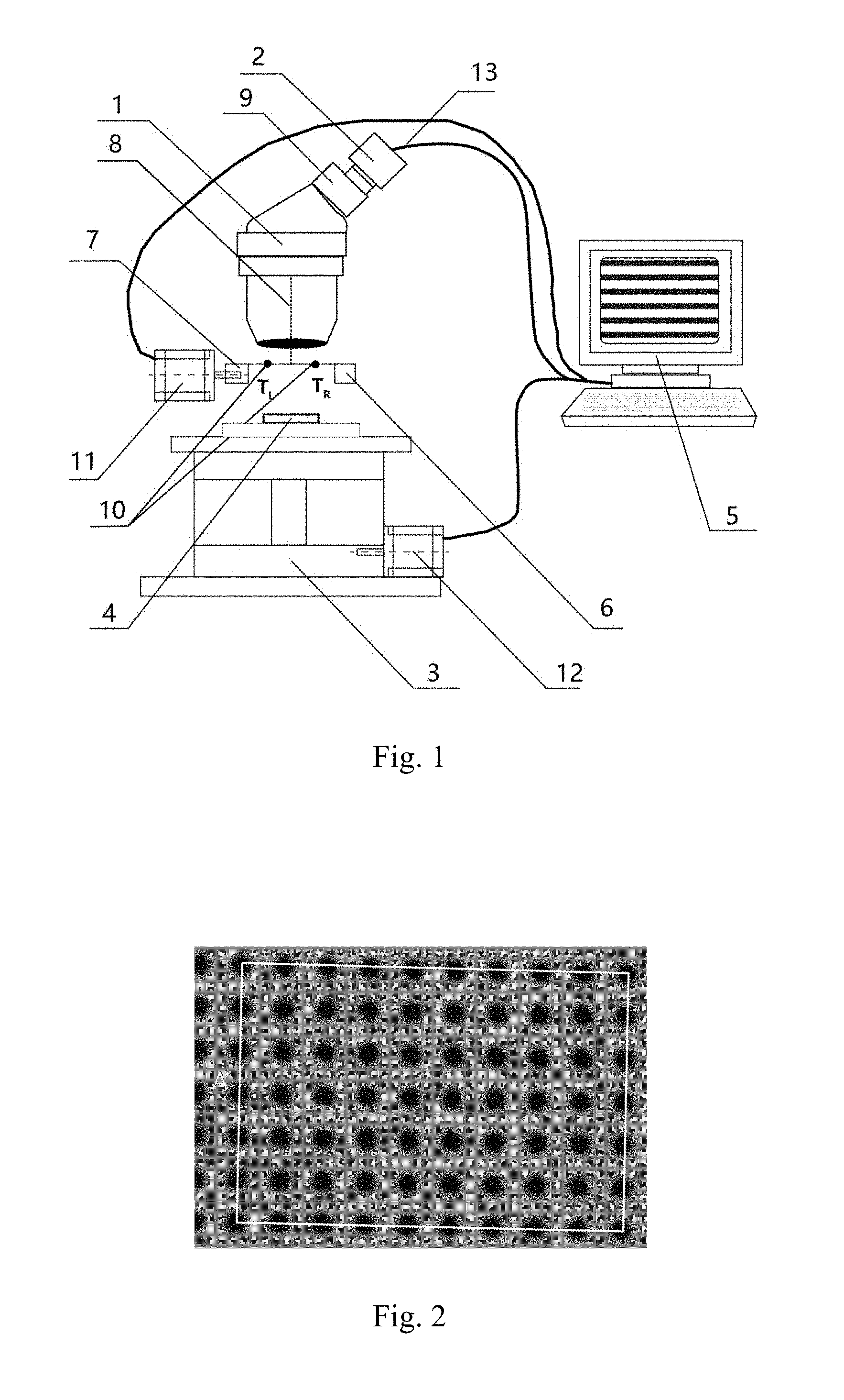
FIG. 1 is a structurally schematic diagram of a microscopic three-dimensional measurement system based on a moving diaphragm provided by the present invention.
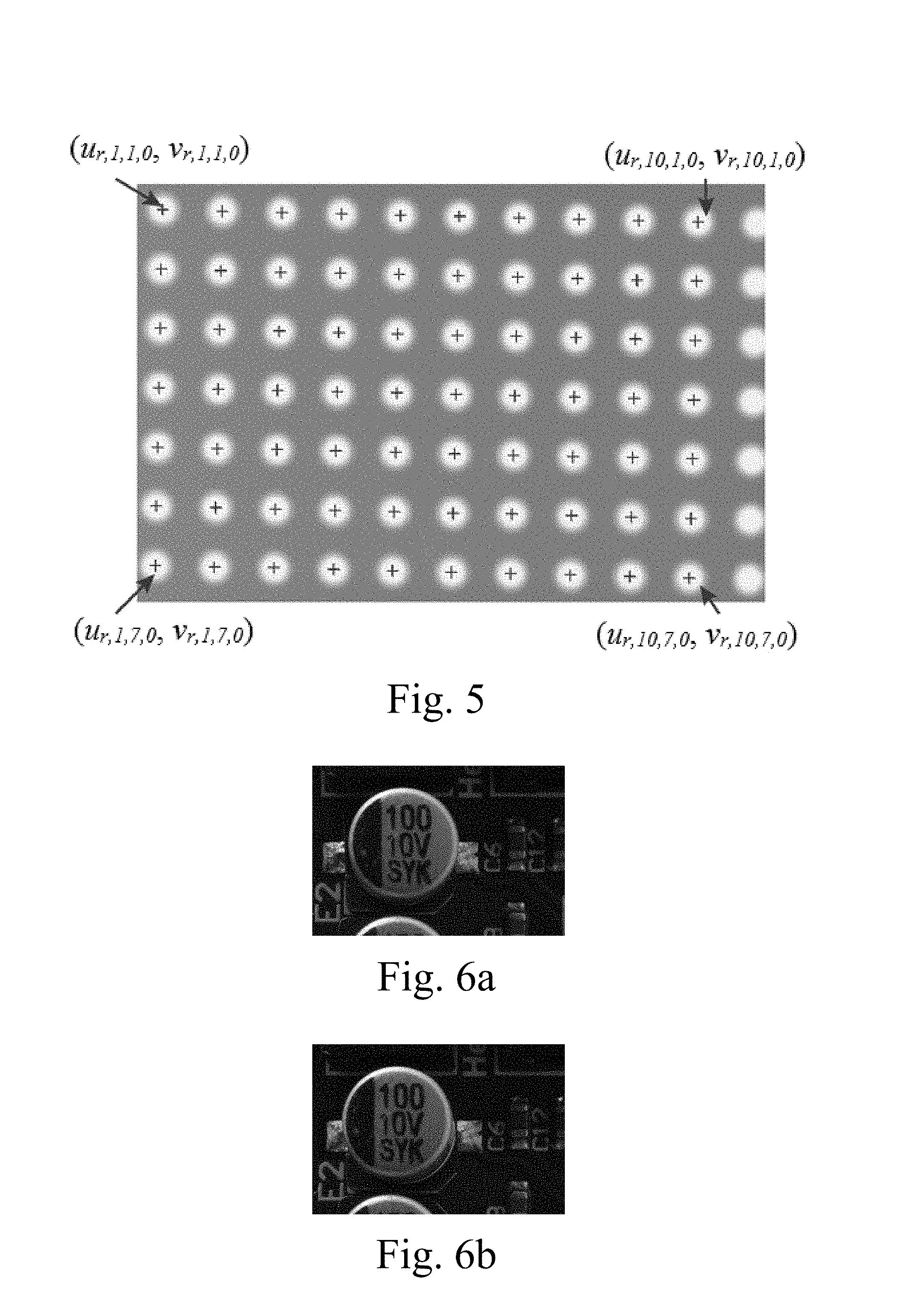
FIG. 2 is a schematic diagram of a determined A' on a dot calibration board.
FIG. 3 is a schematic diagram of a determined A on a dot calibration board.
FIG. 4 shows final coordinate positions of centers of all solid dot areas within the rectangular area corresponding to A in S.sub.0,T.sub.L.
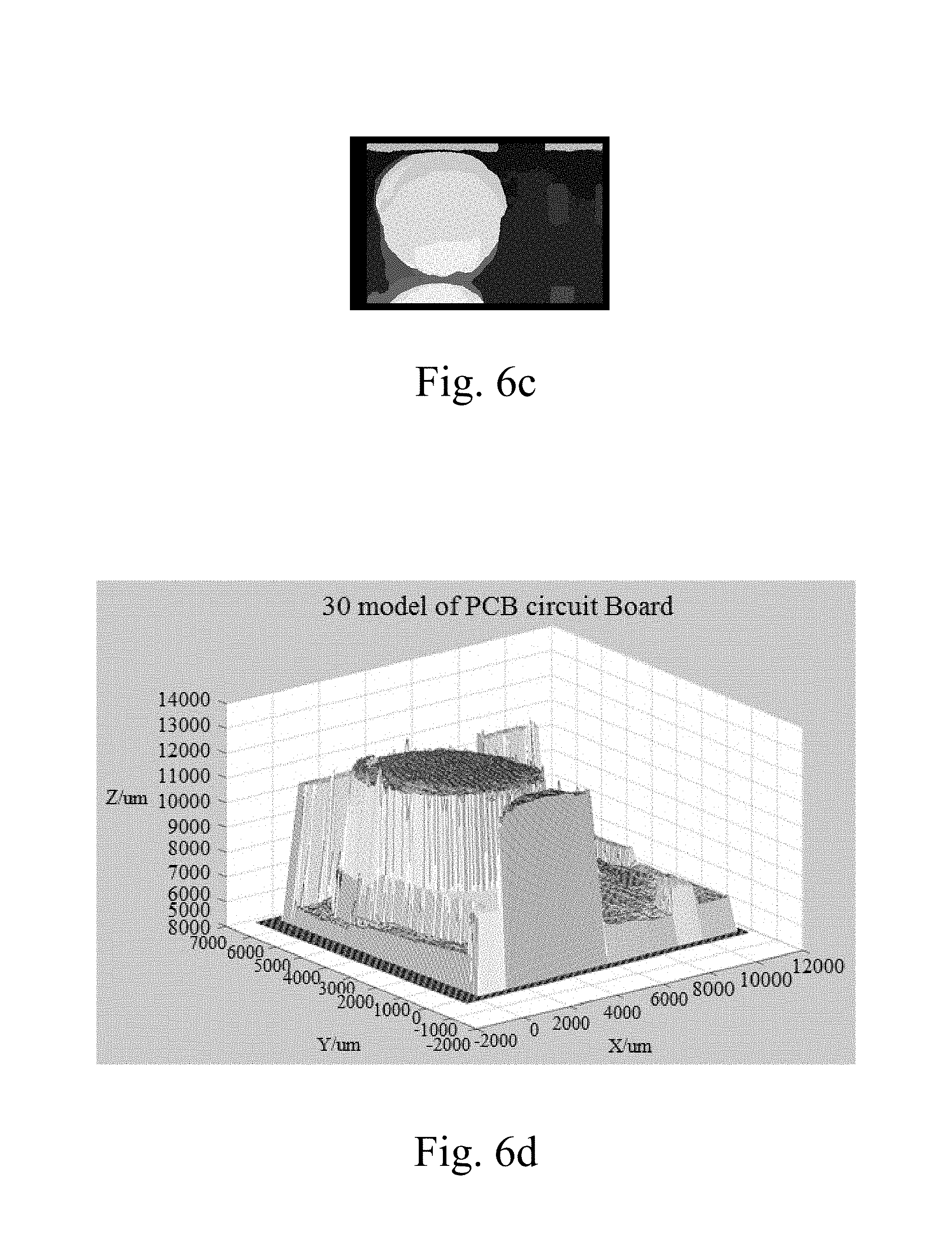
FIG. 5 shows final coordinate positions of centers of all solid dot areas within the rectangular area corresponding to A in S.sub.0,T.sub.R.
FIG. 6a is a collected image of an object to be measured.
FIG. 6b is another collected image of the object to be measured.
FIG. 6c is a disparity map of FIGS. 6a and 6b.
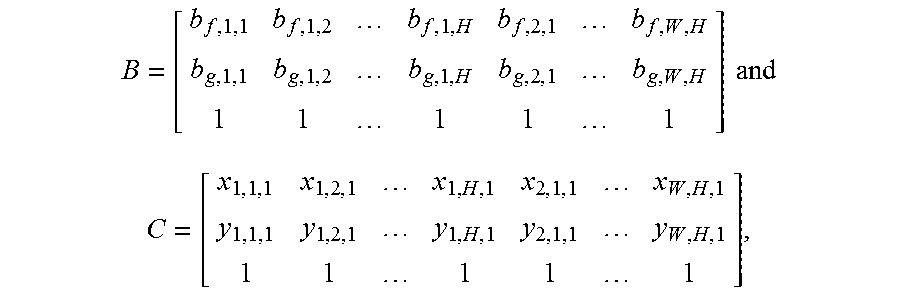
FIG. 6d is a three-dimensional reconstruction map of the object to be measured.
DETAILED DESCRIPTION OF THE PREFERRED EMBODIMENT
The present invention is further described in detailed with accompanying drawings and embodiments as follows.
The present invention provides a microscopic three-dimensional measurement system based on a moving diaphragm, as shown in FIG. 1, which comprises an optical microscope 1, a camera 2 which is installed on the optical microscope 1 and is aligned with an eyepiece 9 of the optical microscope 1, a lifting platform 3 for horizontally placing a dot calibration board 4, and a computer 5, wherein the optical microscope 1 is disposed above the dot calibration board 4 for allowing the eyepiece of the optical microscope 1 to just face towards the dot calibration board 4, an output end 13 of the camera 2 is connected with the computer 5, a drive motor 12 of the lifting platform 3 is connected with the computer 5; a diaphragm 6, which is able to horizontally move, is disposed between the eyepiece of the optical microscope 1 and the dot calibration board 4;
an optical axis 8 of the optical microscope 1 coincides with a moving trajectory of the lifting platform 3, is perpendicular to both the dot calibration board 4 and a moving trajectory of the diaphragm 6.
In this embodiment, the microscopic three-dimensional measurement system further comprises a sliding base 7 for driving the diaphragm 6 to horizontally move, a drive motor 11 of the sliding base 7 is connected with the computer 5.
Also, the present invention provides a microscopic three-dimensional measurement method based on a moving diaphragm, which comprises steps of:
(1) coinciding an optical axis of an optical microscope with a moving trajectory of a lifting platform; horizontally placing a dot calibration board on a top surface of the lifting platform and allowing the dot calibration board to be perpendicular to the optical axis of the optical microscope; allowing a moving trajectory of a diaphragm installed on a sliding base to be perpendicular to the optical axis of the optical microscope; placing the diaphragm between an eyepiece of the optical microscope and the dot calibration board, wherein a center distance between two adjacent solid dots in the dot calibration board is defined as e, a diameter of every solid dot in the dot calibration board is defined as d, d<e, a unit of both the d and the e is mm, a diameter of an aperture 10 of the diaphragm is defined as D, D.di-elect cons.[1,5], and a unit of the D is mm;
wherein: there are twenty solid dots in a horizontal array and twenty solid dots in a vertical array on an upper surface of the selected dot calibration board in experiment, that is, there are totally 20.times.20 solid dots in arrays on the upper surface of the dot calibration board, d is equal to 0.5 mm, e is equal to 1 mm, and D=2 mm in the experiment;
(2) determining an initial position of the aperture of the diaphragm, which comprises positioning a center of the aperture of the diaphragm on the optical axis of the optical microscope through controlling the sliding base; moving left horizontally the diaphragm for a distance L through controlling the sliding base, which means that a distance between the center of the aperture of the diaphragm and the optical axis of the optical microscope is L; determining a current position of the center of the aperture of the diaphragm to be the initial position of the aperture of the diaphragm and recording as T.sub.L, wherein L.di-elect cons.[2, 4], a unit of the L is mm and L=3 mm in the experiment;
determining an initial position of the dot calibration board, which comprises controlling the lifting platform to drive the dot calibration board to move vertically and stopping the vertical movement of the lifting platform when a dot calibration board image observed by an observer from a computer is the clearest; controlling the lifting platform to drive the dot calibration board to move vertically and upwardly, stopping the vertical and upward movement of the lifting platform when the dot calibration board image observed by the observer from the computer changes from the clearest to just fuzzy, recording a current vertical upward moving distance of the lifting platform as Z.sub.S, determining a current position of the dot calibration board to be the initial position of the dot calibration board and recording as P.sub.0, wherein a unit of the Z.sub.S is mm; in the experiment, after the dot calibration board image is the clearest, the lifting platform is controlled to move vertically and upwardly for a distance of Z.sub.S=8 mm, the dot calibration board image changes from the clearest to just fuzzy;
(3) when the dot calibration board is at the initial position P.sub.0, respectively placing four tiny markers at four solid dots on the dot calibration board; making a shape, formed by taking centers of the four solid dots where the four tiny markers are as vertexes, always a rectangle; the observer observing the dot calibration board image displayed by the computer; moving the four tiny markers; displaying the rectangle, which is defined by taking centers of the four solid dots where the four tiny markers are as vertexes, in the dot calibration board image with a largest area and recording as A', wherein an amount of columns of solid dots in a width direction of the A' on the dot calibration board is 10, and an amount of rows of solid dots in a height direction of the A' on the dot calibration board is 7, as shown in FIG. 2;
(4) controlling the sliding base to move right horizontally the diaphragm for a distance of 2L and recording a current position of the aperture of the diaphragm as T.sub.R; the observer observing the dot calibration board image displayed by the computer; moving the four tiny markers; displaying a rectangle which is formed by taking the centers of the four solid dots where the four tiny markers are as vertexes in the dot calibration board image with a largest area and recording as A, saving a current dot calibration board image and recording as S.sub.0,T.sub.R; and then controlling the sliding base to move left horizontally the diaphragm for a distance of 2L, positioning the aperture of the diaphragm at a position of T.sub.L, saving a current dot calibration board image and recording as S.sub.0,T.sub.L, wherein: after moving left horizontally the diaphragm for the distance of 2L, a rectangle which is formed by taking centers of four solid dots where the four tiny markers are as vertexes is still in the dot calibration board image, so the four tiny markers are moved no longer, the A is included in the A', an amount of columns of solid dots in a width direction of the A on the dot calibration board is defined as W, and an amount of rows of solid dots in a height direction of the A on the dot calibration board is defined as H, which means that there are totally W.times.H solid dots of the A on the dot calibration board, both the W and the H are positive integers; in the experiment, the amount of the columns of the solid dots in the width direction of the A on the dot calibration board is W=10, and the amount of the rows of the solid dots in the height direction of the A on the dot calibration board is H=7, as shown in FIG. 3; it can be seen from FIGS. 2 and 3 that an area of the A is equal to an area of the A';
(5) taking a top left corner vertex of the A on the dot calibration board as a coordinate origin O, wherein an X positive axis is defined by pointing to centers of solid dots at a same row, a Y positive axis is defined by pointing to centers of solid dots at a same column, a vertically downwardly moving direction of the lifting platform is defined as a Z positive axis, so as to establish a three-dimensional coordinate system OXYZ;
respectively performing binary processing on the S.sub.0,T.sub.L and the S.sub.0,T.sub.R, obtaining binary images respectively corresponding to the S.sub.0,T.sub.L and the S.sub.0,T.sub.R; processing the binary images of the S.sub.0,T.sub.L through an existing region growing algorithm, obtaining both every solid dot region and multiple candidate coordinate positions of a center of the every solid dot region in the S.sub.0,T.sub.L; similarly, processing the binary images of the S.sub.0,T.sub.R through the existing region growing algorithm, obtaining both every solid dot region and multiple candidate coordinate positions of a center of the every solid dot region in the S.sub.0,T.sub.R; and then determining any one of the multiple candidate coordinate positions of the center of the every solid dot region within a rectangle area in the S.sub.0,T.sub.L corresponding to the A, to a final coordinate position of the center of the solid dot region; recording a final coordinate position of a center of a i.sup.th column and j.sup.th row solid dot region within the rectangle area in the S.sub.0,T.sub.L corresponding to the A as (u.sub.l,i,j,0,v.sub.l,i,j,0); similarly, determining any one of the multiple candidate coordinate positions of the center of the every solid dot region within a rectangle area in the S.sub.0,T.sub.R corresponding to the A, to a final coordinate position of the center of the solid dot region; recording a final coordinate position of a center of a i.sup.th column and j.sup.th row solid dot region within the rectangle area in the S.sub.0,T.sub.R corresponding to the A as (u.sub.r,i,j,0,v.sub.r,i,j,0), wherein: both the i and the j are positive integers, 1.ltoreq.i.ltoreq.W, 1.ltoreq.j.ltoreq.H FIG. 4 shows final coordinate positions of centers of all solid dot regions within the rectangle in the S.sub.0,T.sub.L corresponding to the A, FIG. 5 shows final coordinate positions of centers of all solid dot regions within the rectangle in the S.sub.0,T.sub.R corresponding to the A;
(6) controlling the lifting platform to drive dot calibration board to move vertically and downwardly for a distance of .DELTA..alpha., recording a current position of the dot calibration board as P.sub.1, recording a current dot calibration board image and recording as S.sub.1,T.sub.L; and then controlling the lifting platform to move right horizontally the diaphragm for a distance of 2L, positioning the aperture of the diaphragm at a position of T.sub.R, saving a current dot calibration board image and recording as S.sub.1,T.sub.R; and then controlling the lifting platform to move left horizontally the diaphragm for a distance of 2L, positioning the aperture of the diaphragm at a position of T.sub.L, wherein .DELTA..alpha..di-elect cons.(Z.sub.S/100, Z.sub.S/50), a unit of the .DELTA..alpha. is mm; in the experiment, .DELTA..alpha.=0.1 mm;
(7) respectively performing binary processing on the S.sub.1,T.sub.L and the S.sub.1,T.sub.R obtaining binary images respectively corresponding to the S.sub.1,T.sub.L and the S.sub.1,T.sub.R; processing the binary images of the S.sub.1,T.sub.L through the existing region growing algorithm, obtaining both every solid dot region and multiple candidate coordinate positions of a center of the every solid dot region in the S.sub.1,T.sub.L; similarly, processing the binary images of the S.sub.1,T.sub.R through the existing region growing algorithm, obtaining both every solid dot region and multiple candidate coordinate positions of a center of the every solid dot region in the S.sub.1,T.sub.R; and then according to the multiple candidate coordinate positions of the center of the every solid dot region within a rectangle area in the S.sub.1,T.sub.L corresponding to the A, determining a final coordinate position of the center of the every solid dot region within the rectangle area in the S.sub.1,T.sub.L corresponding to the A; recording a final coordinate position of a center of a i.sup.th column and j.sup.th row solid dot region within the rectangle area in the S.sub.1,T.sub.L corresponding to the A as (u.sub.l,i,j,1,v.sub.l,i,j,1), wherein the (u.sub.l,i,j,1,v.sub.l,i,j,1) is a candidate coordinate position with a smallest Euclidean distance to the (u.sub.l,i,j,0,v.sub.l,i,j,0) in the multiple candidate coordinate positions of the center of the i.sup.th column and j.sup.th row solid dot region within the rectangle area in the S.sub.1,T.sub.L corresponding to the A; similarly, according to the multiple candidate coordinate positions of the center of the every solid dot region within a rectangle area in the S.sub.1,T.sub.R corresponding to the A, determining a final coordinate position of the center of the every solid dot region within the rectangle area in the S.sub.1,T.sub.R corresponding to the A; recording a final coordinate position of a center of a i.sup.th column and j.sup.th row solid dot region within the rectangle area in the S.sub.1,T.sub.R corresponding to the A as (u.sub.r,i,j,1,v.sub.r,i,j,1), wherein the (u.sub.l,i,j,1,v.sub.l,i,j,1) is a candidate coordinate position with a smallest Euclidean distance to the (u.sub.r,i,j,0,v.sub.r,i,j,0) in the multiple candidate coordinate positions of the center of the i.sup.th column and j.sup.th row solid dot region within the rectangle area in the S.sub.1,T.sub.R corresponding to the A;
calculating three-dimensional coordinates on the three-dimensional coordinate system OXYZ of a center of every solid dot within the A on the dot calibration board after the lifting platform driving the dot calibration board to firstly move vertically and downwardly for a distance of .DELTA..alpha., recording three-dimensional coordinates on the three-dimensional coordinate system OXYZ of a center of a i.sup.th column and j.sup.th row solid dot within the A on the dot calibration board after the lifting platform driving the dot calibration board to firstly move vertically and downwardly for the distance of .DELTA..alpha. as (x.sub.i,j,1,y.sub.i,j,1,z.sub.i,j,1), wherein x.sub.i,j,1=(i-1).times.e, y.sub.i,j,1=(j-1).times.e and z.sub.i,j,1=1.times..DELTA..alpha.; and then calculating a multi-aperture imaging bias corresponding to every solid dot within the A on the dot calibration board after the lifting platform driving the dot calibration board to firstly move vertically and downwardly for the distance of .DELTA..alpha., recording a multi-aperture imaging bias corresponding to a i.sup.th column and j.sup.th row solid dot within the A on the dot calibration board after the lifting platform driving the dot calibration board to firstly move vertically and downwardly for the distance of .DELTA..alpha. as .DELTA.u.sub.i,j,1, here, .DELTA.u.sub.i,j,1=u.sub.l,i,j,1-u.sub.r,i,j,1, wherein x.sub.i,j,1,y.sub.i,j,1,z.sub.i,j,1, respectively represent an X-axis coordinate, a Y-axis coordinate and a Z-axis coordinate on the three-dimensional coordinate system OXYZ of the center of the i.sup.th column and j.sup.th row solid dot within the A on the dot calibration board after the lifting platform driving the dot calibration board to firstly move vertically and downwardly for the distance of .DELTA..alpha.;
(8) repeating the steps (6) and (7) for (N-1) times, recording a current position of the dot calibration board as P.sub.k after the lifting platform drives the dot calibration board to move downwardly and vertically for .DELTA..alpha. at a k.sup.th time, recording a current dot calibration board image as S.sub.k,T.sub.L; recording a dot calibration board image as S.sub.k,T.sub.R after moving right horizontally the diaphragm for 2L; recording a final coordinate positions of a center of a i.sup.th column and j.sup.th row solid dot region within a rectangle area in the S.sub.k,T.sub.L corresponding to the A as (u.sub.l,i,j,k,v.sub.l,i,j,k), wherein the (u.sub.l,i,j,k,v.sub.l,i,j,k) is a candidate coordinate position with a smallest Euclidean distance to the (u.sub.l,i,j,k-1,v.sub.l,i,j,k-1) in multiple candidate coordinate positions of the center of the i.sup.th column and j.sup.th row solid dot region within the rectangle area in the S.sub.k,T.sub.R corresponding to the A; recording a final coordinate positions of a center of a i.sup.th column and j.sup.th row solid dot region within a rectangle area in the S.sub.k,T.sub.R corresponding to the A as (u.sub.r,i,j,k,v.sub.r,i,j,k), wherein the (u.sub.r,i,j,k,v.sub.r,i,j,k) is a candidate coordinate position with a smallest Euclidean distance to the (u.sub.r,i,j,k-1,v.sub.r,i,j,k-1) in multiple candidate coordinate positions of the center of the i.sup.th column and j.sup.th row solid dot region within the rectangle area in the S.sub.k,T.sub.R corresponding to the A; recording three-dimensional coordinates on the three-dimensional coordinate system OXYZ of a center of a i.sup.th column and j.sup.th row solid dot within the A on the dot calibration board after the lifting platform driving the dot calibration board to move vertically and downwardly at the k.sup.th time for the distance of .DELTA..alpha. as (x.sub.i,j,k,y.sub.i,j,k,z.sub.i,j,k), wherein x.sub.i,j,k=(i-1).times.e, y.sub.i,j,k=(j-1).times.e and z.sub.i,j,k=k.times..DELTA..alpha.; and then recording a multi-aperture imaging bias corresponding to a i.sup.th column and j.sup.th row solid dot within the A on the dot calibration board after the lifting platform driving the dot calibration board to move vertically and downwardly at the k.sup.th time for the distance of .DELTA..alpha. as .DELTA.u.sub.i,j,k, here, .DELTA.u.sub.i,j,k=u.sub.l,i,j,k-u.sub.r,i,j,k, wherein N is a positive integer,
.times..DELTA..alpha. ##EQU00008## ".left brkt-bot. .right brkt-bot." represents a round downward operator, in the experiment,
.times..DELTA..alpha..times. ##EQU00009## k is a positive integer, 1.ltoreq.k.ltoreq.N, x.sub.i,j,k,y.sub.i,j,k,z.sub.i,j,k, respectively represent an X-axis coordinate, a Y-axis coordinate and a Z-axis coordinate on the three-dimensional coordinate system OXYZ of the center of the i.sup.th column and j.sup.th row solid dot within the A on the dot calibration board after the lifting platform driving the dot calibration board to move vertically and downwardly at the k.sup.th time for the distance of .DELTA..alpha.;
(9) forming a data pair by combining the Z-axis coordinate on the three-dimensional coordinate system OXYZ of the center of every solid dot within the A on the dot calibration board after the lifting platform driving the dot calibration board to move vertically and downwardly every time for the distance of .DELTA..alpha., with a corresponding multi-aperture imaging bias, recording the data pair formed by the z.sub.i,j,k and the .DELTA.u.sub.i,j,k as (z.sub.i,j,k,.DELTA.u.sub.i,j,k); and then through a quadratic polynomial (such as polyfit function in matlab), fitting N data pairs corresponding to every solid dot within the A on the dot calibration board, obtaining W.times.H relationships between the Z-axis coordinate on the three-dimensional coordinate system of the center of every solid dot within the A on the dot calibration board and a corresponding multi-aperture imaging bias, defining a relationship between the Z-axis coordinate z.sub.i,j on the three-dimensional coordinate system of the center of the i.sup.th column and j.sup.th row solid dot within the A on the dot calibration board and a corresponding multi-aperture imaging bias .DELTA.u.sub.i,j as z.sub.i,j=a.sub.i,j.DELTA.u.sub.i,j.sup.2+b.sub.i,j.DELTA.u.sub.i,j+c.sub- .i,j, wherein all of the a.sub.i,j, the b.sub.i,j and the c.sub.i,j are coefficients obtained by fitting, there are totally (W.times.H) coefficients,
wherein the coefficients obtained by fitting in the experiment are as follows:
a.sub.i,j:
TABLE-US-00001 -0.00961 -0.0096 -0.00964 -0.00958 -0.00958 -0.00957 -0.00956 -0.0096 -0.0- 096 -0.00965 -0.00958 -0.00964 -0.00961 -0.00958 -0.00956 -0.00956 -0.00956 -0.0096 -0.- 0096 -0.00968 -0.0096 -0.00965 -0.00966 -0.00961 -0.00955 -0.00955 -0.00957 -0.00959 -0.- 00962 -0.00966 -0.0096 -0.00969 -0.00961 -0.00962 -0.00959 -0.00953 -0.00963 -0.00961 -0.- 00958 -0.00961 -0.00963 -0.00968 -0.00965 -0.00961 -0.00958 -0.00959 -0.00958 -0.00962 -0- .00958 -0.00966 -0.00965 -0.00965 -0.00969 -0.00964 -0.0096 -0.00958 -0.00954 -0.00961 -0.- 00965 -0.00961 -0.0097 -0.00964 -0.00964 -0.00966 -0.00966 -0.00963 -0.00957 -0.0096 -0.0- 0965 -0.00965
b.sub.i,j:
TABLE-US-00002 24.83339 24.8516 24.88844 24.87788 24.88734 24.89163 24.87441 24.87593 24.- 86716 24.85142 24.84147 24.85505 24.88535 24.88658 24.88992 24.89163 24.8849 24.87489 24.- 86526 24.86709 24.84489 24.87328 24.88345 24.88832 24.89727 24.90436 24.88557 24.87556 24- .86509 24.8562 24.85058 24.87775 24.88554 24.87997 24.89715 24.89413 24.88574 24.87641 24- .86283 24.85096 24.85257 24.87851 24.88056 24.89459 24.89183 24.90372 24.88639 24.8775 24.- 86363 24.85499 24.86275 24.87129 24.87489 24.90061 24.89573 24.89983 24.89117 24.87087 24- .86188 24.84953 24.86099 24.85875 24.87774 24.89924 24.89612 24.89734 24.88754 24.87342 24- .85497 24.84557
c.sub.i,j:
TABLE-US-00003 8707.143 8699.579 8690.631 8681.277 8677.786 8676.766 8674.264 8671.414 86- 72.015 8669.033 8713.259 8707.069 8695.824 8687.93 8682.237 8678.059 8675.34 8672.187 8673- .513 8678.021 8723.347 8715.544 8701.178 8696.167 8687.479 8682.676 8678.895 8677.755 86- 83.217 8684.188 8734.714 8725.511 8707.566 8700.457 8696.685 8689.52 8688.212 8689.241 869- 4.18 8694.097 8745.906 8733.868 8719.69 8710.663 8705.266 8700.975 8698.997 8703.131 870- 7.286 8708.989 8758.818 8745.963 8736.928 8724.119 8719.096 8715.395 8713.612 8717.242 87- 22.915 8722.619 8773.964 8761.481 8753.725 8744.4 8736.065 8734.078 8733 8732.323 8737.393- 8739.263
calculating a corresponding focal plane moving distance of every solid dot within the A on the dot calibration board after the lifting platform drives the dot calibration board to move downwardly and vertically every time for a distance of .DELTA..alpha., recording a corresponding focal plane moving distance of the i.sup.th column and j.sup.th row solid dot within the A on the dot calibration board as .DELTA.z.sub.i,j,k after the lifting platform drives the dot calibration board to move vertically and downwardly at the k.sup.th time for the distance of .DELTA..alpha., here, .DELTA.z.sub.i,j,k=z.sub.i,j,k-c.sub.i,j; and then forming a data pair by combining a corresponding focal plane moving distance of every solid dot within the A on the dot calibration board after the lifting platform drives the dot calibration board to move vertically and downwardly every time for the distance of .DELTA..alpha., with a corresponding multi-aperture imaging bias, recording the data pair formed by the .DELTA.z.sub.i,j,k and .DELTA.u.sub.i,j,k as (.DELTA.z.sub.i,j,k,.DELTA.u.sub.i,j,k); and then through a quadratic polynomial (such as polyfit function in matlab), fitting N.times.W.times.H data pairs corresponding to all solid dots within the A on the dot calibration board, obtaining a relationship between a focal plane moving distance .DELTA.z corresponding to any point on the dot calibration board and a corresponding multi-aperture imaging bias .DELTA.u, defining the relationship as .DELTA.z.DELTA.z=a.DELTA.u.sup.2+b.DELTA.u+c, wherein all of the a, the b and the c are coefficients obtained by fitting, a quadratic polynomial of the .DELTA.z and the .DELTA.u obtained by fitting in the experiment is .DELTA.z=0.0096.DELTA.u.sup.2 24.8756 .DELTA.u-0.0027;
according to the X-axis coordinate and the Y-axis coordinate on the three-dimensional coordinate system OXYZ of the center of every solid dot within the A on the dot calibration board after the lifting platform firstly drives the dot calibration board to move vertically and downwardly for the distance of .DELTA..alpha., determining (W.times.H) three-dimensional scattered points and three-dimensional coordinates of an i.sup.th column and j.sup.th row three-dimensional scattered point to (x.sub.i,j,1,y.sub.i,j,1,c.sub.i,j); and then through a plane fitting method (such as createSurfaceFit function in matlab), plane-fitting the (W.times.H) three-dimensional scattered points, obtaining a space plane with an equation of z=b.sub.1+b.sub.2x+b.sub.3y, here, all of the b.sub.1, the b.sub.2 and the b.sub.3 are coefficients obtained by fitting, (x,y,z) presents three-dimensional coordinates of space points in the three-dimensional coordinate system OXYZ, the x,y,z respectively represent an X-axis coordinate, a Y-axis coordinate and a Z-axis coordinate of every space point in the three-dimensional coordinate system OXYZ, an equation of the space plane obtained by fitting in the experiment is z=8.6943.times.10.sup.3+0.0041x+0.0104y;
(10) determining a relationship, between corresponding coordinate positions (u,v) of any obtained point in the dot calibration board images and on the dot calibration board when the aperture of the diaphragm is at a position of T.sub.L after the lifting platform drives the dot calibration board move vertically and downwardly every time for the distance of .DELTA..alpha., and a corresponding focal plane moving distance .DELTA.z of the point on the dot calibration board, defining the relationship between the (u,v) and the .DELTA.z as
.times..DELTA..times..times..times..DELTA..times..times..times..DELTA..ti- mes..times..times..DELTA..times..times. ##EQU00010## here, 1.ltoreq.u.ltoreq.W', 1.ltoreq.v.ltoreq.H', W' represents a width of an obtained dot calibration board image when the aperture of the diaphragm is at a position of T.sub.L after the lifting platform drives the dot calibration board move vertically and downwardly every time for the distance of .DELTA..alpha., H' represents a height thereof, all of the a.sub.f, b.sub.f, d.sub.f, a.sub.g, b.sub.g and d.sub.g are quadratic polynomial coefficients;
forming a data pair by combining an X-coordinate of a final coordinate position of a center of every solid dot region within a rectangle area corresponding to the A in the obtained dot calibration board image after the lifting platform drives the dot calibration board to move vertically and downwardly every time for the distance of .DELTA..alpha., with a corresponding focal plane moving distance of every solid dot within the A on the dot calibration board, recording the data pair formed by u.sub.l,i,j,k and .DELTA.z.sub.i,j,k as (u.sub.l,i,j,k,.DELTA.z.sub.i,j,k); and then through a quadratic polynomial (such as polyfit function in matlab), fitting N data pairs corresponding to every solid dot of both every solid dot region within a rectangle area corresponding to the A in the dot calibration board image and within the A on the dot calibration board, obtaining a relationship between an X-coordinate of a final coordinate position of a center of every solid region within a rectangle area corresponding to the A in the dot calibration board image, and a corresponding focal plane moving distance of every solid dot within the A on the dot calibration board; defining a relationship between an X-coordinate u.sub.l,i,j of a final coordinate position of a center of an i.sup.th column and j.sup.th row solid region within the rectangle area corresponding to the A in the dot calibration board image, and a corresponding focal plane moving distance .DELTA.z.sub.i,j of the i.sup.th column and j.sup.th row solid dot within the A on the dot calibration board as u.sub.l,i,j=a.sub.f,i,j.times..DELTA.z.sub.i,j.sup.2+b.sub.f,i,j.times..D- ELTA.z.sub.i,j+d.sub.f,i,j, here, all of the a.sub.f,i,j, b.sub.f,i,j, and d.sub.f,i,j are coefficients obtained by fitting, there are totally (W.times.H) coefficients;
forming a data pair by combining a Y-coordinate of the final coordinate position of the center of every solid dot region within the rectangle area corresponding to the A in the obtained dot calibration board image after the lifting platform drives the dot calibration board to move vertically and downwardly every time for the distance of .DELTA..alpha., with the corresponding focal plane moving distance of every solid dot within the A on the dot calibration board, recording the data pair formed by v.sub.l,i,j,k and .DELTA.z.sub.i,j,k as (v.sub.l,i,j,k,.DELTA.z.sub.i,j,k); and then through the quadratic polynomial (such as polyfit function in matlab), fitting N data pairs corresponding to every solid dot of both every solid dot region within the rectangle area corresponding to the A in the dot calibration board image and within the A on the dot calibration board, obtaining a relationship between a Y-coordinate of the final coordinate position of the center of every solid region within the rectangle area corresponding to the A in the dot calibration board image, and the corresponding focal plane moving distance of every solid dot within the A on the dot calibration board; defining a relationship between a Y-coordinate v.sub.l,i,j of the final coordinate position of the center of the i.sup.th column and j.sup.th row solid region within the rectangle area corresponding to the A in the dot calibration board image, and the corresponding focal plane moving distance .DELTA.z.sub.i,j of the i.sup.th column and j.sup.th row solid dot within the A on the dot calibration board as v.sub.l,i,j=a.sub.g,i,j.times..DELTA.z.sub.i,j.sup.2+b.sub.g,i,j.times..D- ELTA.z.sub.i,j+d.sub.g,i,j, here, all of the a.sub.g,i,j, b.sub.g,i,j and d.sub.g,i,j are coefficients obtained by fitting, there are totally (W.times.H) coefficients,
wherein coefficients obtained by fitting in the experiment are as follows:
a.sub.f,i,j:
TABLE-US-00004 -0.0000002682 -0.0000001684 -0.0000000678 0.0000000331 0.0000001308 -0.0000002731 -0.0000001711 -0.0000000685 0.0000000304 0.0000001291 -0.0000002736 -0.0000001733 -0.0000000688 0.0000000295 0.0000001251 -0.0000002747 -0.0000001736 -0.0000000731 0.0000000287 0.0000001250 -0.0000002776 -0.0000001761 -0.0000000741 0.0000000241 0.0000001231 -0.0000002797 -0.0000001776 -0.0000000764 0.0000000223 0.0000001223 -0.0000002799 -0.0000001802 -0.0000000784 0.0000000196 0.0000001203 0.0000002300 0.0000003309 0.0000004354 0.0000005332 0.0000006341 0.0000002283 0.0000003273 0.0000004317 0.0000005315 0.0000006364 0.0000002253 0.0000003242 0.0000004253 0.0000005329 0.0000006310 0.0000002227 0.0000003241 0.0000004254 0.0000005277 0.0000006299 0.0000002211 0.0000003218 0.0000004240 0.0000005248 0.0000006269 0.0000002186 0.0000003172 0.0000004203 0.0000005170 0.0000006232 0.0000002177 0.0000003140 0.0000004172 0.0000005212 0.0000006210
b.sub.f,i,j:
TABLE-US-00005 -0.01959 -0.01278 -0.00595 0.000864 0.007635 0.014376 0.021167 0.027991 0.- 034825 0.04164 -0.01976 -0.01294 -0.00611 0.000704 0.007472 0.014223 0.020998 0.027813 0.- 034655 0.041469 -0.01992 -0.0131 -0.00626 0.000545 0.007314 0.014052 0.020829 0.027647 0.0- 34489 0.041315 -0.02007 -0.01327 -0.00642 0.000401 0.007147 0.013899 0.020665 0.027488 0.- 03433 0.04116 -0.02023 -0.01342 -0.00658 0.00022 0.006988 0.013734 0.020494 0.027331 0.0- 3417 0.040999 -0.0204 -0.01359 -0.00675 5.94E-05 0.006832 0.013569 0.020334 0.027176 0.0- 34015 0.04085 -0.02058 -0.01375 -0.00693 -0.00012 0.00666 0.013409 0.020183 0.027014 0.0- 33881 0.040697
d.sub.f,i,j:
TABLE-US-00006 698.9545 1134.878 1572.476 2008.914 2443.186 2876.134 3310.072 3747.182 41- 85.173 4621.562 689.1317 1124.921 1562.612 1998.906 2433.094 2866.039 3299.88 3736.804 417- 4.782 4611.323 679.1408 1114.871 1552.657 1988.847 2423.023 2855.954 3289.692 3726.677 41- 64.635 4601.131 669.0325 1104.787 1542.628 1978.914 2412.937 2845.889 3279.56 3716.629 415- 4.602 4591.048 658.8592 1094.625 1532.379 1968.695 2402.749 2835.829 3269.479 3706.539 41- 44.648 4581.085 648.4953 1084.403 1522.107 1958.427 2392.582 2825.688 3259.446 3696.561 41- 34.529 4571.239 637.9991 1073.984 1511.646 1948.148 2382.355 2815.532 3249.388 3686.574 41- 24.729 4561.426
a.sub.g,i,j:
TABLE-US-00007 -0.0000002751 -0.0000002724 -0.0000002705 -0.0000002668 -0.0000002620 -0.0000001782 -0.0000001763 -0.0000001694 -0.0000001719 -0.0000001677 -0.0000000789 -0.0000000770 -0.0000000743 -0.0000000678 -0.0000000652 0.0000000239 0.0000000266 0.0000000278 0.0000000304 0.0000000295 0.0000001211 0.0000001252 0.0000001268 0.0000001274 0.0000001303 0.0000002236 0.0000002259 0.0000002264 0.0000002293 0.0000002301 0.0000003210 0.0000003226 0.0000003253 0.0000003274 0.0000003284 -0.0000002627 -0.0000002607 -0.0000002600 -0.0000002556 -0.0000002562 -0.0000001649 -0.0000001626 -0.0000001622 -0.0000001591 -0.0000001568 -0.0000000662 -0.0000000611 -0.0000000598 -0.0000000580 -0.0000000557 0.0000000353 0.0000000349 0.0000000398 0.0000000418 0.0000000423 0.0000001336 0.0000001370 0.0000001395 0.0000001405 0.0000001441 0.0000002350 0.0000002357 0.0000002375 0.0000002416 0.0000002460 0.0000003257 0.0000003325 0.0000003348 0.0000003381 0.0000003419
b.sub.g,i,j:
TABLE-US-00008 -0.01792 -0.01774 -0.01758 -0.01741 -0.01724 -0.01709 -0.01693 -0.01678 -0- .01662 -0.01647 -0.01113 -0.01096 -0.01077 -0.01063 -0.01046 -0.01029 -0.01013 -0.00999 -0- .00983 -0.00968 -0.00432 -0.00415 -0.004 -0.00383 -0.00366 -0.00351 -0.00335 -0.00318 -0.0- 0304 -0.00287 0.002485 0.002635 0.002804 0.002962 0.003123 0.003288 0.003439 0.0036 0.00- 3761 0.003917 0.009283 0.009445 0.009607 0.009764 0.009908 0.010069 0.01024 0.010393 0.0- 10551 0.010719 0.016098 0.016254 0.016409 0.016567 0.016716 0.016864 0.017026 0.017197 0.- 017358 0.01754 0.022897 0.023056 0.023202 0.023348 0.023483 0.023647 0.023812 0.023975 0.- 024146 0.024317
d.sub.g,i,j:
TABLE-US-00009 360.4958 370.7643 381.2076 391.4 401.4607 411.376 421.1094 431.0625 440.86- 61 450.7236 796.7715 806.9556 817.4735 827.484 837.4645 847.3911 857.2331 867.185 876.- 7994 886.7162 1232.478 1242.557 1252.793 1262.807 1272.793 1282.678 1292.483 1302.416 13- 12.132 1322.156 1668.586 1678.645 1688.814 1698.655 1708.618 1718.492 1728.351 1738.236 17- 48.025 1757.997 2104.283 2114.246 2124.2 2133.953 2143.747 2153.571 2163.468 2173.443 2183- .315 2193.393 2540.621 2550.345 2560.311 2569.959 2579.764 2589.515 2599.321 2609.464 26- 19.382 2629.605 2976.576 2986.161 2996.019 3005.602 3015.243 3024.984 3034.917 3044.903 30- 55.041 3065.332
wherein a.sub.f,i,j and b.sub.f,i,j form a data pair to obtain (W.times.H) data pairs; and then the (W.times.H) data pairs are linearly fitted (through the polyfit function in matlab), a relationship between a quadratic polynomial a.sub.f and a quadratic polynomial coefficient b.sub.f is obtained, the relationship is defined as a.sub.f=k.sub.f,a.times.b.sub.f+c.sub.f,a, here, both k.sub.f,a and c.sub.f,a are coefficients obtained by fitting;
wherein d.sub.f,i,j and b.sub.f,i,j form a data pair to obtain (W.times.H) data pairs; and then the (W.times.H) data pairs are linearly fitted (through the polyfit function in matlab), a relationship between a quadratic polynomial coefficient d.sub.f and a quadratic polynomial coefficient b.sub.f is obtained, the relationship is defined as d.sub.f=k.sub.f,d.times.b.sub.f+c.sub.f,d, here, both k.sub.f,d and c.sub.f,d are coefficients obtained by fitting;
wherein a.sub.g,i,j and b.sub.g,i,j form a data pair to obtain (W.times.H) data pairs; and then the (W.times.H) data pairs are linearly fitted (through the polyfit function in matlab), a relationship between a quadratic polynomial coefficient a.sub.g and a quadratic polynomial coefficient b.sub.g is obtained, the relationship is defined as a.sub.g=k.sub.g,a.times.b.sub.g+c.sub.g,a, here, both k.sub.g,a and c.sub.g,a are coefficients obtained by fitting;
wherein d.sub.g,i,j and b.sub.g,i,j form a data pair to obtain (W.times.H) data pairs; and then the (W.times.H) data pairs are linearly fitted (through the polyfit function in matlab), a relationship between a quadratic polynomial coefficient d.sub.g and a quadratic polynomial coefficient b.sub.g is obtained, the relationship is defined as d.sub.g=k.sub.g,d.times.b.sub.g+c.sub.g,d here, both k.sub.g,d and c.sub.g,d are coefficients obtained by fitting;
the coefficients obtained by fitting in the experiment are as follows: k.sub.f,a=1.4731.times.10.sup.-5, c.sub.f,a=2.0620.times.10.sup.-8, k.sub.f,d=6.4068.times.10.sup.4, c.sub.f,d=1.9548.times.10.sup.3, k.sub.g,a=1.4615.times.10.sup.-5, c.sub.g,a=1.3818.times.10.sup.-8, k.sub.g,d=6.4117.times.10.sup.4 and c.sub.g,d=1.5078.times.10.sup.3;
defining
.times..times. ##EQU00011## ##EQU00011.2## and then defining M=BC.sup.-1, wherein
.times..times..times..times. ##EQU00012## in the experiment;
(12) placing the object to be measured on a top surface of the lifting platform, making the object to be measured perpendicular to the optical axis of the optical microscope; and then positioning the aperture of the diaphragm at the position of T.sub.L through controlling the sliding base, saving a current image of the object to be measured and taking as a first image; and then controlling the sliding base to move the diaphragm right horizontally for the distance of 2L, positioning the aperture of the diaphragm at the position of T.sub.R, saving a current image of the object to be measured and taking as a second image; and then through a stereo matching algorithm (such as disparity function in matlab), three-dimensionally matching the first image with the second image, obtaining a disparity map between the first image and the second image, recording the disparity map as I.sub.d, wherein a size of all the first image, the second image and the I.sub.d is M.sub.d.times.N.sub.d, the first image collected in the experiment is shown in FIG. 6a, the second image collected in the experiment is shown in FIG. 6b, the obtained disparity map is shown in FIG. 6c, all of which has a size of 1296.times.864;
(13) defining .DELTA.u=G(x.sub.d,y.sub.d), wherein .DELTA.z.sub.d represents a corresponding focal plane moving distance of the I.sub.d, .DELTA.z.sub.d=a.DELTA.u.sup.2+b.DELTA.u+c; obtaining a value of .DELTA.z.sub.d based on the .DELTA.u=G(x.sub.d,y.sub.d) and the .DELTA.z.sub.d=a.DELTA.u.sup.2+b.DELTA.u+c, wherein G(x.sub.d,y.sub.d) represent gray values of a pixel point with coordinate positions of (x.sub.d,y.sub.d) in the I.sub.d, 1.ltoreq.x.sub.d.ltoreq.M.sub.d, 1.ltoreq.y.sub.d.ltoreq.N.sub.d;
based on a.sub.f=k.sub.f,a.times.b.sub.f+c.sub.f,a, d.sub.f=k.sub.f,d.times.b.sub.f+c.sub.f,d, a.sub.g=k.sub.g,a.times.b.sub.g+c.sub.g,a, a.sub.g=k.sub.g,a.times.b.sub.g+c.sub.g,a and
.times..DELTA..times..times..times..DELTA..times..times..times..DELTA..ti- mes..times..times..DELTA..times..times. ##EQU00013## obtaining
.times..DELTA..times..times..times..DELTA..times..times..DELTA..times..ti- mes..times..DELTA..times..times..times..DELTA..times..times..DELTA..times.- .times. ##EQU00014## based on u=x.sub.d, v=y.sub.d, .DELTA.z=.DELTA.z.sub.d, the
.times..DELTA..times..times..times..DELTA..times..times..DELTA..times..ti- mes..times..DELTA..times..times..times..DELTA..times..times..DELTA..times.- .times. ##EQU00015## obtaining values of b.sub.f and b.sub.g, and respectively recording as b.sub.f(x.sub.d,y.sub.d) and b.sub.g(x.sub.d,y.sub.d);
calculating
.function..function..function..function..function. ##EQU00016## obtaining coordinate values x(x.sub.d,y.sub.d) of x and coordinate values y(x.sub.d,y.sub.d) of y, wherein M.sup.-1 is an inverse array of M;
based on x=x(x.sub.d,y.sub.d), y=y(x.sub.d,y.sub.d) and z=b.sub.1+b.sub.2x+b.sub.3y, obtaining an intermediate value of z and recording as z.sub.0; and then calculating coordinate values of the z, recording as z(x.sub.d,y.sub.d) wherein z(x.sub.d,y.sub.d)=z.sub.0-.DELTA.z.sub.d;
taking (x(x.sub.d,y.sub.d),y(x.sub.d,y.sub.d),z(x.sub.d,y.sub.d)) as three-dimensional coordinates of a reconstructed space point; and
(14) reconstructing three-dimensional coordinates of all space points using all pixel points in the I.sub.d based on the step (13), and obtaining a three-dimensional reconstruction map, wherein FIG. 6d shows the three-dimensional reconstruction map of the object to be measured.
* * * * *
D00000
D00001
D00002
D00003
D00004
M00001
M00002
M00003
M00004
M00005
M00006
M00007
M00008

M00009

M00010

M00011

M00012

M00013

M00014

M00015

M00016

M00017

M00018

M00019

M00020

M00021

M00022

M00023

XML
uspto.report is an independent third-party trademark research tool that is not affiliated, endorsed, or sponsored by the United States Patent and Trademark Office (USPTO) or any other governmental organization. The information provided by uspto.report is based on publicly available data at the time of writing and is intended for informational purposes only.
While we strive to provide accurate and up-to-date information, we do not guarantee the accuracy, completeness, reliability, or suitability of the information displayed on this site. The use of this site is at your own risk. Any reliance you place on such information is therefore strictly at your own risk.
All official trademark data, including owner information, should be verified by visiting the official USPTO website at www.uspto.gov. This site is not intended to replace professional legal advice and should not be used as a substitute for consulting with a legal professional who is knowledgeable about trademark law.