Systems and methods for reliable software update in a network of moving things including, for example, autonomous vehicles
Pereira Cabral , et al.
U.S. patent number 10,360,021 [Application Number 15/653,270] was granted by the patent office on 2019-07-23 for systems and methods for reliable software update in a network of moving things including, for example, autonomous vehicles. This patent grant is currently assigned to Veniam, Inc.. The grantee listed for this patent is Veniam, Inc.. Invention is credited to Carlos Eduardo Braga Ameixieira, Henrique Manuel Pereira Cabral.


View All Diagrams
| United States Patent | 10,360,021 |
| Pereira Cabral , et al. | July 23, 2019 |
Systems and methods for reliable software update in a network of moving things including, for example, autonomous vehicles
Abstract
Communication network architectures, systems and methods for supporting a network of mobile nodes. As a non-limiting example, various aspects of this disclosure provide communication network architectures, systems, and methods for supporting a dynamically configurable communication network comprising a complex array of both static and moving communication nodes (e.g., the Internet of moving things). Aspects of the disclosure disclose systems and methods for reliable software update in a network of moving things including, for example, autonomous vehicles.
| Inventors: | Pereira Cabral; Henrique Manuel (Matosinhos, PT), Braga Ameixieira; Carlos Eduardo (Oporto, PT) | ||||||||||
|---|---|---|---|---|---|---|---|---|---|---|---|
| Applicant: |
|
||||||||||
| Assignee: | Veniam, Inc. (Mountain View,
CA) |
||||||||||
| Family ID: | 61191684 | ||||||||||
| Appl. No.: | 15/653,270 | ||||||||||
| Filed: | July 18, 2017 |
Prior Publication Data
| Document Identifier | Publication Date | |
|---|---|---|
| US 20180052681 A1 | Feb 22, 2018 | |
Related U.S. Patent Documents
| Application Number | Filing Date | Patent Number | Issue Date | ||
|---|---|---|---|---|---|
| 62376955 | Aug 19, 2016 | ||||
| Current U.S. Class: | 1/1 |
| Current CPC Class: | H04W 48/20 (20130101); G06F 16/00 (20190101); G06F 9/445 (20130101); G06F 8/65 (20130101); H04L 12/4641 (20130101); G06F 8/656 (20180201); G06F 2221/034 (20130101); H04W 76/10 (20180201) |
| Current International Class: | G06F 8/65 (20180101); G06F 8/656 (20180101); G06F 9/445 (20180101); H04L 12/46 (20060101); G06F 16/00 (20190101); H04W 48/20 (20090101); H04W 76/10 (20180101) |
References Cited [Referenced By]
U.S. Patent Documents
| 7574706 | August 2009 | Meulemans |
| 8225312 | July 2012 | DiCarlo |
| 8588756 | November 2013 | Baldan |
| 8862113 | October 2014 | Berionne |
| 2006/0075001 | April 2006 | Canning |
| 2010/0333080 | December 2010 | Keys |
| 2012/0030731 | February 2012 | Bhargava |
| 2014/0222899 | August 2014 | Supramaniam |
| 2016/0162275 | June 2016 | Morley |
| 2016/0294614 | October 2016 | Searle |
| 2017/0195459 | July 2017 | e Costa |
| 2018/0052681 | February 2018 | Pereira Cabral |
Other References
|
Junginger, "The Multi-Ring Topology--High-Performance Group Communication in Peer-to-Peer Networks" 2002, Proceedings of the second international conference on peer-to-peer computing, 2002 (Year: 2002). cited by examiner . Vanbever, "HotSwap: Correct and Efficient Controller Upgrades for Software-Defined Networks", 2013, ACM 978-1-4503-2178--May 13, 2008 (Year: 2013). cited by examiner. |
Primary Examiner: Morshed; Hossain M
Attorney, Agent or Firm: McAndrews, Held & Malloy, Ltd.
Parent Case Text
CROSS-REFERENCE TO RELATED APPLICATIONS/INCORPORATION BY REFERENCE
This patent application makes reference to, claims priority to, and claims benefit from U.S. Provisional Patent Application Ser. No. 62/376,955, filed on Aug. 19, 2016, and titled "Systems and Methods for Reliable Software Update in a Network of Moving Things," which is hereby incorporated herein by reference in its entirety. The present application is also related to U.S. Provisional Application Ser. No. 62/221,997, titled "Integrated Communication Network for a Network of Moving Things," filed on Sep. 22, 2015; U.S. Provisional Application Ser. No. 62/222,016, titled "Systems and Methods for Synchronizing a Network of Moving Things," filed on Sep. 22, 2015; U.S. Provisional Application Ser. No. 62/222,042, titled "Systems and Methods for Managing a Network of Moving Things," filed on Sep. 22, 2015; U.S. Provisional Application Ser. No. 62/222,066, titled "Systems and Methods for Monitoring a Network of Moving Things," filed on Sep. 22, 2015; U.S. Provisional Application Ser. No. 62/222,077, titled "Systems and Methods for Detecting and Classifying Anomalies in a Network of Moving Things," filed on Sep. 22, 2015; U.S. Provisional Application Ser. No. 62/222,098, titled "Systems and Methods for Managing Mobility in a Network of Moving Things," filed on Sep. 22, 2015; U.S. Provisional Application Ser. No. 62/222,121, titled "Systems and Methods for Managing Connectivity a Network of Moving Things," filed on Sep. 22, 2015; U.S. Provisional Application Ser. No. 62/222,135, titled "Systems and Methods for Collecting Sensor Data in a Network of Moving Things," filed on Sep. 22, 2015; U.S. Provisional Application Ser. No. 62/222,145, titled "Systems and Methods for Interfacing with a Network of Moving Things," filed on Sep. 22, 2015; U.S. Provisional Application Ser. No. 62/222,150, titled "Systems and Methods for Interfacing with a User of a Network of Moving Things," filed on Sep. 22, 2015; U.S. Provisional Application Ser. No. 62/222,168, titled "Systems and Methods for Data Storage and Processing for a Network of Moving Things," filed on Sep. 22, 2015; U.S. Provisional Application Ser. No. 62/222,183, titled "Systems and Methods for Vehicle Traffic Management in a Network of Moving Things," filed on Sep. 22, 2015; U.S. Provisional Application Ser. No. 62/222,186, titled "Systems and Methods for Environmental Management in a Network of Moving Things," filed on Sep. 22, 2015; U.S. Provisional Application Ser. No. 62/222,190, titled "Systems and Methods for Port Management in a Network of Moving Things," filed on Sep. 22, 2015; U.S. Provisional Patent Application Ser. No. 62/222,192, titled "Communication Network of Moving Things," filed on Sep. 22, 2015; U.S. Provisional Application Ser. No. 62/244,828, titled "Utilizing Historical Data to Correct GPS Data in a Network of Moving Things," filed on Oct. 22, 2015; U.S. Provisional Application Ser. No. 62/244,930, titled "Using Anchors to Correct GPS Data in a Network of Moving Things," filed on Oct. 22, 2015; U.S. Provisional Application Ser. No. 62/246,368, titled "Systems and Methods for Inter-Application Communication in a Network of Moving Things," filed on Oct. 26, 2015; U.S. Provisional Application Ser. No. 62/246,372, titled "Systems and Methods for Probing and Validating Communication in a Network of Moving Things," filed on Oct. 26, 2015; U.S. Provisional Application Ser. No. 62/250,544, titled "Adaptive Rate Control for Vehicular Networks," filed on Nov. 4, 2015; U.S. Provisional Application Ser. No. 62/273,878, titled "Systems and Methods for Reconfiguring and Adapting Hardware in a Network of Moving Things," filed on Dec. 31, 2015; U.S. Provisional Application Ser. No. 62/253,249, titled "Systems and Methods for Optimizing Data Gathering in a Network of Moving Things," filed on Nov. 10, 2015; U.S. Provisional Application Ser. No. 62/257,421, titled "Systems and Methods for Delay Tolerant Networking in a Network of Moving Things," filed on Nov. 19, 2015; U.S. Provisional Application Ser. No. 62/265,267, titled "Systems and Methods for Improving Coverage and Throughput of Mobile Access Points in a Network of Moving Things," filed on Dec. 9, 2015; U.S. Provisional Application Ser. No. 62/270,858, titled "Channel Coordination in a Network of Moving Things," filed on Dec. 22, 2015; U.S. Provisional Application Ser. No. 62/257,854, titled "Systems and Methods for Network Coded Mesh Networking in a Network of Moving Things," filed on Nov. 20, 2015; U.S. Provisional Application Ser. No. 62/260,749, titled "Systems and Methods for Improving Fixed Access Point Coverage in a Network of Moving Things," filed on Nov. 30, 2015; U.S. Provisional Application Ser. No. 62/273,715, titled "Systems and Methods for Managing Mobility Controllers and Their Network Interactions in a Network of Moving Things," filed on Dec. 31, 2015; U.S. Provisional Application Ser. No. 62/281,432, titled "Systems and Methods for Managing and Triggering Handovers of Mobile Access Points in a Network of Moving Things," filed on Jan. 21, 2016; U.S. Provisional Application Ser. No. 62/268,188, titled "Captive Portal-related Control and Management in a Network of Moving Things," filed on Dec. 16, 2015; U.S. Provisional Application Ser. No. 62/270,678, titled "Systems and Methods to Extrapolate High-Value Data from a Network of Moving Things," filed on Dec. 22, 2015; U.S. Provisional Application Ser. No. 62/272,750, titled "Systems and Methods for Remote Software Update and Distribution in a Network of Moving Things," filed on Dec. 30, 2015; U.S. Provisional Application Ser. No. 62/278,662, titled "Systems and Methods for Remote Configuration Update and Distribution in a Network of Moving Things," filed on Jan. 14, 2016; U.S. Provisional Application Ser. No. 62/286,243, titled "Systems and Methods for Adapting a Network of Moving Things Based on User Feedback," filed on Jan. 22, 2016; U.S. Provisional Application Ser. No. 62/278,764, titled "Systems and Methods to Guarantee Data Integrity When Building Data Analytics in a Network of Moving Things," Jan. 14, 2016; U.S. Provisional Application Ser. No. 62/286,515, titled "Systems and Methods for Self-Initialization and Automated Bootstrapping of Mobile Access Points in a Network of Moving Things," filed on Jan. 25, 2016; U.S. Provisional Application Ser. No. 62/295,602, titled "Systems and Methods for Power Management in a Network of Moving Things," filed on Feb. 16, 2016; and U.S. Provisional Application Ser. No. 62/299,269, titled "Systems and Methods for Automating and Easing the Installation and Setup of the Infrastructure Supporting a Network of Moving Things," filed on Feb. 24, 2016; each of which is hereby incorporated herein by reference in its entirety for all purposes.
Claims
What is claimed is:
1. A method of performing reliable software updates at a first node of a wireless network comprising a plurality of nodes and a cloud-based system communicatively coupled to storage containing software updates for the plurality of nodes, the method comprising: periodically communicating, by the first node to the cloud-based system, a request for an identifier of a software update for application to the first node; in response to the request, receiving an identifier of a respective software update for application to the first node; determining whether the received identifier is on a list of identifiers of software updates blacklisted by the first node; determining whether the first node is a member node of a group of nodes designated to download an available software update that is not blacklisted at the member node and without regard to status information about the available software update that is shared by neighbor nodes of the member node; communicating with one or more neighbor nodes of the first node to determine status of the identified software update at the one or more neighbor nodes, if the first node is not a member of the group of nodes; downloading the software update identified by the received identifier, if the first node is a member of the group of nodes; and applying the downloaded software update to the first node.
2. The method according to claim 1, where communicating with the one or more neighbor nodes of the first node to determine status of the identified software update at the one or more neighbor nodes comprises: receiving software update status information from the one or more neighbor nodes; and determining whether to download the software update identified by the received identifier to the first node, based on the software update status information received from the one or more neighbor nodes.
3. The method according to claim 1, wherein the one or more neighbor nodes are within direct wireless communication range of the first node.
4. The method according to claim 1, wherein the method further comprises: determining whether measurements of the operation of the updated software on the first node match expected operation represented by information received with the downloaded software update; and sending notification of failure of performance of the first node to match the information representative of the expected operation.
5. The method according to claim 1, wherein method further comprises: sharing the list of identifiers of software updates blacklisted by the first node with the one or more neighbor nodes.
6. The method according to claim 1, wherein nodes of the plurality of nodes are designated as members of the group of nodes by the cloud-based system.
7. The method according to claim 1, wherein the plurality of nodes comprise a plurality of fixed nodes at known geographic locations and a plurality of mobile nodes located in respective vehicles operating in a geographic area served by the wireless network.
8. A non-transitory computer-readable medium on which is stored one or more code sections, each code section comprising instructions executable by one or more processors, the instructions for causing the one or more processors to perform the steps of a method of performing reliable software updates at a first node of a wireless network comprising a plurality of nodes and a cloud-based system communicatively coupled to storage containing software updates for the plurality of nodes, the steps of the method comprising: periodically communicating, by the first node to the cloud-based system, a request for an identifier of a software update for application to the first node; in response to the request, receiving an identifier of a respective software update for application to the first node; determining whether the received identifier is on a list of identifiers of software updates blacklisted by the first node; determining whether the first node is a member node of a group of nodes designated to download an available software update that is not blacklisted at the member node and without regard to status information about the available software update that is shared by neighbor nodes of the member node; communicating with one or more neighbor nodes of the first node to determine status of the identified software update at the one or more neighbor nodes, if the first node is not a member of the group of nodes; downloading the software update identified by the received identifier, if the first node is a member of the group of nodes; and applying the downloaded software update to the first node.
9. The non-transitory computer-readable medium according to claim 8, where communicating with the one or more neighbor nodes of the first node to determine status of the identified software update at the one or more neighbor nodes comprises: receiving software update status information from the one or more neighbor nodes; and determining whether to download the software update identified by the received identifier to the first node, based on the software update status information received from the one or more neighbor nodes.
10. The non-transitory computer-readable medium according to claim 8, wherein the one or more neighbor nodes are within direct wireless communication range of the first node.
11. The non-transitory computer-readable medium according to claim 8, wherein the steps of the method further comprise: determining whether measurements of the operation of the updated software on the first node match expected operation represented by information received with the downloaded software update; and sending notification of failure of performance of the first node to match the information representative of the expected operation.
12. The non-transitory computer-readable medium according to claim 8, wherein the steps of the method further comprise: sharing the list of identifiers of software updates blacklisted by the first node with the one or more neighbor nodes.
13. The non-transitory computer-readable medium according to claim 8, wherein nodes of the plurality of nodes are designated as members of the group of nodes by the cloud-based system.
14. The non-transitory computer-readable medium according to claim 8, wherein the plurality of nodes comprise a plurality of fixed nodes at known geographic locations and a plurality of mobile nodes located in respective vehicles operating in a geographic area served by the wireless network.
15. A system for performing reliable software updates at a first node of a wireless network comprising a plurality of nodes and a cloud-based system communicatively coupled to storage containing software updates for the plurality of nodes, the system comprising: one or more processors operably coupled to storage of the first node and to at least one wireless communication interface configured to communicate using the wireless network, the one or more processors operable to: periodically communicate, by the first node to the cloud-based system, a request for an identifier of a software update for application to the first node; in response to the request, receive an identifier of a respective software update for application to the first node; determine whether the received identifier is on a list of identifiers of software updates blacklisted by the first node; determine whether the first node is a member node of a group of nodes designated to download an available software update that is not blacklisted at the member node and without regard to status information about the available software update that is shared by neighbor nodes of the member node; communicate with one or more neighbor nodes of the first node to determine status of the identified software update at the one or more neighbor nodes, if the first node is not a member of the group of nodes; download the software update identified by the received identifier, if the first node is a member of the group of nodes; and apply the downloaded software update to the first node.
16. The system according to claim 15, where communicating with the one or more neighbor nodes of the first node to determine status of the identified software update at the one or more neighbor nodes comprises: receiving software update status information from the one or more neighbor nodes; and determining whether to download the software update identified by the received identifier to the first node, based on the software update status information received from the one or more neighbor nodes.
17. The system according to claim 15, wherein the one or more neighbor nodes are within direct wireless communication range of the first node.
18. The system according to claim 15, wherein the method further comprises: determining whether measurements of the operation of the updated software on the first node match expected operation represented by information received with the downloaded software update; and sending notification of failure of performance of the first node to match the information representative of the expected operation.
19. The system according to claim 15, wherein method further comprises: sharing the list of identifiers of software updates blacklisted by the first node with the one or more neighbor nodes.
20. The system according to claim 15, wherein nodes of the plurality of nodes are designated as members of the group of nodes by the cloud-based system.
21. The system according to claim 15, wherein the plurality of nodes comprises a plurality of fixed nodes at known geographic locations and a plurality of mobile nodes located in respective vehicles operating in a geographic area served by the wireless network.
Description
BACKGROUND
Current communication networks are unable to adequately support communication environments involving mobile and static nodes. As a non-limiting example, current communication networks are unable to adequately support a network comprising a complex array of both moving and static nodes (e.g., the Internet of moving things, autonomous vehicle networks, etc.). Limitations and disadvantages of conventional methods and systems will become apparent to one of skill in the art, through comparison of such approaches with some aspects of the present methods and systems set forth in the remainder of this disclosure with reference to the drawings.
BRIEF DESCRIPTION OF SEVERAL VIEWS OF THE DRAWINGS
FIG. 1 shows a block diagram of a communication network, in accordance with various aspects of this disclosure.
FIG. 2 shows a block diagram of a communication network, in accordance with various aspects of this disclosure.
FIG. 3 shows a diagram of a metropolitan area network, in accordance with various aspects of this disclosure.
FIG. 4 shows a block diagram of a communication network, in accordance with various aspects of this disclosure.
FIGS. 5A-5C show a plurality of network configurations illustrating the flexibility and/or and resiliency of a communication network, in accordance with various aspects of this disclosure.
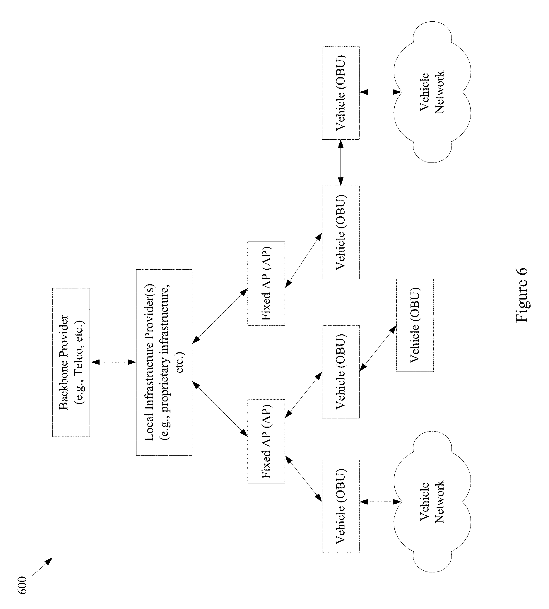
FIG. 6 shows a block diagram of an example communication network, in accordance with various aspects of the present disclosure.
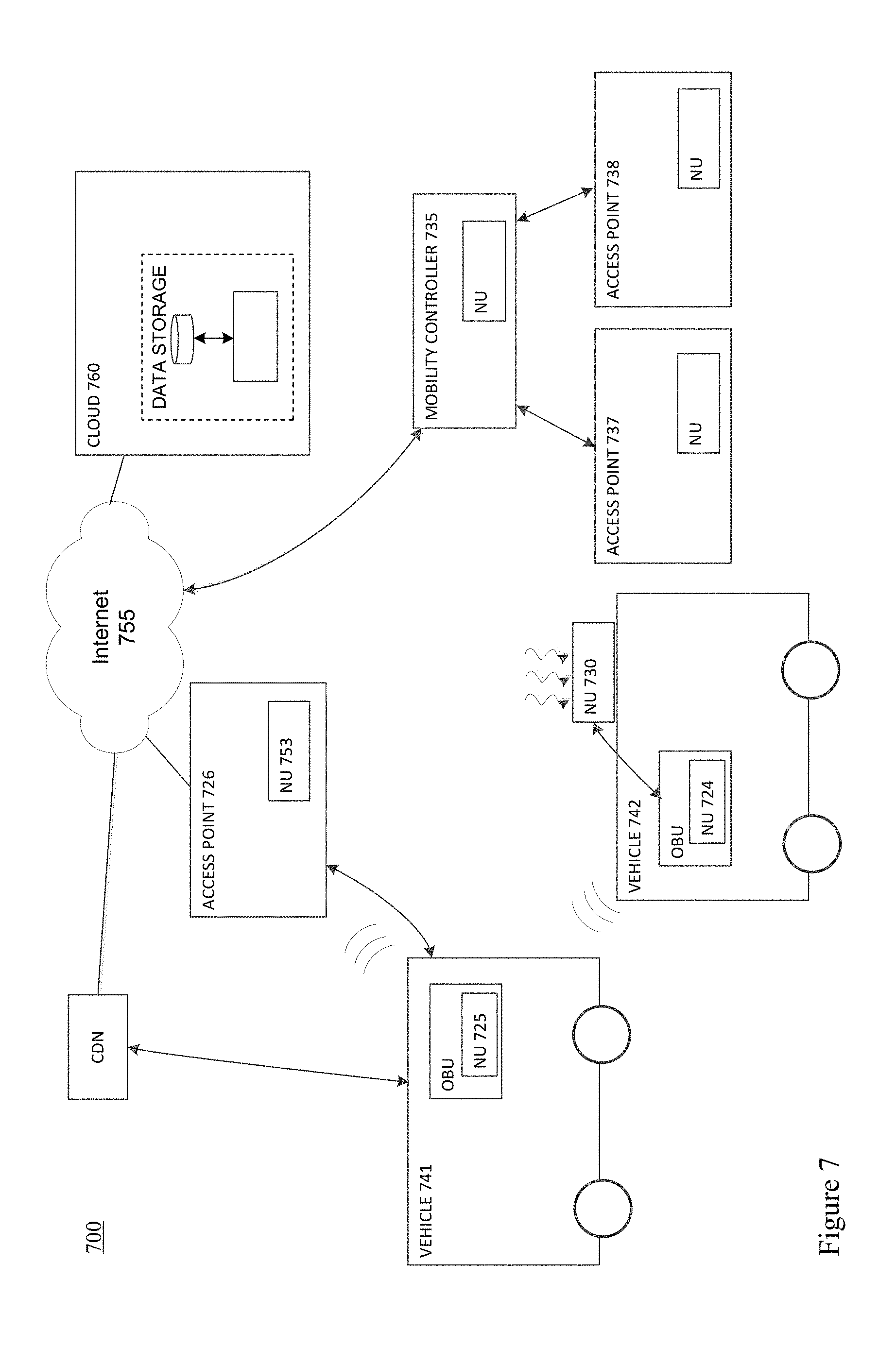
FIG. 7 shows a block diagram of an example communication network, in accordance with various aspects of the present disclosure.
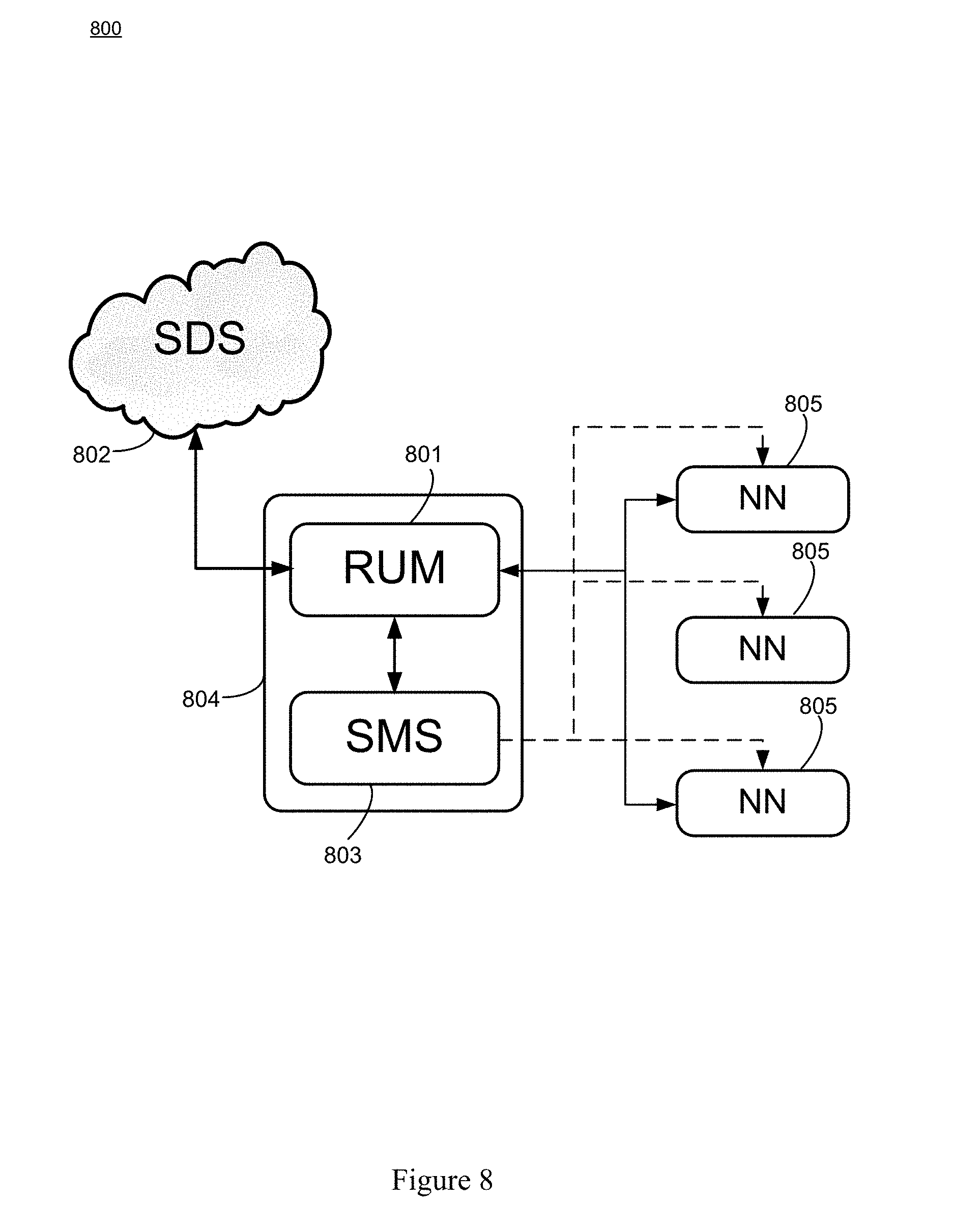
FIG. 8 is a high level block diagram illustrating the elements of an example system that supports reliable software updates, in accordance with various aspects of the present disclosure.
FIG. 9 is a block diagram illustrating a network of moving things that includes a number of network nodes that may communicate with one another and with system functionality of a Cloud, including the network entity referred to herein as a software distribution server (SDS), in accordance with various aspects of the present disclosure.
FIGS. 10A-10C are a flowchart illustrating the actions of an example method of operating the nodes of a network to enable the network to provide reliable software updates, in accordance with various aspects of the present disclosure.
SUMMARY
Various aspects of this disclosure provide communication network architectures, systems and methods for supporting a network of mobile and/or static nodes. As a non-limiting example, various aspects of this disclosure provide communication network architectures, systems, and methods for supporting a dynamically configurable communication network comprising a complex array of both static and moving communication nodes (e.g., the Internet of moving things, autonomous vehicle networks, etc.). For example, a communication network implemented in accordance with various aspects of the present disclosure may operate in one of a plurality of modalities comprising various fixed nodes, mobile nodes, and/or a combination thereof, which are selectable to achieve any of a variety of system goals.
DETAILED DESCRIPTION OF VARIOUS ASPECTS OF THE DISCLOSURE
As utilized herein the terms "circuits" and "circuitry" refer to physical electronic components (i.e., hardware) and any software and/or firmware ("code") that may configure the hardware, be executed by the hardware, and or otherwise be associated with the hardware. As used herein, for example, a particular processor and memory (e.g., a volatile or non-volatile memory device, a general computer-readable medium, etc.) may comprise a first "circuit" when executing a first one or more lines of code and may comprise a second "circuit" when executing a second one or more lines of code. Additionally, a circuit may comprise analog and/or digital circuitry. Such circuitry may, for example, operate on analog and/or digital signals. It should be understood that a circuit may be in a single device or chip, on a single motherboard, in a single chassis, in a plurality of enclosures at a single geographical location, in a plurality of enclosures distributed over a plurality of geographical locations, etc. Similarly, the term "module" may, for example, refer to a physical electronic components (i.e., hardware) and any software and/or firmware ("code") that may configure the hardware, be executed by the hardware, and or otherwise be associated with the hardware.
As utilized herein, circuitry is "operable" to perform a function whenever the circuitry comprises the necessary hardware and code (if any is necessary) to perform the function, regardless of whether performance of the function is disabled, or not enabled (e.g., by a user-configurable setting, factory setting or trim, etc.).
As utilized herein, "and/or" means any one or more of the items in the list joined by "and/or". As an example, "x and/or y" means any element of the three-element set {(x), (y), (x, y)}. That is, "x and/or y" means "one or both of x and y." As another example, "x, y, and/or z" means any element of the seven-element set {(x), (y), (z), (x, y), (x, z), (y, z), (x, y, z)}. That is, "x, y, and/or z" means "one or more of x, y, and z." As utilized herein, the terms "e.g.," and "for example," "exemplary," and the like set off lists of one or more non-limiting examples, instances, or illustrations.
The terminology used herein is for the purpose of describing particular examples only and is not intended to be limiting of the disclosure. As used herein, the singular forms are intended to include the plural forms as well, unless the context clearly indicates otherwise. It will be further understood that the terms "comprises," "includes," "comprising," "including," "has," "have," "having," and the like when used in this specification, specify the presence of stated features, integers, steps, operations, elements, and/or components, but do not preclude the presence or addition of one or more other features, integers, steps, operations, elements, components, and/or groups thereof.
It will be understood that, although the terms first, second, etc. may be used herein to describe various elements, these elements should not be limited by these terms. These terms are only used to distinguish one element from another element. Thus, for example, a first element, a first component or a first section discussed below could be termed a second element, a second component or a second section without departing from the teachings of the present disclosure. Similarly, various spatial terms, such as "upper," "lower," "side," and the like, may be used in distinguishing one element from another element in a relative manner. It should be understood, however, that components may be oriented in different manners, for example an electronic device may be turned sideways so that its "top" surface is facing horizontally and its "side" surface is facing vertically, without departing from the teachings of the present disclosure.
With the proliferation of the mobile and/or static things (e.g., devices, machines, people, etc.) and logistics for such things to become connected to each other (e.g., in the contexts of smart logistics, transportation, environmental sensing, etc.), a platform that is for example always-on, robust, scalable and secure that is capable of providing connectivity, services and Internet access to such things (or objects), anywhere and anytime is desirable. Efficient power utilization within the various components of such system is also desirable.
Accordingly, various aspects of the present disclosure provide a fully-operable, always-on, responsive, robust, scalable, secure platform/system/architecture to provide connectivity, services and Internet access to all mobile things and/or static things (e.g., devices, machines, people, access points, end user devices, sensors, etc.) anywhere and anytime, while operating in an energy-efficient manner.
Various aspects of the present disclosure provide a platform that is flexibly configurable and adaptable to the various requirements, features, and needs of different environments, where each environment may be characterized by a respective level of mobility and density of mobile and/or static things, and the number and/or types of access to those things. Characteristics of various environments may, for example, include high mobility of nodes (e.g., causing contacts or connections to be volatile), high number of neighbors, high number of connected mobile users, mobile access points, availability of multiple networks and technologies (e.g., sometimes within a same area), etc. For example, the mode of operation of the platform may be flexibly adapted from environment to environment, based on each environment's respective requirements and needs, which may be different from other environments. Additionally for example, the platform may be flexibly optimized (e.g., at design/installation time and/or in real-time) for different purposes (e.g., to reduce the latency, increase throughput, reduce power consumption, load balance, increase reliability, make more robust with regard to failures or other disturbances, etc.), for example based on the content, service or data that the platform provides or handles within a particular environment.
In accordance with various aspects of the present disclosure, many control and management services (e.g., mobility, security, routing, etc.) are provided on top of the platform (e.g., directly, using control overlays, using containers, etc.), such services being compatible with the services currently deployed on top of the Internet or other communication network(s).
The communication network (or platform), in whole or in part, may for example be operated in public and/or private modes of operation, for example depending on the use case. The platform may, for example, operate in a public or private mode of operation, depending on the use-case (e.g., public Internet access, municipal environment sensing, fleet operation, etc.).
Additionally for example, in an implementation in which various network components are mobile, the transportation and/or signal control mechanisms may be adapted to serve the needs of the particular implementation. Also for example, wireless transmission power and/or rate may be adapted (e.g., to mitigate interference, to reduce power consumption, to extend the life of network components, etc.).
Various example implementations of a platform, in accordance with various aspects of the present disclosure, are capable of connecting different subsystems, even when various other subsystems that may normally be utilized are unavailable. For example, the platform may comprise various built-in redundancies and fail-recovery mechanisms. For example, the platform may comprise a self-healing capability, self-configuration capability, self-adaptation capability, etc. The protocols and functions of the platform may, for example, be prepared to be autonomously and smoothly configured and adapted to the requirements and features of different environments characterized by different levels of mobility and density of things (or objects), the number/types of access to those things. For example, various aspects of the platform may gather context parameters that can influence any or all decisions. Such parameters may, for example, be derived locally, gathered from a neighborhood, fixed APs, the Cloud, etc. Various aspects of the platform may also, for example, ask for historical information to feed any of the decisions, where such information can be derived from historical data, from surveys, from simulators, etc. Various aspects of the platform may additionally, for example, probe or monitor decisions made throughout the network, for example to evaluate the network and/or the decisions themselves in real-time. Various aspects of the platform may further, for example, enforce the decisions in the network (e.g., after evaluating the probing results). Various aspects of the platform may, for example, establish thresholds to avoid any decision that is to be constantly or repeatedly performed without any significant advantage (e.g., technology change, certificate change, IP change, etc.). Various aspects of the platform may also, for example, learn locally (e.g., with the decisions performed) and dynamically update the decisions.
In addition to (or instead of) failure robustness, a platform may utilize multiple connections (or pathways) that exist between distinct sub-systems or elements within the same sub-system, to increase the robustness and/or load-balancing of the system.
The following discussion will present examples of the functionality performed by various example subsystems of the communication network. It should be understood that the example functionality discussed herein need not be performed by the particular example subsystem or by a single subsystem. For example, the subsystems present herein may interact with each other, and data or control services may be deployed either in a centralized way, or having their functionalities distributed among the different subsystems, for example leveraging the cooperation between the elements of each subsystem.
Various aspects of the present disclosure provide a communication network (e.g., a city-wide vehicular network, a shipping port-sized vehicular network, a campus-wide vehicular network, etc.) that utilizes vehicles (e.g., automobiles, buses, trucks, boats, forklifts, human-operated vehicles, autonomous and/or remote controlled vehicles, etc.) as Wi-Fi hotspots. Note that Wi-Fi is generally used throughout this discussion as an example, but the scope of various aspects of this disclosure is not limited thereto. For example, other wireless LAN technologies, PAN technologies, MAN technologies, etc., may be utilized. Such utilization may, for example, provide cost-effective ways to gather substantial amounts of urban data, and provide for the efficient offloading of traffic from congested cellular networks (or other networks). In controlled areas (e.g., ports, harbors, etc.) with many vehicles, a communication network in accordance with various aspects of this disclosure may expand the wireless coverage of existing enterprise Wi-Fi networks, for example providing for real-time communication with vehicle drivers (e.g., human, computer-controlled, etc.) and other mobile employees without the need for SIM cards or cellular (or other network) data plans.
Vehicles may have many advantageous characteristics that make them useful as Wi-Fi (or general wireless) hotspots. For example, vehicles generally have at least one battery, vehicles are generally densely spread over the city at street level and/or they are able to establish many contacts with each other in a controlled space, and vehicles can communicate with 10.times. the range of normal Wi-Fi in the 5.9 GHz frequency band, reserved for intelligent transportation systems in the EU, the U.S., and elsewhere. Note that the scope of this disclosure is not limited to such 5.9 GHz wireless communication. Further, vehicles are able to effectively expand their coverage area into a swath over a period of time, enabling a single vehicle access point to interact with substantially more data sources over the period of time.
In accordance with various aspects of the present disclosure, an affordable multi-network on-board unit (OBU) is presented. Note that the OBU may also be referred to herein as a mobile access point, Mobile AP, MAP, etc. The OBU may, for example, comprise a plurality of networking interfaces (e.g., Wi-Fi, 802.11p, 4G, Bluetooth, UWB, etc.). The OBU may, for example, be readily installed in or on private and/or public vehicles (e.g., individual user vehicles, vehicles of private fleets, vehicles of public fleets, etc.). The OBU may, for example, be installed in transportation fleets, waste management fleets, law enforcement fleets, emergency services, road maintenance fleets, taxi fleets, aircraft fleets, etc. The OBU may, for example, be installed in or on a vehicle or other structure with free mobility or relatively limited mobility. The OBU may also, for example, be carried by a person or service animal, mounted to a bicycle, mounted to a moving machine in general, mounted to a container, etc.
The OBUs may, for example, operate to connect passing vehicles to the wired infrastructure of one or more network providers, telecom operators, etc. In accordance with the architecture, hardware, and software functionality discussed herein, vehicles and fleets can be connected not just to the cellular networks (or other wide area or metropolitan area networks, etc.) and existing Wi-Fi hotspots spread over a city or a controlled space, but also to other vehicles (e.g., utilizing multi-hop communications to a wired infrastructure, single or multi-hop peer-to-peer vehicle communication, etc.). The vehicles and/or fleets may, for example, form an overall mesh of communication links, for example including the OBUs and also fixed Access Points (APs) connected to the wired infrastructure (e.g., a local infrastructure, etc.). Note that OBUs herein may also be referred to as "Mobile APs," "mobile hotspots," "MAPs," etc. Also note that fixed access points may also be referred to herein as Road Side Units (RSUs), Fixed APs, FAPs, etc.
In an example implementation, the OBUs may communicate with the Fixed APs utilizing a relatively long-range protocol (e.g., 802.11p, etc.), and the Fixed APs may, in turn, be hard wired to the wired infrastructure (e.g., via cable, tethered optical link, etc.). Note that Fixed APs may also, or alternatively, be coupled to the infrastructure via wireless link (e.g., 802.11p, etc.). Additionally, clients or user devices may communicate with the OBUs using one or more relatively short-range protocols (e.g., Wi-Fi, Bluetooth, UWB, etc.). The OBUs, for example having a longer effective wireless communication range than typical Wi-Fi access points or other wireless LAN/PAN access points (e.g., at least for links such as those based on 802.11p, etc.), are capable of substantially greater coverage areas than typical Wi-Fi or other wireless LAN/PAN access points, and thus fewer OBUs are necessary to provide blanket coverage over a geographical area.
The OBU may, for example, comprise a robust vehicular networking module (e.g., a connection manager) which builds on long-range communication protocol capability (e.g., 802.11p, etc.). For example, in addition to comprising 802.11p (or other long-range protocol) capability to communicate with Fixed APs, vehicles, and other nodes in the network, the OBU may comprise a network interface (e.g., 802.11a/b/g/n, 802.11ac, 802.11af, any combination thereof, etc.) to provide wireless local area network (WLAN) connectivity to end user devices, sensors, fixed Wi-Fi access points, etc. For example, the OBU may operate to provide in-vehicle Wi-Fi Internet access to users in and/or around the vehicle (e.g., a bus, train car, taxi cab, public works vehicle, etc.). The OBU may further comprise one or more wireless backbone communication interfaces (e.g., cellular network interfaces, etc.). Though in various example scenarios, a cellular network interface (or other wireless backbone communication interface) might not be the preferred interface for various reasons (e.g., cost, power, bandwidth, etc.), the cellular network interface may be utilized to provide connectivity in geographical areas that are not presently supported by a Fixed AP, may be utilized to provide a fail-over communication link, may be utilized for emergency communications, may be utilized to subscribe to local infrastructure access, etc. The cellular network interface may also, for example, be utilized to allow the deployment of solutions that are dependent on the cellular network operators.
An OBU, in accordance with various aspects of the present disclosure, may for example comprise a smart connection manager that can select the best available wireless link(s) (e.g., Wi-Fi, 802.11p, cellular, vehicle mesh, etc.) with which to access the Internet. The OBU may also, for example, provide geo-location capabilities (e.g., GPS, etc.), motion detection sensors to determine if the vehicle is in motion, and a power control subsystem (e.g., to ensure that the OBU does not deplete the vehicle battery, etc.). The OBU may, for example, comprise any or all of the sensors (e.g., environmental sensors, etc.) discussed herein.
The OBU may also, for example, comprise a manager that manages machine-to-machine data acquisition and transfer (e.g., in a real-time or delay-tolerant fashion) to and from the cloud. For example, the OBU may log and/or communicate information of the vehicles.
The OBU may, for example, comprise a connection and/or routing manager that operates to perform routing of communications in a vehicle-to-vehicle/vehicle-to-infrastructure multi-hop communication. A mobility manager (or controller, MC) may, for example, ensure that communication sessions persist over one or more handoff(s) (also referred to herein as a "handover" or "handovers") (e.g., between different Mobile APs, Fixed APs, base stations, hot spots, etc.), among different technologies (e.g., 802.11p, cellular, Wi-Fi, satellite, etc.), among different MCs (e.g., in a fail-over scenario, load redistribution scenario, etc.), across different interfaces (or ports), etc. Note that the MC may also be referred to herein as a Local Mobility Anchor (LMA), a Network Controller, etc. Note that the MC, or a plurality thereof, may for example be implemented as part of the backbone, but may also, or alternatively, be implemented as part of any of a variety of components or combinations thereof. For example, the MC may be implemented in a Fixed AP (or distributed system thereof), as part of an OBU (or a distributed system thereof), etc. Various non-limiting examples of system components and/or methods are provided in U.S. Provisional Application No. 62/222,098, filed Sep. 22, 2015, and titled "Systems and Method for Managing Mobility in a Network of Moving Things," the entire contents of which are hereby incorporated herein by reference. Note that in an example implementation including a plurality of MCs, such MCs may be co-located and/or may be geographically distributed.
Various aspects of the present disclosure also provide a cloud-based service-oriented architecture that handles the real-time management, monitoring and reporting of the network and clients, the functionalities required for data storage, processing and management, the Wi-Fi client authentication and Captive Portal display, etc.
A communication network (or component thereof) in accordance with various aspects of the present disclosure may, for example, support a wide range of smart city applications (or controlled scenarios, or connected scenarios, etc.) and/or use-cases, as described herein.
For example, an example implementation may operate to turn each vehicle (e.g., both public and private taxis, buses, trucks, etc.) into a Mobile AP (e.g., a mobile Wi-Fi hotspot), offering Internet access to employees, passengers and mobile users travelling in the city, waiting in bus stops, sitting in parks, etc. Moreover, through an example vehicular mesh network formed between vehicles and/or fleets of vehicles, an implementation may be operable to offload cellular traffic through the mobile Wi-Fi hotspots and/or fixed APs (e.g., 802.11p-based APs) spread over the city and connected to the wired infrastructure of public or private telecom operators in strategic places, while ensuring the widest possible coverage at the lowest possible cost.
An example implementation (e.g., of a communication network and/or components thereof) may, for example, be operable as a massive urban scanner that gathers large amounts of data (e.g., continuously) on-the-move, actionable or not, generated by a myriad of sources spanning from the in-vehicle sensors or On Board Diagnostic System port (e.g., OBD2, etc.), interface with an autonomous vehicle driving system, external Wi-Fi/Bluetooth-enabled sensing units spread over the city, devices of vehicles' drivers and passengers (e.g., information characterizing such devices and/or passengers, etc.), positioning system devices (e.g., position information, velocity information, trajectory information, travel history information, etc.), etc.
Depending on the use case, the OBU may for example process (or computer, transform, manipulate, aggregate, summarize, etc.) the data before sending the data from the vehicle, for example providing the appropriate granularity (e.g., value resolution) and sampling rates (e.g., temporal resolution) for each individual application. For example, the OBU may, for example, process the data in any manner deemed advantageous by the system. The OBU may, for example, send the collected data (e.g., raw data, preprocessed data, information of metrics calculated based on the collected data, etc.) to the Cloud (e.g., to one or more networked servers coupled to any portion of the network) in an efficient and reliable manner to improve the efficiency, environmental impact and social value of municipal city operations and transportation services. Various example use cases are described herein.
In an example scenario in which public buses are moving along city routes and/or taxis are performing their private transportation services, the OBU is able to collect large quantities of real-time data from the positioning systems (e.g., GPS, etc.), from accelerometer modules, etc. The OBU may then, for example, communicate such data to the Cloud, where the data may be processed, reported and viewed, for example to support such public or private bus and/or taxi operations, for example supporting efficient remote monitoring and scheduling of buses and taxis, respectively.
In an example implementation, small cameras (or other sensors) may be coupled to small single-board computers (SBCs) that are placed above the doors of public buses to allow capturing image sequences of people entering and leaving buses, and/or on stops along the bus routes in order to estimate the number of people waiting for a bus. Such data may be gathered by the OBU in order to be sent to the Cloud. With such data, public transportation systems may detect peaks; overcrowded buses, routes and stops; underutilized buses, routes and stops; etc., enabling action to be taken in real-time (e.g., reducing bus periodicity to decrease fuel costs and CO.sub.2 emissions where and when passenger flows are smaller, etc.) as well as detecting systematic transportation problems.
An OBU may, for example, be operable to communicate with any of a variety of Wi-Fi-enabled sensor devices equipped with a heterogeneous collection of environmental sensors. Such sensors may, for example, comprise noise sensors (microphones, etc.), gas sensors (e.g., sensing CO, NO.sub.2, O.sub.3, volatile organic compounds (or VOCs), CO.sub.2, etc.), smoke sensors, pollution sensors, meteorological sensors (e.g., sensing temperature, humidity, luminosity, particles, solar radiation, wind speed (e.g., anemometer), wind direction, rain (e.g., a pluviometer), optical scanners, biometric scanners, cameras, microphones, etc.). Such sensors may also comprise sensors associated with users (e.g., vehicle operators or passengers, passersby, etc.) and/or their personal devices (e.g., smart phones or watches, biometrics sensors, wearable sensors, implanted sensors, etc.). Such sensors may, for example, comprise sensors and/or systems associated with on-board diagnostic (OBD) units for vehicles, autonomous vehicle driving systems, etc. Such sensors may, for example, comprise positioning sensors (e.g., GPS sensors, Galileo sensors, GLONASS sensors, etc.). Note that such positioning sensors may be part of a vehicle's operational system (e.g., a local human-controlled vehicle, an autonomous vehicle, a remote human-controlled vehicle, etc.) Such sensors may, for example, comprise container sensors (e.g., garbage can sensors, shipping container sensors, container environmental sensors, container tracking sensors, etc.).
Once a vehicle enters the vicinity of such a sensor device, a wireless link may be established, so that the vehicle (or OBU thereof) can collect sensor data from the sensor device and upload the collected data to a database in the Cloud. The appropriate action can then be taken. In an example waste management implementation, several waste management (or collection) trucks may be equipped with OBUs that are able to periodically communicate with sensors installed on containers in order to gather information about waste level, time passed since last collection, etc. Such information may then sent to the Cloud (e.g., to a waste management application coupled to the Internet, etc.) through the vehicular mesh network, in order to improve the scheduling and/or routing of waste management trucks. Note that various sensors may always be in range of the Mobile AP (e.g., vehicle-mounted sensors). Note that the sensor may also (or alternatively) be mobile (e.g., a sensor mounted to another vehicle passing by a Mobile AP or Fixed AP, a drone-mounted sensor, a pedestrian-mounted sensor, etc.).
In an example implementation, for example in a controlled space (e.g., a port, harbor, airport, factory, plantation, mine, etc.) with many vehicles, machines and employees, a communication network in accordance with various aspects of the present disclosure may expand the wireless coverage of enterprise and/or local Wi-Fi networks, for example without resorting to a Telco-dependent solution based on SIM cards or cellular fees. In such an example scenario, apart from avoiding expensive cellular data plans, limited data rate and poor cellular coverage in some places, a communication network in accordance with various aspects of the present disclosure is also able to collect and/or communicate large amounts of data, in a reliable and real-time manner, where such data may be used to optimize harbor logistics, transportation operations, etc.
For example in a port and/or harbor implementation, by gathering real-time information on the position, speed, fuel consumption and CO.sub.2 emissions of the vehicles, the communication network allows a port operator to improve the coordination of the ship loading processes and increase the throughput of the harbor. Also for example, the communication network enables remote monitoring of drivers' behaviors, behaviors of autonomous vehicles and/or control systems thereof, trucks' positions and engines' status, and then be able to provide real-time notifications to drivers (e.g., to turn on/off the engine, follow the right route inside the harbor, take a break, etc.), for example human drivers and/or automated vehicle driving systems, thus reducing the number and duration of the harbor services and trips. Harbor authorities may, for example, quickly detect malfunctioning trucks and abnormal trucks' circulation, thus avoiding accidents in order to increase harbor efficiency, security, and safety. Additionally, the vehicles can also connect to Wi-Fi access points from harbor local operators, and provide Wi-Fi Internet access to vehicles' occupants and surrounding harbor employees, for example allowing pilots to save time by filing reports via the Internet while still on the water.
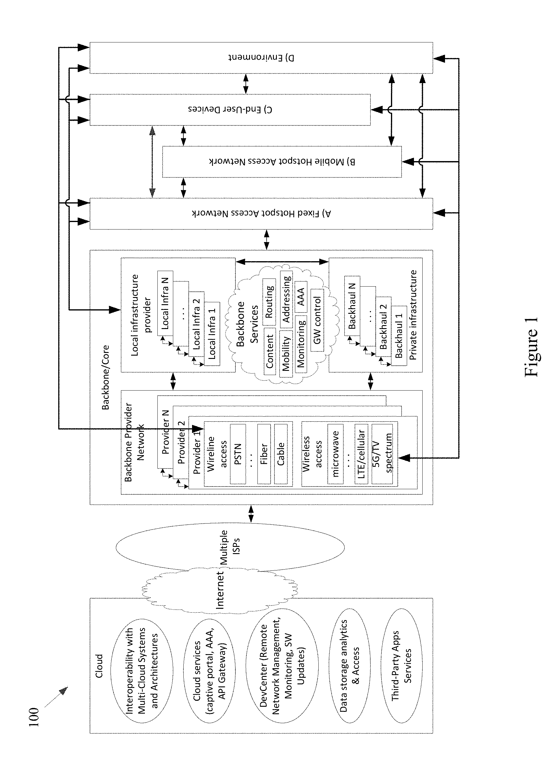
FIG. 1 shows a block diagram of a communication network 100, in accordance with various aspects of this disclosure. Any or all of the functionality discussed herein may be performed by any or all of the example components of the example network 100. Also, the example network 100 may, for example, share any or all characteristics with the other example methods, systems, networks and/or network components 200, 300, 400, 500-570, and 600, discussed herein.
The example network 100, for example, comprises a Cloud that may, for example comprise any of a variety of network level components. The Cloud may, for example, comprise any of a variety of server systems executing applications that monitor and/or control components of the network 100. Such applications may also, for example, manage the collection of information from any of a large array of networked information sources, many examples of which are discussed herein. The Cloud (or a portion thereof) may also be referred to, at times, as an API. For example, Cloud (or a portion thereof) may provide one or more application programming interfaces (APIs) which other devices may use for communicating/interacting with the Cloud.
An example component of the Cloud may, for example, manage interoperability with various multi-cloud systems and architectures. Another example component (e.g., a Cloud service component) may, for example, provide various cloud services (e.g., captive portal services, authentication, authorization, and accounting (AAA) services, API Gateway services, etc.). An additional example component (e.g., a DevCenter component) may, for example, provide network monitoring and/or management functionality, manage the implementation of software updates, etc. A further example component of the Cloud may manage data storage, data analytics, data access, etc. A still further example component of the Cloud may include any of a variety of third-partly applications and services.
The Cloud may, for example, be coupled to the Backbone/Core Infrastructure of the example network 100 via the Internet (e.g., utilizing one or more Internet Service Providers). Though the Internet is provided by example, it should be understood that scope of the present disclosure is not limited thereto.
The Backbone/Core may, for example, comprise any one or more different communication infrastructure components. For example, one or more providers may provide backbone networks or various components thereof. As shown in the example network 100 illustrated in FIG. 1, a Backbone provider may provide wireline access (e.g., PSTN, fiber, cable, etc.). Also for example, a Backbone provider may provide wireless access (e.g., Microwave, LTE/Cellular, 5G/TV Spectrum, etc.).
The Backbone/Core may also, for example, comprise one or more Local Infrastructure Providers. The Backbone/Core may also, for example, comprise a private infrastructure (e.g., run by the network 100 implementer, owner, etc.). The Backbone/Core may, for example, provide any of a variety of Backbone Services (e.g., AAA, Mobility, Monitoring, Addressing, Routing, Content services, Gateway Control services, etc.).
The Backbone/Core Infrastructure may comprise any of a variety of characteristics, non-limiting examples of which are provided herein. For example, the Backbone/Core may be compatible with different wireless or wired technologies for backbone access. The Backbone/Core may also be adaptable to handle public (e.g., municipal, city, campus, etc.) and/or private (e.g., ports, campus, etc.) network infrastructures owned by different local providers, and/or owned by the network implementer or stakeholder. The Backbone/Core may, for example, comprise and/or interface with different Authentication, Authorization, and Accounting (AAA) mechanisms.
The Backbone/Core Infrastructure may, for example, support different modes of operation (e.g., L2 in port implementations, L3 in on-land public transportation implementations, utilizing any one or more of a plurality of different layers of digital IP networking, any combinations thereof, equivalents thereof, etc.) or addressing pools. The Backbone/Core may also for example, be agnostic to the Cloud provider(s) and/or Internet Service Provider(s). Additionally for example, the Backbone/Core may be agnostic to requests coming from any or all subsystems of the network 100 (e.g., Mobile APs or OBUs (On Board Units), Fixed APs or RSUs (Road Side Units), MCs (Mobility Controllers) or LMAs (Local Mobility Anchors) or Network Controllers, etc.) and/or third-party systems.
The Backbone/Core Infrastructure may, for example, comprise the ability to utilize and/or interface with different data storage/processing systems (e.g., MongoDB, MySql, Redis, etc.). The Backbone/Core Infrastructure may further, for example, provide different levels of simultaneous access to the infrastructure, services, data, etc.
The example network 100 may also, for example, comprise a Fixed Hotspot Access Network. Various example characteristics of such a Fixed Hotspot Access Network 200 are shown at FIG. 2. The example network 200 may, for example, share any or all characteristics with the other example methods, systems, networks and/or network components 100, 300, 400, 500-570, and 600, discussed herein n.
In the example network 200, the Fixed APs (e.g., the proprietary APs, the public third party APs, the private third party APs, etc.) may be directly connected to the local infrastructure provider and/or to the wireline/wireless backbone. Also for example, the example network 200 may comprise a mesh between the various APs via wireless technologies. Note, however, that various wired technologies may also be utilized depending on the implementation. As shown, different fixed hotspot access networks can be connected to a same backbone provider, but may also be connected to different respective backbone providers. In an example implementation utilizing wireless technology for backbone access, such an implementation may be relatively fault tolerant. For example, a Fixed AP may utilize wireless communications to the backbone network (e.g., cellular, 3G, LTE, other wide or metropolitan area networks, etc.) if the backhaul infrastructure is down. Also for example, such an implementation may provide for relatively easy installation (e.g., a Fixed AP with no cable power source that can be placed virtually anywhere).
In the example network 200, the same Fixed AP can simultaneously provide access to multiple Fixed APs, Mobile APs (e.g., vehicle OBUs, etc.), devices, user devices, sensors, things, etc. For example, a plurality of mobile hotspot access networks (e.g., OBU-based networks, etc.) may utilize the same Fixed AP. Also for example, the same Fixed AP can provide a plurality of simultaneous accesses to another single unit (e.g., another Fixed AP, Mobile AP, device, etc.), for example utilizing different channels, different radios, etc.).
Note that a plurality of Fixed APs may be utilized for fault-tolerance/fail-recovery purposes. In an example implementation, a Fixed AP and its fail-over AP may both be normally operational (e.g., in a same switch). Also for example, one or more Fixed APs may be placed in the network at various locations in an inactive or monitoring mode, and ready to become operational when needed (e.g., in response to a fault, in response to an emergency services need, in response to a data surge, etc.).
Referring back to FIG. 1, the example Fixed Hotspot Access Network is shown with a wireless communication link to a backbone provider (e.g., to one or more Backbone Providers and/or Local Infrastructure Providers), to a Mobile Hotspot Access Network, to one or more End User Devices, and to the Environment. Also, the example Fixed Hotspot Access Network is shown with a wired communication link to one or more Backbone Providers, to the Mobile Hotspot Access Network, to one or more End User Devices, and to the Environment. The Environment may comprise any of a variety of devices (e.g., in-vehicle networks, devices, and sensors; autonomous vehicle networks, devices, and sensors; maritime (or watercraft) and port networks, devices, and sensors; general controlled-space networks, devices, and sensors; residential networks, devices, and sensors; disaster recovery & emergency networks, devices, and sensors; military and aircraft networks, devices, and sensors; smart city networks, devices, and sensors; event (or venue) networks, devices, and sensors; underwater and underground networks, devices, and sensors; agricultural networks, devices, and sensors; tunnel (auto, subway, train, etc.) networks, devices, and sensors; parking networks, devices, and sensors; security and surveillance networks, devices, and sensors; shipping equipment and container networks, devices, and sensors; environmental control or monitoring networks, devices, and sensors; municipal networks, devices, and sensors; waste management networks, devices, and sensors, road maintenance networks, devices, and sensors, traffic management networks, devices, and sensors; advertising networks, devices and sensors; etc.).
The example network 100 of FIG. 1 also comprises a Mobile Hotspot Access Network. Various example characteristics of such a Mobile Hotspot Access Network 300 are shown at FIG. 3. Note that various fixed network components (e.g., Fixed APs) are also illustrated. The example network 300 may, for example, share any or all characteristics with the other example methods, systems, networks and/or network components 100, 200, 400, 500-570, and 600, discussed herein.
The example network 300 comprises a wide variety of Mobile APs (or hotspots) that provide access to user devices, provide for sensor data collection, provide multi-hop connectivity to other Mobile APs, etc. For example, the example network 300 comprises vehicles from different fleets (e.g., aerial, terrestrial, underground, (under)water, etc.). For example, the example network 300 comprises one or more mass distribution/transportation fleets, one or more mass passenger transportation fleets, private/public shared-user fleets, private vehicles, urban and municipal fleets, maintenance fleets, drones, watercraft (e.g., boats, ships, speedboats, tugboats, barges, etc.), emergency fleets (e.g., police, ambulance, firefighter, etc.), etc.
The example network 300, for example, shows vehicles from different fleets directly connected and/or mesh connected, for example using same or different communication technologies. The example network 300 also shows fleets simultaneously connected to different Fixed APs, which may or may not belong to different respective local infrastructure providers. As a fault-tolerance mechanism, the example network 300 may for example comprise the utilization of long-range wireless communication network (e.g., cellular, 3G, 4G, LTE, etc.) in vehicles if the local network infrastructure is down or otherwise unavailable. A same vehicle (e.g., Mobile AP or OBU) can simultaneously provide access to multiple vehicles, devices, things, etc., for example using a same communication technology (e.g., shared channels and/or different respective channels thereof) and/or using a different respective communication technology for each. Also for example, a same vehicle can provide multiple accesses to another vehicle, device, thing, etc., for example using a same communication technology (e.g., shared channels and/or different respective channels thereof, and/or using a different communication technology).
Additionally, multiple network elements may be connected together to provide for fault-tolerance or fail recovery, increased throughput, or to achieve any or a variety of a client's networking needs, many of examples of which are provided herein. For example, two Mobile APs (or OBUs) may be installed in a same vehicle, etc.
Referring back to FIG. 1, the example Mobile Hotspot Access Network is shown with a wireless communication link to a backbone provider (e.g., to one or more Backbone Providers and/or Local Infrastructure Providers), to a Fixed Hotspot Access Network, to one or more End User Device, and to the Environment (e.g., to any one of more of the sensors or systems discussed herein, any other device or machine, etc.). Though the Mobile Hotspot Access Network is not shown having a wired link to the various other components, there may (at least at times) be such a wired link, at least temporarily.
The example network 100 of FIG. 1 also comprises a set of End-User Devices. Various example end user devices are shown at FIG. 4. Note that various other network components (e.g., Fixed Hotspot Access Networks, Mobile Hotspot Access Network(s), the Backbone/Core, etc.) are also illustrated. The example network 400 may, for example, share any or all characteristics with the other example methods, systems, networks and/or network components 100, 200, 300, 500-570, and 600, discussed herein.
The example network 400 shows various mobile networked devices. Such network devices may comprise end-user devices (e.g., smartphones, tablets, smartwatches, laptop computers, webcams, personal gaming devices, personal navigation devices, personal media devices, personal cameras, health-monitoring devices, personal location devices, monitoring panels, printers, etc.). Such networked devices may also comprise any of a variety of devices operating in the general environment, where such devices might not for example be associated with a particular user (e.g. any or all of the sensor devices discussed herein, vehicle sensors, municipal sensors, fleet sensors road sensors, environmental sensors, security sensors, traffic sensors, waste sensors, meteorological sensors, any of a variety of different types of municipal or enterprise equipment, etc.). Any of such networked devices can be flexibly connected to distinct backbone, fixed hotspot access networks, mobile hotspot access networks, etc., using the same or different wired/wireless technologies.
A mobile device may, for example, operate as an AP to provide simultaneous access to multiple devices/things, which may then form ad hoc networks, interconnecting devices ultimately connected to distinct backbone networks, fixed hotspot, and/or mobile hotspot access networks. Devices (e.g., any or all of the devices or network nodes discussed herein) may, for example, have redundant technologies to access distinct backbone, fixed hotspot, and/or mobile hotspot access networks, for example for fault-tolerance and/or load-balancing purposes (e.g., utilizing multiple SIM cards, etc.). A device may also, for example, simultaneously access distinct backbone, fixed hotspot access networks, and/or mobile hotspot access networks, belonging to the same provider or to different respective providers. Additionally for example, a device can provide multiple accesses to another device/thing (e.g., via different channels, radios, etc.).
Referring back to FIG. 1, the example End-User Devices are shown with a wireless communication link to a backbone provider (e.g., to one or more Backbone Providers and/or Local Infrastructure Providers), to a Fixed Hotspot Access Network, to a Mobile Hotspot Access Network, and to the Environment. Also for example, the example End-User Devices are shown with a wired communication link to a backbone provider, to a Fixed Hotspot Access Network, to a Mobile Hotspot Access Network, and to the Environment.
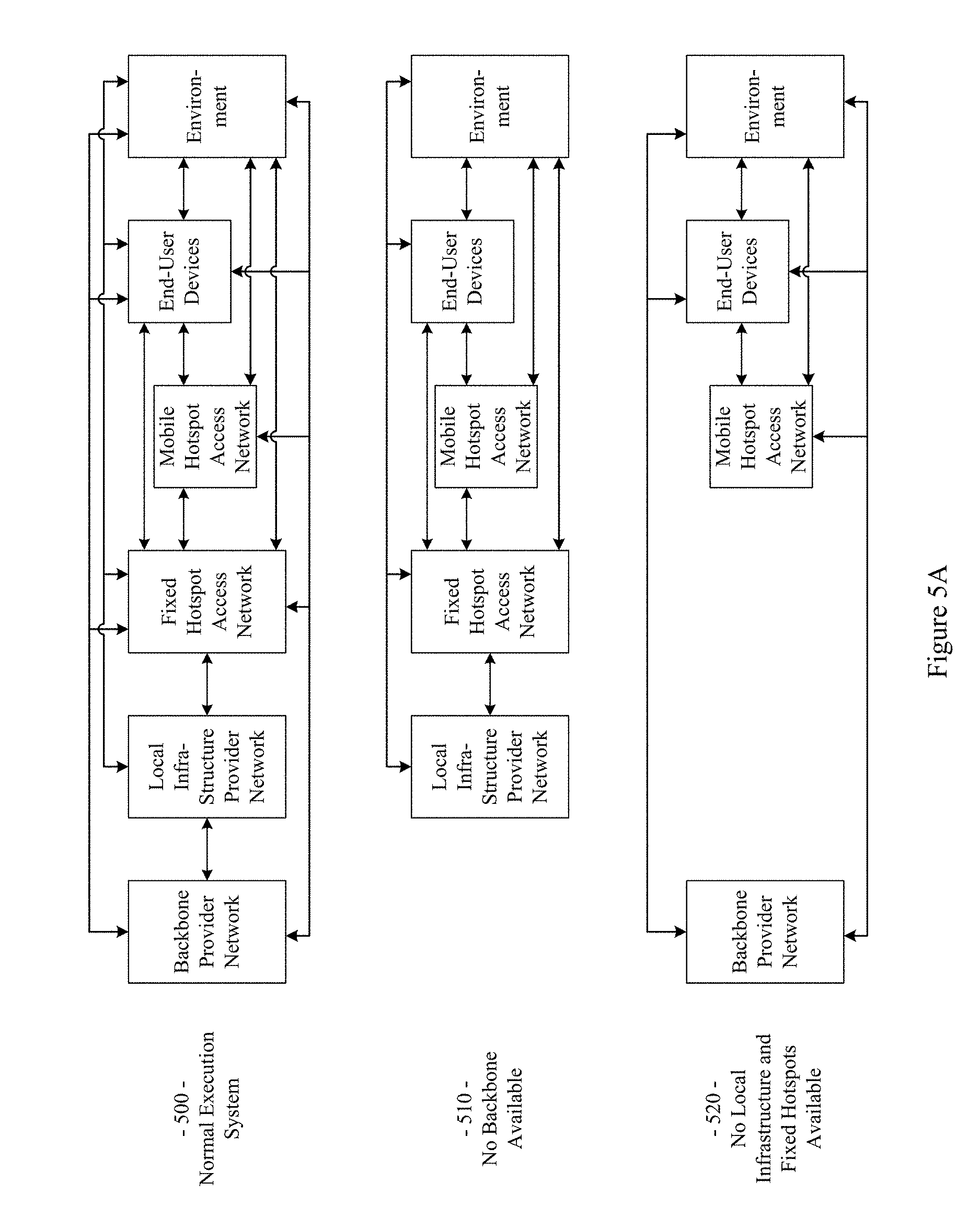
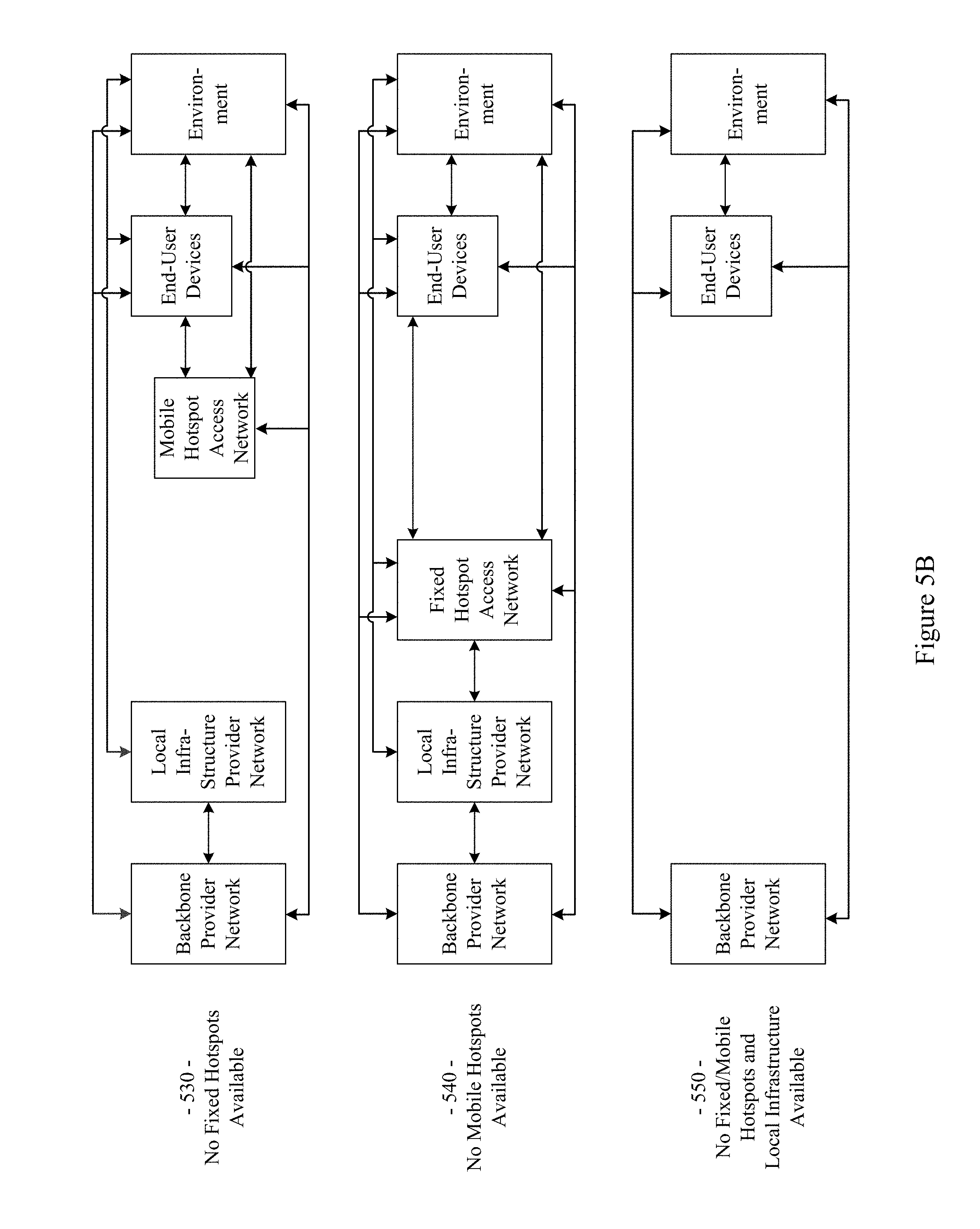
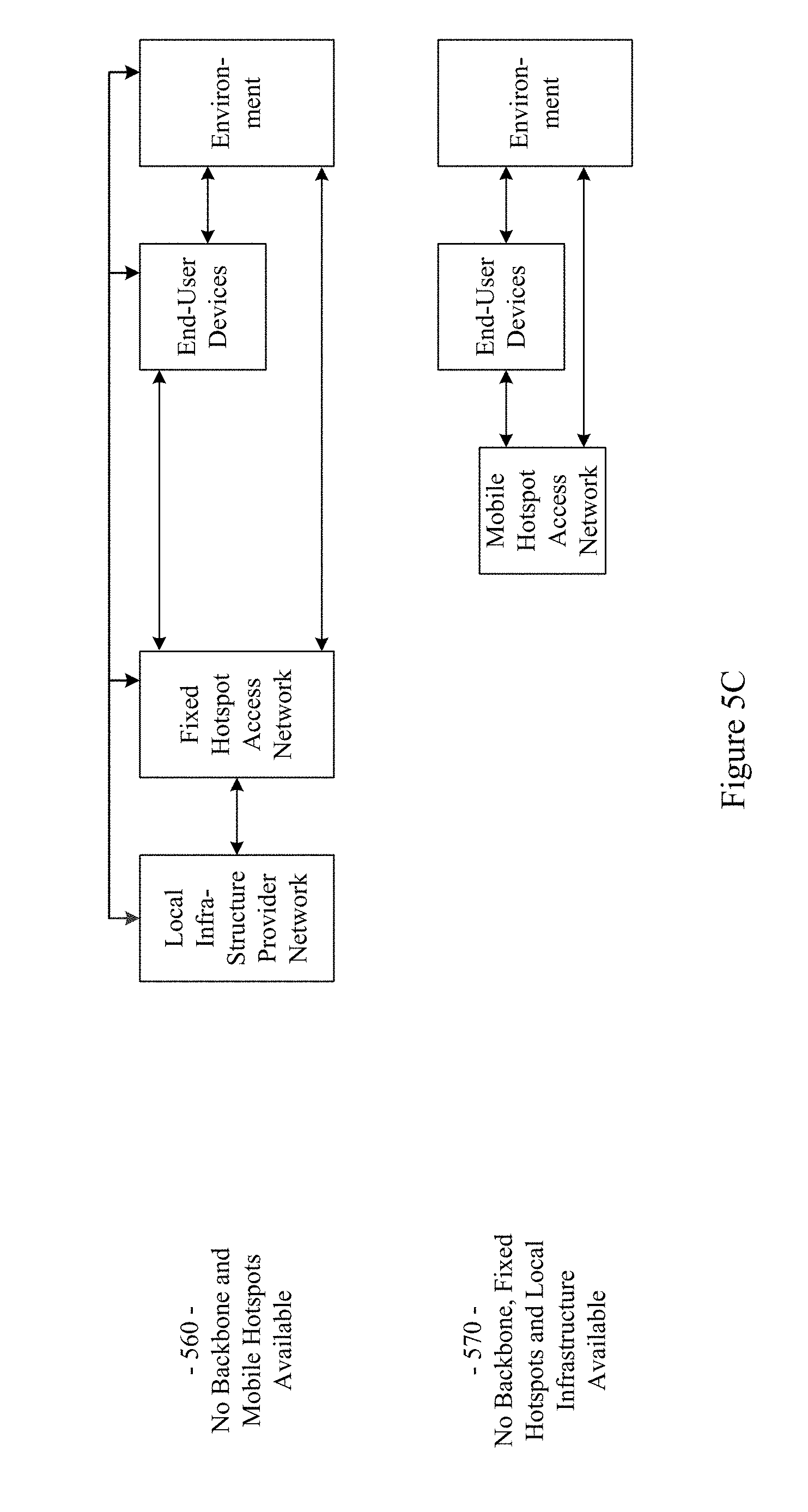
The example network 100 illustrated in FIG. 1 has a flexible architecture that is adaptable at implementation time (e.g., for different use cases) and/or adaptable in real-time, for example as network components enter and leave service. FIGS. 5A-5C illustrate such flexibility by providing example modes (or configurations). The example networks 500-570 may, for example, share any or all characteristics with the other example methods, systems, networks and/or network components 100, 200, 300, 400, and 600, discussed herein. For example and without limitation, any or all of the communication links (e.g., wired links, wireless links, etc.) shown in the example networks 500-570 are generally analogous to similarly positioned communication links shown in the example network 100 of FIG. 1.
For example, various aspects of this disclosure provide communication network architectures, systems, and methods for supporting a dynamically configurable communication network comprising a complex array of both static and moving communication nodes (e.g., the Internet of moving things). For example, a communication network implemented in accordance with various aspects of the present disclosure may operate in one of a plurality of modalities comprising various fixed nodes, mobile nodes, and/or a combination thereof, which are selectable to yield any of a variety of system goals (e.g., increased throughput, reduced latency and packet loss, increased availability and robustness of the system, extra redundancy, increased responsiveness, increased security in the transmission of data and/or control packets, reduced number of configuration changes by incorporating smart thresholds (e.g., change of technology, change of certificate, change of IP, etc.), providing connectivity in dead zones or zones with difficult access, reducing the costs for maintenance and accessing the equipment for updating/upgrading, etc.). At least some of such modalities may, for example, be entirely comprised of fixed-position nodes, at least temporarily if not permanently.
For illustrative simplicity, many of the example aspects shown in the example system or network 100 of FIG. 1 (and other Figures herein) are omitted from FIGS. 5A-5C, but may be present. For example, the Cloud, Internet, and ISP aspects shown in FIG. 1 and in other Figures are not explicitly shown in FIGS. 5A-5C, but may be present in any of the example configurations (e.g., as part of the backbone provider network or coupled thereto, as part of the local infrastructure provider network or coupled thereto, etc.).
For example, the first example mode 500 is presented as a normal execution mode, for example a mode (or configuration) in which all of the components discussed herein are present. For example, the communication system in the first example mode 500 comprises a backbone provider network, a local infrastructure provider network, a fixed hotspot access network, a mobile hotspot access network, end-user devices, and environment devices.
As shown in FIG. 5A, and in FIG. 1 in more detail, the backbone provider network may be communicatively coupled to any or all of the other elements present in the first example mode 500 (or configuration) via one or more wired (or tethered) links. For example, the backbone provider network may be communicatively coupled to the local infrastructure provider network (or any component thereof), fixed hotspot access network (or any component thereof), the end-user devices, and/or environment devices via a wired link. Note that such a wired coupling may be temporary. Also note that in various example configurations, the backbone provider network may also, at least temporarily, be communicatively coupled to the mobile hotspot access network (or any component thereof) via one or more wired (or tethered) links.
Also shown in FIG. 5A, and in FIG. 1 in more detail, the backbone provider network may be communicatively coupled to any or all of the other elements present in the first example mode 500 (or configuration) via one or more wireless links (e.g., RF link, non-tethered optical link, etc.). For example, the backbone provider network may be communicatively coupled to the fixed hotspot access network (or any component thereof), the mobile hotspot access network (or any component thereof), the end-user devices, and/or environment devices via one or more wireless links. Also note that in various example configurations, the backbone provider network may also be communicatively coupled to the local infrastructure provider network via one or more wireless (or non-tethered) links.
Though not shown in the first example mode 500 (or any of the example modes of FIGS. 5A-5C), one or more servers may be communicatively coupled to the backbone provider network and/or the local infrastructure network. FIG. 1 provides an example of cloud servers being communicatively coupled to the backbone provider network via the Internet.
As additionally shown in FIG. 5A, and in FIG. 1 in more detail, the local infrastructure provider network may be communicatively coupled to any or all of the other elements present in the first example mode 500 (or configuration) via one or more wired (or tethered) links. For example, the local infrastructure provider network may be communicatively coupled to the backbone provider network (or any component thereof), fixed hotspot access network (or any component thereof), the end-user devices, and/or environment devices via one or more wired links. Note that such a wired coupling may be temporary. Also note that in various example configurations, the local infrastructure provider network may also, at least temporarily, be communicatively coupled to the mobile hotspot access network (or any component thereof) via one or more wired (or tethered) links.
Also, though not explicitly shown, the local infrastructure provider network may be communicatively coupled to any or all of the other elements present in the first example mode 500 (or configuration) via one or more wireless links (e.g., RF link, non-tethered optical link, etc.). For example, the local infrastructure provider network may be communicatively coupled to the backbone provider network (or any component thereof), the fixed hotspot access network (or any component thereof), the mobile hotspot access network (or any component thereof), the end-user devices, and/or environment devices via one or more wireless links. Note that the communication link shown in the first example mode 500 of FIG. 5A between the local infrastructure provider network and the fixed hotspot access network may be wired and/or wireless.
The fixed hotspot access network is also shown in the first example mode 500 to be communicatively coupled to the mobile hotspot access network, the end-user devices, and/or environment devices via one or more wireless links. Many examples of such wireless coupling are provided herein. Additionally, the mobile hotspot access network is further shown in the first example mode 500 to be communicatively coupled to the end-user devices and/or environment devices via one or more wireless links. Many examples of such wireless coupling are provided herein. Further, the end-user devices are also shown in the first example mode 500 to be communicatively coupled to the environment devices via one or more wireless links. Many examples of such wireless coupling are provided herein. Note that in various example implementations any of such wireless links may instead (or in addition) comprise a wired (or tethered) link.
In the first example mode 500 (e.g., the normal mode), information (or data) may be communicated between an end-user device and a server (e.g., a computer system) via the mobile hotspot access network, the fixed hotspot access network, the local infrastructure provider network, and/or the backbone provider network. As will be seen in the various example modes presented herein, such communication may flexibly occur between an end-user device and a server via any of a variety of different communication pathways, for example depending on the availability of a network, depending on bandwidth utilization goals, depending on communication priority, depending on communication time (or latency) and/or reliability constraints, depending on cost, etc. For example, information communicated between an end user device and a server may be communicated via the fixed hotspot access network, the local infrastructure provider network, and/or the backbone provider network (e.g., skipping the mobile hotspot access network). Also for example, information communicated between an end user device and a server may be communicated via the backbone provider network (e.g., skipping the mobile hotspot access network, fixed hotspot access network, and/or local infrastructure provider network).
Similarly, in the first example mode 500 (e.g., the normal mode), information (or data) may be communicated between an environment device and a server via the mobile hotspot access network, the fixed hotspot access network, the local infrastructure provider network, and/or the backbone provider network. Also for example, an environment device may communicate with or through an end-user device (e.g., instead of or in addition to the mobile hotspot access network). As will be seen in the various example modes presented herein, such communication may flexibly occur between an environment device and a server (e.g., communicatively coupled to the local infrastructure provider network and/or backbone provider network) via any of a variety of different communication pathways, for example depending on the availability of a network, depending on bandwidth utilization goals, depending on communication priority, depending on communication time (or latency) and/or reliability constraints, depending on cost, etc.
For example, information communicated between an environment device and a server may be communicated via the fixed hotspot access network, the local infrastructure provider network, and/or the backbone provider network (e.g., skipping the mobile hotspot access network). Also for example, information communicated between an environment device and a server may be communicated via the backbone provider network (e.g., skipping the mobile hotspot access network, fixed hotspot access network, and/or local infrastructure provider network). Additionally for example, information communicated between an environment device and a server may be communicated via the local infrastructure provider network (e.g., skipping the mobile hotspot access network and/or fixed hotspot access network).
As discussed herein, the example networks presented herein are adaptively configurable to operate in any of a variety of different modes (or configurations). Such adaptive configuration may occur at initial installation and/or during subsequent controlled network evolution (e.g., adding or removing any or all of the network components discussed herein, expanding or removing network capacity, adding or removing coverage areas, adding or removing services, etc.). Such adaptive configuration may also occur in real-time, for example in response to real-time changes in network conditions (e.g., networks or components thereof being available or not based on vehicle or user-device movement, network or component failure, network or component replacement or augmentation activity, network overloading, etc.). The following example modes are presented to illustrate characteristics of various modes in which a communication system may operate in accordance with various aspects of the present disclosure. The following example modes will generally be discussed in relation to the first example mode 500 (e.g., the normal execution mode). Note that such example modes are merely illustrative and not limiting.
The second example mode (or configuration) 510 (e.g., a no backbone available mode) may, for example, share any or all characteristics with the first example mode 500, albeit without the backbone provider network and communication links therewith. For example, the communication system in the second example mode 510 comprises a local infrastructure provider network, a fixed hotspot access network, a mobile hotspot access network, end-user devices, and environment devices.
As shown in FIG. 5A, and in FIG. 1 in more detail, the local infrastructure provider network may be communicatively coupled to any or all of the other elements present in the second example mode 510 (or configuration) via one or more wired (or tethered) links. For example, the local infrastructure provider network may be communicatively coupled to the fixed hotspot access network (or any component thereof), the end-user devices, and/or environment devices via one or more wired links. Note that such a wired coupling may be temporary. Also note that in various example configurations, the local infrastructure provider network may also, at least temporarily, be communicatively coupled to the mobile hotspot access network (or any component thereof) via one or more wired (or tethered) links.
Also, though not explicitly shown, the local infrastructure provider network may be communicatively coupled to any or all of the other elements present in the second example mode 510 (or configuration) via one or more wireless links (e.g., RF link, non-tethered optical link, etc.). For example, the local infrastructure provider network may be communicatively coupled to the fixed hotspot access network (or any component thereof), the mobile hotspot access network (or any component thereof), the end-user devices, and/or environment devices via one or more wireless links. Note that the communication link(s) shown in the second example mode 510 of FIG. 5A between the local infrastructure provider network and the fixed hotspot access network may be wired and/or wireless.
The fixed hotspot access network is also shown in the second example mode 510 to be communicatively coupled to the mobile hotspot access network, the end-user devices, and/or environment devices via one or more wireless links. Many examples of such wireless coupling are provided herein. Additionally, the mobile hotspot access network is further shown in the second example mode 510 to be communicatively coupled to the end-user devices and/or environment devices via one or more wireless links. Many examples of such wireless coupling are provided herein. Further, the end-user devices are also shown in the second example mode 510 to be communicatively coupled to the environment devices via one or more wireless links. Many examples of such wireless coupling are provided herein. Note that in various example implementations any of such wireless links may instead (or in addition) comprise a wired (or tethered) link.
In the second example mode 510 (e.g., the no backbone available mode), information (or data) may be communicated between an end-user device and a server (e.g., a computer, etc.) via the mobile hotspot access network, the fixed hotspot access network, and/or the local infrastructure provider network. As will be seen in the various example modes presented herein, such communication may flexibly occur between an end-user device and a server via any of a variety of different communication pathways, for example depending on the availability of a network, depending on bandwidth utilization goals, depending on communication priority, depending on communication time (or latency) and/or reliability constraints, depending on cost, etc. For example, information communicated between an end user device and a server may be communicated via the fixed hotspot access network and/or the local infrastructure provider network (e.g., skipping the mobile hotspot access network). Also for example, information communicated between an end user device and a server may be communicated via the local infrastructure provider network (e.g., skipping the mobile hotspot access network and/or fixed hotspot access network).
Similarly, in the second example mode 510 (e.g., the no backbone available mode), information (or data) may be communicated between an environment device and a server via the mobile hotspot access network, the fixed hotspot access network, and/or the local infrastructure provider network. Also for example, an environment device may communicate with or through an end-user device (e.g., instead of or in addition to the mobile hotspot access network). As will be seen in the various example modes presented herein, such communication may flexibly occur between an environment device and a server (e.g., communicatively coupled to the local infrastructure provider network) via any of a variety of different communication pathways, for example depending on the availability of a network, depending on bandwidth utilization goals, depending on communication priority, depending on communication time (or latency) and/or reliability constraints, depending on cost, etc.
For example, information communicated between an environment device and a server may be communicated via the fixed hotspot access network and/or the local infrastructure provider network (e.g., skipping the mobile hotspot access network). Also for example, information communicated between an environment device and a server may be communicated via the local infrastructure provider network (e.g., skipping the mobile hotspot access network and/or fixed hotspot access network).
The second example mode 510 may be utilized for any of a variety of reasons, non-limiting examples of which are provided herein. For example, due to security and/or privacy goals, the second example mode 510 may be utilized so that communication access to the public Cloud systems, the Internet in general, etc., is not allowed. For example, all network control and management functions may be within the local infrastructure provider network (e.g., wired local network, etc.) and/or the fixed access point network.
In an example implementation, the communication system might be totally owned, operated and/or controlled by a local port authority. No extra expenses associated with cellular connections need be spent. For example, cellular connection capability (e.g., in Mobile APs, Fixed APs, end user devices, environment devices, etc.) need not be provided. Note also that the second example mode 510 may be utilized in a scenario in which the backbone provider network is normally available but is currently unavailable (e.g., due to server failure, due to communication link failure, due to power outage, due to a temporary denial of service, etc.).
The third example mode (or configuration) 520 (e.g., a no local infrastructure and fixed hotspots available mode) may, for example, share any or all characteristics with the first example mode 500, albeit without the local infrastructure provider network, the fixed hotspot access network, and communication links therewith. For example, the communication system in the third example mode 520 comprises a backbone provider network, a mobile hotspot access network, end-user devices, and environment devices.
As shown in FIG. 5A, and in FIG. 1 in more detail, the backbone provider network may be communicatively coupled to any or all of the other elements present in the third example mode 520 (or configuration) via one or more wired (or tethered) links. For example, the backbone provider network may be communicatively coupled to the end-user devices and/or environment devices via one or more wired links. Note that such a wired coupling may be temporary. Also note that in various example configurations, the backbone provider network may also, at least temporarily, be communicatively coupled to the mobile hotspot access network (or any component thereof) via one or more wired (or tethered) links.
Also shown in FIG. 5A, and in FIG. 1 in more detail, the backbone provider network may be communicatively coupled to any or all of the other elements present in the third example mode 520 (or configuration) via one or more wireless links (e.g., RF link, non-tethered optical link, etc.). For example, the backbone provider network may be communicatively coupled to the mobile hotspot access network (or any component thereof), the end-user devices, and/or environment devices via one or more wireless links.
The mobile hotspot access network is further shown in the third example mode 520 to be communicatively coupled to the end-user devices and/or environment devices via one or more wireless links. Many examples of such wireless coupling are provided herein. Further, the end-user devices are also shown in the third example mode 520 to be communicatively coupled to the environment devices via one or more wireless links. Many examples of such wireless coupling are provided herein. Note that in various example implementations any of such wireless links may instead (or in addition) comprise a wired (or tethered) link.
In the third example mode 520 (e.g., the no local infrastructure and fixed hotspots available mode), information (or data) may be communicated between an end-user device and a server (e.g., a computer, etc.) via the mobile hotspot access network and/or the backbone provider network. As will be seen in the various example modes presented herein, such communication may flexibly occur between an end-user device and a server via any of a variety of different communication pathways, for example depending on the availability of a network, depending on bandwidth utilization goals, depending on communication priority, depending on communication time (or latency) and/or reliability constraints, depending on cost, etc. For example, information communicated between an end user device and a server may be communicated via the backbone provider network (e.g., skipping the mobile hotspot access network).
Similarly, in the third example mode 520 (e.g., the no local infrastructure and fixed hotspots available mode), information (or data) may be communicated between an environment device and a server via the mobile hotspot access network and/or the backbone provider network. Also for example, an environment device may communicate with or through an end-user device (e.g., instead of or in addition to the mobile hotspot access network). As will be seen in the various example modes presented herein, such communication may flexibly occur between an environment device and a server (e.g., communicatively coupled to the backbone provider network) via any of a variety of different communication pathways, for example depending on the availability of a network, depending on bandwidth utilization goals, depending on communication priority, depending on communication time (or latency) and/or reliability constraints, depending on cost, etc. For example, information communicated between an environment device and a server may be communicated via the backbone provider network (e.g., skipping the mobile hotspot access network).
In the third example mode 520, all control/management functions may for example be implemented within the Cloud. For example, since the mobile hotspot access network does not have a communication link via a fixed hotspot access network, the Mobile APs may utilize a direct connection (e.g., a cellular connection) with the backbone provider network (or Cloud). If a Mobile AP does not have such capability, the Mobile AP may also, for example, utilize data access provided by the end-user devices communicatively coupled thereto (e.g., leveraging the data plans of the end-user devices).
The third example mode 520 may be utilized for any of a variety of reasons, non-limiting examples of which are provided herein. In an example implementation, the third example mode 520 may be utilized in an early stage of a larger deployment, for example deployment that will grow into another mode (e.g., the example first mode 500, example fourth mode 530, etc.) as more communication system equipment is installed. Note also that the third example mode 520 may be utilized in a scenario in which the local infrastructure provider network and fixed hotspot access network are normally available but are currently unavailable (e.g., due to equipment failure, due to communication link failure, due to power outage, due to a temporary denial of service, etc.).
The fourth example mode (or configuration) 530 (e.g., a no fixed hotspots available mode) may, for example, share any or all characteristics with the first example mode 500, albeit without the fixed hotspot access network and communication links therewith. For example, the communication system in the fourth example mode 530 comprises a backbone provider network, a local infrastructure provider network, a mobile hotspot access network, end-user devices, and environment devices.
As shown in FIG. 5B, and in FIG. 1 in more detail, the backbone provider network may be communicatively coupled to any or all of the other elements present in the fourth example mode 530 (or configuration) via one or more wired (or tethered) links. For example, the backbone provider network may be communicatively coupled to the local infrastructure provider network (or any component thereof), the end-user devices, and/or environment devices via one or more wired links. Note that such a wired coupling may be temporary. Also note that in various example configurations, the backbone provider network may also, at least temporarily, be communicatively coupled to the mobile hotspot access network (or any component thereof) via one or more wired (or tethered) links.
Also shown in FIG. 5B, and in FIG. 1 in more detail, the backbone provider network may be communicatively coupled to any or all of the other elements present in the fourth example mode 530 (or configuration) via one or more wireless links (e.g., RF link, non-tethered optical link, etc.). For example, the backbone provider network may be communicatively coupled to the mobile hotspot access network (or any component thereof), the end-user devices, and/or environment devices via one or more wireless links. Also note that in various example configurations, the backbone provider network may also be communicatively coupled to the local infrastructure provider network via one or more wireless (or non-tethered) links.
As additionally shown in FIG. 5B, and in FIG. 1 in more detail, the local infrastructure provider network may be communicatively coupled to any or all of the other elements present in the fourth example mode 530 (or configuration) via one or more wired (or tethered) links. For example, the local infrastructure provider network may be communicatively coupled to the backbone provider network (or any component thereof), the end-user devices, and/or environment devices via one or more wired links. Note that such a wired coupling may be temporary. Also note that in various example configurations, the local infrastructure provider network may also, at least temporarily, be communicatively coupled to the mobile hotspot access network (or any component thereof) via one or more wired (or tethered) links.
Also, though not explicitly shown, the local infrastructure provider network may be communicatively coupled to any or all of the other elements present in the fourth example mode 530 (or configuration) via one or more wireless links (e.g., RF link, non-tethered optical link, etc.). For example, the local infrastructure provider network may be communicatively coupled to the backbone provider network (or any component thereof), the mobile hotspot access network (or any component thereof), the end-user devices, and/or environment devices via one or more wireless links.
The mobile hotspot access network is further shown in the fourth example mode 530 to be communicatively coupled to the end-user devices and/or environment devices via one or more wireless links. Many examples of such wireless coupling are provided herein. Further, the end-user devices are also shown in the fourth example mode 530 to be communicatively coupled to the environment devices via one or more wireless links. Many examples of such wireless coupling are provided herein.
In the fourth example mode 530 (e.g., the no fixed hotspots mode), information (or data) may be communicated between an end-user device and a server via the mobile hotspot access network, the local infrastructure provider network, and/or the backbone provider network. As will be seen in the various example modes presented herein, such communication may flexibly occur between an end-user device and a server via any of a variety of different communication pathways, for example depending on the availability of a network, depending on bandwidth utilization goals, depending on communication priority, depending on communication time (or latency) and/or reliability constraints, depending on cost, etc. For example, information communicated between an end user device and a server may be communicated via the local infrastructure provider network and/or the backbone provider network (e.g., skipping the mobile hotspot access network). Also for example, information communicated between an end user device and a server may be communicated via the backbone provider network (e.g., skipping the mobile hotspot access network and/or local infrastructure provider network).
Similarly, in the fourth example mode 530 (e.g., the no fixed hotspots available mode), information (or data) may be communicated between an environment device and a server via the mobile hotspot access network, the local infrastructure provider network, and/or the backbone provider network. Also for example, an environment device may communicate with or through an end-user device (e.g., instead of or in addition to the mobile hotspot access network). As will be seen in the various example modes presented herein, such communication may flexibly occur between an environment device and a server (e.g., communicatively coupled to the local infrastructure provider network and/or backbone provider network) via any of a variety of different communication pathways, for example depending on the availability of a network, depending on bandwidth utilization goals, depending on communication priority, depending on communication time (or latency) and/or reliability constraints, depending on cost, etc.
For example, information communicated between an environment device and a server may be communicated via the local infrastructure provider network and/or the backbone provider network (e.g., skipping the mobile hotspot access network). Also for example, information communicated between an environment device and a server may be communicated via the backbone provider network (e.g., skipping the mobile hotspot access network and/or local infrastructure provider network). Additionally for example, information communicated between an environment device and a server may be communicated via the local infrastructure provider network (e.g., skipping the mobile hotspot access network and/or backbone provider network).
In the fourth example mode 530, in an example implementation, some of the control/management functions may for example be implemented within the local backbone provider network (e.g., within a client premises). For example, communication to the local infrastructure provider may be performed through the backbone provider network (or Cloud). Note that in a scenario in which there is a direct communication pathway between the local infrastructure provider network and the mobile hotspot access network, such communication pathway may be utilized.
For example, since the mobile hotspot access network does not have a communication link via a fixed hotspot access network, the Mobile APs may utilize a direct connection (e.g., a cellular connection) with the backbone provider network (or Cloud). If a Mobile AP does not have such capability, the Mobile AP may also, for example, utilize data access provided by the end-user devices communicatively coupled thereto (e.g., leveraging the data plans of the end-user devices).
The fourth example mode 530 may be utilized for any of a variety of reasons, non-limiting examples of which are provided herein. In an example implementation, the fourth example mode 530 may be utilized in an early stage of a larger deployment, for example a deployment that will grow into another mode (e.g., the example first mode 500, etc.) as more communication system equipment is installed. The fourth example mode 530 may, for example, be utilized in a scenario in which there is no fiber (or other) connection available for Fixed APs (e.g., in a maritime scenario, in a plantation scenario, etc.), or in which a Fixed AP is difficult to access or connect. For example, one or more Mobile APs of the mobile hotspot access network may be used as gateways to reach the Cloud. The fourth example mode 530 may also, for example, be utilized when a vehicle fleet and/or the Mobile APs associated therewith are owned by a first entity and the Fixed APs are owned by another entity, and there is no present agreement for communication between the Mobile APs and the Fixed APs. Note also that the fourth example mode 530 may be utilized in a scenario in which the fixed hotspot access network is normally available but are currently unavailable (e.g., due to equipment failure, due to communication link failure, due to power outage, due to a temporary denial of service, etc.).
The fifth example mode (or configuration) 540 (e.g., a no mobile hotspots available mode) may, for example, share any or all characteristics with the first example mode 500, albeit without the mobile hotspot access network and communication links therewith. For example, the communication system in the fifth example mode 540 comprises a backbone provider network, a local infrastructure provider network, a fixed hotspot access network, end-user devices, and environment devices.
As shown in FIG. 5B, and in FIG. 1 in more detail, the backbone provider network may be communicatively coupled to any or all of the other elements present in the fifth example mode 540 (or configuration) via one or more wired (or tethered) links. For example, the backbone provider network may be communicatively coupled to the local infrastructure provider network (or any component thereof), fixed hotspot access network (or any component thereof), the end-user devices, and/or environment devices via one or more wired links. Note that such a wired coupling may be temporary.
Also shown in FIG. 5B, and in FIG. 1 in more detail, the backbone provider network may be communicatively coupled to any or all of the other elements present in the fifth example mode 540 (or configuration) via one or more wireless links (e.g., RF link, non-tethered optical link, etc.). For example, the backbone provider network may be communicatively coupled to the fixed hotspot access network (or any component thereof), the end-user devices, and/or environment devices via one or more wireless links. Also note that in various example configurations, the backbone provider network may also be communicatively coupled to the local infrastructure provider network via one or more wireless (or non-tethered) links.
As additionally shown in FIG. 5B, and in FIG. 1 in more detail, the local infrastructure provider network may be communicatively coupled to any or all of the other elements present in the fifth example mode 540 (or configuration) via one or more wired (or tethered) links. For example, the local infrastructure provider network may be communicatively coupled to the backbone provider network (or any component thereof), fixed hotspot access network (or any component thereof), the end-user devices, and/or environment devices via one or more wired links. Note that such a wired coupling may be temporary. Also note that in various example configurations, the local infrastructure provider network may also, at least temporarily, be communicatively coupled to the mobile hotspot access network (or any component thereof) via one or more wired (or tethered) links.
Also, though not explicitly shown, the local infrastructure provider network may be communicatively coupled to any or all of the other elements present in the fifth example mode 540 (or configuration) via one or more wireless links (e.g., RF link, non-tethered optical link, etc.). For example, the local infrastructure provider network may be communicatively coupled to the backbone provider network, the fixed hotspot access network (or any component thereof), the end-user devices, and/or environment devices via one or more wireless links. Note that the communication link(s) shown in the fifth example mode 540 of FIG. 5B between the local infrastructure provider network and the fixed hotspot access network may be wired and/or wireless.
The fixed hotspot access network is also shown in the fifth example mode 540 to be communicatively coupled to the end-user devices and/or environment devices via one or more wireless links. Many examples of such wireless coupling are provided herein. Further, the end-user devices are also shown in the fifth example mode 540 to be communicatively coupled to the environment devices via one or more wireless links. Many examples of such wireless coupling are provided herein.
In the fifth example mode 540 (e.g., the no mobile hotspots available mode), information (or data) may be communicated between an end-user device and a server via the fixed hotspot access network, the local infrastructure provider network, and/or the backbone provider network. As will be seen in the various example modes presented herein, such communication may flexibly occur between an end-user device and a server via any of a variety of different communication pathways, for example depending on the availability of a network, depending on bandwidth utilization goals, depending on communication priority, depending on communication time (or latency) and/or reliability constraints, depending on cost, etc. For example, information communicated between an end user device and a server may be communicated via the local infrastructure provider network, and/or the backbone provider network (e.g., skipping the fixed hotspot access network). Also for example, information communicated between an end user device and a server may be communicated via the backbone provider network (e.g., skipping the fixed hotspot access network and/or local infrastructure provider network).
Similarly, in the fifth example mode 540 (e.g., the no mobile hotspots available mode), information (or data) may be communicated between an environment device and a server via the fixed hotspot access network, the local infrastructure provider network, and/or the backbone provider network. Also for example, an environment device may communicate with or through an end-user device (e.g., instead of or in addition to the fixed hotspot access network). As will be seen in the various example modes presented herein, such communication may flexibly occur between an environment device and a server (e.g., communicatively coupled to the local infrastructure provider network and/or backbone provider network) via any of a variety of different communication pathways, for example depending on the availability of a network, depending on bandwidth utilization goals, depending on communication priority, depending on communication time (or latency) and/or reliability constraints, depending on cost, etc.
For example, information communicated between an environment device and a server may be communicated via the local infrastructure provider network and/or the backbone provider network (e.g., skipping the fixed hotspot access network). Also for example, information communicated between an environment device and a server may be communicated via the backbone provider network (e.g., skipping the fixed hotspot access network and/or local infrastructure provider network). Additionally for example, information communicated between an environment device and a server may be communicated via the local infrastructure provider network (e.g., skipping the fixed hotspot access network and/or the backbone provider network).
In the fifth example mode 540, in an example implementation, the end-user devices and environment devices may communicate directly to Fixed APs (e.g., utilizing Ethernet, Wi-Fi, etc.). Also for example, the end-user devices and/or environment devices may communicate directly with the backbone provider network (e.g., utilizing cellular connections, etc.).
The fifth example mode 540 may be utilized for any of a variety of reasons, non-limiting examples of which are provided herein. In an example implementation in which end-user devices and/or environment devices may communicate directly with Fixed APs, such communication may be utilized instead of Mobile AP communication. For example, the fixed hotspot access network might provide coverage for all desired areas.
Note also that the fifth example mode 540 may be utilized in a scenario in which the fixed hotspot access network is normally available but is currently unavailable (e.g., due to equipment failure, due to communication link failure, due to power outage, due to a temporary denial of service, etc.).
The sixth example mode (or configuration) 550 (e.g., the no fixed/mobile hotspots and local infrastructure available mode) may, for example, share any or all characteristics with the first example mode 500, albeit without the local infrastructure provider network, fixed hotspot access network, mobile hotspot access network, and communication links therewith. For example, the communication system in the sixth example mode 550 comprises a backbone provider network, end-user devices, and environment devices.
As shown in FIG. 5B, and in FIG. 1 in more detail, the backbone provider network may be communicatively coupled to any or all of the other elements present in the sixth example mode 550 (or configuration) via one or more wired (or tethered) links. For example, the backbone provider network may be communicatively coupled to the end-user devices and/or environment devices via one or more wired links. Note that such a wired coupling may be temporary.
Also shown in FIG. 5B, and in FIG. 1 in more detail, the backbone provider network may be communicatively coupled to any or all of the other elements present in the sixth example mode 550 (or configuration) via one or more wireless links (e.g., RF link, non-tethered optical link, etc.). For example, the backbone provider network may be communicatively coupled to the end-user devices and/or environment devices via one or more wireless links.
The end-user devices are also shown in the sixth example mode 550 to be communicatively coupled to the environment devices via one or more wireless links. Many examples of such wireless coupling are provided herein.
In the sixth example mode 550 (e.g., the no fixed/mobile hotspots and local infrastructure available mode), information (or data) may be communicated between an end-user device and a server via the backbone provider network. Similarly, in the sixth example mode 550 (e.g., the no fixed/mobile hotspots and local infrastructure mode), information (or data) may be communicated between an environment device and a server via the backbone provider network. Also for example, an environment device may communicate with or through an end-user device (e.g., instead of or in addition to the mobile hotspot access network).
The sixth example mode 550 may be utilized for any of a variety of reasons, non-limiting examples of which are provided herein. In an example implementation, for example in which an end-user has not yet subscribed to the communication system, the end-user device may subscribe to the system through a Cloud application and by communicating directly with the backbone provider network (e.g., via cellular link, etc.). The sixth example mode 550 may also, for example, be utilized in rural areas in which Mobile AP presence is sparse, Fixed AP installation is difficult or impractical, etc.
Note also that the sixth example mode 550 may be utilized in a scenario in which the infrastructure provider network, fixed hotspot access network, and/or mobile hotspot access network are normally available but are currently unavailable (e.g., due to equipment failure, due to communication link failure, due to power outage, due to a temporary denial of service, etc.).
The seventh example mode (or configuration) 560 (e.g., the no backbone and mobile hotspots available mode) may, for example, share any or all characteristics with the first example mode 500, albeit without the backbone provider network, mobile hotspot access network, and communication links therewith. For example, the communication system in the seventh example mode 560 comprises a local infrastructure provider network, fixed hotspot access network, end-user devices, and environment devices.
As shown in FIG. 5C, and in FIG. 1 in more detail, the local infrastructure provider network may be communicatively coupled to any or all of the other elements present in the seventh example mode 560 (or configuration) via one or more wired (or tethered) links. For example, the local infrastructure provider network may be communicatively coupled to the fixed hotspot access network (or any component thereof), the end-user devices, and/or environment devices via one or more wired links. Note that such a wired coupling may be temporary.
Also, though not explicitly shown, the local infrastructure provider network may be communicatively coupled to any or all of the other elements present in the seventh example mode 560 (or configuration) via one or more wireless links (e.g., RF link, non-tethered optical link, etc.). For example, the local infrastructure provider network may be communicatively coupled to the fixed hotspot access network (or any component thereof), the end-user devices, and/or environment devices via one or more wireless links. Note that the communication link shown in the seventh example mode 560 of FIG. 5C between the local infrastructure provider network and the fixed hotspot access network may be wired and/or wireless.
The fixed hotspot access network is also shown in the seventh example mode 560 to be communicatively coupled to the end-user devices and/or environment devices via one or more wireless links. Many examples of such wireless coupling are provided herein. Additionally, the end-user devices are also shown in the seventh example mode 560 to be communicatively coupled to the environment devices via one or more wireless links. Many examples of such wireless coupling are provided herein.
In the seventh example mode 560 (e.g., the no backbone and mobile hotspots available mode), information (or data) may be communicated between an end-user device and a server via the fixed hotspot access network and/or the local infrastructure provider network. As will be seen in the various example modes presented herein, such communication may flexibly occur between an end-user device and a server via any of a variety of different communication pathways, for example depending on the availability of a network, depending on bandwidth utilization goals, depending on communication priority, depending on communication time (or latency) and/or reliability constraints, depending on cost, etc. For example, information communicated between an end user device and a server may be communicated via the local infrastructure provider network (e.g., skipping the fixed hotspot access network).
Similarly, in the seventh example mode 560 (e.g., the no backbone and mobile hotspots available mode), information (or data) may be communicated between an environment device and a server via the fixed hotspot access network and/or the local infrastructure provider network. Also for example, an environment device may communicate with or through an end-user device (e.g., instead of or in addition to the mobile hotspot access network). As will be seen in the various example modes presented herein, such communication may flexibly occur between an environment device and a server (e.g., communicatively coupled to the local infrastructure provider network) via any of a variety of different communication pathways, for example depending on the availability of a network, depending on bandwidth utilization goals, depending on communication priority, depending on communication time (or latency) and/or reliability constraints, depending on cost, etc. For example, information communicated between an environment device and a server may be communicated via the local infrastructure provider network (e.g., skipping the fixed hotspot access network).
The seventh example mode 560 may be utilized for any of a variety of reasons, non-limiting examples of which are provided herein. In an example controlled space implementation, Cloud access might not be provided (e.g., for security reasons, privacy reasons, etc.), and full (or sufficient) coverage of the coverage area is provided by the fixed hotspot access network, and thus the mobile hotspot access network is not needed. For example, the end-user devices and environment devices may communicate directly (e.g., via Ethernet, Wi-Fi, etc.) with the Fixed APs
Note also that the seventh example mode 560 may be utilized in a scenario in which the backbone provider network and/or fixed hotspot access network are normally available but are currently unavailable (e.g., due to equipment failure, due to communication link failure, due to power outage, due to a temporary denial of service, etc.).
The eighth example mode (or configuration) 570 (e.g., the no backbone, fixed hotspots, and local infrastructure available mode) may, for example, share any or all characteristics with the first example mode 500, albeit without the backbone provider network, local infrastructure provider network, fixed hotspot access network, and communication links therewith. For example, the communication system in the eighth example mode 570 comprises a mobile hotspot access network, end-user devices, and environment devices.
As shown in FIG. 5C, and in FIG. 1 in more detail, the mobile hotspot access network is shown in the eighth example mode 570 to be communicatively coupled to the end-user devices and/or environment devices via one or more wireless links. Many examples of such wireless coupling are provided herein. Further, the end-user devices are also shown in the eighth example mode 570 to be communicatively coupled to the environment devices via one or more wireless links. Many examples of such wireless coupling are provided herein.
In the eighth example mode 570 (e.g., the no backbone, fixed hotspots, and local infrastructure available mode), information (or data) might not (at least currently) be communicated between an end-user device and a server (e.g., a coupled to the backbone provider network, local infrastructure provider network, etc.). Similarly, information (or data) might not (at least currently) be communicated between an environment device and a server (e.g., a coupled to the backbone provider network, local infrastructure provider network, etc.). Note that the environment device may communicate with or through an end-user device (e.g., instead of or in addition to the mobile hotspot access network).
The eighth example mode 570 may be utilized for any of a variety of reasons, non-limiting examples of which are provided herein. In an example implementation, the eighth example mode 570 may be utilized for gathering and/or serving data (e.g., in a delay-tolerant networking scenario), providing peer-to-peer communication through the mobile hotspot access network (e.g., between clients of a single Mobile AP, between clients of respective different Mobile APs, etc.), etc. In another example scenario, the eighth example mode 570 may be utilized in a scenario in which vehicle-to-vehicle communications are prioritized above vehicle-to-infrastructure communications. In yet another example scenario, the eighth example mode 570 may be utilized in a scenario in which all infrastructure access is lost (e.g., in tunnels, parking garages, etc.).
Note also that the eighth example mode 570 may be utilized in a scenario in which the backbone provider network, local infrastructure provider network, and/or fixed hotspot access network are normally available but are currently unavailable (e.g., due to equipment failure, due to communication link failure, due to power outage, due to a temporary denial of service, etc.).
As shown and discussed herein, it is beneficial to have a generic platform that allows multi-mode communications of multiple users or machines within different environments, using multiple devices with multiple technologies, connected to multiple moving/static things with multiple technologies, forming wireless (mesh) hotspot networks over different environments, connected to multiple wired/wireless infrastructure/network backbone providers, ultimately connected to the Internet, Cloud or private network infrastructure.
FIG. 6 shows yet another block diagram of an example network configuration, in accordance with various aspects of the present disclosure. The example network 600 may, for example, share any or all characteristics with the other example methods, systems, networks and/or network components 100, 200, 300, 400, and 500-570, discussed herein. Notably, the example network 600 shows a plurality of Mobile APs (or OBUs), each communicatively coupled to a Fixed AP (or RSU), where each Mobile AP may provide network access to a vehicle network (e.g., comprising other vehicles or vehicle networks, user devices, sensor devices, etc.).
FIG. 7 shows a block diagram of an example communication network 700, in accordance with various aspects of the present disclosure. The example network 700 may, for example, share any or all characteristics with the other example methods, networks, and/or network components 100-600, and 800, discussed herein. As illustrated in FIG. 7, the network 700 includes a number of network components (e.g., cloud 760; vehicles 741, 742; access points 726, 737, 738; and mobility controller 735). The vehicles 741, 742; access points 726, 737, 738; and mobility controller 735 each contain what may be referred to herein as a "network unit" (NU), represented in FIG. 7 as having respective NUs. In the context of a vehicle, the NU may be part of, for example, an OBU, a mobile AP, and an MC/NC, as previously described above, and may be referred to herein as a "node".
In accordance with various aspects of the present disclosure, the mobile NUs may have a number of communication interfaces for various wired and wireless communication protocols, and may have access to a number of communication methodologies including, for example, a "DIRECT" communication methodology that involves direct communication with the destination entity, an "OPPORTUNISTIC" communication methodology that communicates with the destination entity only when one specific communication technology is available (e.g., one of direct short-range communication (DSRC) connectivity to a specific access-point, Bluetooth wireless connectivity, or cellular connectively), and an "EPIDEMIC" communication methodology that may deliver the message to the next available networking neighbor of the entity sending a message. The networking neighbor that is sent the message is then responsible for continuing the delivery of the message to its own neighbor node(s), thereby transporting the message through various network entities until the final destination is reached. In accordance with various aspects of the present disclosure, NUs that are "fixed" rather than "mobile" may be configured to rely on "DIRECT" communication methodologies. Additional details of communication methodologies may be found, for example, in U.S. Provisional Patent Application No. 62/272,750, entitled "Systems and Methods for Remote Software Update and Distribution in a Network of Moving Things,"filed Dec. 30, 2015; and U.S. Provisional Patent Application No. 62/278,662, entitled "Systems and Methods for Remote Configuration Update and Distribution in a Network of Moving Things,"filed Jan. 14, 2016, the complete subject matter of each of which is hereby incorporated herein by reference, in its respective entirety.
A network of moving things in accordance with various aspects of the present disclosure is able to communicate data with both mobile and fixed NUs. For example, the mobile NUs 724, 725 in their respective vehicles 742, 741 of FIG. 7 may not have continuous access to or communication with the data storage of cloud 760. In accordance with various aspects of the present disclosure, such mobile NUs may leverage any existing communication connections that are available such as, for example, cellular, DSRC, or other suitable communication technology. In accordance with various aspects of the present disclosure, mobile NUs such as, for example, the NUs 725, 724 of their respective vehicles 741, 742 of FIG. 7 may, for example, communicate with fixed NUs such as, for example, the NUs 753, 737, 738 of FIG. 7, using the EPIDEMIC communication methodology, described above.
In accordance with various aspects of the present disclosure, various sensors (e.g., sensors connected to NU 730) may not have direct access to or communication with the data storage of the cloud 760, and therefore may leverage the connectivity provided by an NU such as, for example, the "relay" NU 724 of vehicle 742, to which they may connect. Such relay NUs (RNUs) may communicate with any such sensors, in order to enable any such sensors to communicate sensor data with, for example, the cloud 760.
Vehicular networks, such as a network of moving things in accordance with the present disclosure, may potentially comprise many thousands of nodes (e.g., NUs, mobile APs, fixed APs, and other network elements), all of which may run custom networking, monitoring, management, and data gathering software. In order to ensure proper operation of the network, the software running on each node may be identical and may best be consistent with a central repository. It should be noted that this approach does not preclude a particular client from having different software in a set of nodes, as the set of nodes running software for the particular client may be considered to be a different network. In accordance with various aspects of the present disclosure, software "containers" may be used across some or all nodes of a client. Additional information about such "containers" may be found, for example, in U.S. Provisional Patent Application No. 62/350,814, entitled "Systems and Methods for Managing Containers in a Network of Moving Things, filed Jun. 16, 2016, which is hereby incorporated herein by reference, in its entirety. Due to the evolution of the supporting platform of the network, integration of network functionality with third-party systems, and changing client requirements, it is desirable that the software running on each node of a network of moving things may be easily updated from a central point in the network. Due to the potentially large number of nodes in a network such as that described herein, it may not feasible to manually update the software in each node of a network. Further, it is important to detect various types of problems that may be caused by software corruption or erroneous or disruptive updates, and the remediation of such software-based problems should preferably not involve expensive manual network monitoring. In addition, it is desirable to avoid propagation of software updates from node to node or Cloud to node across a network, where the software updates are known to cause nodes of the network to malfunction.
Various aspects of the present disclosure allow nodes in a vehicular network (i.e., a network of moving things) to assert the validity of a software update originating from a central point (e.g., entities located in the Cloud), and provide the functionality needed to limit the spread of a malfunctioning, badly crafted, and/or malicious software update to a small set of network nodes. In addition, aspects of the example approaches described herein help to reduce the workload on those that maintain the network, by allowing network nodes to monitor each other and themselves before and after a software update is performed upon the nodes of the network.
FIG. 8 is a high level block diagram illustrating the elements of an example system 800 that supports reliable software updates, in accordance with various aspects of the present disclosure. The example system 800 includes a reliable update manager (RUM) 801, a system metrics server 803, neighboring nodes (NN) 805, and software distribution server (SDS) 802. The RUM 801 may be responsible for performing the update process described herein, while the system metrics server 803 may be a per-node server that supplies system metrics to neighboring nodes 805. The SDS 802 may be a centralized, network-wide accessible entity located in, for example, a "cloud" (e.g., Cloud 760 or Cloud 960 of FIG. 7 or 9, respectively) or a single server or server cluster in a single physical location, or may be distributed in the network, and may supply software updates to network nodes (e.g., the MAPs, OBUs, FAPs, MCs, NCs, etc.).
FIG. 9 is a block diagram illustrating a network of moving things 900 that includes a number of network nodes 910, 920, 930, 940 that may communicate with one another and with system functionality of a Cloud 960, including the network entity referred to herein as a software distribution server (SDS) 970, in accordance with various aspects of the present disclosure. The network nodes 910, 920, 930, 940 and the Cloud 960 may correspond to network elements such as, for example, the NUs/OBUs/MAPs 725, 724 of vehicles 741, 742 or the access points (e.g., fixed APs) 726, 737, 738, and the Cloud 760 of FIG. 7, respectively, that are described above. Each of the network nodes 910, 920, 930, 940 includes a respective system entity that is referred to herein as a reliable update manager (RUM), shown in FIG. 9 as RUMs 912, 922, 932, 942. In accordance with various aspects of the present disclosure, the RUM of each network node 910, 920, 930, 940 of the network 900 may be responsible, among other things, for performing the software update process described herein.
Each of the network nodes 910, 920, 930, 940 may also include a respective system entity referred to herein as a system metrics server (SMS), shown in FIG. 9 as SMSs 914, 924, 934, 944. In accordance with various aspects of the present disclosure, the SMS of each particular network node may determine and supply various metrics of the particular network node to the RUM of that network node, in addition to communicating such metrics to other nodes of the network that are neighbors of the particular network node. A node of a network according to the present disclosure may, for example, be referred to as a neighbor/neighboring node (NN) of a particular network node, when the node is within a vehicle-to-vehicle (V2V) communication distance of the particular network node (e.g., direct wireless communication). In the illustration of FIG. 9, V2V communication links/paths are represented by communication links/paths 921, 923, 931, 941, while communication links between nodes 910, 920, 930, 940 and the SDS 970 are represented by the communication links/paths 971, 972, 973, 974 that connect the respective nodes and the SDS 970. It should be noted that although the V2V communication links/paths 921, 923, 931, 941 between the nodes 910, 920, 930, 940, and communication links/paths 971, 972, 973, 974 between the SDS 970 and nodes 910, 920, 930, 940 are shown as simple, direct, single lines/paths, this does not represent a specific limitation of the present disclosure unless specifically recited in the claims, as such links/paths may include one or more intermediate nodes that may participate in the communication of information from one node/endpoint to another node/endpoint.
The SDS 970 of FIG. 9 represents a centralized (e.g., Cloud resident) system entity (e.g., a server, or group of servers that are physically co-located or distributed) that provides network-wide access to software updates for various network elements such as, for example, the nodes 910, 920, 930, 940. The SDS 970 may maintain a collection of such software updates on persistent storage represented in FIG. 9 as the collection of software updates SU 980. Each software update residing on SU 980 may be in the form of a package containing software suitable to run on one or more network nodes, for distribution to appropriate network entities by the SDS 970, via the network examples 100-800 illustrated in FIGS. 1 to 8, discussed above. Various software updates that may reside in storage of the SU 980 may be referred to herein as "good updates," if the software update performs as expected and does not harm the normal functionality of the network node to which it is applied/installed. Various software updates in the SU 980 may be referred to herein as "bad updates," if the software update does not perform as expected, causes a malfunction of a network element or network node, or causes network disruption. Each of the software updates stored in the SU 980 has a unique value assigned as a software update identifier (SUID) that may be used by entities of a system according to the present disclosure such as, for example, the SDS 970, to identify available software updates available for application to/updating of a network node, and to identify specific software updates/installed software when it is determined to be "good" or "bad" based upon software update status as determined by the nodes of the network. In accordance with various aspects of the present disclosure, a software update may be labeled a "bad" software update and may be placed on a "blacklist" maintained by a particular network node, based on software update status information shared by a quorum of network nodes that are neighbor/neighboring nodes of the particular network node, or by the findings of the particular network node, alone. In accordance with various aspects of the present disclosure, a network node may label a software update as, for example, a "bad" software update, if the network node determines that the software update caused a malfunction of the network node, or caused the operation of the network node to fail to meet operation expected of the network node (e.g., failed to meet an expected level of communication throughput/bandwidth, failed to meet an expected rate of sampling of a sensor, failed to respond within an expected amount of time). Additional metrics/behaviors that may be used to deem a software update operating on a network node as having a software update status of, for example, "good" or "bad" are described elsewhere herein. It should be noted that the designators of "good" and "bad" are used herein for illustrative purposes only, and that other indicators, numeric values, characters or strings of characters, etc., may be used to represent varying levels or degrees of behavior or performance of a software update, in accordance with aspects of the present disclosure.
In FIG. 9, the network nodes 910, 920, 930, 940 are illustrated as having respective blacklists 913, 923, 933, 943. Information in such "blacklists" may be shared with neighboring nodes to aid them in determining what software updates to download and install, and what software updates to avoid. In accordance with various aspects of the present disclosure, the term "seed group" may be used herein to refer to a group of one or more network nodes that have been designated manually, by an individual that maintains/operates a network in accordance with various aspects of the present disclosure, autonomously by the network node itself, as a network node that will download and apply/install a software update regardless of any information from the network nodes that are neighbors of a seed group member. The designation may also be made by, for example, a cloud-based system such as the Cloud 760, 960 of FIGS. 7 and 9. It should be noted that although the discussions that appear herein may refer to "software" updates, such updates may be updates of firmware, configuration information, and/or data, without departing from the spirit and scope of the present disclosure.
FIGS. 10A-10C are a flowchart 1000 illustrating the actions of an example method of operating the nodes of a network to enable the network to provide reliable software updates, in accordance with various aspects of the present disclosure. The actions of the method of FIGS. 10A-10C may be performed by various elements of FIGS. 1 to 9, including, for example, network elements such as those referred to herein as a mobile AP (MAP), OBU, NU, a fixed AP (FAP), a mobility controller (MC), a network controller (NC), an SDS, a RUM, an SMS, or any other suitable network element(s). In accordance with various aspects of the present disclosure, each node of the network may check for software updates at, for example, a regular time interval, T.sub.p, by communicating a request to a network element such as the SDS 970 of FIG. 9. Although the present example suggests a regular time interval, T.sub.p, another time at which periodic checking for software updates is performed may also be used. The request may provide to the SDS 970, information identifying the network node and/or information identifying the software presently resident on the network node, and may seek from the SDS 970, an identifier (e.g., a SUID) of each new software update available for the network node that sent the request. The example method of FIGS. 10A-10C begins at block 1010.
At block 1010, the example method of FIGS. 10A-10C directs the network node (e.g., one or more processors of the network node) performing the method to determine whether it is time to poll a system such as a software distribution server (e.g., SDS 970 of FIG. 9) for information about the availability of a new software update for the network node. If the network node determines that it is not time to poll the SDS (e.g., SDS 970), the network nodes loops back to block 1010. If, however, the network node determines that it is time to inquire about availability of a software update, the method continues at block 1012, where the network node sends a query to the SDS to request information about the availability of software updates for the network node. Such a query may, for example, include information identifying the network node and the software updates currently residing on the network node. If, in response, the SDS informs the network node that no new software update is available, the method may then, at block 1014, loop back to block 1010, to wait until the time interval, T.sub.p, has again expired. If, however, the network node determines, at block 1014, that the SDS has identified a software update suitable for the requesting network node that is available, the method of FIGS. 10A-10C may then proceed to block 1016, where the network node may determine whether a SUID of the identified software update belongs to a software update listed on a "blacklist" at the requesting network node. If the one or more software update identified by the SDS is found on the "blacklist," the method of FIGS. 10A-10C may then abort the request for a software update, and may proceed to block 1010, to wait until the time interval, T.sub.p, has once again expired. If, however, the software update identified by the SDS is not found on the "blacklist" of the requesting network node, the method of FIGS. 10A-10C may continue at block 1018, discussed below. It should be noted that a network node in accordance with aspects of the present disclosure may have more than one piece of software that is updatable (e.g., operating system, software application, etc.) residing on the network node, that there may be more than one software update available at an update system (e.g., the SDS described above), and that the above procedure may check a "blacklist" for the presence of an SUID corresponding to each software update available for use in updating a network node, and may request, for download to the network node, only those software updates not listed on the "blacklist.")
At block 1018, the method of FIGS. 10A-10C may determine whether the network node belongs to what is referred to herein as a "seed group," which was defined above. If it is determined that the network node does belong to a "seed group," the method continues at block 1026, described below. If, however, it is determined that the requesting network node does not belong to a "seed group," the method then proceeds to block 1020, where the method directs the network node requesting the software update to communicate with and/or send queries to network nodes that are currently neighbor nodes of the requesting network node, to determine the status (e.g., "good" or "bad") of the software update identified by the SUID provided by the SDS, according to the queried network node. Then, at block 1022, the requesting network node may determine whether at least a certain number, Q.sub.b, of neighbor nodes voted or deemed the identified software update as "bad." If the requesting network node determines that at least Q.sub.b neighbor nodes did vote or deem that the identified software update was considered "bad," the requesting node may then, at block 1025, add the software update (e.g., the SUID for the software update) to its own "blacklist," and may continue at block 1010, to wait for the time interval, T.sub.p, to again expire. If, however, at block 1022, the requesting network node determines that at least Q.sub.b neighbor nodes did not vote or deem that the identified software update was considered "bad" (i.e., that fewer than Q.sub.b neighbor nodes considered the software update to be "bad") then, at block 1024, the method may direct the requesting network node to determine whether less than a number, Q.sub.g, of neighboring nodes have voted or deemed that the identified software update (i.e., the software update identified by the SUID) is "good." If it is determined, at block 1024, that less than Q.sub.g neighbor nodes have voted the identified software updated as "good," the method then directs the requesting network node to continue at block 1010, where the network node waits for the time interval, T.sub.p, to again expire. If, however, the requesting network node performing the method of FIGS. 10A-10C determines that at least a number, Q.sub.g, of neighboring nodes have voted or deemed the identified software updated as "good," then the method continues at block 1026.
At block 1026, the network node performing the method is directed to download the identified software update (i.e., the software update corresponding to the SUID received from the SDS) from a source identified by the SDS (e.g., SDS 970) such as, for example, an entity in the Cloud (e.g., the Clouds 760, 960 of FIG. 7 or 9, such as SU 980), or another (e.g., neighboring) network node, and validate the integrity of the downloaded software update. Next, at block 1028 of FIG. 10B, the method determines whether the downloaded software update is damaged or invalid. In accordance with various aspects of the present disclosure, a software update may be deemed invalid if, for example, the internal software update structure does not match that expected by the system or, any of the files contained in the software update fail an integrity check (e.g., checksum, hash, inventory) against metadata contained in the software update itself. This serves to ensure that the software update will be correctly applied, and that the changes to the system match the expectations of the update creator. If, at block 1028, the downloaded software update is determined to be damaged or invalid, the method of FIGS. 10A-10C may then pass control to block 1010, where the requesting network node then waits for the time interval, T.sub.p, to again expire. If, however, the downloaded software update is determined to not be damaged and not be invalid, the method then, at block 1030, directs the requesting network node to broadcast an indication to neighboring network nodes that the requesting network node is about to begin performing a software update. Then, at block 1032, the requesting network node may perform the update of its own software using the information in the software update identified by the SDS (i.e., having the SUID received from the SDS) and downloaded by the requesting network node. At the completion of the update of its own software, the requesting network node then, at block 1033, commence operation using the updated software, and may monitor metrics of network operation and functionality of the node while running the updated software. Next, at block 1034, the method may validate the basic network monitoring metrics and functionality of the requesting network node.
Next, at block 1036, the method may determine whether the basic network monitoring metrics at the requesting network node (i.e., the updated node) are within expected values. Such expected values may, for example, be provided with the downloaded software update, and/or may be values observed in the past (e.g., by the requesting network node or by a cloud-based system to which they were reported) that are typical of acceptable and/or "normal" operation of the node. If, at block 1036, it is determined that the basic monitoring metrics and basic functionality at the updated network node are not within expected values, the method of FIGS. 10A-10C proceeds to block 1046 of FIG. 10C, discussed below. Expected values of basic monitoring metrics and basic functionality may include, by way of example and not limitation, the amount of data/packets processed through a network node per unit time; the number of end-users/number of end-user minutes served through the wireless access point(s) of a network node concurrently and/or per unit time; an aggregate amount of data uploaded and/or downloaded by the network node per unit time; a number of unexpected hardware/software interrupts, errors, traps, restarts, and/or other error or warning conditions that occur per unit of operating time; and/or the amount of time spent processing each packet passing through the network node. Many other metrics and functionality measures may be employed, without departing from the spirit and scope of the present disclosure. Each value of the basic monitoring metrics and basic functionality for a network node after a software update may be compared to the same basic monitoring metric or basic functionality information collected before the software update, and such comparison may take into account information related to network node geographic location (for example, geographic coordinate information (e.g., latitude/longitude)). In this manner, a network node in accordance with aspects of the present disclosure may determine whether an issue/problem with a recent software update has resulted in degraded performance of the updated network node, to enable an operator of the wireless network to remedy such an issue.
If, however, at block 1036, the requesting network node finds that the basic network monitoring metrics and/or basic functionality of the network node are within expected values, the requesting network node then, at block 1038, broadcasts to its neighbor nodes (e.g., those network nodes within wireless communication range), an indication that the now-updated network node is alive and that the identified software update is "preliminarily good." The method may then, at block 1040, direct the now-updated network node to validate its update-specific metrics and functionality. For example, the updated software of the network node may include test software specifically designed to test the operation of various functional aspects of the software that has been updated, and/or to verify that the updated software is not corrupted (e.g., via the calculation of a checksum/hash/inventory of each of the updated portions of the software of the network node, and/or the calculation of checksums/hash values of all software of the network node, to insure that the update did not corrupt other, not currently updated, software of the node). The method then proceeds to block 1042 of FIG. 10C.
At block 1042 of FIG. 10C, the now-updated network node determines whether all update-specific metrics at the network node are within expected values for those update-specific metrics. If the update-specific metrics are found to not be within the expected values for those metrics, the method of FIGS. 10A-10C may then proceed to block 1046, described below. If, however, the update-specific metrics are found to be within the expected values for those metrics, the now-updated network node performing the method then, at block 1044, broadcasts an indication to its neighbor nodes (e.g., those nodes that are currently within wireless communication range of the now-updated node) that signals that the now-updated network node is "alive" (e.g., been verified to be functioning normally), and that the identified software update that was applied to the network node is considered to be "good." The method of FIGS. 10A-10C then continues at block 1010 of FIG. 10A, where the now-updated network node then waits for the time interval, T.sub.p, to again expire.
At block 1046, the now-updated network node, having found that either the basic network monitoring metrics and/or basic functionality of the now-updated network node are not within expected values (block 1036), or that the update-specific metrics are not within expected values (block 1042), proceeds to add the identified software update to its own "blacklist," and then at block 1048, attempts to inform the SDS (e.g., SDS 970) and/or any neighboring network nodes (e.g., network nodes within wireless communication range of the now-updated node), of the identity of the software update and an indication of a status of the software update as "bad." Again, it should be noted that other indicators or values may be used to convey the condition or status of the software update. The method then directs the now-updated network node to return to block 1010 of FIG. 10A, where the network node then waits for the time interval, T.sub.p, to again expire.
In accordance with various aspects of the present disclosure, every network node may broadcast an indication of its current software update(s) (e.g., a SUID and software update status for each updatable software item/application/package) to its neighboring network nodes. It should be noted, as mentioned above, that network nodes may have a number of pieces of software including, by way of example and not limitation, operating system software, software applications, etc., and that although an update mechanism was described above in terms of a simple software update, such a mechanism supports the application of multiple software updates to a single network node in a similar manner, without departing from the scope and spirit of the present disclosure. In accordance with aspects of the present disclosure, network nodes having SUIDs that match the SUIDs of neighboring network node(s) may monitor (e.g., by operation of an SMS in the network node) the externally visible metrics of neighboring network node(s) by, for example, communicating with the SMS functionality (e.g., SMS 914, 924, 934, 944 of FIG. 9) of the other network node(s). These metrics may be obtained together with the SU when the SU is downloaded from the SDS or other repository. If a network node deviates from acceptable behavior, a neighboring network node running the same SU (i.e., having the same SUID) will identify the deviation and may notify the offending network node, a cloud-based system, as well as the individuals operating/maintaining the network, through a third party (which may or may not be the same as the SDS) or other mechanism.
In accordance with various aspects of the present disclosure, a number of metrics may be of interest for use in the network monitoring discussed above. For example, rates of messaging over V2V links (e.g., amount of bandwidth, the types of messages, or the number of messages used during a defined interval or period of time) may be monitored. A determination may be made as to whether a network node is hogging the available spectrum (e.g., consuming/using a disproportionate amount of wireless spectrum or data communication capacity), and/or whether the network node is not sending as many control messages, the expected types of control messages, and/or the volume of data that the network node is expected to send and/or receive. Such conditions may be difficult to diagnose within the offending node itself, and monitoring by neighboring network nodes may offer significant advantages. In addition, checks may be made to determine whether neighboring nodes have backhaul connectivity. If a particular network node does have backhaul connectivity, it can be expected that network nodes that are the neighbors of that particular network node will have backhaul connectivity as well. Certain types of nodes (e.g., fixed access points) may be expected to always have backhaul connectivity, and the loss of such network functionality may provide valuable information about network conditions.
In accordance with various aspects of the present disclosure, the availability of GNSS/GPS network connectivity may also be monitored. For example, if a particular network node determines that it does not have GNSS/GPS connectivity (i.e., it does not "see"/receive signals from a sufficient number of GNSS/GPS satellites, or is unable to generate positioning information), a check may be made to determine whether network nodes that are neighbors of the particular network node have GNSS/GPS availability. Further, network nodes may monitor whether their own GNSS/GPS positioning information is based on the same satellites as those of their neighbor network nodes. In accordance with various aspects of the present disclosure, a network node may monitor whether network nodes in its V2V signal proximity (e.g., neighbor nodes) have similar GNSS/GPS availability. Connectivity information such as that discussed herein may, for example, be automatically and periodically gathered by each network node and then shared with its neighbors. In this way, nodes of network cooperate to keep the network functioning.
In accordance with various aspects of the present disclosure, a network node may also monitor GNSS/GPS congruity. That is, network nodes may determine whether the GNSS/GPS information reported by neighboring nodes is sufficiently similar to their own. For example, monitoring in a particular network node according to the present disclosure may determine whether the position (e.g., latitude, longitude, altitude) of the particular network node and the neighbors of the particular network node differ significantly (e.g., by more than a certain threshold amount in one or more reported information elements). A check may also be made to determine whether there is a particular vehicle that is reporting information that indicates that the particular vehicle is moving too rapidly for conditions (e.g., when most other vehicles are moving slowly or stopped). In accordance with various aspects of the present disclosure, a particular network node may self-check whether there are too many mobile APs, fixed APs, sensors, and/or end-user devices connected to it, and/or whether there is a disproportionate number of mobile APs, fixed APs, sensors, and/or end-user devices connected to neighbor network nodes.
In addition to the above, network nodes may specifically monitor certain metrics after a recent software update. For example, update-specific monitoring may include monitoring the use of system resources including, for example, metrics such as whether a surge in CPU usage, memory consumption, or disk/flash memory use has occurred. A particular network node or its neighbors may determine whether the particular network node is consuming unusual amounts of network traffic/bandwidth after a SU was applied, and/or whether neighboring network nodes that were visible before the software update was applied are still visible after the software update. Network nodes may determine whether GNSS/GPS coordinates are within an expected range after a software update based on positioning information for a particular location or route at which the vehicle was located or one which the vehicle was traveling before the software update was performed. Further, monitoring of the occurrence of, or change in frequency of occurrence of network node reboots, resets, memory protection violations, and other run-time anomalies may provide indications of problems with newly installed/updated software. Monitoring the inability of certain network nodes (e.g., fixed APs) to maintain backhaul connectivity may be used as an indication of problems, when such incidents did not appear prior to a known recent software update.
The ever growing volume of information generated by the huge variety of connected devices raises constant challenges in providing reliable transport for that data. Within a few years, with the continued proliferation of the Internet of Things and further deployment of smart sensors, the transportation of the growing volume of data generated by such devices will present a tremendous challenge not only in terms of the amount of bandwidth required, but also with regard to connectivity costs.
A network in accordance with various aspects of the present disclosure, which may be referred to herein as the "Internet of Moving Things" (IoMT), provides a platform that is highly optimized for the transport of data generated by, for example, various sensors in the area served by such a network, in a very scalable way. Additional details regarding interfacing among sensors and a network in accordance with various aspects of the present disclosure may be found, for example, in U.S. Provisional Patent Application No. 62/222,135, entitled "Systems and Methods for Collecting Sensor Data in a Network of Moving Things,", filed Sep. 22, 2015. Additional details regarding adapting the granularity, bandwidth, and priority of sensing and disseminating data may be found, for example, in U.S. Provisional Patent Application No. 62/253,249, entitled "Systems and Methods for Optimizing Data Gathering in a Network of Moving Things,", filed Nov. 10, 2015. The complete subject matter of each of the above-identified provisional patent applications is hereby incorporated herein by reference, in its respective entirety.
All of the data collected by elements in a network of moving things is potentially valuable for a wide variety of applications and insights, most of which are yet to be discovered. End-to-end data integrity is important in any network, and is particularly so in a network such as the IoMT of the present disclosure, considering the variety of elements and processes involved in its acquisition. At the present time, just a small fraction of the data collected from connected devices is actually being used. However, network support for the collection of high definition data is of increasing importance. A network in accordance with various aspects of the present disclosure provides the foundations for an analytics system that uses collected sensor and other data to provide, for example, optimizations and predictions in a wide variety of different areas (e.g., transportation, environment, and/or communication).
The mobile and dynamic network infrastructure that provides support for a network of moving things such as that described herein may provide an interface for a number of clients/customers/users such as, for example, third-parties that wish to test their own applications, vehicle fleet operators that desire to deploy their own fully-managed services to control and manage their fleets, and telecommunication network (telco) operators that want to expand their infrastructure (e.g., fiber infrastructure, cellular infrastructure, etc.). Because a network of moving things according to various aspects of the present disclosure may be used by a wide variety of different entities and applied for numerous applications and purposes, the operation of such a network may use policies to, for example, control access to the network by each of the clients, and manage the use of the applications that are employed to monitor, diagnose, and survey the status of the network elements and of the network environment. Such software applications that monitor and survey the network include, by way of example and not limitation, software applications that monitor the status of the critical hardware modules and system software applications to enable corrective action can to be taken when abnormal behavior is detected, software applications that monitor network behavior to understand and evaluate how the network is working and to diagnose possible problems, and software applications that perform surveys/studies in the network to gather information from the network to help in deploying and configuring the network in an optimal way.
Execution of such software applications by various network elements may involve access to shared data available in the system (e.g., information about neighboring network elements, information about central processing unit (CPU) load, information characterizing/identifying available sensing, communication, storage, or other technologies of a network element), access to particular sources of information (e.g., Global Navigation Satellite System (GNSS)/Global Positioning System (GPS) receivers, OBD2 information, etc.). Execution of such software applications by network elements may also involve the use of certain levels of resources (e.g., a minimum/desired amount of bandwidth used/needed to send data to, e.g., the Cloud; the amount of memory needed (e.g., disk space, flash memory, random access read/write memory, etc.), and each software application may be assigned a priority that may be used to determine whether the software application should run, or not run, when other software applications having their own assigned priorities are also present on a network element. Each software application may have a different mode of operation (e.g., may use a particular level of resources (e.g., a certain amount of data storage), or may have a certain length sampling period), and in accordance with aspect of the present disclosure may be dynamically configured and adapted on-demand. In addition, such software applications may receive inputs/data from a client/customer/user system external to the network described herein (e.g., using an API accessible, for example, locally or from the Cloud) that may, for example, affect the modes of monitoring/surveying performed by the software application. A network of moving things in accordance with aspects of the present disclosure may decide whether such received inputs/data will be applied or enforced in the network, because more than one external source or entity may provide such inputs/data.
A network of moving things in accordance with various aspects of the present disclosure enables the smooth and harmonized coexistence of a variety of software applications that perform monitoring in a highly dynamic and moving environment based on, for example, the context information of the system itself and also the context of the vehicle(s) on which network elements are located. A network system in accordance with aspects of the present disclosure automatically adapts, for example, the assigned priority, the levels of assigned physical interfaces (PHY)/communication resources, the periods of time that the software application is active and inactive (e.g., turn-on/turn-off), the modes of operation of the software application, and the status of each monitoring application. Such a system may adapt the granularity, sampling period, type of data, and the resources used by different monitoring applications, and may prioritize software applications that perform monitoring and surveying, one over another, as well as with respect to the client's services and software applications running on a network element (e.g., Internet access, data acquisition, etc.) such as, for example, a mobile AP, fixed AP, or MC. In this manner, a network of moving things in accordance with various aspects of the present disclosure may provide improved handling of the volatility of the resources and high mobility of nodes of the network.
In accordance with various aspects of the present disclosure, systems and methods are provided that manage a vehicle communication network, for example in accordance with the location of nodes and end devices, in a way that provides for stable TCP/IP Internet access, among other things. For example, an end user may be provided with a clean and stable Wi-Fi Internet connection that may appear to the end user to be the same as the Wi-Fi Internet connection at the user's home, user's workplace, fixed public Wi-Fi hotspots, etc. For example, for a user utilizing a communication network as described herein, a TCP session may stay active, downloads may process normally, calls may proceed without interruption, etc. As discussed herein, a vehicle communication network in accordance with various aspects of this disclosure may be applied as a transport layer for regular Internet traffic and/or for private network traffic (e.g., extending the access of customer private LANs from the wired network to vehicles and users around them, etc.).
In accordance with an example network implementation, although a user might be always connected to a single Wi-Fi AP of a vehicle, the vehicle (or the access point thereof, for example an OBU) is moving between multiple access points (e.g., Fixed APs, other Mobile APs, cellular base stations, fixed Wi-Fi hotspots, etc.). For example, mobility management implemented in accordance with various aspects of the present disclosure supports the mobility of each vehicle and its users across different communication technologies (e.g., 802.11p, cellular, Wi-Fi, etc.) as the Mobile APs migrate among Fixed APs (and/or Mobile APs) and/or as users migrate between Mobile APs.
In accordance with various aspects of the present disclosure, a mobility controller (MC), which may also be referred to as an LMA or Network Controller, may monitor the location (e.g., network location, etc.) of various nodes (e.g., Mobile APs, etc.) and/or the location of end users connected through them. The mobility controller (MC) may, for example, provide seamless handovers (e.g., maintaining communication session continuity) between different access points and/or different technologies with low link latency and low handover times.
The architecture provided herein is scalable, for example taking advantage of redundant elements and/or functionality to provide load-balancing of control and/or data communication functionality, as well as to decrease failure probability. Various aspects of the present disclosure also provide for decreased control signaling (e.g., in amount and/or frequency), which reduces the control overhead and reduces the size of control tables and tunneling, for example both in backend servers and in APs (e.g., Fixed APs and/or Mobile APs).
Additionally, a communication network (or components thereof) in accordance with various aspects of this disclosure may comprise the ability to interact with mobile devices in order to control some or all of their connection choices and/or to leverage their control functionality. For example, in an example implementation, a mobile application can run in the background, managing the available networks and/or nodes thereof and selecting the one that best fits, and then triggering a handoff to the selected network (or node thereof) before breakdown of the current connection.
The communication network (or components thereof) is also configurable, according to the infrastructure requirements and/or mobility needs of each client, etc. For example, the communication network (or components thereof) may comprise the capability to support different Layer 2 (L2) or Layer 3 (L3) implementations, or combinations thereof, as well as IPv4/IPv6 traffic.
Various aspects of the present disclosure may be found in a method of performing reliable software updates at a first node of a wireless network comprising a plurality of nodes and a cloud-based system communicatively coupled to storage containing software updates for the plurality of nodes. Such a method may comprise periodically communicating, by the first node to the cloud-based system, a request for an identifier of a software update for application to the first node; in response to the request, receiving an identifier of a respective software update for application to the first node; and determining whether the received identifier is on a list of identifiers of software updates blacklisted by the first node. The method may also comprise determining whether the first node is a member node of a group of nodes designated to download an available software update that is not blacklisted at the member node and without regard to status information about the available software update that is shared by neighbor nodes of the member node; and communicating with one or more neighbor nodes of the first node to determine status of the identified software update at the one or more neighbor nodes, if the first node is not a member of the group of nodes. The may further comprise downloading the software update identified by the received identifier, if the first node is a member of the group of nodes; and applying the downloaded software update to the first node.
Communicating with the one or more neighbor nodes of the first node to determine status of the identified software update at the one or more neighbor nodes may comprise receiving software update status information from the one or more neighbor nodes; and determining whether to download the software update identified by the received identifier to the first node, based on the software update status information received from the one or more neighbor nodes. The one or more neighbor nodes may be within direct wireless communication range of the first node. The method may further comprise determining whether measurements of the operation of the updated software on the first node match expected operation represented by information received with the downloaded software update; and sending notification of failure of performance of the first node to match the information representative of the expected operation. The method may also comprise sharing the list of identifiers of software updates blacklisted by the first node with the one or more neighbor nodes. Nodes of the plurality of nodes may be designated as members of the group of nodes by the cloud-based system. The plurality of nodes may comprise a plurality of fixed nodes at known geographic locations and a plurality of mobile nodes located in respective vehicles operating in a geographic area served by the wireless network.
Additional aspects of the present disclosure may be seen in a non-transitory computer-readable medium on which is stored one or more code sections. Each code section may comprise instructions executable by one or more processors, where the instructions may cause the one or more processors to perform the steps of a method of performing reliable software updates at a first node of a wireless network comprising a plurality of nodes and a cloud-based system communicatively coupled to storage containing software updates for the plurality of nodes. The steps of the method may, for example, comprise the actions of the method described above.
Further aspects of the present disclosure may be observed in a system for performing reliable software updates at a first node of a wireless network comprising a plurality of nodes and a cloud-based system communicatively coupled to storage containing software updates for the plurality of nodes. Such a system may comprise one or more processors operably coupled to storage of the first node and to at least one wireless communication interface configured to communicate using the wireless network. The one or more processors may be operable to perform the actions of the method described above.
In accordance with various aspects of this disclosure, examples of the networks and/or components thereof presented herein are provided in U.S. Provisional Application Ser. No. 62/222,192, titled "Communication Network of Moving Things," filed on Sep. 22, 2015, which is hereby incorporated herein by reference in its entirety.
In accordance with various aspects of this disclosure, the networks and/or components thereof presented herein are provided with systems and methods for integrating such networks and/or components with other networks and systems, non-limiting examples of which are provided in U.S. Provisional Application Ser. No. 62/221,997, titled "Integrated Communication Network for A Network of Moving Things," filed on Sep. 22, 2015, which is hereby incorporated herein by reference in its entirety.
Also, in accordance with various aspects of this disclosure, the networks and/or components thereof presented herein are provided with systems and methods for synchronizing such networks and/or components, non-limiting examples of which are provided in U.S. Provisional Application Ser. No. 62/222,016, titled "Systems and Methods for Synchronizing a Network of Moving Things," filed on Sep. 22, 2015, which is hereby incorporated herein by reference in its entirety.
Additionally, in accordance with various aspects of this disclosure, the networks and/or components thereof presented herein are provided with systems and methods for managing such networks and/or components, non-limiting examples of which are provided in U.S. Provisional Application Ser. No. 62/222,042, titled "Systems and Methods for Managing a Network of Moving Things," filed on Sep. 22, 2015, which is hereby incorporated herein by reference in its entirety.
Further, in accordance with various aspects of this disclosure, the networks and/or components thereof presented herein are provided with systems and methods for monitoring such networks and/or components, non-limiting examples of which are provided in U.S. Provisional Application Ser. No. 62/222,066, titled "Systems and Methods for Monitoring a Network of Moving Things," filed on Sep. 22, 2015, which is hereby incorporated herein by reference in its entirety.
Still further, in accordance with various aspects of this disclosure, the networks and/or components thereof presented herein are provided with systems and methods for detecting and/or classifying anomalies in such networks and/or components, non-limiting examples of which are provided in U.S. Provisional Application Ser. No. 62/222,077, titled "Systems and Methods for Detecting and Classifying Anomalies in a Network of Moving Things," filed on Sep. 22, 2015, which is hereby incorporated herein by reference in its entirety.
Yet further, in accordance with various aspects of this disclosure, the networks and/or components thereof presented herein are provided with systems and methods for managing mobility in such networks and/or components, non-limiting examples of which are provided in U.S. Provisional Application Ser. No. 62/222,098, titled "Systems and Methods for Managing Mobility in a Network of Moving Things," filed on Sep. 22, 2015, which is hereby incorporated herein by reference in its entirety.
Also, in accordance with various aspects of this disclosure, the networks and/or components thereof presented herein are provided with systems and methods for managing connectivity in such networks and/or components, non-limiting examples of which are provided in U.S. Provisional Application Ser. No. 62/222,121, titled "Systems and Methods for Managing Connectivity a Network of Moving Things," filed on Sep. 22, 2015, which is hereby incorporated herein by reference in its entirety.
Additionally, in accordance with various aspects of this disclosure, the networks and/or components thereof presented herein are provided with systems and methods for collecting sensor data in such networks and/or components, non-limiting examples of which are provided in U.S. Provisional Application Ser. No. 62/222,135, titled "Systems and Methods for Collecting Sensor Data in a Network of Moving Things," filed on Sep. 22, 2015, which is hereby incorporated herein by reference in its entirety.
Further, in accordance with various aspects of this disclosure, the networks and/or components thereof presented herein are provided with systems and methods for interfacing with such networks and/or components, non-limiting examples of which are provided in U.S. Provisional Application Ser. No. 62/222,145, titled "Systems and Methods for Interfacing with a Network of Moving Things," filed on Sep. 22, 2015, which is hereby incorporated herein by reference in its entirety.
Still further, in accordance with various aspects of this disclosure, the networks and/or components thereof presented herein are provided with systems and methods for interfacing with a user of such networks and/or components, non-limiting examples of which are provided in U.S. Provisional Application Ser. No. 62/222,150, titled "Systems and Methods for Interfacing with a User of a Network of Moving Things," filed on Sep. 22, 2015, which is hereby incorporated herein by reference in its entirety.
Yet further, in accordance with various aspects of this disclosure, the networks and/or components thereof presented herein are provided with systems and methods for data storage and processing in such networks and/or components, non-limiting examples of which are provided in U.S. Provisional Application Ser. No. 62/222,168, titled "Systems and Methods for Data Storage and Processing for a Network of Moving Things," filed on Sep. 22, 2015, which is hereby incorporated herein by reference in its entirety.
Also, in accordance with various aspects of this disclosure, the networks and/or components thereof presented herein are provided with systems and methods for vehicle traffic management in such networks and/or components, non-limiting examples of which are provided in U.S. Provisional Application Ser. No. 62/222,183, titled "Systems and Methods for Vehicle Traffic Management in a Network of Moving Things," filed on Sep. 22, 2015, which is hereby incorporated herein by reference in its entirety.
Additionally, in accordance with various aspects of this disclosure, the networks and/or components thereof presented herein are provided with systems and methods for environmental management in such networks and/or components, non-limiting examples of which are provided in U.S. Provisional Application Ser. No. 62/222,186, titled "Systems and Methods for Environmental Management in a Network of Moving Things," filed on Sep. 22, 2015, which is hereby incorporated herein by reference in its entirety.
Further, in accordance with various aspects of this disclosure, the networks and/or components thereof presented herein are provided with systems and methods for managing port or shipping operation in such networks and/or components, non-limiting examples of which are provided in U.S. Provisional Application Ser. No. 62/222,190, titled "Systems and Methods for Port Management in a Network of Moving Things," filed on Sep. 22, 2015, which is hereby incorporated herein by reference in its entirety.
Also, in accordance with various aspects of this disclosure, the networks and/or components thereof presented herein are provided with systems and methods for enhancing the accuracy of positioning or location information based at least in part on historical data, non-limiting examples of which are provided in U.S. Provisional Application Ser. No. 62/244,828, titled "Utilizing Historical Data to Correct GPS Data in a Network of Moving Things," filed on Oct. 22, 2015, which is hereby incorporated herein by reference in its entirety.
Additionally, in accordance with various aspects of this disclosure, the networks and/or components thereof presented herein are provided with systems and methods for enhancing the accuracy of position or location of positioning or location information based at least in part on the utilization of anchors, non-limiting examples of which are provided in U.S. Provisional Application Ser. No. 62/244,930, titled "Using Anchors to Correct GPS Data in a Network of Moving Things," filed on Oct. 22, 2015, which is hereby incorporated herein by reference in its entirety.
Further, in accordance with various aspects of this disclosure, the networks and/or components thereof presented herein are provided with systems and methods for providing communication between applications, non-limiting examples of which are provided in U.S. Provisional Application Ser. No. 62/246,368, titled "Systems and Methods for Inter-Application Communication in a Network of Moving Things," filed on Oct. 26, 2015, which is hereby incorporated herein by reference in its entirety.
Still further, in accordance with various aspects of this disclosure, the networks and/or components thereof presented herein are provided with systems and methods for probing, analyzing and/or validating communication, non-limiting examples of which are provided in U.S. Provisional Application Ser. No. 62/246,372, titled "Systems and Methods for Probing and Validating Communication in a Network of Moving Things," filed on Oct. 26, 2015, which is hereby incorporated herein by reference in its entirety.
Yet further, in accordance with various aspects of this disclosure, the networks and/or components thereof presented herein are provided with systems and methods for adapting communication rate, non-limiting examples of which are provided in U.S. Provisional Application Ser. No. 62/250,544, titled "Adaptive Rate Control for Vehicular Networks," filed on Nov. 4, 2015, which is hereby incorporated herein by reference in its entirety.
Also, in accordance with various aspects of this disclosure, the networks and/or components thereof presented herein are provided with systems and methods for reconfiguring and adapting hardware, non-limiting examples of which are provided in U.S. Provisional Application Ser. No. 62/273,878, titled "Systems and Methods for Reconfiguring and Adapting Hardware in a Network of Moving Things," filed on Dec. 31, 2015, which is hereby incorporated herein by reference in its entirety.
Additionally, in accordance with various aspects of this disclosure, the networks and/or components thereof presented herein are provided with systems and methods for optimizing the gathering of data, non-limiting examples of which are provided in U.S. Provisional Application Ser. No. 62/253,249, titled "Systems and Methods for Optimizing Data Gathering in a Network of Moving Things," filed on Nov. 10, 2015, which is hereby incorporated herein by reference in its entirety.
Further, in accordance with various aspects of this disclosure, the networks and/or components thereof presented herein are provided with systems and methods for performing delay tolerant networking, non-limiting examples of which are provided in U.S. Provisional Application Ser. No. 62/257,421, titled "Systems and Methods for Delay Tolerant Networking in a Network of Moving Things," filed on Nov. 19, 2015, which is hereby incorporated herein by reference in its entirety.
Still further, in accordance with various aspects of this disclosure, the networks and/or components thereof presented herein are provided with systems and methods for improving the coverage and throughput of mobile access points, non-limiting examples of which are provided in U.S. Provisional Application Ser. No. 62/265,267, titled "Systems and Methods for Improving Coverage and Throughput of Mobile Access Points in a Network of Moving Things," filed on Dec. 9, 2015, which is hereby incorporated herein by reference in its entirety.
Yet further, in accordance with various aspects of this disclosure, the networks and/or components thereof presented herein are provided with systems and methods for coordinating channel utilization, non-limiting examples of which are provided in U.S. Provisional Application Ser. No. 62/270,858, titled "Channel Coordination in a Network of Moving Things," filed on Dec. 22, 2015, which is hereby incorporated herein by reference in its entirety.
Also, in accordance with various aspects of this disclosure, the networks and/or components thereof presented herein are provided with systems and methods for implementing a network coded mesh network in the network of moving things, non-limiting examples of which are provided in U.S. Provisional Application Ser. No. 62/257,854, titled "Systems and Methods for Network Coded Mesh Networking in a Network of Moving Things," filed on Nov. 20, 2015, which is hereby incorporated herein by reference in its entirety.
Additionally, in accordance with various aspects of this disclosure, the networks and/or components thereof presented herein are provided with systems and methods for improving the coverage of fixed access points, non-limiting examples of which are provided in U.S. Provisional Application Ser. No. 62/260,749, titled "Systems and Methods for Improving Fixed Access Point Coverage in a Network of Moving Things," filed on Nov. 30, 2015, which is hereby incorporated herein by reference in its entirety.
Further, in accordance with various aspects of this disclosure, the networks and/or components thereof presented herein are provided with systems and methods for managing mobility controllers and their network interactions, non-limiting examples of which are provided in U.S. Provisional Application Ser. No. 62/273,715, titled "Systems and Methods for Managing Mobility Controllers and Their Network Interactions in a Network of Moving Things," filed on Dec. 31, 2015, which is hereby incorporated herein by reference in its entirety.
Still further, in accordance with various aspects of this disclosure, the networks and/or components thereof presented herein are provided with systems and methods for managing and/or triggering handovers of mobile access points, non-limiting examples of which are provided in U.S. Provisional Application Ser. No. 62/281,432, titled "Systems and Methods for Managing and Triggering Handovers of Mobile Access Points in a Network of Moving Things," filed on Jan. 21, 2016, which is hereby incorporated herein by reference in its entirety.
Yet further, in accordance with various aspects of this disclosure, the networks and/or components thereof presented herein are provided with systems and methods for performing captive portal-related control and management, non-limiting examples of which are provided in U.S. Provisional Application Ser. No. 62/268,188, titled "Captive Portal-related Control and Management in a Network of Moving Things," filed on Dec. 16, 2015, which is hereby incorporated herein by reference in its entirety.
Also, in accordance with various aspects of this disclosure, the networks and/or components thereof presented herein are provided with systems and methods for extrapolating high-value data, non-limiting examples of which are provided in U.S. Provisional Application Ser. No. 62/270,678, titled "Systems and Methods to Extrapolate High-Value Data from a Network of Moving Things," filed on Dec. 22, 2015, which is hereby incorporated herein by reference in its entirety.
Additionally, in accordance with various aspects of this disclosure, the networks and/or components thereof presented herein are provided with systems and methods for providing remote software updating and distribution, non-limiting examples of which are provided in U.S. Provisional Application Ser. No. 62/272,750, titled "Systems and Methods for Remote Software Update and Distribution in a Network of Moving Things," filed on Dec. 30, 2015, which is hereby incorporated herein by reference in its entirety.
Further, in accordance with various aspects of this disclosure, the networks and/or components thereof presented herein are provided with systems and methods for providing remote configuration updating and distribution, non-limiting examples of which are provided in U.S. Provisional Application Ser. No. 62/278,662, titled "Systems and Methods for Remote Configuration Update and Distribution in a Network of Moving Things," filed on Jan. 14, 2016, which is hereby incorporated herein by reference in its entirety.
Still further, in accordance with various aspects of this disclosure, the networks and/or components thereof presented herein are provided with systems and methods for adapting the network, for example automatically, based on user feedback, non-limiting examples of which are provided in U.S. Provisional Application Ser. No. 62/286,243, titled "Systems and Methods for Adapting a Network of Moving Things Based on User Feedback," filed on Jan. 22, 2016, which is hereby incorporated herein by reference in its entirety.
Yet further, in accordance with various aspects of this disclosure, the networks and/or components thereof presented herein are provided with systems and methods for enhancing and/or guaranteeing data integrity when building or performing data analytics, non-limiting examples of which are provided in U.S. Provisional Application Ser. No. 62/278,764, titled "Systems and Methods to Guarantee Data Integrity When Building Data Analytics in a Network of Moving Things," Jan. 14, 2016, which is hereby incorporated herein by reference in its entirety.
Also, in accordance with various aspects of this disclosure, the networks and/or components thereof presented herein are provided with systems and methods for performing self-initialization and/or automated bootstrapping of mobile access points, non-limiting examples of which are provided in U.S. Provisional Application Ser. No. 62/286,515, titled "Systems and Methods for Self-Initialization and Automated Bootstrapping of Mobile Access Points in a Network of Moving Things," filed on Jan. 25, 2016, which is hereby incorporated herein by reference in its entirety.
Additionally, in accordance with various aspects of this disclosure, the networks and/or components thereof presented herein are provided with systems and methods for managing power supply and/or utilization, non-limiting examples of which are provided in U.S. Provisional Application Ser. No. 62/295,602, titled "Systems and Methods for Power Management in a Network of Moving Things," filed on Feb. 16, 2016, which is hereby incorporated herein by reference in its entirety.
Further, in accordance with various aspects of this disclosure, the networks and/or components thereof presented herein are provided with systems and methods for automating and easing the installation and setup of the infrastructure, non-limiting examples of which are provided in U.S. Provisional Application Ser. No. 62/299,269, titled "Systems and Methods for Automating and Easing the Installation and Setup of the Infrastructure Supporting a Network of Moving Things," filed on Feb. 24, 2016, which is hereby incorporated herein by reference in its entirety.
In summary, various aspects of this disclosure provide communication network architectures, systems and methods for supporting a network of mobile nodes, for example comprising a combination of mobile and stationary nodes. As a non-limiting example, various aspects of this disclosure provide communication network architectures, systems, and methods for supporting a dynamically configurable communication network comprising a complex array of both static and moving communication nodes (e.g., the Internet of moving things). While the foregoing has been described with reference to certain aspects and examples, it will be understood by those skilled in the art that various changes may be made and equivalents may be substituted without departing from the scope of the disclosure. In addition, many modifications may be made to adapt a particular situation or material to the teachings of the disclosure without departing from its scope. Therefore, it is intended that the disclosure not be limited to the particular example(s) disclosed, but that the disclosure will include all examples falling within the scope of the appended claims.
* * * * *
D00000
D00001
D00002
D00003
D00004
D00005
D00006
D00007
D00008
D00009
D00010
D00011
D00012

D00013

D00014
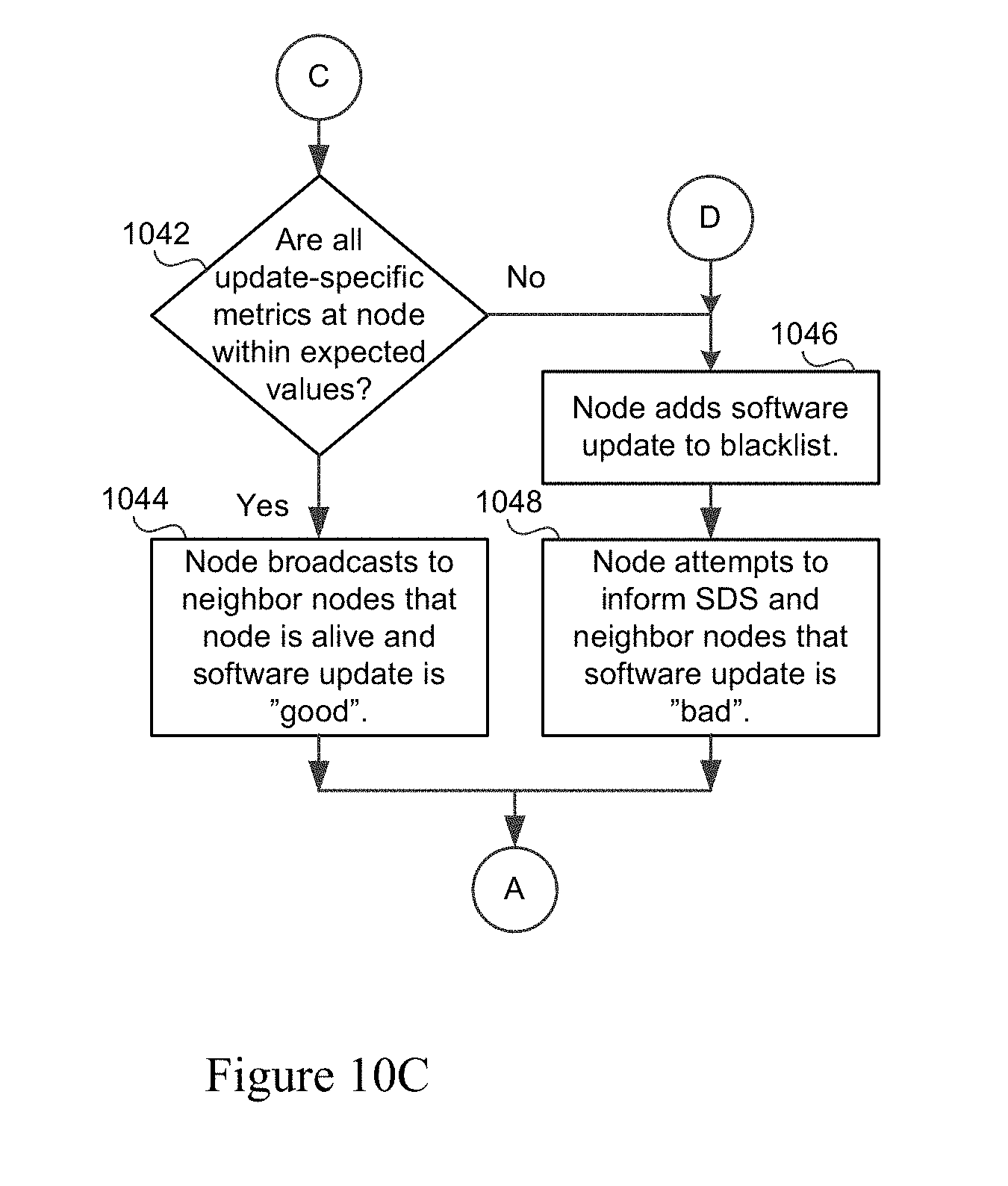
XML
uspto.report is an independent third-party trademark research tool that is not affiliated, endorsed, or sponsored by the United States Patent and Trademark Office (USPTO) or any other governmental organization. The information provided by uspto.report is based on publicly available data at the time of writing and is intended for informational purposes only.
While we strive to provide accurate and up-to-date information, we do not guarantee the accuracy, completeness, reliability, or suitability of the information displayed on this site. The use of this site is at your own risk. Any reliance you place on such information is therefore strictly at your own risk.
All official trademark data, including owner information, should be verified by visiting the official USPTO website at www.uspto.gov. This site is not intended to replace professional legal advice and should not be used as a substitute for consulting with a legal professional who is knowledgeable about trademark law.