Articulating wave energy conversion system using a compound lever-arm barge
Murtha, Jr. , et al.
U.S. patent number 10,359,023 [Application Number 15/871,577] was granted by the patent office on 2019-07-23 for articulating wave energy conversion system using a compound lever-arm barge. This patent grant is currently assigned to MURTECH, INC.. The grantee listed for this patent is Murtech, Inc.. Invention is credited to Michael E. McCormick, Robert C. Murtha, Jr..


| United States Patent | 10,359,023 |
| Murtha, Jr. , et al. | July 23, 2019 |
Articulating wave energy conversion system using a compound lever-arm barge
Abstract
An articulating wave energy conversion system (AWECS) formed of a forward barge hingedly-coupled to a two-part aft barge configuration for reducing the attenuation of available wave energy along the length of the AWECS. The two-part aft barge includes a buoyant section that is either rigidly-connected, or unitized with, a lever-arm barge. The lever-arm barge includes a draft that is much smaller than the drafts of the forward barge and buoyant section. In addition, the lever-arm barge includes a large waterplane area that results in large hydrostatic forces as the waves pass. One or more intermediate barges may be hingedly-coupled between the forward barge and the aft barge. Pumps can be positioned across every hinge to convert the barge articulations into mechanical energy for driving the pumps based on wave motion for a variety of functions, such as water desalination, electrical energy generation, etc.
| Inventors: | Murtha, Jr.; Robert C. (Stevensville, MD), McCormick; Michael E. (Annapolis, MD) | ||||||||||
|---|---|---|---|---|---|---|---|---|---|---|---|
| Applicant: |
|
||||||||||
| Assignee: | MURTECH, INC. (Glen Burnie,
MD) |
||||||||||
| Family ID: | 62838827 | ||||||||||
| Appl. No.: | 15/871,577 | ||||||||||
| Filed: | January 15, 2018 |
Prior Publication Data
| Document Identifier | Publication Date | |
|---|---|---|
| US 20180202413 A1 | Jul 19, 2018 | |
Related U.S. Patent Documents
| Application Number | Filing Date | Patent Number | Issue Date | ||
|---|---|---|---|---|---|
| 62447490 | Jan 18, 2017 | ||||
| Current U.S. Class: | 1/1 |
| Current CPC Class: | F03G 7/08 (20130101); F03B 13/20 (20130101); Y02E 10/30 (20130101); Y02E 10/38 (20130101); F05B 2250/411 (20130101); Y02A 20/144 (20180101); F05B 2250/73 (20130101); F05B 2260/406 (20130101) |
| Current International Class: | F03B 13/20 (20060101); F03G 7/08 (20060101) |
| Field of Search: | ;290/42,53 ;60/500 |
References Cited [Referenced By]
U.S. Patent Documents
| 71287 | November 1867 | Dennison et al. |
| 260016 | June 1882 | Franklin |
| 344813 | July 1886 | Bull |
| 882883 | March 1908 | Hillson |
| 917411 | April 1909 | Cassella |
| 1078323 | November 1913 | Trull |
| 1636447 | July 1927 | Standish |
| 2731799 | January 1956 | Lange et al. |
| 3022632 | February 1962 | Parks |
| 3191202 | June 1965 | Handler |
| 3376588 | April 1968 | Berteaux |
| 3628334 | December 1971 | Coleman |
| 3755836 | September 1973 | Milazzo |
| 3818523 | June 1974 | Stillman, Jr. |
| 3846990 | November 1974 | Bowley |
| 3848419 | November 1974 | Bowley |
| 4004308 | January 1977 | Gongwer |
| 4048802 | September 1977 | Bowley |
| 4077213 | March 1978 | Hagen |
| 4098084 | July 1978 | Cockerell |
| 4118932 | October 1978 | Sivill |
| 4209283 | June 1980 | Marbury |
| 4210821 | July 1980 | Cockrell |
| 4255066 | March 1981 | Mehlum |
| 4264233 | April 1981 | McCambridge |
| 4280238 | July 1981 | van Heijst |
| 4326840 | April 1982 | Hicks et al. |
| 4335576 | June 1982 | Hopfe |
| RE31111 | December 1982 | Hagen |
| 4408454 | October 1983 | Hagen |
| 4421461 | December 1983 | Hicks et al. |
| 4512886 | April 1985 | Hicks et al. |
| 4684815 | August 1987 | Gargos |
| 4686377 | August 1987 | Gargos |
| 4698969 | October 1987 | Raichlen et al. |
| 4781023 | November 1988 | Gordon |
| 4894873 | January 1990 | Kiefer et al. |
| 4954110 | September 1990 | Warnan |
| 5112483 | May 1992 | Cluff |
| 5132550 | July 1992 | McCabe |
| 5186822 | February 1993 | Tzong et al. |
| 5359229 | October 1994 | Youngblood |
| 5558459 | September 1996 | Odenbach et al. |
| 5584673 | December 1996 | Rein |
| 5600961 | February 1997 | Whipple, III |
| 5879105 | March 1999 | Bishop et al. |
| 6406221 | June 2002 | Collier |
| 6451204 | September 2002 | Anderson |
| 6476511 | November 2002 | Yemm et al. |
| 6647716 | November 2003 | Boyd |
| 6863806 | March 2005 | Stark et al. |
| 7023104 | April 2006 | Kobashikawa |
| 7042112 | May 2006 | Wood |
| 7245041 | July 2007 | Olson |
| 7264420 | September 2007 | Chang |
| 7443047 | October 2008 | Ottersen |
| 7579704 | August 2009 | Steenstrup et al. |
| 7658843 | February 2010 | Krock et al. |
| 7694513 | April 2010 | Steenstrup et al. |
| 7728453 | June 2010 | Evans |
| 7900571 | March 2011 | Jaber et al. |
| 8193651 | June 2012 | Lightfoot |
| 8304925 | November 2012 | Yang |
| 8358025 | January 2013 | Hogmoe |
| 8564151 | October 2013 | Huenber |
| 8650869 | February 2014 | McCormick |
| 8778176 | July 2014 | Murtha |
| 8784653 | July 2014 | Murtha |
| 8866321 | October 2014 | McCormick |
| 9115689 | August 2015 | Malligere |
| 9334860 | May 2016 | Knowles, Jr. et al. |
| 9435317 | September 2016 | Cunningham et al. |
| 9702334 | July 2017 | Murtha, Jr. |
| 10029927 | July 2018 | Murtha |
| 10030645 | July 2018 | Knowles |
| 2003/0010691 | January 2003 | Broussard |
| 2003/0121408 | July 2003 | Linerode et al. |
| 2006/0112871 | June 2006 | Dyhrberg |
| 2006/0283802 | December 2006 | Gordon |
| 2007/0108112 | May 2007 | Jones et al. |
| 2007/0200353 | August 2007 | Ottersen |
| 2009/0084296 | April 2009 | McCormick |
| 2010/0054961 | March 2010 | Palecek et al. |
| 2010/0320759 | December 2010 | Lightfoot et al. |
| 2011/0089689 | April 2011 | Gregory |
| 2011/0121572 | May 2011 | Levchets et al. |
| 2011/0299927 | December 2011 | McCormick et al. |
| 2011/0304144 | December 2011 | Dehlsen et al. |
| 2012/0025532 | February 2012 | Song |
| 2012/0067820 | March 2012 | Henthorne et al. |
| 2013/0008158 | January 2013 | Hon |
| 2013/0008164 | January 2013 | Cunningham et al. |
| 2014/0008306 | January 2014 | Murtha |
| 2014/0091575 | April 2014 | McCormick |
| 2014/0158624 | June 2014 | Murtha |
| 2016/0236950 | August 2016 | Murtha |
| 2016/0273513 | September 2016 | Murtha, Jr. |
| 2017/0129788 | May 2017 | Murtha, Jr. |
| 2018/0010570 | January 2018 | Murtha, Jr. |
| 1193490 | Sep 1985 | CA | |||
| 201620995 | Nov 2010 | CN | |||
| 2248260 | Apr 1974 | DE | |||
| 2437507 | Apr 1980 | FR | |||
| 2113311 | Aug 1983 | GB | |||
| 2459112 | Oct 2009 | GB | |||
| 2002142498 | May 2002 | JP | |||
| 20110020077 | Mar 2011 | KR | |||
| WO 95/10706 | Apr 1995 | WO | |||
| WO 01/96738 | Dec 2001 | WO | |||
| WO 03/026954 | Apr 2003 | WO | |||
| WO 2013/115581 | Aug 2013 | WO | |||
Other References
|
Bernitsas, et al., "VIVACE (Vortex Induced Vibration for Aquatic Clean Energy): A New Concept in Generation of Clean and Renewable Energy from Fluid Flow," Proceedings of OMAE2006, Paper OMAE06-92645, Hamburg, Germany Jun. 4-9, 2006, pp. 1-18. cited by applicant . Blevins, Robert D., "Flow-Induced Vibrations," Van Nostrand Reinhold, New York, 1990, pp. 194-213. cited by applicant . Budar, et al., "A Resonant Point Absorber of Ocean-Wave Power," Nature, vol. 256, Aug. 1975, pp. 478-480. cited by applicant . Cebron, et al., "Vortex-Induced Vibrations Using Wake Oscillator Model Comparison on 2D Response with Experiments," Institute of Thermomechanics, Prague, 2008. cited by applicant . Falnes, Johannes, "Ocean Waves Oscillating Systems," Cambridge University Press, pp. 196-224, 2002. cited by applicant . Farshidianfar, et al., "The Lock-in Phenomenon in VIV Using a Modified Wake Oscillator Model for Both High and Low Mass-Damping Ratio," Iranian Journal of Mechanical Engineering, vol. 10, No. 2, Sep. 2009. cited by applicant . Garnaud, et al, "Comparison of Wave Power Extraction by a Compact Array of Small Buoys and by a Large Buoy," Proceedings of the 8th European Wave and Tidal Energy Conference, Uppsala, Sweden, 2009, pp. 934-942. cited by applicant . Jauvitis, et al., The Effect of Two Degrees of Freedom on Vortex-Induced Vibration at Low Mass and Damping,: J. Fluid Mechanics, vol. 509, 2004, pp. 23-62. cited by applicant . Lee, et al., "On the Floating Breakwater--A New Arrangement," Proceedings, International Conf. on Coastal Engineering, Taipei, 1986, pp. 2017-2022. cited by applicant . Leong, et al., "Two-Degree-of-Freedom Vortex-Induced Vibration of a Pivoted Cylinder Below Critical Mass Ratio," Proceedings of the Royal Society A, vol. 464, 2008, pp. 2907-2927. cited by applicant . Liang, et al., "A Study of Spar Buoy Floating Breakwater," Ocean Engineering, vol. 31, 2004, pp. 43-60. cited by applicant . McCormick, et al., "Full-Scale Experimental Study of Bi-Modal Buoy," Report EW 01-11, Department of Naval Architecture and Ocean Engineering, U.S. Naval Academy, Jun. 2011, 32 pages. cited by applicant . McCormick, et al., "Planing Characteristics of Fast-Water Buoys," Journal of the Waterways Harbors and Coastal and Engineering Division, vol. 99, No. WW4, Nov. 1973, pp. 485-493. cited by applicant . McCormick, et al., "Prototype Study of a Passive Wave-Energy Attenuating Bi-Modal Buoy," Murtech, Inc. Report M-12-1, Jan. 2012, 26 pages. cited by applicant . Miles, John W., "On the Interference Factors for Finned Bodies," J. Aeronautical Sciences, vol. 19, No. 4, Apr. 1952, p. 287. cited by applicant . Murali, et al., "Performance of Cage Floating Breakwater," Journal of Waterway, Port, Costal and Ocean Engineering, Jul./Aug. 1997, pp. 1-8. cited by applicant . Ng, et al., "An Examination of Wake Oscillator Models for Vortex-Induced Vibrations," Naval Undersea Warfare Center Division, Newport, RI, Technical Report 11,298, Aug. 1, 2011, 18 pages. cited by applicant . Ogink, et al., "A Wake Oscillator With Frequency Dependent Coupling for the Modeling of Vortex-Induced Vibration," Journal of Sound and Vibration, No. 329, 2010, pp. 5452-5473. cited by applicant . Rodenbusch, George, "Response of a Pendulum Spar to 2-Dimensional Random Waves and a Uniform Current," Massachusetts Institute of Technology and Woods Hole Oceanographic Institution, Engineering Program, Ph.D. Dissertation, Aug. 1978, 138 pages. cited by applicant . Ryan, et. al., "Energy Transfer in a Vortex Induced Vibrating Tethered Cylinder System", Conf. on Bluff Body Wakes and Vortex-Induced Vibrations, Port Douglas, Australia, Dec. 2002, 4 pages. cited by applicant . Shiguemoto, et al., "Vortex Induced Motions of Subsurface Buoy with a Vertical Riser: A Comparison Between Two Phenomenological Models" Proceedings, 23.degree. Congresso Nacional de Transporte Aquaviario, Construc o Naval e Offshore, Rio de Janeiro, Oct. 25-29, 2010, pp. 1-9. cited by applicant . Sobey, et al., "Hydrodynamic of Circular Piles," Proceedings, 6th Australian Hydraulics and Fluid Mechanics Conference, Adelaide, Dec. 1977, pp. 253-256. cited by applicant . Long Beach Water Department, Under-Ocean Floor Seawater intake and Discharge Test Plan, Apr. 1, 2009. cited by applicant . Lovo, Robert, "Initial Evaluation of the Subfloor Water Intake Structure System (SWISS) vs. Conventional Multimedia Pretreatment Techniques," Assistance Agreement No. 98-FC-81/0044, Desalination Research and Development Program Report No. 66, U.S. Dept. of Interior, May 2001. cited by applicant . McCormick, "Ocean Wave Energy Conversion," Wiley-Interscience, New York (1981, reprinted by Dover Publication, Long Island, New York in 2007). cited by applicant . WateReuse Association, "Overview of Desalination Plan Intake Alternatives", Mar. 2011. cited by applicant . International Search Report for related PCT Application No. PCT/US2013/059175 dated Mar. 19, 2014. cited by applicant . International Search Report for related PCT Application No. PCT/US2013/048906 dated Sep. 30, 2013. cited by applicant . International Search Report for corresponding PCT Application No. PCT/US2014/056243 dated Dec. 15, 2014. cited by applicant . International Seach Report for corresponding PCT Application No. PCT/US2016/022438 dated Jun. 21, 2016. cited by applicant . International Search Report for related PCT Application No. PCT/US2018/013703 dated Apr. 27, 2018. cited by applicant . English Abstract of WO 2013/115581. cited by applicant. |
Primary Examiner: Cuevas; Pedro J
Attorney, Agent or Firm: Caesar Rivise, PC
Parent Case Text
CROSS-REFERENCE TO RELATED APPLICATIONS
This non-provisional application claims the benefit under 35 U.S.C. .sctn. 119(e) of Application Ser. No. 62/447,490 filed on Jan. 18, 2017 entitled ARTICULATING WAVE ENERGY CONVERSION SYSTEM USING A COMPOUND LEVER-ARM BARGE, and whose entire disclosure is incorporated by reference herein.
Claims
What is claimed is:
1. A system for converting wave energy from a body of water having waves into usable mechanical energy, said system comprising: an articulated barge system for floating on the body of water having waves, said barge system comprising: a first barge that is pivotally-coupled to a second barge having two portions, said first portion having a draft that is similar to a draft of said first barge, said second portion comprising a lever-arm barge having a large waterplane that forms a draft that is smaller than the draft of said first portion when said first and second barges are positioned in the body of water; and at least one pump positioned across said pivot that converts wave energy into pump motion when said first and second barges articulate; and wherein said lever-arm barge reduces attenuation of available wave energy along a length of said second barge.
2. The system of claim 1 further comprising at least one intermediate barge, said at least one intermediate barge being pivotally-coupled to said first barge along a first side of said intermediate barge and being pivotally-coupled to said second barge along a second side, opposite said first side.
3. The system of claim 2 wherein said at least one intermediate barge comprises a draft similar to said draft of said first barge.
4. The system of claim 1 wherein said first portion is rigidly-connected to said lever-arm barge.
5. The system of claim 1 wherein said first portion is unitized with said second portion.
6. The system of claim 1 wherein said pivotal coupling comprises a hinge.
7. The system of claim 2 wherein said pivotal coupling comprises a hinge.
8. A method for converting wave energy from a body of water having waves into usable mechanical energy, said method comprising: forming a first barge having a two portion configuration, said first portion comprising a buoyant element having a first draft when positioned in the body of water and said second portion comprising a lever-arm barge having a large waterplane that forms a second draft when positioned in the body of water, said second draft being less than said first draft; pivotally-coupling said first portion to a second barge and which also comprises said first draft when said second barge is positioned in the body of water; positioning at least one pump across said pivotal coupling for converting wave energy into pump motion; orienting said first and second barges such that said second barge encounters wave motion first; and permitting said first barge and said second barge to articulate when exposed to said wave motion and wherein said lever-arm barge reduces attenuation of available wave energy along a length of said first barge.
9. The method of claim 8 further comprising the step of pivotally-coupling at least one intermediate barge between said first and second barge, said at least one intermediate barge comprising said first draft when positioned on the body of water.
10. The method of claim 9 wherein said step of pivotally-coupling at least one intermediate barge between said first and second barge comprises pivotally coupling said at least one intermediate barge to said first barge along a first side of said at least one intermediate barge and pivotally coupling said at least one intermediate barge to said first portion along a second side of said at least one intermediate barge, said second side being opposite said first side.
11. The method of claim 8 wherein said step of forming a first barge comprises rigidly-connecting said first portion to said lever-arm barge.
12. The method of claim 8 wherein said step of forming a first barge comprises unitizing said first portion with said lever-arm barge.
13. The method of claim 8 wherein said step of pivotally-coupling said first portion to a second barge comprises hingedly-coupling said first portion to said second barge.
14. The method of claim 9 wherein said step of pivotally-coupling at least one intermediate barge between said first and second barge comprises hingedly-coupling said at least one intermediate barge between said first portion and said second barge.
Description
BACKGROUND OF THE INVENTION
The present invention relates in general to wave energy conversion systems and, more particularly, to an articulating wave energy conversion system that minimizes incident wave energy attenuation using a compound lever-arm barge.
Richard Peter McCabe devised the McCabe Wave Pump, which is described in U.S. Pat. No. 5,132,550. The McCabe Wave Pump consists of three rectangular steel pontoons, which move relative to each other in the waves. A damper wave plate attached to the central pontoon ensures that it remains stationary as the fore and aft pontoons move relative to the central pontoon by pitching about the hinges. Energy is extracted from the rotation about the hinge points by linear hydraulic pumps mounted between the central and other two pontoons near the hinges.
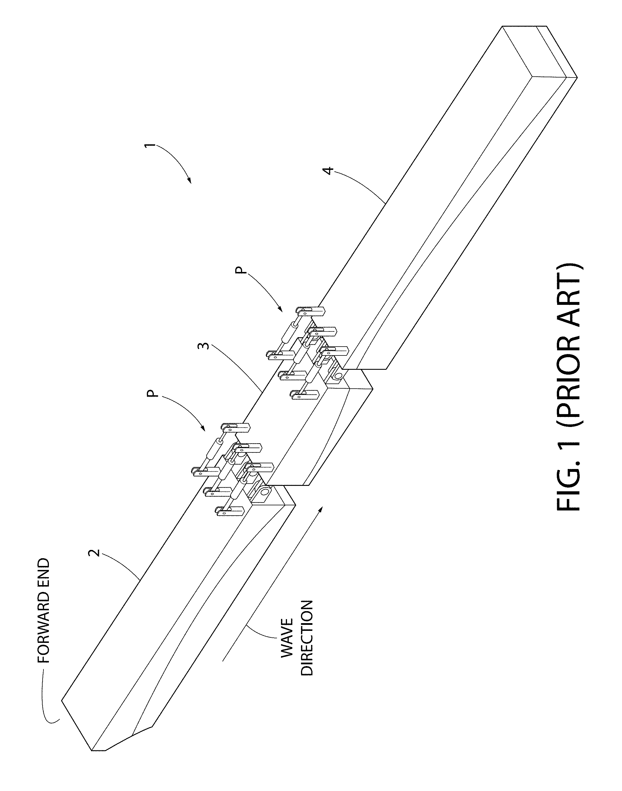
A related configuration to the McCabe Wave Pump is an "articulating wave energy conversion system (AWECS)" which is disclosed in U.S. Pat. No. 8,778,176 (Murtha, et al.); U.S. Pat. No. 8,784,653 (Murtha, et al.); and U.S. Pat. No. 8,866,321 (McCormick, et al.), and all of which are owned by the same Assignee as the present application, namely, Murtech, Inc. of Glen Burnie, Md. See also U.S. Pat. No. 8,650,869 (McCormick). As shown in FIG. 1, an AWECS 1 uses a plurality of pneumatic or hydraulic pumps P (hereinafter, "hydraulic" is used, it being understood that "pneumatic" is also interchangeable with "hydraulic") that straddle the two articulating barges, a forward barge 2 and a rear (also referred to as "aft") barge 4 which are coupled together, e.g. by hinges to a central barge 3. Although not shown, a damper wave plate may be attached to the central barge 3 and submerged in the water which ensures that it remains stationary as the fore 2 and aft 4 barges move relative to the central barge 3 by pitching about the hinges. As an incoming wave makes contact with the forward barge 2 first, the hydraulic fluid in the pumps P coupled between the forward barge 2 and the center barge 3 are driven in a first direction; as the wave continues, the hydraulic fluid in the pumps P coupled between the rear barge 4 and the center barge 3 are driven in a second opposite direction. The end results are bi-directional hydraulic pumps P. The high pressure fluid output of these hydraulic pumps P may be used for a variety of functions such as, but not limited to, water desalination, irrigation of salt water vegetation or various energy conversions.
However, in the wave-energy conversion process, the design orientation of the system with the incident waves is such that the bow line is assumed to be parallel with the incident wave crest. As the waves pass the system, the barges 2/4 are excited, mainly in angular pitching motions. If pumps are connected to the barges, and placed over or under the hinges in FIG. 1, the pumps are excited by the barge motions. This is called the "power takeoff", or PTO, mechanism. As the waves travel along the floating system, the available energy in the neighborhood of the barge is reduced because of the absorption of the forward barge (or barges). The absorbed energy is somewhat replaced by the process called wave diffraction, where wave energy travels along the crest from a high-energy local to a low-energy local--the latter being the neighborhood of the articulated barge.
As can be appreciated from the foregoing, the attenuation of the available wave energy along the length of the articulated-barge system length poses a problem. That is, less energy is available to the after barge or barges.
Thus, there remains a need for an articulated wave energy conversion system that can minimize the attenuation of available wave energy along the length of the articulated-barge system length so that the energy of the incident waves can be converted into significant mechanical energy (e.g., large pump pressures) for use in such things as potable water production, electrical energy generation, etc.
All references cited herein are incorporated herein by reference in their entireties.
BRIEF SUMMARY OF THE INVENTION
A system for converting wave energy from a body of water having waves (e.g., ocean, sea, fresh water, etc.) into usable mechanical energy is disclosed. The system comprises: an articulated barge system for floating on the body of water having waves and wherein the barge system comprises: a first barge that is pivotally-coupled (e.g., a hinge) to a second barge having two portions, wherein the first portion has a draft that is similar to a draft of the first barge, and wherein the second portion comprises a lever barge having a large waterplane that forms a draft that is smaller than the draft of the first portion when the first and second barges are positioned in the body of water; and at least one pump (e.g., a bi-directional pump, etc.) positioned across the pivotal coupling that converts wave energy into pump motion when the first and second barges articulate; and wherein the lever-arm barge reduces attenuation of available wave energy along a length of the second barge.
A method for converting wave energy from a body of water having waves (e.g., ocean, sea, fresh water, etc.) into usable mechanical energy is disclosed. The method comprises: forming a first barge having a two portion configuration, wherein the first portion comprises a buoyant element having a first draft when positioned in the body of water and the second portion comprising a lever arm barge having a large waterplane that forms a second draft when positioned in the body of water, and wherein the second draft is less than the first draft; pivotally-coupling (e.g., a hinge) the first portion to a second barge which also comprises the first draft when the second barge is positioned in the body of water; positioning at least one pump (e.g., a bi-directional pump, etc.) across the pivotal coupling for converting wave energy into pump motion; orienting the first and second barges such that the second barge encounters wave motion first; and permitting the first barge and the second barge to articulate when exposed to the wave motion and wherein the lever-arm barge reduces attenuation of available wave energy along a length of the first barge.
BRIEF DESCRIPTION OF SEVERAL VIEWS OF THE DRAWINGS
Many aspects of the present disclosure can be better understood with reference to the following drawings. The components in the drawings are not necessarily to scale, emphasis instead being placed upon clearly illustrating the principles of the present disclosure. Moreover, in the drawings, like reference numerals designate corresponding parts throughout the several views.
FIG. 1 is an isometric view of a prior art articulating barge wave-energy conversion system (AWECS);
FIG. 2 is a top view of the articulating wave energy conversion system (AWECS) using a compound lever-arm barge of the present invention;
FIG. 2A is a side view of the AWECS using the compound lever-arm barge of the present invention shown in its equilibrium condition;
FIG. 2B is a side of the AWECS of FIG. 2A but showing the difference in drafts of the various barges and the lever-arm barge;
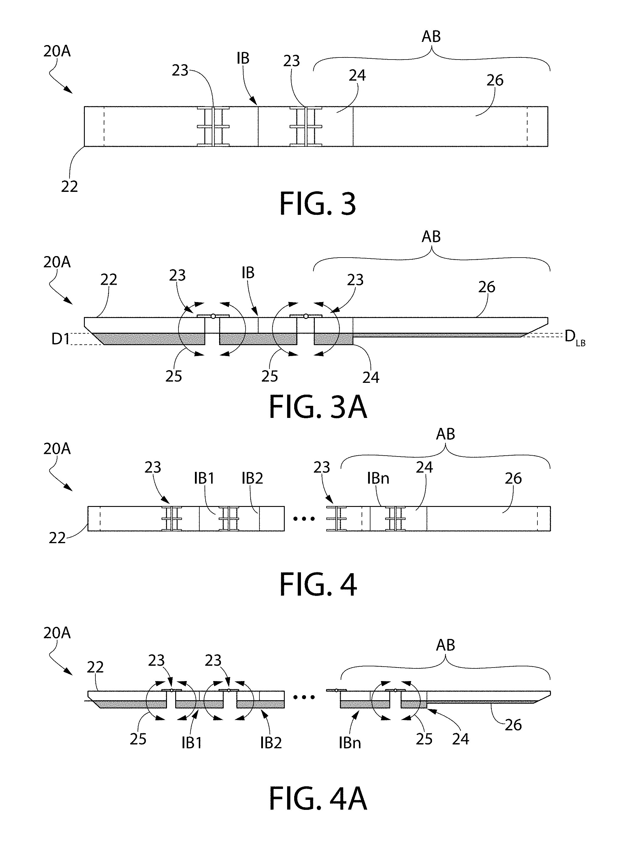
FIG. 3 is a top view of the AWECS using the compound lever-arm barge of the present invention but using an intermediate barge therein;
FIG. 3A is a side view of the AWECS using the compound lever-arm barge of the present invention using an intermediate barge and shown in its equilibrium condition;
FIG. 4 is a top view of the AWECS using the compound lever-arm barge of the present invention but using a plurality of intermediate barges therein;
FIG. 4A is a side view of the AWECS using the compound lever-arm barge of the present invention but using a plurality of intermediate barges therein and shown in its equilibrium condition;
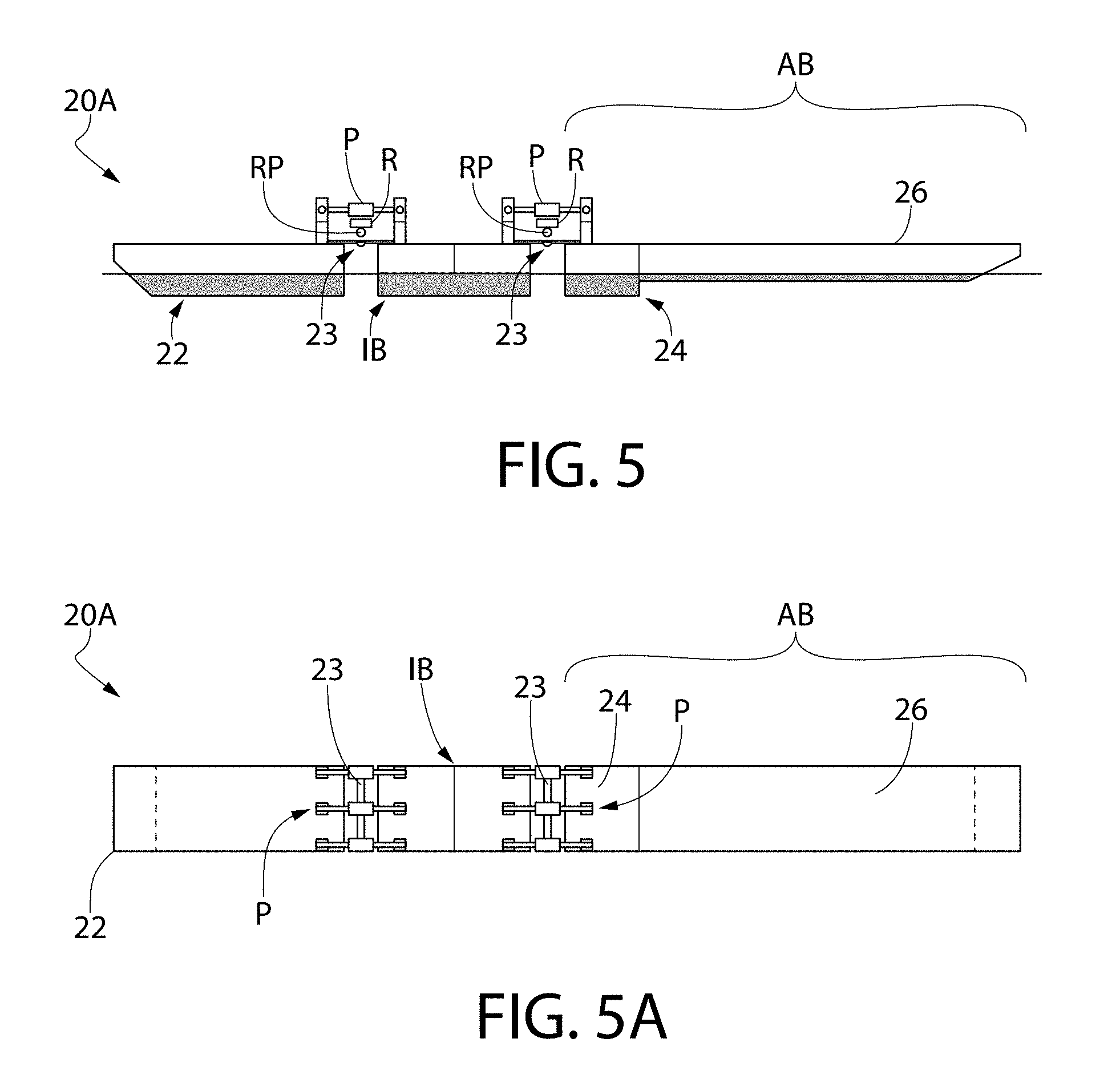
FIG. 5 is a side view of the AWECS using the compound lever-arm barge of the present invention and one intermediate barge and also using including pumps positioned across the hinges, as well as a flow rectifier and a rotary vane pump, by way of example only; and
FIG. 5A is a top view of the AWECS using the compound lever arm and at least one intermediate barge along with a plurality of pumps of FIG. 5.
DETAILED DESCRIPTION OF THE PREFERRED EMBODIMENTS
Referring now to the figures, wherein like reference numerals represent like parts throughout the several views, exemplary embodiments of the present disclosure will be described in detail. Throughout this description, various components may be identified having specific values, these values are provided as exemplary embodiments and should not be limiting of various concepts of the present invention as many comparable sizes and/or values may be implemented.
The present invention 20 comprises a two-part configuration, as shown most clearly in FIGS. 2-2B. In particular, the modified AWECS 20 comprises a front barge 22 that is coupled by a hinge 23 to an aft barge AB that comprises a buoyant portion 24 which is contiguous with a longer thin barge portion, also referred to as a "lever-arm barge" 26. When the modified AWECS 20 is positioned for operation, the incident waves are such that the bow line of the front barge 22 is assumed to be parallel with incident wave crest. The buoyant chamber 24 assists in maintaining the level positions of the decks of the aft barge AB in a still-condition. The buoyant portion 24 may be a separate component that is rigidly-coupled to the lever-arm barge 26; or, the buoyant portion 24 and the lever-arm barge 26 may be a unitized component. Either way, during operation, the lever-arm barge 26 is "down-wave" from the buoyant portion 24.
As the waves pass the modified AWECS 20, the front barge 22 and aft barge AB are excited, mainly in angular motions, as indicated by the arrows 25. If pumps P (FIGS. 5-5A) are connected to the front barge 22 and the after barge AB, (e.g., placed over or under the hinge(s) 23, as shown in FIGS. 5-5A) by way of example only, the pumps P are excited by the barge motions. This is called the "power takeoff", or "PTO mechanism." As can be seen most clearly in FIG. 2B, the lever-arm barge 26 has a smaller draft, D.sub.LB, than the forward barge draft, D1. Furthermore, the lever-arm barge 26 has a large waterplane area (viz., length.times.breadth at the waterline WL). This large waterplane results in large hydrostatic forces as the waves pass. Because of the relatively shallow draft (viz., D.sub.LB), the weight of the barge per unit length is small. For a given wave having a period T and height H, the net wave force on a floating body increases as the draft decreases. This is due to the dynamics of water waves which exponentially increase as the depth decreases; hence, the shallower draft results in a higher net wave force. As a result, the modified AWECS 20 of the present invention is able to convert the energy of incident waves into large pump pressures for use in a variety of processes, e.g., potable water production, pumping, etc.
For example, salt water can be drawn in from the surrounding sea water (or fresh water, if the modified AWECS 20 is positioned in a fresh water environment, etc.) and pre-filtered (associated filters not shown). This pressurized pre-filtered water can then be fed through a flow rectifier R (FIG. 5), if bi-directional pumps P are used, for providing a unidirectional pressurized water flow to an onboard desalination system (not shown) which includes reverse osmosis membranes and from which potatable water is generated. Alternatively, this unidirectional pressurized pre-filtered salt water may be used to irrigate salt water crops. Where electrical energy generation is implemented with the modified AWECS 20, a rotary-vane pump RP may also be included for driving an electrical generator.
It should be understood that FIGS. 2-2B provide the broadest version of the modified AWECS 20. However, as shown in FIGS. 3-3A the modified AWECS 20A may include an intermediate barge D3 between the forward barge 22 and the aft barge AB. In particular, an intermediate barge D3 is shown hingedly coupled to the front barge 22 and to the after barge AB via hinges 23. The intermediate barge D3 has a draft D1 similar to the draft of the forward barge 22. Furthermore, it is within the broadest scope of the present invention whereby a plurality of intermediate barges IB1, IB2, . . . IBn are included in the modified AWECS 20A, as shown in FIGS. 4-4A. The only requirement is that the aft barge AB, comprising the buoyant portion 24 and the lever-arm barge 26, form the last "barge" in the modified AWECS 20A, i.e., being coupled to the last intermediate barge, IBn, as shown in FIGS. 4-4A.
As mentioned previously with respect to the first embodiment 20 of the modified AWECS, pumps, or pump sets, P may be positioned across every hinge 23, whether between the forward barge 22 and the adjacent intermediate barge IB, or between every adjacent intermediate barge IB, or between the forward barge 22 and the aft barge AB, if no intermediate barges D3 are used, etc., as shown in FIGS. 5 and 5A, for generating a pressurized water flow. Flow rectifiers R can also be included to generate a unidirectional pressurized water flow if the pump (or pump sets) P are bi-directional pumps. Rotary vane pumps RP can also be associated with the pumps for generating electrical energy.
Alternatively, the pump or pump sets P may comprise a closed system whereby the pump medium may be hydraulic fluid, rather than water from the surrounding water environment. In that scenario, the barge articulation generates a pressurized hydraulic fluid.
While the invention has been described in detail and with reference to specific examples thereof, it will be apparent to one skilled in the art that various changes and modifications can be made therein without departing from the spirit and scope thereof.
* * * * *
D00000
D00001
D00002
D00003
D00004
XML
uspto.report is an independent third-party trademark research tool that is not affiliated, endorsed, or sponsored by the United States Patent and Trademark Office (USPTO) or any other governmental organization. The information provided by uspto.report is based on publicly available data at the time of writing and is intended for informational purposes only.
While we strive to provide accurate and up-to-date information, we do not guarantee the accuracy, completeness, reliability, or suitability of the information displayed on this site. The use of this site is at your own risk. Any reliance you place on such information is therefore strictly at your own risk.
All official trademark data, including owner information, should be verified by visiting the official USPTO website at www.uspto.gov. This site is not intended to replace professional legal advice and should not be used as a substitute for consulting with a legal professional who is knowledgeable about trademark law.