Intelligent hub cleaning device
Xu , et al. July 23, 2
U.S. patent number 10,357,807 [Application Number 15/797,436] was granted by the patent office on 2019-07-23 for intelligent hub cleaning device. This patent grant is currently assigned to CITIC Dicastal CO., LTD.. The grantee listed for this patent is CITIC Dicastal CO., LTD.. Invention is credited to Minghua Liu, Shiwen Xu, Zhiyuan Yu, Ruixiao Zhou.


| United States Patent | 10,357,807 |
| Xu , et al. | July 23, 2019 |
Intelligent hub cleaning device
Abstract
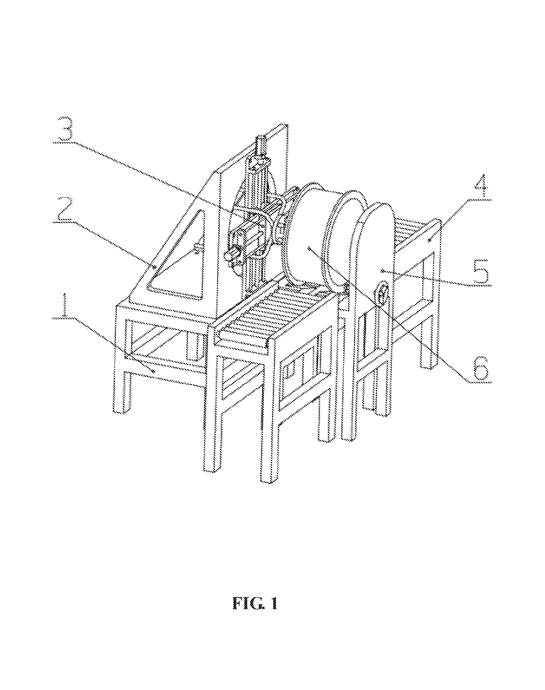
Disclosed is a hub cleaning device, including a base (1), a mounting transition plate (2), a nozzle adjusting module (3), hub conveying modules (4) and a work fixture (5), in which the nozzle adjusting module (3) is connected onto the mounting transition plate (2), and the mounting transition plate (2) is fixed on the base (1); the work fixture (5) is arranged at a position parallel to the base (1), so that the nozzle adjusting module (3) can face the front side of a hub (6); and the hub conveying modules (4) are arranged on two sides of the work fixture (5). The device is simple in structure, and one device can complete cleaning of multiple types of hubs, thereby greatly reducing the input of enterprises on cleaning devices and saving a lot of money for the enterprises.
| Inventors: | Xu; Shiwen (Qinhuangdao, CN), Zhou; Ruixiao (Qinhuangdao, CN), Yu; Zhiyuan (Qinhuangdao, CN), Liu; Minghua (Qinhuangdao, CN) | ||||||||||
|---|---|---|---|---|---|---|---|---|---|---|---|
| Applicant: |
|
||||||||||
| Assignee: | CITIC Dicastal CO., LTD.
(Qinhuangdao, Hebei, CN) |
||||||||||
| Family ID: | 60311681 | ||||||||||
| Appl. No.: | 15/797,436 | ||||||||||
| Filed: | October 30, 2017 |
Prior Publication Data
| Document Identifier | Publication Date | |
|---|---|---|
| US 20190060962 A1 | Feb 28, 2019 | |
Foreign Application Priority Data
| Aug 28, 2017 [CN] | 2017 1 0748186 | |||
| Current U.S. Class: | 1/1 |
| Current CPC Class: | B08B 13/00 (20130101); B05B 15/68 (20180201); B08B 3/02 (20130101); B60B 30/00 (20130101); B08B 3/024 (20130101); B60S 3/042 (20130101); B60B 2310/202 (20130101); B60B 2310/228 (20130101); B05B 13/0627 (20130101); B60B 2360/104 (20130101) |
| Current International Class: | B08B 3/02 (20060101); B08B 13/00 (20060101); B60B 30/00 (20060101) |
| Field of Search: | ;134/113,123,45,57R,172,56R,18,198,58R ;15/53.4,DIG.2,97.3,53.1,53.3,268 |
References Cited [Referenced By]
U.S. Patent Documents
| 2692214 | October 1954 | Hurst |
| 2716772 | September 1955 | Cockrell |
| 2718650 | September 1955 | Haverberg |
| 2761170 | September 1956 | Bonneau |
| 2814825 | December 1957 | Guthrie, Jr. |
| 2822564 | February 1958 | Crivelli |
| 2837759 | June 1958 | Haverberg |
| 2857605 | October 1958 | Weishaar |
| 2910202 | October 1959 | Clarke |
| 2957195 | October 1960 | Almond |
| 3043317 | July 1962 | Hursen |
| 3058133 | October 1962 | Haverberg |
| 3108299 | October 1963 | Baldwin |
| 3191207 | June 1965 | Van Brakel |
| 3305886 | February 1967 | Fricke |
| 3328819 | July 1967 | Doerschlag |
| 3433236 | March 1969 | Long |
| 3446217 | May 1969 | Collier |
| 3448717 | June 1969 | Kuhlman |
| 3517405 | June 1970 | Ebeling |
| 3541627 | November 1970 | Grant |
| 3561031 | February 1971 | Gusse et al. |
| 3628212 | December 1971 | Van Brakel |
| 3643272 | February 1972 | Rickel |
| 3643275 | February 1972 | Van Brakel |
| 3645282 | February 1972 | Kurronen |
| 3729763 | May 1973 | Coley |
| 3822431 | July 1974 | Van Brakel |
| 3844480 | October 1974 | Taylor |
| 3903559 | September 1975 | Kuster |
| 3913162 | October 1975 | Parkin |
| 3915179 | October 1975 | Casson |
| 4023228 | May 1977 | Hanna |
| 4178948 | December 1979 | Swinehart |
| 4269141 | May 1981 | Kennett |
| 4272301 | June 1981 | Galbraith |
| 4424823 | January 1984 | Gougoulas |
| 4550464 | November 1985 | Messing |
| 4651925 | March 1987 | Harris |
| 4718439 | January 1988 | Gorra |
| 4719932 | January 1988 | Burton |
| 4726388 | February 1988 | Swinehart |
| 4805648 | February 1989 | Hour |
| 4830033 | May 1989 | Hanna |
| 4870921 | October 1989 | Svensson |
| 4878262 | November 1989 | Stufflebeam |
| 4895307 | January 1990 | Swinehart |
| 4920997 | May 1990 | Vetter |
| 4946513 | August 1990 | Del Prato |
| 4971084 | November 1990 | Smith |
| 4979536 | December 1990 | Midkiff |
| 4981523 | January 1991 | Larson |
| 4985957 | January 1991 | Belanger |
| 5016662 | May 1991 | Crotts |
| 5033490 | July 1991 | Wade |
| 5040485 | August 1991 | Bailey |
| 5052629 | October 1991 | Belanger |
| 5065694 | November 1991 | Earnheart, Jr. |
| 5090429 | February 1992 | Barber |
| 5098744 | March 1992 | Enegren |
| 5123136 | June 1992 | Belanger |
| 5125981 | June 1992 | Belanger |
| 5148570 | September 1992 | Crotts |
| 5161557 | November 1992 | Scheiter, Jr. |
| 5226436 | July 1993 | Kirby |
| 5226971 | July 1993 | Fogal |
| 5261433 | November 1993 | Smith |
| 5266123 | November 1993 | Brand |
| 5291696 | March 1994 | Enegren |
| 5291906 | March 1994 | White |
| 5309931 | May 1994 | Meyer, III |
| 5341828 | August 1994 | Ferguson, Sr. |
| 5432974 | July 1995 | Yasutake |
| 5730164 | March 1998 | Midkiff |
| 5778908 | July 1998 | Shelstad |
| 5853127 | December 1998 | Heembrock |
| 5911259 | June 1999 | Baldi |
| 5968271 | October 1999 | Maxwell |
| 5991952 | November 1999 | Bintzler |
| 6082634 | July 2000 | MacNeil |
| 6134735 | October 2000 | Zamensky |
| 6260225 | July 2001 | Bowman |
| 6270586 | August 2001 | Soble |
| 6277207 | August 2001 | Gauthier |
| 6325082 | December 2001 | Schlueter |
| 6358330 | March 2002 | McGraw |
| 6372053 | April 2002 | Belanger |
| 6383295 | May 2002 | Frederick, Jr. |
| 6461685 | October 2002 | Gorra |
| 6668466 | December 2003 | Bieg |
| 6679275 | January 2004 | Heinze |
| 7143464 | December 2006 | Brosi |
| 7234186 | June 2007 | Peters |
| 7243665 | July 2007 | Turner |
| 7582164 | September 2009 | Krause |
| 8379925 | February 2013 | Schilling |
| 8769756 | July 2014 | Wentworth |
| 2002/0002986 | January 2002 | Jones |
| 2002/0117193 | August 2002 | Anderson |
| 2002/0121291 | September 2002 | Daum |
| 2002/0162575 | November 2002 | Fratello |
| 2002/0162576 | November 2002 | Fratello |
| 2004/0020519 | February 2004 | Taylor |
| 2004/0035447 | February 2004 | Schleeter |
| 2004/0064908 | April 2004 | Decker |
| 2004/0065349 | April 2004 | Scheiter, Jr. |
| 2004/0221878 | November 2004 | Johnson |
| 2005/0028846 | February 2005 | Fratello |
| 2005/0102777 | May 2005 | Johansson |
| 2005/0229954 | October 2005 | Rosselott |
| 2007/0009656 | January 2007 | Nagase |
| 2007/0068554 | March 2007 | Essenburg |
| 2007/0227558 | October 2007 | Chase |
| 2007/0246088 | October 2007 | Rennie |
| 2007/0289616 | December 2007 | McCadden |
| 2008/0000508 | January 2008 | Lee |
| 2008/0029135 | February 2008 | McCadden |
| 2008/0178402 | July 2008 | Martines |
| 2008/0185019 | August 2008 | Hodge |
| 2009/0025159 | January 2009 | Rau |
| 2009/0217955 | September 2009 | Harrell |
| 2009/0272409 | November 2009 | Petit |
| 2010/0281638 | November 2010 | Reed |
| 2010/0307531 | December 2010 | Aharonov |
| 2011/0035889 | February 2011 | Keusch |
| 2011/0115650 | May 2011 | Wimmer |
| 2013/0186432 | July 2013 | Wimmer |
| 2013/0291906 | November 2013 | Belanger |
| 2013/0333127 | December 2013 | Langer |
| 2014/0170324 | June 2014 | Kohonen |
| 2015/0151314 | June 2015 | Hendricks, Sr. |
Assistant Examiner: Bucci; Thomas
Attorney, Agent or Firm: Cooper Legal Group, LLC
Claims
The invention claimed is:
1. A hub cleaning device, including a base, a mounting transition plate, a nozzle adjusting module, hub conveying modules and a work fixture, wherein the nozzle adjusting module is connected onto the mounting transition plate, and the mounting transition plate is fixed on the base; the work fixture is arranged at such a position that the nozzle adjusting module can face a front side of a hub; one or more of the hub conveying modules are arranged on either sides of the work fixture; the nozzle adjusting module includes a transverse drive motor, a transverse ball screw, a transverse substrate, transverse guide posts, a transverse slide block, water pipes, a longitudinal drive motor, a longitudinal substrate, a longitudinal ball screw, longitudinal guide posts, a longitudinal slide block, a nozzle mounting disc, an ultrasonic sensor and high pressure nozzles; the longitudinal substrate is fixed on the mounting transition plate, the longitudinal drive motor is fixed on the longitudinal substrate, the longitudinal ball screw is mounted on the longitudinal substrate, and a shaft of the longitudinal ball screw is connected with a shaft of the longitudinal drive motor; the longitudinal slide block is mounted on a nut of the longitudinal ball screw and moves together with the nut of the longitudinal ball screw; the longitudinal guide posts penetrate through the longitudinal slide block, and are fixed on the longitudinal substrate to provide linear guiding for the longitudinal slide block; the transverse substrate is connected onto the longitudinal slide block; the transverse drive motor is fixed on the transverse substrate, the transverse ball screw is mounted on the transverse substrate, and a shaft of the transverse ball screw is connected with a shaft of the transverse drive motor; the transverse slide block is mounted on a nut of the transverse ball screw and moves together with the nut of the transverse ball screw; the nozzle mounting disc is fixed on the transverse slide block, and the high pressure nozzles and the ultrasonic sensor are fixed on the nozzle mounting disc; each of the water pipes communicate with each of the high pressure nozzles respectively, and provide high pressure water for the high pressure nozzles; the work fixture includes a support frame, V-shaped blocks, a baffle, a pressure block, a threaded rod, a water fender and a handle; the V-shaped blocks are arranged on the support frame and in two columns and used for center positioning on rims of two sides of the hub, and in each of the two columns there is provided one V-shaped block of the V-shaped blocks, the baffle is arranged on one side of the V-shaped blocks, and the pressure block is arranged on the other side of the V-shaped blocks and used for fixing the hub; the pressure block is adjusted via the handle, and the threaded rod is fixed with the pressure block and the handle and connected with a threaded hole in the support frame.
Description
CROSS-REFERENCE TO RELATED APPLICATIONS
This application is filed based upon and claims priority to Chinese Patent Application No. 201710748186.2, filed on Aug. 28, 2017, the entire contents of which are incorporated herein by reference.
BACKGROUND
The aluminum alloy hub is an important part on an automobile chassis, the manufacturing process is complex, and the production, manufacturing, detection and cleaning links need to be controlled strictly. The cleaning procedure between machining and spraying directly affects the final machining quality of the hub. The exiting hub cleaning methods roughly can be divided into manual, brush and high pressure nozzle ones. The manual cleaning method is low in degree of automation, low in efficiency and severe in working environment, and is thus not suitable for large batch production. In the process of cleaning a hub by a brush cleaning machine, the cleaning of the hub is not simple plane cleaning, the central height of the hub of each vehicle type is different, and the placing angles and positions when automobiles are cleaned are slightly different, so cleaning dead angles and difficult cleaning always exist in the conventional cleaning process. The brush cleaning method cannot realize automatic centering and then cannot effectively clean a hub, and it cannot adapt to cleaning hubs of more vehicle types, so that the vehicle cleaning cost is increased. Although the high pressure nozzle method can be used for cleaning hubs in various shapes, the cleaning area of a single nozzle is small, and a plurality of nozzles are needed to improve the cleaning efficiency, so the cost is increased. Therefore, a device which can adapt to cleaning of different types of hubs and is relatively low in cost in the disclosure has very positive practical significance.
SUMMARY
The disclosure relates to the technical fields of aluminum alloy casting and machining, and specifically relates to a hub cleaning device.
The disclosure is aimed at providing a hub cleaning device, thus overcoming the defects that the traditional hub cleaning methods cannot realize cleaning of multiple types of hubs, have cleaning dead angles, are relatively high in cost and the like.
Hub cleaning device includes a base, a mounting transition plate, a nozzle adjusting module, hub conveying modules and a work fixture.
The nozzle adjusting module is connected onto the mounting transition plate by bolt connection, and the mounting transition plate is fixed on the base by bolt connection. The work fixture is arranged at a position parallel to the base, so that the nozzle adjusting module can face the front side of a hub. The hub conveying modules are arranged on two sides of the work fixture.
The nozzle adjusting module includes a transverse drive motor, a transverse ball screw, a transverse substrate, transverse guide posts, a transverse slide block, water pipes, a longitudinal drive motor, a longitudinal substrate, a longitudinal ball screw, longitudinal guide posts, a longitudinal slide block, a nozzle mounting disc, an ultrasonic sensor and high pressure nozzles. The nozzle adjusting module is characterized in that the longitudinal substrate is fixed on the mounting transition plate by bolt connection, the longitudinal drive motor is fixed on the longitudinal substrate, the longitudinal ball screw is mounted on the longitudinal substrate, and the shaft of the longitudinal ball screw is connected with the shaft of the longitudinal drive motor. The longitudinal slide block is mounted on the nut of the longitudinal ball screw and moves together with the nut. The longitudinal guide posts penetrate through the longitudinal slide block, and are fixed on the longitudinal substrate to provide linear guiding for the longitudinal slide block. The transverse substrate is connected onto the longitudinal slide block by bolt connection. The transverse drive motor is fixed on the transverse substrate, the transverse ball screw is mounted on the transverse substrate, and the shaft of the transverse ball screw is connected with the shaft of the transverse drive motor. The transverse slide block is mounted on the nut of the transverse ball screw and moves together with the nut. The nozzle mounting disc is fixed on the transverse slide block by bolt connection, and the high pressure nozzles and the ultrasonic sensor are fixed on the nozzle mounting disc. The water pipes communicate with the high pressure nozzles, and provide high pressure water for the high pressure nozzles.
The work fixture includes a support frame, V-shaped blocks, a baffle, a pressure block, a threaded rod, a water fender and a handle. The work fixture is characterized in that the V-shaped blocks are arranged on the support frame and in two columns and used for center positioning on rims of two sides of the hub, the baffle is arranged on one side of the V-shaped blocks, and the pressure block is arranged on the other side of the V-shaped blocks and used for fixing the hub. The pressure block is adjusted via the handle, the threaded rod is fixed with the pressure block and the handle and connected with a threaded hole in the support frame by threaded connection, and thus, the pressure block can be adjusted by rotating the handle to clamp hubs of different types.
When the hub of a different type is conveyed to the work fixture by the hub conveying modules, the hub is positioned by the V-shaped blocks, and then the pressure block clamps the hub by tightening the handle. At the moment, the positions of the high pressure nozzles can be adjusted in real time via the nozzle adjusting module, so that they can adapt to different types of hubs. The ultrasonic sensor arranged on the nozzle mounting disc can feed back the distance between the high pressure nozzles and the opposite object in real time. When the distance value is within a given range, the front sides of the high pressure nozzles face the surface of the hub, and the surface needs to be cleaned. When the distance value is beyond the given range, the front sides of the high pressure nozzles do not face the surface of the hub, cleaning is not needed, and then the transverse drive motor or the longitudinal drive motor is controlled to control the high pressure nozzles to move transversely or longitudinally till facing the surface of the hub. Thus, a closed loop control is formed, and the surface that needs to be cleaned can be automatically sought. In addition, the maximum travel of the nozzle adjusting device in each moving direction is set according to the maximum size of different types of hubs to be cleaned, and thus, one hub cleaning device can realize the function of cleaning different types of hubs.
The disclosure is simple in structure and convenient to operate, and one device can complete cleaning of multiple types of hubs, thereby greatly reducing the input of enterprises on cleaning devices and saving a lot of money for the enterprises. In addition, the disclosure is high in degree of intelligence, and can automatically seek the hub surface that needs to be cleaned, thereby avoiding time and cleaner waste on the surface that does not need to be cleaned, further improving the production efficiency and reducing the cost.
BRIEF DESCRIPTION OF THE DRAWINGS
The implementation scheme of the disclosure will be described in detail below in combination with the accompanying drawings.
FIG. 1 is a structural schematic diagram of a hub cleaning device.
FIG. 2 is a structural schematic diagram of a nozzle adjusting device of the disclosure.
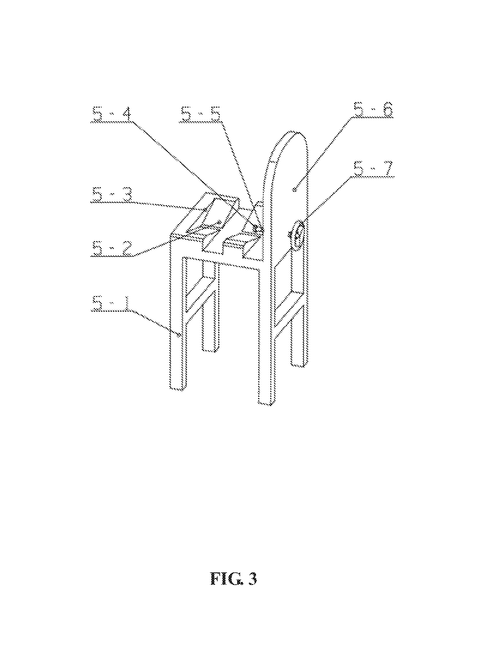
FIG. 3 is a structural schematic diagram of a work fixture of the disclosure.
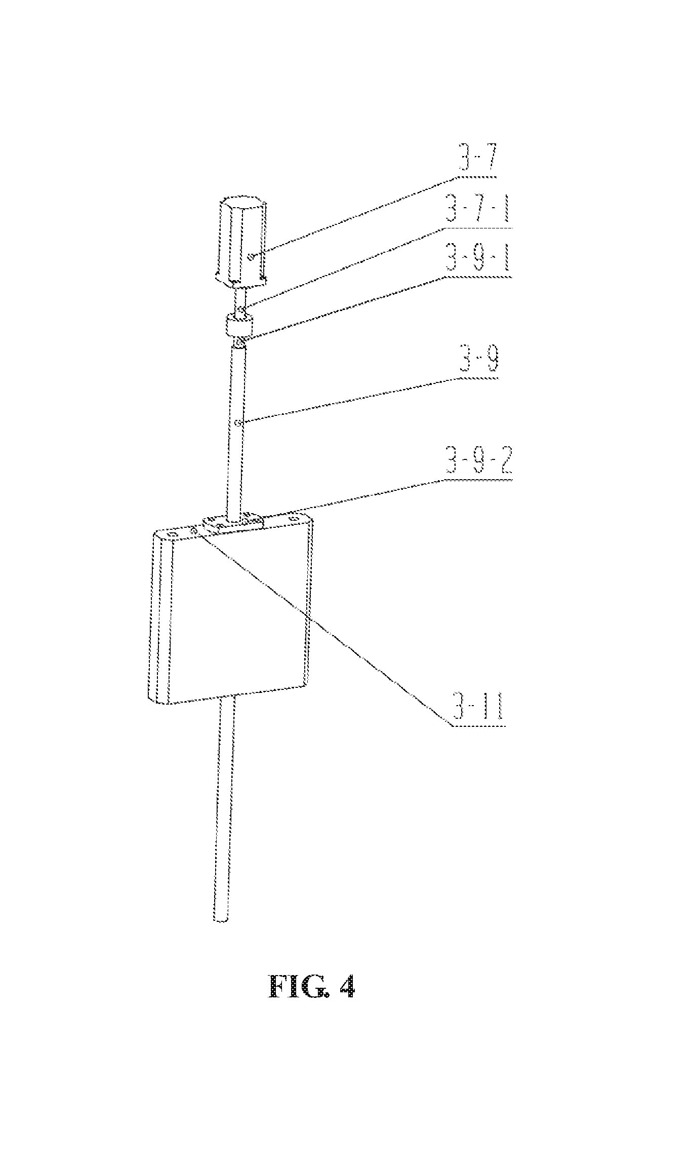
FIG. 4 is a partial schematic diagram of the longitudinal drive motor and the longitudinal ball screw.
FIG. 5 is a partial schematic diagram of the transverse drive motor and the transverse ball screw.
In which, 1--base, 2--mounting transition plate, 3--nozzle adjusting module, 4--hub conveying module, 5--work fixture, 6--hub, 3-1--transverse drive motor, 3-1-1--shaft of the transverse drive motor, 3-2--transverse ball screw, 3-2-1--shaft of the transverse ball screw, 3-2-2--nut of the transverse ball screw, 3-3--transverse substrate, 3-4--transverse guide post, 3-5--transverse slide block, 3-6--water pipe, 3-7--longitudinal drive motor, 3-7-1--shaft of the longitudinal drive motor, 3-8--longitudinal substrate, 3-9--longitudinal ball screw, 3-9-1--shaft of the longitudinal ball screw, 3-9-2--nut of the longitudinal ball screw, 3-10--longitudinal guide post, 3-11--longitudinal slide block, 3-12--nozzle mounting disc, 3-13--ultrasonic sensor, 3-14--high pressure nozzle, 5-1--support frame, 5-2--V-shaped block, 5-3--baffle, 5-4--pressure block, 5-5--threaded rod, 5-6--water fender, 5-7--handle.
DETAILED DESCRIPTION
Embodiment 1
This embodiment discloses a hub cleaning device. The device includes a base 1, a mounting transition plate 2, a nozzle adjusting module 3, hub conveying modules 4 and a work fixture 5.
The nozzle adjusting module 3 is connected onto the mounting transition plate 2 by bolt connection, and the mounting transition plate 2 is fixed on the base 1 by bolt connection. The work fixture 5 is arranged at a position parallel to the base 1, so that the nozzle adjusting module 3 can face the front side of a hub 6. The hub conveying modules 4 are arranged on two sides of the work fixture 5.
The nozzle adjusting module 3 includes a transverse drive motor 3-1, a transverse ball screw 3-2, a transverse substrate 3-3, transverse guide posts 3-4, a transverse slide block 3-5, water pipes 3-6, a longitudinal drive motor 3-7, a longitudinal substrate 3-8, a longitudinal ball screw 3-9, longitudinal guide posts 3-10, a longitudinal slide block 3-11, a nozzle mounting disc 3-12, an ultrasonic sensor 3-13 and high pressure nozzles 3-14. The nozzle adjusting module 3 is characterized in that the longitudinal substrate 3-8 is fixed on the mounting transition plate 2 by bolt connection, the longitudinal drive motor 3-7 is fixed on the longitudinal substrate 3-8, the longitudinal ball screw 3-9 is mounted on the longitudinal substrate 3-8, and the shaft 3-9-1 of the longitudinal ball screw 3-9 is connected with the shaft 3-7-1 of the longitudinal drive motor 3-7. The longitudinal slide block 3-11 is mounted on the nut 3-9-2 of the longitudinal ball screw 3-9 and moves together with the nut. The longitudinal guide posts 3-10 penetrate through the longitudinal slide block 3-11, and are fixed on the longitudinal substrate 3-8 to provide linear guiding for the longitudinal slide block 3-11. The transverse substrate 3-3 is connected onto the longitudinal slide block 3-11 by bolt connection. The transverse drive motor 3-1 is fixed on the transverse substrate 3-3, the transverse ball screw 3-2 is mounted on the transverse substrate 3-3, and the shaft 3-2-1 of the transverse ball screw 3-2 is connected with the shaft 3-1-1 of the transverse drive motor 3-1. The transverse slide block 3-5 is mounted on the nut 3-2-2 of the transverse ball screw 3-2 and moves together with the nut. The nozzle mounting disc 3-12 is fixed on the transverse slide block 3-5 by bolt connection, and the high pressure nozzles 3-14 and the ultrasonic sensor 3-13 are fixed on the nozzle mounting disc 3-12. The water pipes 3-6 communicate with the high pressure nozzles 3-14, and provide high pressure water for the high pressure nozzles 3-14.
The work fixture 5 includes a support frame 5-1, V-shaped blocks 5-2, a baffle 5-3, a pressure block 5-4, a threaded rod 5-5, a water fender 5-6 and a handle 5-7. The work fixture 5 is characterized in that the V-shaped blocks 5-2 are arranged on the support frame 5-1 and in two columns and used for center positioning on rims of two sides of the hub 6, the baffle 5-3 is arranged on one side of the V-shaped blocks 5-2, and the pressure block 5-4 is arranged on the other side of the V-shaped blocks 5-2 and used for fixing the hub 6. The pressure block 5-4 is adjusted via the handle 5-7, the threaded rod 5-5 is fixed with the pressure block 5-4 and the handle 5-7 and connected with a threaded hole in the support frame 5-1 by threaded connection, and thus, the pressure block 5-4 can be adjusted by rotating the handle 5-7 to clamp hubs 6 of different types.
When the hub 6 of a different type is conveyed to the work fixture 5 by the hub conveying modules 4, the hub 6 is positioned by the V-shaped blocks 5-2, and then the pressure block 5-4 clamps the hub 6 by tightening the handle 5-7. At the moment, the positions of the high pressure nozzles 3-14 can be adjusted in real time via the nozzle adjusting module 3, so that they can adapt to different types of hubs 6. The ultrasonic sensor 3-13 arranged on the nozzle mounting disc 3-12 can feed back the distance between the high pressure nozzles 3-14 and the opposite object in real time. When the distance value is within a given range, the front sides of the high pressure nozzles 3-14 face the surface of the hub 6, and the surface needs to be cleaned. When the distance value is beyond the given range, the front sides of the high pressure nozzles 3-14 do not face the surface of the hub 6, cleaning is not needed, and then the transverse drive motor 3-1 or the longitudinal drive motor 3-7 is controlled to control the high pressure nozzles 3-14 to move transversely or longitudinally till facing the surface of the hub 6. Thus, a closed-loop control is formed, and the surface that needs to be cleaned can be automatically sought. In addition, the maximum travel of the nozzle adjusting device 3 in each moving direction is set according to the maximum size of different types of hubs 6 to be cleaned, and thus, one hub cleaning device can realize the function of cleaning different types of hubs 6.
Described above is merely a preferred embodiment of the disclosure. Changes may be made to the specific embodiment and the application scope for those of ordinary skill in the art according to the thought of the disclosure. The content of the specification should not be understood as limiting the disclosure.
* * * * *
D00000
D00001
D00002
D00003
D00004
D00005
XML
uspto.report is an independent third-party trademark research tool that is not affiliated, endorsed, or sponsored by the United States Patent and Trademark Office (USPTO) or any other governmental organization. The information provided by uspto.report is based on publicly available data at the time of writing and is intended for informational purposes only.
While we strive to provide accurate and up-to-date information, we do not guarantee the accuracy, completeness, reliability, or suitability of the information displayed on this site. The use of this site is at your own risk. Any reliance you place on such information is therefore strictly at your own risk.
All official trademark data, including owner information, should be verified by visiting the official USPTO website at www.uspto.gov. This site is not intended to replace professional legal advice and should not be used as a substitute for consulting with a legal professional who is knowledgeable about trademark law.