Accommodating intraocular lenses and methods of use
Smiley , et al. July 23, 2
U.S. patent number 10,357,356 [Application Number 15/064,497] was granted by the patent office on 2019-07-23 for accommodating intraocular lenses and methods of use. This patent grant is currently assigned to PowerVision, Inc.. The grantee listed for this patent is POWERVISION, INC.. Invention is credited to Bryan Patrick Flaherty, Daniel Hildebrand, Terah Whiting Smiley.


| United States Patent | 10,357,356 |
| Smiley , et al. | July 23, 2019 |
Accommodating intraocular lenses and methods of use
Abstract
Accommodating intraocular lenses and methods of use. The accommodating intraocular lenses include peripheral regions that are adapted to be more responsive to certain types of forces than to other types of forces. For example, the accommodating intraocular lenses can include haptics that are stiffer in an anterior-to-posterior direction than in a radial direction.
| Inventors: | Smiley; Terah Whiting (San Francisco, CA), Hildebrand; Daniel (San Francisco, CA), Flaherty; Bryan Patrick (Half Moon Bay, CA) | ||||||||||
|---|---|---|---|---|---|---|---|---|---|---|---|
| Applicant: |
|
||||||||||
| Assignee: | PowerVision, Inc. (Belmont,
CA) |
||||||||||
| Family ID: | 48427677 | ||||||||||
| Appl. No.: | 15/064,497 | ||||||||||
| Filed: | March 8, 2016 |
Prior Publication Data
| Document Identifier | Publication Date | |
|---|---|---|
| US 20160184092 A1 | Jun 30, 2016 | |
Related U.S. Patent Documents
| Application Number | Filing Date | Patent Number | Issue Date | ||
|---|---|---|---|---|---|
| 13672608 | Nov 8, 2012 | ||||
| 12685531 | Jan 11, 2010 | ||||
| 61143559 | Jan 9, 2009 | ||||
| 61557237 | Nov 8, 2011 | ||||
| Current U.S. Class: | 1/1 |
| Current CPC Class: | A61F 2/1624 (20130101); A61F 2/1635 (20130101); A61F 2/1613 (20130101); A61F 2/1648 (20130101); A61F 2/1616 (20130101); A61F 2002/1682 (20150401); A61F 2002/1683 (20130101); A61F 2210/0061 (20130101); A61F 2250/0018 (20130101); A61F 2002/169 (20150401); A61F 2210/0066 (20130101) |
| Current International Class: | A61F 2/16 (20060101) |
| Field of Search: | ;623/6.13,6.15,6.2,6.28,6.27,6.37,6.38,6.49 |
References Cited [Referenced By]
U.S. Patent Documents
| 4111995 | September 1978 | Nelson |
| 4251887 | February 1981 | Anis |
| 4253199 | March 1981 | Banko |
| 4254509 | March 1981 | Tennant |
| 4304895 | December 1981 | Loshaek |
| 4373218 | February 1983 | Schachar |
| 4409691 | October 1983 | Levy |
| 4423809 | January 1984 | Mazzocco |
| 4435855 | March 1984 | Pannu |
| 4435856 | March 1984 | L'Esperance |
| 4466705 | August 1984 | Michelson |
| 4490860 | January 1985 | Rainin |
| 4494254 | January 1985 | Lopez |
| 4512040 | April 1985 | McClure |
| 4528311 | July 1985 | Beard et al. |
| 4575373 | March 1986 | Johnson |
| 4585457 | April 1986 | Kalb |
| 4604295 | August 1986 | Humphreys |
| 4615701 | October 1986 | Woods |
| 4620954 | November 1986 | Singer et al. |
| 4685921 | August 1987 | Peyman |
| 4685922 | August 1987 | Peyman |
| 4693717 | September 1987 | Michelson |
| 4720286 | January 1988 | Bailey et al. |
| 4731078 | March 1988 | Stoy et al. |
| 4731079 | March 1988 | Stoy |
| 4731080 | March 1988 | Galin |
| 4764423 | August 1988 | Yamaguchi et al. |
| 4784485 | November 1988 | Ho |
| 4787903 | November 1988 | Grendahl |
| 4790847 | December 1988 | Woods |
| 4813956 | March 1989 | Gupta |
| 4816031 | March 1989 | Pfoff |
| 4836201 | June 1989 | Patton et al. |
| 4842601 | June 1989 | Smith |
| 4848343 | July 1989 | Wallsten et al. |
| 4888012 | December 1989 | Horn et al. |
| 4892543 | January 1990 | Turely |
| 4902293 | February 1990 | Feaster |
| 4913536 | April 1990 | Barnea |
| 4919151 | April 1990 | Grubbs et al. |
| 4932966 | June 1990 | Christie et al. |
| 4946469 | August 1990 | Sarfarazi |
| 4950289 | August 1990 | Krasner |
| 4963148 | October 1990 | Sulc et al. |
| 4994082 | February 1991 | Richards et al. |
| 4995879 | February 1991 | Dougherty |
| 4995880 | February 1991 | Galib |
| 5015254 | May 1991 | Greite |
| 5035710 | July 1991 | Nakada et al. |
| 5047051 | September 1991 | Cumming |
| 5061914 | October 1991 | Busch et al. |
| 5066301 | November 1991 | Wiley |
| 5078740 | January 1992 | Walman |
| 5145884 | September 1992 | Yamamoto et al. |
| 5145935 | September 1992 | Hayashi |
| 5152789 | October 1992 | Willis |
| 5169920 | December 1992 | Okawa |
| 5171266 | December 1992 | Wiley et al. |
| 5200430 | April 1993 | Federman |
| 5201763 | April 1993 | Brady et al. |
| 5203788 | April 1993 | Wiley |
| 5213579 | May 1993 | Yamada et al. |
| 5224957 | July 1993 | Gasser et al. |
| 5235003 | August 1993 | Ward et al. |
| 5251993 | October 1993 | Sigourney |
| 5275623 | January 1994 | Sarfarazi |
| 5275624 | January 1994 | Nara et al. |
| 5288293 | February 1994 | O'Donnell, Jr. |
| 5290892 | March 1994 | Namdaran et al. |
| 5326347 | July 1994 | Cumming |
| 5391590 | February 1995 | Gerace et al. |
| 5405386 | April 1995 | Rheinish et al. |
| 5426166 | June 1995 | Usifer |
| 5443506 | August 1995 | Garabet |
| 5444106 | August 1995 | Zhou et al. |
| 5444135 | August 1995 | Cheradame et al. |
| 5476514 | December 1995 | Cumming |
| 5489302 | February 1996 | Skottun |
| 5496366 | March 1996 | Cumming |
| 5506300 | April 1996 | Ward et al. |
| 5512609 | April 1996 | Yang |
| 5567365 | October 1996 | Weinschenk, III |
| 5578081 | November 1996 | McDonald |
| 5585049 | December 1996 | Grisoni et al. |
| 5593436 | January 1997 | Langerman |
| 5607472 | March 1997 | Thompson |
| 5628795 | May 1997 | Langerman |
| 5633504 | May 1997 | Collins et al. |
| 5665822 | September 1997 | Bitler et al. |
| 5674282 | October 1997 | Cumming |
| 5676669 | October 1997 | Colvard |
| 5693095 | December 1997 | Freeman et al. |
| 5697973 | December 1997 | Peyman et al. |
| 5702441 | December 1997 | Zhou |
| 5774273 | June 1998 | Bornhorst |
| 5776191 | July 1998 | Mazzocco |
| 5776192 | July 1998 | McDonald |
| 5800533 | September 1998 | Eggleston et al. |
| 5843188 | December 1998 | McDonald |
| 5891931 | April 1999 | Leboeuf et al. |
| 5928282 | July 1999 | Nigam |
| 5964802 | October 1999 | Anello et al. |
| 5968095 | October 1999 | Norrby |
| 5984962 | November 1999 | Anello et al. |
| 6013101 | January 2000 | Israel |
| 6015842 | January 2000 | Leboeuf et al. |
| 6102539 | August 2000 | Tucker |
| 6117171 | September 2000 | Skottun |
| 6124980 | September 2000 | Cerbell |
| 6139576 | October 2000 | Doyle et al. |
| 6160084 | December 2000 | Langer et al. |
| 6176878 | January 2001 | Gwon et al. |
| 6180687 | January 2001 | Hammer et al. |
| 6188526 | February 2001 | Sasaya et al. |
| 6190410 | February 2001 | Lamielle et al. |
| 6195807 | March 2001 | Chou |
| 6197059 | March 2001 | Cumming |
| 6217612 | April 2001 | Woods |
| 6225367 | May 2001 | Chaouk et al. |
| 6229641 | May 2001 | Kosaka |
| 6299641 | October 2001 | Woods |
| 6302911 | October 2001 | Hanna |
| 6322589 | November 2001 | Cumming |
| 6342073 | January 2002 | Cumming et al. |
| 6348437 | February 2002 | Avery et al. |
| 6387126 | May 2002 | Cumming |
| 6388043 | May 2002 | Langer et al. |
| 6406494 | June 2002 | Laguette et al. |
| 6413262 | July 2002 | Saishin et al. |
| 6423094 | July 2002 | Sarfarazi |
| 6436092 | August 2002 | Peyman |
| 6443985 | September 2002 | Woods |
| 6450642 | September 2002 | Jethmalani et al. |
| 6464725 | October 2002 | Skottun |
| 6488708 | December 2002 | Sarfarazi |
| 6493151 | December 2002 | Schachar |
| 6503276 | January 2003 | Lang et al. |
| 6517577 | February 2003 | Callahan et al. |
| 6528602 | March 2003 | Freeman et al. |
| 6551354 | April 2003 | Ghazizadeh et al. |
| 6552860 | April 2003 | Alden |
| 6554859 | April 2003 | Lang et al. |
| 6585768 | July 2003 | Hamano et al. |
| 6589550 | July 2003 | Hodd et al. |
| 6592621 | July 2003 | Domino |
| 6599317 | July 2003 | Weinschenk, III et al. |
| 6601956 | August 2003 | Jean et al. |
| 6610350 | August 2003 | Suzuki et al. |
| 6616691 | September 2003 | Tran |
| 6616692 | September 2003 | Glick et al. |
| 6638304 | October 2003 | Azar |
| 6638305 | October 2003 | Laguette |
| 6638306 | October 2003 | Cumming |
| 6645245 | November 2003 | Preussner |
| 6645246 | November 2003 | Weinschenk, III et al. |
| 6656223 | December 2003 | Brady |
| 6660035 | December 2003 | Lang et al. |
| 6692525 | February 2004 | Brady et al. |
| 6695881 | February 2004 | Peng et al. |
| 6709108 | March 2004 | Levine et al. |
| 6712848 | March 2004 | Wolf et al. |
| 6730123 | May 2004 | Klopotek |
| 6743388 | June 2004 | Sridharan et al. |
| 6749632 | June 2004 | Sandstedt et al. |
| 6749634 | June 2004 | Hanna |
| 6786934 | September 2004 | Zadno-Azizi et al. |
| 6818158 | November 2004 | Pham et al. |
| 6827738 | December 2004 | Willis et al. |
| 6836374 | December 2004 | Esch et al. |
| 6860601 | March 2005 | Shadduck |
| 6878320 | April 2005 | Alderson et al. |
| 6884261 | April 2005 | Zadno-Azizi et al. |
| 6899732 | May 2005 | Zadno-Azizi et al. |
| 6899850 | May 2005 | Haywood et al. |
| 6914247 | July 2005 | Duggan et al. |
| 6926736 | August 2005 | Peng et al. |
| 6935743 | August 2005 | Shadduck |
| 6949093 | September 2005 | Peyman |
| 6966649 | November 2005 | Shadduck |
| 6969403 | November 2005 | Peng et al. |
| 7001374 | February 2006 | Peyman |
| 7041134 | May 2006 | Nguyen et al. |
| 7060094 | June 2006 | Shahinpoor et al. |
| 7068439 | June 2006 | Esch |
| 7070276 | July 2006 | Koretz |
| 7074227 | July 2006 | Portney |
| 7122053 | October 2006 | Esch |
| 7144423 | December 2006 | McDonald |
| 7217288 | May 2007 | Esch et al. |
| 7241312 | July 2007 | Lai et al. |
| 7247168 | July 2007 | Esch et al. |
| 7247689 | July 2007 | Makker et al. |
| 7261737 | August 2007 | Esch et al. |
| 7264351 | September 2007 | Shadduck |
| 7276619 | October 2007 | Kunzler et al. |
| 7278739 | October 2007 | Shadduck |
| 7311194 | December 2007 | Jin et al. |
| 7354451 | April 2008 | Koch |
| 7378382 | May 2008 | Serobian et al. |
| 7416300 | August 2008 | Wei et al. |
| 7438723 | October 2008 | Esch |
| 7452378 | November 2008 | Zadno-Azizi et al. |
| 7453646 | November 2008 | Lo |
| 7485144 | February 2009 | Esch |
| 7494505 | February 2009 | Kappelhof et al. |
| 7637947 | December 2009 | Smith et al. |
| 7675686 | March 2010 | Lo et al. |
| 7753953 | July 2010 | Yee |
| 7759408 | July 2010 | Schorzman et al. |
| 7763069 | July 2010 | Brady et al. |
| 7776088 | August 2010 | Shadduck |
| 7878655 | February 2011 | Salvati et al. |
| 7971997 | July 2011 | Hiramatsu et al. |
| 7988290 | August 2011 | Campbell et al. |
| 7988292 | August 2011 | Neal et al. |
| 7988293 | August 2011 | Raymond et al. |
| 8048155 | November 2011 | Shadduck |
| 8158712 | April 2012 | Your |
| 8162927 | April 2012 | Peyman |
| 8241355 | August 2012 | Brady et al. |
| 8303656 | November 2012 | Shadduck |
| 8314927 | November 2012 | Choi et al. |
| 8328869 | December 2012 | Smiley et al. |
| 8361145 | January 2013 | Scholl et al. |
| 8377125 | February 2013 | Kellan |
| 8425599 | April 2013 | Shadduck |
| 8447086 | May 2013 | Hildebrand et al. |
| 8454688 | June 2013 | Esch et al. |
| 8480734 | July 2013 | Kellan et al. |
| 8613766 | December 2013 | Richardson et al. |
| 8632589 | January 2014 | Helmy |
| 8668734 | March 2014 | Hildebrand et al. |
| 8900298 | December 2014 | Anvar et al. |
| 8956408 | February 2015 | Smiley et al. |
| 8968396 | March 2015 | Matthews et al. |
| 8992609 | March 2015 | Shadduck |
| 9005282 | April 2015 | Chang et al. |
| 9034035 | May 2015 | Betser et al. |
| 9044317 | June 2015 | Hildebrand et al. |
| 9277987 | March 2016 | Smiley et al. |
| 2001/0001836 | May 2001 | Cumming |
| 2001/0016771 | August 2001 | Cumming |
| 2001/0039449 | November 2001 | Johnson et al. |
| 2001/0051826 | December 2001 | Bogaert et al. |
| 2002/0046783 | April 2002 | Johnson et al. |
| 2002/0055777 | May 2002 | Cumming et al. |
| 2002/0072795 | June 2002 | Green |
| 2002/0095212 | July 2002 | Boehm |
| 2002/0107568 | August 2002 | Zadno-Azizi et al. |
| 2002/0111678 | August 2002 | Zadno-Azizi et al. |
| 2002/0116057 | August 2002 | Ting et al. |
| 2002/0116058 | August 2002 | Zadno-Azizi et al. |
| 2002/0116059 | August 2002 | Zadno-Azizi et al. |
| 2002/0116060 | August 2002 | Nguyen et al. |
| 2002/0116061 | August 2002 | Zadno-Azizi et al. |
| 2002/0133228 | September 2002 | Sarver |
| 2002/0161434 | October 2002 | Laguette et al. |
| 2002/0161435 | October 2002 | Portney |
| 2002/0177896 | November 2002 | Israel |
| 2002/0193876 | December 2002 | Lang et al. |
| 2003/0003295 | January 2003 | Dreher et al. |
| 2003/0004569 | January 2003 | Haefliger |
| 2003/0018384 | January 2003 | Valyunin et al. |
| 2003/0042176 | March 2003 | Alderson et al. |
| 2003/0050695 | March 2003 | Lin et al. |
| 2003/0050696 | March 2003 | Cumming |
| 2003/0060878 | March 2003 | Shadduck |
| 2003/0060881 | March 2003 | Glick et al. |
| 2003/0078656 | April 2003 | Nguyen |
| 2003/0078657 | April 2003 | Zadno-Azizi et al. |
| 2003/0078658 | April 2003 | Zadno-Azizi |
| 2003/0083744 | May 2003 | Khoury |
| 2003/0109925 | June 2003 | Ghazizadeh et al. |
| 2003/0109926 | June 2003 | Portney |
| 2003/0130732 | July 2003 | Sarfarazi |
| 2003/0135272 | July 2003 | Brady et al. |
| 2003/0158599 | August 2003 | Brady et al. |
| 2003/0171808 | September 2003 | Phillips |
| 2003/0183960 | October 2003 | Buazza et al. |
| 2003/0187505 | October 2003 | Liao |
| 2003/0199977 | October 2003 | Cumming |
| 2003/0236376 | December 2003 | Kindt-Larsen et al. |
| 2004/0001180 | January 2004 | Epstein |
| 2004/0006386 | January 2004 | Valint et al. |
| 2004/0006387 | January 2004 | Kelman |
| 2004/0008419 | January 2004 | Schachar |
| 2004/0015236 | January 2004 | Sarfarazi |
| 2004/0039446 | February 2004 | McNicholas |
| 2004/0054408 | March 2004 | Glick et al. |
| 2004/0059343 | March 2004 | Shearer et al. |
| 2004/0066489 | April 2004 | Benedikt et al. |
| 2004/0082993 | April 2004 | Woods |
| 2004/0082994 | April 2004 | Woods et al. |
| 2004/0085511 | May 2004 | Uno et al. |
| 2004/0085515 | May 2004 | Roffman et al. |
| 2004/0088050 | May 2004 | Norrby et al. |
| 2004/0111151 | June 2004 | Paul et al. |
| 2004/0111152 | June 2004 | Kelman |
| 2004/0111153 | June 2004 | Woods et al. |
| 2004/0127984 | July 2004 | Paul et al. |
| 2004/0162612 | August 2004 | Portney et al. |
| 2004/0181279 | September 2004 | Nun |
| 2004/0230203 | November 2004 | Yaguchi |
| 2005/0021139 | January 2005 | Shadduck |
| 2005/0090612 | April 2005 | Soane |
| 2005/0113911 | May 2005 | Peyman |
| 2005/0125000 | June 2005 | Tourrette et al. |
| 2005/0131535 | June 2005 | Woods |
| 2005/0165410 | July 2005 | Zadno-Azizi et al. |
| 2005/0251253 | November 2005 | Gross |
| 2005/0264756 | December 2005 | Esch |
| 2006/0069433 | March 2006 | Nun |
| 2006/0100703 | May 2006 | Evans et al. |
| 2006/0116763 | June 2006 | Simpson |
| 2006/0134173 | June 2006 | Liu et al. |
| 2006/0158611 | July 2006 | Piers et al. |
| 2006/0183041 | August 2006 | Erk et al. |
| 2006/0184181 | August 2006 | Cole et al. |
| 2006/0200167 | September 2006 | Peterson et al. |
| 2006/0241752 | October 2006 | Israel |
| 2006/0253196 | November 2006 | Woods |
| 2007/0004886 | January 2007 | Schorzman et al. |
| 2007/0005136 | January 2007 | Richardson |
| 2007/0021831 | January 2007 | Clarke |
| 2007/0027538 | February 2007 | Aharoni et al. |
| 2007/0050023 | March 2007 | Bessiere et al. |
| 2007/0078515 | April 2007 | Brady |
| 2007/0088433 | April 2007 | Esch et al. |
| 2007/0100445 | May 2007 | Shadduck |
| 2007/0118216 | May 2007 | Pynson |
| 2007/0129801 | June 2007 | Cumming |
| 2007/0156236 | July 2007 | Stenger |
| 2007/0162112 | July 2007 | Burriesci et al. |
| 2007/0203578 | August 2007 | Scholl |
| 2007/0213817 | September 2007 | Esch et al. |
| 2007/0244561 | October 2007 | Ben Nun |
| 2007/0260157 | November 2007 | Norrby |
| 2008/0004699 | January 2008 | Ben Nun |
| 2008/0015689 | January 2008 | Esch et al. |
| 2008/0027537 | January 2008 | Gerlach et al. |
| 2008/0033449 | February 2008 | Cole et al. |
| 2008/0035243 | February 2008 | Breitenkamp et al. |
| 2008/0046074 | February 2008 | Smith et al. |
| 2008/0046075 | February 2008 | Esch et al. |
| 2008/0097460 | April 2008 | Boukhny et al. |
| 2008/0139769 | June 2008 | Iwamoto et al. |
| 2008/0179770 | July 2008 | Rooney et al. |
| 2008/0188930 | August 2008 | Mentak et al. |
| 2008/0243247 | October 2008 | Poley et al. |
| 2008/0269887 | October 2008 | Cumming |
| 2008/0300680 | December 2008 | Ben Nun |
| 2008/0306587 | December 2008 | Your |
| 2009/0005865 | January 2009 | Smiley et al. |
| 2009/0076602 | March 2009 | Ho et al. |
| 2009/0124773 | May 2009 | Zhou et al. |
| 2009/0149952 | June 2009 | Shadduck |
| 2009/0228101 | September 2009 | Zadno-Azizi |
| 2009/0234449 | September 2009 | DeJuan, Jr. et al. |
| 2009/0248154 | October 2009 | Dell |
| 2009/0264998 | October 2009 | Mentak et al. |
| 2009/0281620 | November 2009 | Sacharoff et al. |
| 2009/0292293 | November 2009 | Bogaert et al. |
| 2009/0312836 | December 2009 | Pinchuk et al. |
| 2009/0319040 | December 2009 | Khoury |
| 2010/0016963 | January 2010 | Park |
| 2010/0039709 | February 2010 | Lo |
| 2010/0063588 | March 2010 | Park |
| 2010/0069522 | March 2010 | Linhardt et al. |
| 2010/0094412 | April 2010 | Wensrich |
| 2010/0131058 | May 2010 | Shadduck |
| 2010/0131061 | May 2010 | Callahan et al. |
| 2010/0161049 | June 2010 | Inoue |
| 2010/0179653 | July 2010 | Argento et al. |
| 2010/0228344 | September 2010 | Shadduck |
| 2010/0228346 | September 2010 | Esch |
| 2011/0118834 | May 2011 | Lo et al. |
| 2011/0153015 | June 2011 | Simonov et al. |
| 2011/0282442 | November 2011 | Scholl et al. |
| 2011/0288638 | November 2011 | Smiley et al. |
| 2011/0313522 | December 2011 | Hayes |
| 2011/0313523 | December 2011 | Hayes |
| 2012/0078363 | March 2012 | Lu |
| 2012/0078364 | March 2012 | Stenger |
| 2012/0116506 | May 2012 | Compertore |
| 2012/0179249 | July 2012 | Coleman |
| 2012/0221102 | August 2012 | Tanaka et al. |
| 2012/0226351 | September 2012 | Peyman |
| 2012/0245591 | September 2012 | Matthews |
| 2012/0253458 | October 2012 | Geraghty et al. |
| 2012/0253459 | October 2012 | Reich et al. |
| 2012/0303119 | November 2012 | Callahan et al. |
| 2012/0330415 | December 2012 | Callahan et al. |
| 2013/0053954 | February 2013 | Rao et al. |
| 2013/0060331 | March 2013 | Shadduck |
| 2013/0103146 | April 2013 | Smiley et al. |
| 2013/0128368 | May 2013 | Costache et al. |
| 2013/0131794 | May 2013 | Smiley et al. |
| 2013/0184816 | July 2013 | Hayes |
| 2013/0250239 | September 2013 | Hildebrand et al. |
| 2013/0268070 | October 2013 | Esch et al. |
| 2014/0121768 | May 2014 | Simpson |
| 2014/0142587 | May 2014 | Walter et al. |
| 2014/0227437 | August 2014 | DeBoer et al. |
| 2014/0249625 | September 2014 | Shadduck |
| 2015/0087743 | March 2015 | Anvar et al. |
| 2015/0202041 | July 2015 | Shadduck |
| 2015/0238310 | August 2015 | Matthews et al. |
| 2015/0257874 | September 2015 | Hildebrand et al. |
| 2016/0038278 | February 2016 | Matthews |
| 2016/0113761 | April 2016 | Nishi et al. |
| 2017/0049561 | February 2017 | Smiley et al. |
| 2017/0290658 | October 2017 | Hildebrand et al. |
| 2018/0125640 | May 2018 | Smiley et al. |
| 2018/0132997 | May 2018 | Smiley et al. |
| 2018/0147051 | May 2018 | Scholl et al. |
| 2018/0256315 | September 2018 | Hildebrand |
| 2018/0318066 | November 2018 | Campin |
| 1283974 | Feb 2001 | CN | |||
| 1367667 | Sep 2002 | CN | |||
| 1378440 | Nov 2002 | CN | |||
| 1384727 | Dec 2002 | CN | |||
| 101039635 | Sep 2007 | CN | |||
| 101277659 | Oct 2008 | CN | |||
| 102271622 | Dec 2011 | CN | |||
| 202288610 | Jul 2012 | CN | |||
| 0898972 | Mar 1999 | EP | |||
| 2060243 | May 2009 | EP | |||
| 2192934 | May 2011 | EP | |||
| 2784575 | Apr 2000 | FR | |||
| 07-044938 | May 1995 | JP | |||
| 8501715 | Feb 1996 | JP | |||
| 8224295 | Sep 1996 | JP | |||
| 9294754 | Nov 1997 | JP | |||
| 10-206609 | Aug 1998 | JP | |||
| 11-47168 | Feb 1999 | JP | |||
| 11056998 | Mar 1999 | JP | |||
| 11169391 | Jun 1999 | JP | |||
| 11276509 | Oct 1999 | JP | |||
| 11332903 | Dec 1999 | JP | |||
| 2001-502592 | Feb 2001 | JP | |||
| 2003144387 | May 2003 | JP | |||
| 2003-524503 | Aug 2003 | JP | |||
| 2003530978 | Oct 2003 | JP | |||
| 2006341094 | Dec 2006 | JP | |||
| 2007513715 | May 2007 | JP | |||
| 2007518447 | Jul 2007 | JP | |||
| 2008531069 | Aug 2008 | JP | |||
| 2008307394 | Dec 2008 | JP | |||
| 200934451 | Feb 2009 | JP | |||
| 1810052 | Apr 1993 | SU | |||
| WO95/02378 | Jan 1995 | WO | |||
| WO 97/06751 | Feb 1997 | WO | |||
| WO 00/41650 | Jul 2000 | WO | |||
| WO 00/64655 | Nov 2000 | WO | |||
| WO 01/60286 | Aug 2001 | WO | |||
| WO 01/89435 | Nov 2001 | WO | |||
| WO 01/97742 | Dec 2001 | WO | |||
| WO 02/051338 | Jul 2002 | WO | |||
| WO 2004/010895 | Feb 2004 | WO | |||
| WO 2004/046768 | Jun 2004 | WO | |||
| WO 2004/072689 | Aug 2004 | WO | |||
| WO 2005/018504 | Mar 2005 | WO | |||
| WO 2005/084588 | Sep 2005 | WO | |||
| WO 2006/004707 | Jan 2006 | WO | |||
| WO 2006/047383 | May 2006 | WO | |||
| WO 2006/088440 | Aug 2006 | WO | |||
| WO 2007/005529 | Jan 2007 | WO | |||
| WO 2007/005692 | Jan 2007 | WO | |||
| WO 2007/030095 | Mar 2007 | WO | |||
| WO 2007/061688 | May 2007 | WO | |||
| WO 2007/128423 | Nov 2007 | WO | |||
| WO 2007/138564 | Dec 2007 | WO | |||
| WO 2009/100322 | Aug 2009 | WO | |||
| WO 2009/154455 | Dec 2009 | WO | |||
| WO 2011/119334 | Sep 2011 | WO | |||
| WO 2012/006186 | Jan 2012 | WO | |||
Other References
|
Shadduck; U.S. Appl. No. 15/284,350 entitled "Accommodating intraocular lenses," filed Oct. 3, 2016. cited by applicant . Baughman et al., "Negative poisson's ratios for extreme states of matter," Science, vol. 288, pp. 2018-2022, Jun. 16, 2000. cited by applicant . Baughman, "Avoiding the shrink," Nature, vol. 425, pp. 667, Oct. 16, 2003. cited by applicant . Conlisk, A. T. et al; Mass Transfer and Flow in Electrically Charged Micro- and Nano-channels; Analytical Chemistry, vol. 74; iss. 9; pp. 2139-2150; May 2002. cited by applicant . Dubbelman et al.; The Thickness of the Aging Human Lens Obtained from Corrected Scheimpflug Images; Optometry & Vison Science; vo. 78; iss. 6; pp. 411-416; Jun. 2001. cited by applicant . Gorder, P. F.; Electricity can pump medicine in implanted medical devices; Ohio State Research News; 3 pgs.; May 2, 2002 (printed from internet Aug. 19, 2010). cited by applicant . Gordon, "Applications of shape memory polyurethanes," Proceedings of the First Intl Conf. on Shape Memory and Superelastic Tech., Asilomar Conference Center, Pacific Grove, CA, USA, pp. 115-120, Mar. 1994. cited by applicant . Gruber et al.; Exhaustive soxhlet extraction for the complete removal of residual compounds . . . ; Journal of Biomedical Materials Research; vol. 53; No. 5; pp. 445-448; Mar. 2000. cited by applicant . Jeon et al., "Shape memory and nanostructure in poly(norbornyl-POSS) copolymers," Polymer International, vol. 49, pp. 453-457, May 2000. cited by applicant . Kim et al., "Polyurethanes having shape memory effects," Polymer, vol. 37, No. 26, pp. 5781-5793, Dec. 1996. cited by applicant . Lakes et al., "Dramatically stiffer elastic composite materials due to negative stiffness phase?," Journal of the Mechanics and Physics of Solids, vol. 50, pp. 979-1009, May 2002. cited by applicant . Lakes et al., "Extreme damping in composite materials with negative-stiffness inclusions," Nature, vol. 410, pp. 565-567, Mar. 29, 2001. cited by applicant . Lakes et al., "Microbuckling instability in elastomeric cellular sollids," J. Materials Science, vol. 28, pp. 4667-4672, Jan. 1993. cited by applicant . Lakes, "A broader view of membranes," Nature, vol. 414, pp. 503-504, Nov. 29, 2001. cited by applicant . Lakes; Deformations in extreme matter; Science; perspectives; vol. 288; No. 5473; pp. 1976-1977; Jun. 16, 2000. cited by applicant . Lakes, "Extreme damping in compliant composites with a negative-stiffness phase," Philosophical Magazine Letters, vol. 81, No. 2, pp. 95-100, Feb. 2001. cited by applicant . Lakes, "Extreme damping in composite materials with a negative stiffness phase," Physical Review Letters, vol. 86, No. 13, pp. 2897-2900, Mar. 26, 2001. cited by applicant . Lakes, "Negative poisson's ratio materials," Science, vol. 238, pp. 551, Oct. 23, 1987. cited by applicant . Lakes, "No contractile obligations," Nature, vol. 358, pp. 713-714, Dec. 31, 1992. cited by applicant . Langenbucher et al., "Computerized calculation scheme for toric intraocular lenses," Acta Ophthalmologica Scandinavica, vol. 82, No. 3, pp. 270-276, Jun. 2004. cited by applicant . Lendlein et al., "Biodegradable, elastic shape-memory polymers for potential biomedical applications", Science; vol. 296; pp. 1673-1676; May 31, 2002. cited by applicant . Lendlein et al., "Shape-memory polymers," Angew. Chem. Int. Ed.; vol. 41; pp. 2034-2057; Jun. 2002. cited by applicant . Li et al., "Crystallinity and morphology of segmented polyurethanes with different soft-segment length," Journal of Applied Polymer Science, vol. 62, pp. 631-638, Oct. 1996. cited by applicant . Liu et al., "Thermomechanical characterization of a tailored series of shape memory polymers," Journal of Applied Medical Polymers, vol. 6, No. 2, Dec. 2002. cited by applicant . Mather et al., "Strain recovery in POSS hybrid thermoplastics," Polymer Preprints, vol. 41, No. 1, pp. 528-529, Feb. 2000. cited by applicant . Metcalfe et al., "Cold hibernated elastic memory foams for endovascular interventions," Biomaterials, vol. 24, pp. 491-497, Feb. 2003. cited by applicant . Qiao et al.; Bio-inspired accommodating fluidic intraocular lens; Optics Letters; vol. 34; No. 20; pp. 3214-3216; Oct. 15, 2009. cited by applicant . Rosales et al.; Pentacam Scheimpflug QuantitativeImaging of the Crystalline Lens andIntraocular Lens; J. Refractive Surgery; vol. 25; pp. 421-428; May 2009. cited by applicant . Takahashi et al., "Structure and properties of shape-memory polyurethane block copolymers," Journal of Applied Polymer Science, vol. 60, pp. 1061-1069, May 1996. cited by applicant . Tehrani et al.; Capsule measuring ring to predict capsular bag diameter and follow its course after foldable intraocular lens implantation; J Cataract Refract Surg.; vol. 29; No. 11; pp. 2127-2134; Nov. 2003. cited by applicant . Tobushi et al., "Thermomechanical properties of shape memory polymers of polyurethane series and their applications," Journal de Physique IV, Colloque C1, vol. 6, pp. 377-384, Aug. 1996. cited by applicant . Vass et al.; Prediction of pseudophakic capsular bag diameter based on biometric variables; J Cataract Refract Surg.; vol. 25; pp. 1376-1381; Oct. 1999. cited by applicant . Wang et al., "Deformation of extreme viscoelastic metals and composites," Materials Science and Enginerring A, vol. 370, pp. 41-49, Apr. 2004. cited by applicant . Wang et al., "Extreme stiffness systems due to negative stiffness elements," American Journal of Physics, vol. 72, No. 1, pp. 40-50, Jan. 2004. cited by applicant . Wang et al., "Stable extremely-high-damping discrete viscoelastic systems due to native stiffness elements," Applied Physics Letters, vol. 84, No. 22, pp. 4451-4453, May 31, 2004. cited by applicant . Wyant et al; "Basic Wavefront Aberration Theory for Optical Metrology," Applied Optics and Optical Engineering, vol. XI, Aug. 10, 1992: pp. 1, 28-39. cited by applicant . Xu et al., "Making negative poisson's ratio microstructures by soft lithography," Advanced Materials, vol. 11, No. 14, pp. 1186-1189, Jun. 1999. cited by applicant . International Preliminary Report for PCT/US10/020648 dated Jul. 12, 2011; 7 pages. cited by applicant . Smith et al.; U.S. Appl. No. 15/000,783 entitled "Accommodating intraocular lens system having spherical aberration compensation and method," filed Jan. 19, 2016. cited by applicant . Smiley et al.; U.S. Appl. No. 15/064,482 entitled "Accommodating intraocular lenses," filed Mar. 8, 2016. cited by applicant . Matthews et al.; U.S. Appl. No. 15/369,616 entitled "Intraocular lens delivery systems and methods of use," filed Dec. 5, 2016. cited by applicant . Smiley et al.; U.S. Appl. No. 15/457,934 entitled "Lens delivery system," filed Mar. 13, 2017. cited by applicant . Hajela et al.; U.S. Appl. No. 15/575,405 entitled "Intraocular lens materials and components," filed Nov. 20, 2017. cited by applicant. |
Primary Examiner: Prebilic; Paul B
Attorney, Agent or Firm: Levine Bagade Han LLP
Parent Case Text
CROSS-REFERENCE TO RELATED APPLICATIONS
This application is a continuation of U.S. application Ser. No. 13/672,608, filed Nov. 8, 2012, which is a continuation-in-part of U.S. application Ser. No. 12/685,531, filed Jan. 11, 2010, now abandoned, which claims the benefit of U.S. Provisional Application No. 61/143,559, filed Jan. 9, 2009, all of which are incorporated by reference herein.
U.S. application Ser. No. 13/672,608, filed Nov. 8, 2012, also claims the benefit of U.S. Provisional Application No. 61/557,237, filed Nov. 8, 2011, which is incorporated by reference herein.
INCORPORATION BY REFERENCE
All publications and patent applications mentioned in this specification are herein incorporated by reference to the same extent as if each individual publication or patent application was specifically and individually indicated to be incorporated by reference.
Claims
What is claimed is:
1. An accommodating intraocular lens, comprising: an optic portion and a peripheral non-optic portion comprising a haptic, the haptic comprising a haptic fluid chamber in fluid communication with the optic portion, the haptic comprising a cross section in which a haptic fluid chamber radially inner wall defines a radially innermost wall of the peripheral non-optic portion and has a first wall thickness greater than a second wall thickness of a fluid chamber radially outer wall that defines a radially outermost wall of the peripheral non-optic portion, the first and second wall thicknesses measured along an axis orthogonal to an optical axis of the optic portion, and at a midpoint of a height dimension of the peripheral non-optic portion measured in a direction parallel to the optical axis, wherein the first wall thickness is greater than the second wall thickness along an entire height of the optic portion, wherein in the cross section the fluid chamber is defined by a single lumen, wherein the peripheral non-optic portion is, in the cross section, symmetrical about the axis that is orthogonal to the optical axis of the optic portion, and wherein the optic portion includes an anterior element and a posterior element, the anterior and posterior elements creating an optic fluid chamber in fluid communication with the haptic fluid chamber, and wherein the posterior element includes first and second apertures formed therein and extending radially outward, the first and second apertures, and no more than the first and second apertures, directly connecting the optic fluid chamber and the haptic fluid chamber.
2. The accommodating intraocular lens of claim 1, wherein the peripheral portion further includes a second haptic extending from the optic portion.
3. The accommodating intraocular lens of claim 1, wherein the anterior element is deformable in response to fluid movement between the haptic fluid chamber and the optic fluid chamber.
4. The accommodating intraocular lens of claim 2, wherein the posterior element includes third and fourth apertures formed therein and extending radially outward, the third and fourth apertures directly connecting the optic fluid chamber and the second haptic fluid chamber.
Description
BACKGROUND
The crystalline lens is a transparent, biconvex structure in the eye that, along with the cornea, helps to refract light to be focused on the retina. The crystalline lens, by changing shape, functions to change the focal distance of the eye so that it can focus on objects at various distances. This adjustment of the crystalline lens is known as accommodation. The lens capsule is a smooth, transparent membrane that completely surrounds the lens. The lens capsule is elastic and is composed of collagen. The lens is flexible and its curvature is controlled by ciliary muscles through the zonules, which connect the ciliary muscles and the equatorial region of the capsule. At short focal distance the ciliary muscle contracts, the zonules loosen, and the lens thickens, resulting in a rounder shape and thus high refractive power. Changing focus to an object at a greater distance requires the relaxation of the ciliary muscle, which increases the tension on the zonules, flattening the lens and thus increasing the focal distance.
A crystalline lens can be removed and replaced with an artificial lens, generally referred to as an intraocular lens, for a variety of reasons. Some intraocular lenses are used to replace a cataract lens, a clouding that develops in the crystalline lens of the eye, obstructing the passage of light. Intraocular lenses can be characterized as non-accommodating or accommodating. Accommodating intraocular lenses are designed to function similarly to the native crystalline lens and are adapted to change power to provide near and distance vision.
The native crystalline lens is typically removed through a procedure referred to as an extracapsular extraction. The procedure includes making a capsulorhexis, a circular incision made on the anterior side of the capsule, followed by removal of the lens material. The replacement intraocular lens can then be positioned within the capsule through the opening formed by the circular incision.
As is set forth in more detail in U.S. application Ser. No. 12/685,531, filed Jan. 11, 2010, from which this application claims priority, there is patient-to-patient variability in capsular bag size, there are imperfect techniques for measuring capsular sizes, and there are post-implant changes that can occur within the eye or to the accommodating intraocular lens. Accommodating intraocular lenses are desired for which the base state, or base power (which may also be referred to herein as "set-point"), of the accommodating intraocular lens is more predictable after implanting it within an eye, and yet will still accommodate in response to ciliary muscle movement.
SUMMARY OF THE DISCLOSURE
One aspect of the disclosure is an accommodating intraocular lens comprising an optic portion comprising an optic fluid chamber; and a peripheral non-optic portion secured to and extending peripherally from the optic portion, the peripheral non-optic portion comprising a peripheral fluid chamber in fluid communication with the optic fluid chamber, wherein the peripheral non-optic portion is adapted to deform in response to forces on the peripheral non-optic portion due to ciliary muscle movement to thereby move a fluid between the peripheral fluid chamber and the optic fluid chamber to change an optical parameter of the accommodating intraocular lens, wherein the peripheral non-optic portion is adapted to be more sensitive to forces in the radial direction that it is to forces in the anterior-to-posterior direction.
In some embodiments the peripheral non-optic portion is adapted to deform in response to capsular bag forces on the peripheral non-optic portion due to ciliary muscle movement to thereby move a fluid between the peripheral fluid chamber and the optic fluid chamber to change an optical parameter of the accommodating intraocular lens.
In some embodiments the peripheral non-optic portion is adapted to be more sensitive to capsular bag forces in the radial direction than it is to capsular bag forces in the anterior-to-posterior direction.
In some embodiments the peripheral non-optic portion is adapted to deform more in response to forces in the radial direction that it is to forces in the anterior-to-posterior direction.
In some embodiments the peripheral non-optic portion is adapted such that a greater volume of fluid moves between the peripheral fluid chamber and the optic fluid chamber in response to forces on the peripheral non-optic portion in the radial direction that in response to forces on the peripheral non-optic portion in the anterior-to-posterior direction.
In some embodiments the peripheral non-optic portion is stiffer in the anterior-to-posterior direction that it is in the radial direction. The peripheral non-optic portion can comprise a radially outer body portion adapted to be disposed adjacent a radial portion of the capsular bag, and a radially inner body portion that has a radial thickness greater than a radial thickness of the radial outer body portion, wherein in the relative thicknesses adapt the peripheral non-optic portion to be more sensitive to capsular forces in the radial direction than to capsular forces anterior-to-posterior direction.
In some embodiments, in a cross section of the peripheral non-optic portion in a plane that extends in the anterior-to-posterior direction, an outer surface of the peripheral portion has an axis of symmetry, and wherein the peripheral fluid chamber in the cross section is not symmetrical along the axis of symmetry. The outer surface can have a generally oval configuration. In the cross section the peripheral fluid chamber can have a radially inner surface that is more linear than a radially outer surface.
One aspect of the disclosure is an accommodating intraocular lens comprising an optic portion comprising an optic fluid chamber; and a peripheral non-optic portion secured to and extending peripherally from the optic portion, the peripheral non-optic portion comprising a peripheral fluid chamber in fluid communication with the optic fluid chamber, wherein the peripheral non-optic portion is adapted to deform in response to forces on the peripheral non-optic portion due to ciliary muscle movement to thereby move a fluid between the peripheral fluid chamber and the optic fluid chamber to change an optical parameter of the accommodating intraocular lens, and wherein the peripheral non-optic portion has a stiffness in the anterior-to-posterior direction that is different than a stiffness in the radial direction.
In some embodiments the stiffness in the anterior-to-posterior direction is greater than the stiffness in the radial direction.
In some embodiments the peripheral non-optic portion is adapted to deform in response to capsular bag forces on the peripheral non-optic portion due to ciliary muscle movement to thereby move a fluid between the peripheral fluid chamber and the optic fluid chamber to change an optical parameter of the accommodating intraocular lens.
In some embodiments the peripheral non-optic portion is adapted to be more sensitive to forces in the radial direction than it is to forces in the anterior-to-posterior direction.
In some embodiments the peripheral non-optic portion is adapted to deform more in response to forces in the radial direction that it is to forces in the anterior-to-posterior direction.
In some embodiments the peripheral non-optic portion is adapted such that a greater volume of fluid moves between the peripheral fluid chamber and the optic fluid chamber in response to forces on the peripheral non-optic portion in the radial direction that in response to forces on the peripheral non-optic portion in the anterior-to-posterior direction.
One aspect of the disclosure is an accommodating intraocular lens comprising an optic portion comprising an optic fluid chamber; and a peripheral non-optic portion secured to and extending peripherally from the optic portion, the peripheral non-optic portion comprising a peripheral fluid chamber in fluid communication with the optic fluid chamber, wherein the peripheral non-optic portion is adapted to deform in response to forces on the peripheral non-optic portion due to ciliary muscle movement to thereby move a fluid between the peripheral fluid chamber and the optic fluid chamber to change an optical parameter of the accommodating intraocular lens, and wherein a first volume of fluid moved between the peripheral fluid chamber and the optic fluid chamber in response to forces on the peripheral non-optic portion in the anterior-to-posterior direction is less than a second volume of fluid moved between the peripheral fluid chamber and the optic fluid chamber in response to forces on the peripheral non-optic portion in the radial direction.
In some embodiments the peripheral non-optic portion is adapted to deform in response to capsular bag forces on the peripheral non-optic portion due to ciliary muscle movement to thereby move a fluid between the peripheral fluid chamber and the optic fluid chamber to change an optical parameter of the accommodating intraocular lens.
In some embodiments the peripheral non-optic portion is adapted to be more sensitive to capsular bag forces in the radial direction than it is to capsular bag forces in the anterior-to-posterior direction.
In some embodiments the peripheral non-optic portion is adapted to deform more in response to forces in the radial direction that it is to forces in the anterior-to-posterior direction.
In some embodiments the peripheral non-optic portion is stiffer in the anterior-to-posterior direction that it is in the radial direction. The peripheral non-optic portion comprises a radially outer body portion adapted to be disposed adjacent a radial portion of the capsular bag, and a radially inner body portion that has a radial thickness greater than a radial thickness of the radial outer body portion, wherein in the relative thicknesses adapt the peripheral non-optic portion to be more sensitive to capsular forces in the radial direction than to capsular forces anterior-to-posterior direction.
One aspect of the disclosure is an accommodating intraocular lens, comprising an optic portion comprising an optic fluid chamber; and a peripheral non-optic portion secured to and extending peripherally from the optic portion, the peripheral non-optic portion comprising a peripheral fluid chamber in fluid communication with the optic fluid chamber, wherein the peripheral non-optic portion is adapted to deform in response to forces on the peripheral non-optic portion due to ciliary muscle movement to thereby move a fluid between the peripheral fluid chamber and the optic fluid chamber to change an optical parameter of the accommodating intraocular lens, wherein the peripheral non-optic portion is adapted to resist deformation from capsular forces in the anterior-to-posterior direction more than deformation from capsular forces in the radial direction.
One aspect of the disclosure is an accommodating intraocular lens, comprising an optic portion comprising an optic fluid chamber; and a peripheral non-optic portion secured to and extending peripherally from the optic portion, the peripheral non-optic portion comprising a peripheral fluid chamber in fluid communication with the optic fluid chamber, wherein the peripheral non-optic portion is adapted to deform in response to forces on the peripheral non-optic portion due to ciliary muscle movement to thereby move a fluid between the peripheral fluid chamber and the optic fluid chamber to change an optical parameter of the accommodating intraocular lens, wherein the peripheral non-optic portion is adapted to reconfigure the capsule to a configuration in which the capsule extends further in the anterior-to-posterior direction that in a native configuration.
BRIEF DESCRIPTION OF THE DRAWINGS
FIGS. 1A and 1B illustrate an exemplary accommodating intraocular lens.
FIG. 1C illustrates a sectional view of the accommodating intraocular lens from FIGS. 1A and 1B.
FIG. 1D is a top view of an exemplary posterior element of an accommodating intraocular lens.
FIG. 1E is a sectional assembly view of an exemplary optic portion of an accommodating intraocular lens.
FIGS. 1F and 1G illustrate an exemplary haptic.
FIG. 1H illustrates an exemplary coupling between an optic portion and a haptic.
FIGS. 2A-2C illustrate an exemplary haptic.
FIGS. 2D-2F illustrate sectional views of the haptic from FIG. 2A.
FIG. 2G illustrates an opening in a first end of the haptic from FIGS. 2A-2C.
FIG. 3 illustrates exemplary diameters of an accommodating intraocular lens.
FIG. 4 illustrates an exemplary haptic.
FIGS. 5A and 5B illustrate the deformation of an exemplary haptic in response to exemplary forces.
FIG. 6 illustrates an exemplary fluid opening in an exemplary haptic.
FIG. 7 illustrates an exemplary fluid opening in an exemplary haptic.
FIG. 8 illustrates a sectional view of an exemplary accommodating intraocular lens.
FIG. 9 illustrates a sectional view of an exemplary accommodating intraocular lens with relatively short haptics.
DETAILED DESCRIPTION
The disclosure relates generally to accommodating intraocular lenses. In some embodiments the accommodating intraocular lenses described herein are adapted to be positioned within a native capsular bag in which a native lens has been removed. In these embodiments a peripheral non-optic portion (i.e., a portion not specifically adapted to focus light on the retina) is adapted to respond to capsular bag reshaping due to ciliary muscle relaxation and contraction. The response is a deformation of the peripheral portion that causes a fluid to be moved between the peripheral portion and an optic portion to change an optical parameter (e.g., power) of the intraocular lens.
The peripheral portions of the accommodating intraocular lenses described herein are adapted so that at least a portion of the peripheral portions is less responsive, or less sensitive, to certain types of capsular forces than to other types of capsular forces. Less responsive, or less-sensitive, as used herein, generally means that the optical power of the accommodating intraocular lens will change less in response to the types of forces to which the peripheral portion is less sensitive than to other types of forces. In general, the peripheral portions are adapted to be less responsive to forces in the anterior-to-posterior direction than to forces in the radial direction. In some cases the forces in the anterior-to-posterior direction are non-ciliary muscle related capsular forces, such as from size mismatch between the capsular bag and the intraocular lens, or from a capsular bag healing response. The radial forces as described herein are capsular reshaping and capsular forces resulting from ciliary muscle contraction and relaxation, causing accommodation of the accommodating intraocular lens. The accommodating intraocular lenses herein are thus considered to be more sensitive to radial forces than to forces in the anterior-to-posterior direction, and thus the optical power of the accommodating intraocular lens will change more in response to the radial forces than it will in response to forces in the anterior-to-posterior direction.
One of the benefits of the peripheral portions described herein is that they reshape the capsule, by essentially "propping" it open, in a predictable way while still preserving the radial sensitivity of the peripheral portion to radial forces to allow the accommodating lens to accommodate. Variations in the base state of the accommodating intraocular lens due to one or more of anatomical variations in capsule size, inaccurate capsule measurements, or post-implant changes in the capsule are reduced because the peripheral portion is adapted to more predictably reshape the capsule in at least one direction. In some embodiments the peripheral portion is adapted to reshape the capsule in a more predictable way because it is stiffer in at least one direction. For example, in some embodiments the peripheral portion is stiffer in the anterior-to-posterior direction than in the radial direction. In these embodiments the peripheral portion is adapted to prop open the capsule in the anterior-to-posterior direction.
As used herein, "anterior-to-posterior," or derivatives thereof, is not intended to be limited to the direction that is perfectly parallel to the optical axis, but is interpreted to mean a direction that is generally in what is typically referred to as the anterior-to-posterior direction. For example without limitation, the "anterior-to-posterior" direction includes directions or axes that are 10 degrees from the optical axis of the accommodating intraocular lens. The "radial" forces described herein are not to be considered to be in the anterior-to-posterior direction.
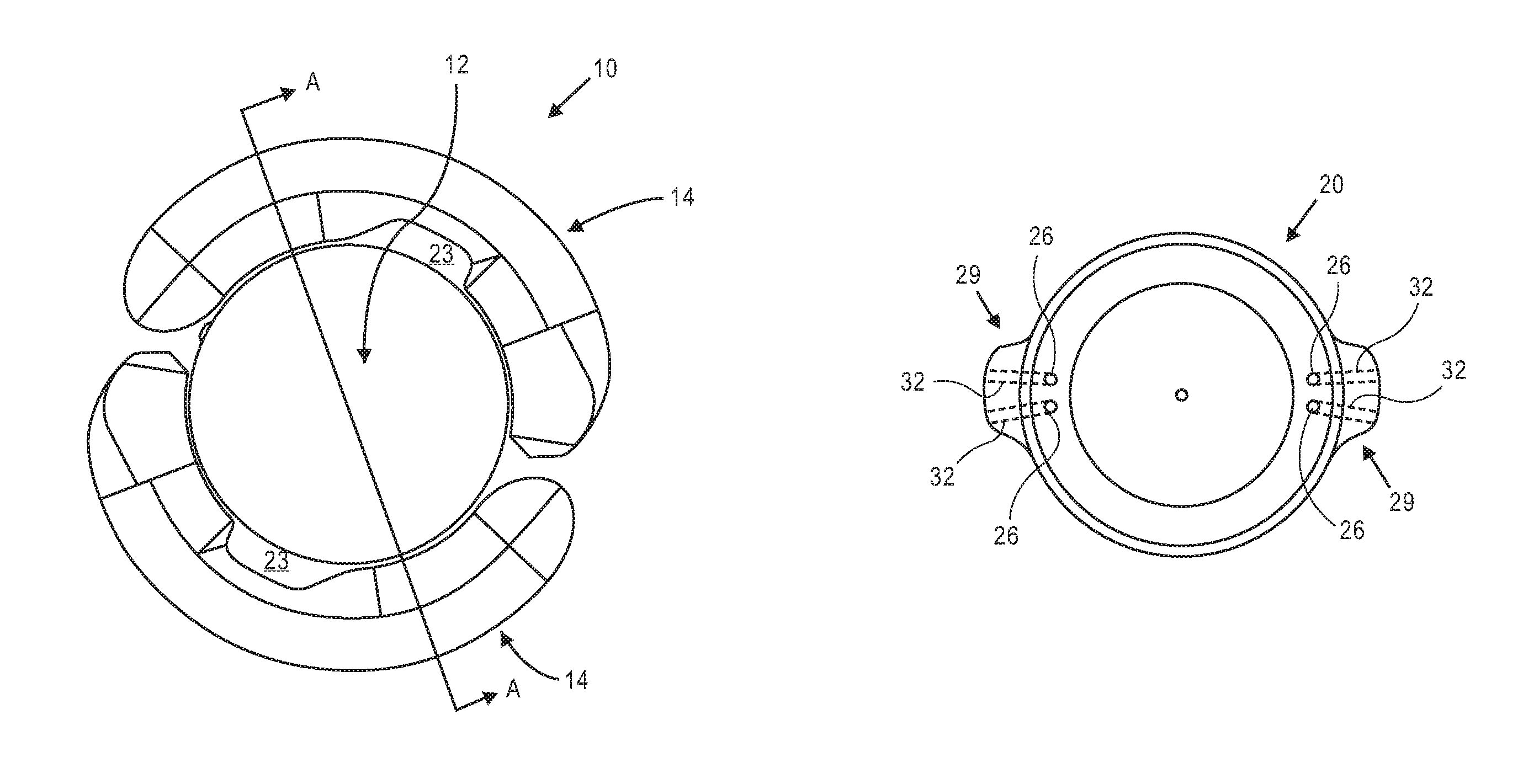
FIG. 1A is a top view illustrating accommodating intraocular lens 10 that includes optic portion 12 and a peripheral portion that in this embodiment includes first and second haptics 14 coupled to and extending peripherally from optic portion 12. Optic portion 12 is adapted to refract light that enters the eye onto the retina. Haptics 14 are configured to engage a capsular bag and are adapted to deform in response to ciliary muscle related capsular bag reshaping. FIG. 1B is a perspective view of intraocular lens 10 showing optic portion 12 and haptics 14 coupled to optic portion 12.
The haptics are in fluid communication with the optic portion. Each haptic has a fluid chamber that is in fluid communication with an optic chamber in the optic portion. The haptics are formed of a deformable material and are adapted to engage the capsular bag and deform in response to ciliary muscle related capsular bag reshaping. When the haptics deform the volume of the haptic fluid chamber changes, causing a fluid disposed in the haptic fluid chambers and the optic fluid chamber to either move into the optic fluid chamber from the haptic fluid chambers, or into the haptic fluid chambers from the optic fluid chamber. When the volume of the haptic fluid chambers decreases, the fluid is moved into the optic fluid chamber. When the volume of the haptic fluid chamber increases, fluid is moved into the haptic fluid chambers from the optic fluid chamber. The fluid flow into and out of the optic fluid chamber changes the configuration of the optic portion and the power of the intraocular lens.
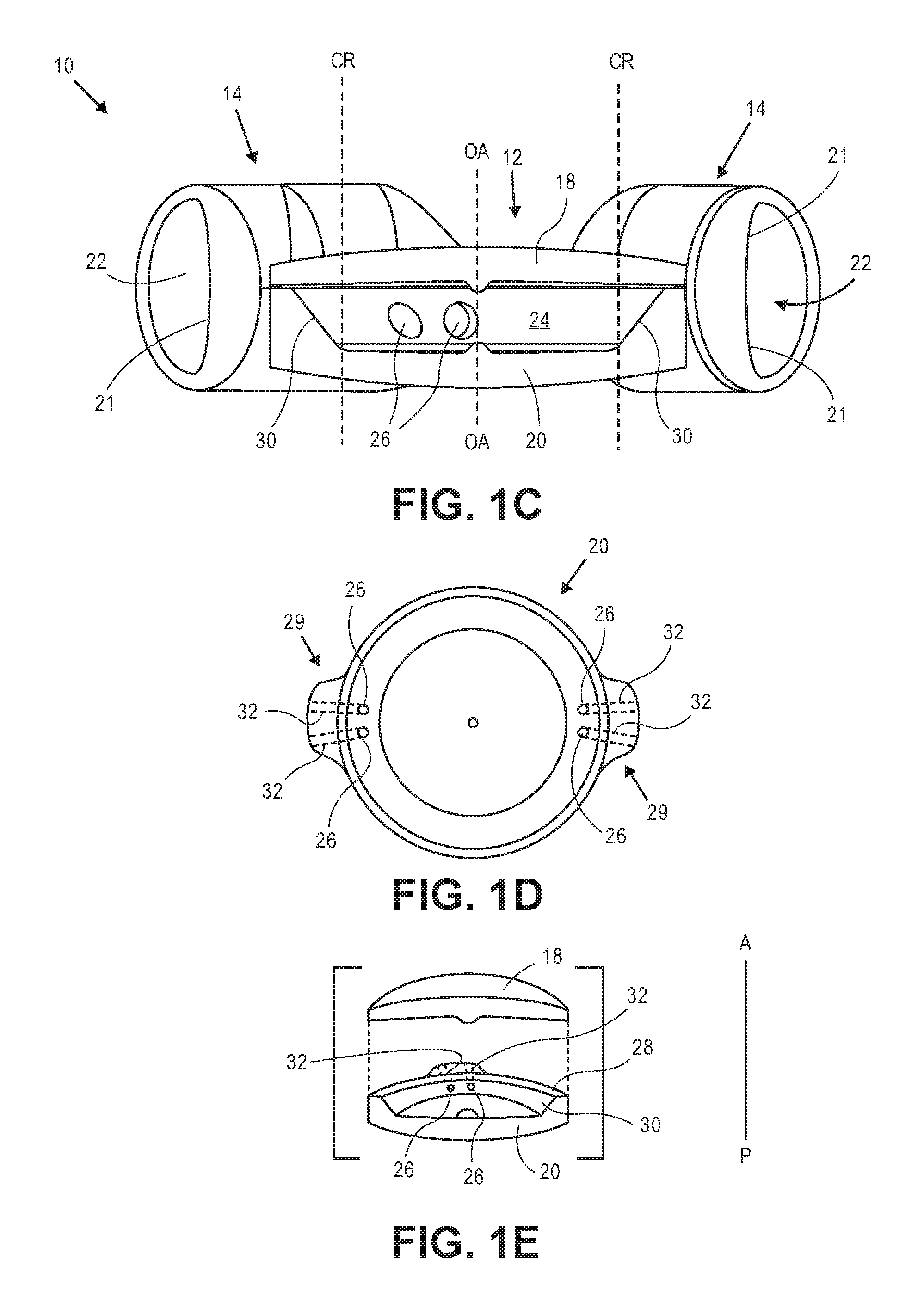
FIG. 1C is a side sectional view through Section A-A indicated in FIG. 1A. Optic portion 12 includes deformable anterior element 18 secured to deformable posterior element 20. Each haptic 14 includes a fluid chamber 22 that is in fluid communication with optic fluid chamber 24 in optic portion 12. Only the coupling between the haptic 14 to the left in the figure and option portion 12 is shown (although obscured) in the sectional view of FIG. 1C. The haptic fluid chamber 22 to the left in the figure is shown in fluid communication with optic fluid chamber 24 via two apertures 26, which are formed in posterior element 20. The haptic 14 to the right in FIG. 1C is in fluid communication with optic chamber 24 via two additional apertures also formed in posterior element (not shown) substantially 180 degrees from the apertures shown.
FIG. 1D is a top view of posterior element 20 (anterior element 18 and haptics 14 not shown). Posterior element 20 includes buttress portions 29 in which channels 32 are formed. Channels 32 provide fluid communication between optic portion 12 and haptics 14. Apertures 26 are disposed at one end of channels 32. The optic fluid chamber 24 is therefore in fluid communication with a single haptic via two fluid channels. Buttress portions 29 are configured and sized to be disposed within an opening formed in haptics 14 that defines one end of the haptic fluid chamber, as described below. Each of buttress portions 29 includes two channels formed therein. A first channel in a first buttress is in alignment with a first channel in the second buttress. The second channel in the first buttress is in alignment with the second channel in the second buttress.
There are advantages to having two channels in each buttress as opposed to one channel. A design with two channels rather than one channel helps maintain dimensional stability during assembly, which can be important when assembling flexible and thin components. Additionally, it was observed through experimentation that some one-channel designs did not provide adequate optical quality throughout the range of accommodation. In particular, lens astigmatism was observed in some one-channel designs, particularly as the intraocular lens accommodated. It was discovered that the two-channel buttress designs described herein reduced astigmatism, particularly as the lens accommodated. Astigmatism is reduced in these embodiments because the stiffness of the buttress is increased by the rib portion between the two channels. The additional stiffness results in less deflection due to pressure changes in the channels. Less deflection due to the pressure changes in the channels results in less astigmatism. In some embodiments the channels are between about 0.4 mm and about 0.6 mm in diameter. In some embodiments the channels are about 0.5 mm in diameter. In some embodiments the distance between the apertures is about 0.1 mm to about 1.0 mm.
FIG. 1E is a side assembly view through section A-A of optic portion 12, which includes anterior element 18 and posterior element 20 (haptics not shown for clarity). By including fluid channels 32 in posterior element 20, posterior element 20 needs to have enough structure through which the channels 32 can be formed. Buttress portions 29 provide that structures in which channels 32 can be formed. At its peripheral-most portion posterior element 20 is taller than anterior element 18 in the anterior-to-posterior direction. In alternative embodiments, the channels can be formed in anterior element 18 rather than posterior element 20. The anterior element would include buttress portions 29 or other similar structure to provide structure in which the channels can be formed. In these alternative embodiments the posterior element could be formed similarly to anterior element 18.
As shown in FIG. 1E, posterior element 20 is secured to anterior element 18 at peripheral surface 28, which extends around the periphery of posterior element 20 and is a flat surface. Elements 18 and 20 can be secured together using known biocompatible adhesives. Anterior element 18 and posterior element 20 can also be formed from one material to eliminate the need to secure two elements together. In some embodiments the diameter of the region at which anterior element 18 and posterior element 20 are secured to one another is about 5.4 mm to about 6 mm in diameter.
In some embodiments the thickness of anterior element 18 (measured in the anterior-to-posterior direction) is greater along the optical axis ("OA" in FIG. 1C) than at the periphery. In some embodiments the thickness increases continuously from the periphery towards the thickest portion along the optical axis.
In some embodiments the thickness of posterior element 20 decreases from the location along the optical axis towards the edge of central region "CR" identified in FIG. 1C. The thickness increases again radially outward of central region CR towards the periphery, as can be seen in FIG. 1C. In some particular embodiments central region CR is about 3.75 mm in diameter. The apertures are formed in beveled surface 30.
In some embodiments the thickness of posterior element 20 along the optical axis is between about 0.45 mm and about 0.55 mm and the thickness at the periphery of posterior element 20 is between about 1.0 mm and about 1.3.
In some embodiments the thickness of posterior element 20 along the optical axis is about 0.5 mm and the thickness at the periphery of posterior element 20 is about 1.14 mm.
In some embodiments the thickness of anterior element 18 along the optical axis is between about 0.45 mm to about 0.55 mm, and in some embodiments is between about 0.50 mm to about 0.52 mm. In some embodiments the thickness at the periphery of anterior element 18 is between about 0.15 mm and about 0.4 mm, and in some embodiments is between about 0.19 mm and about 0.38 mm.
In one particular embodiment the thickness of anterior element 18 along the optical axis is about 0.52 mm and the thickness of the periphery of anterior element 18 is about 0.38 mm, and the thickness of posterior element 20 along the optical axis is about 0.5 mm and the thickness at the periphery of posterior element 20 is about 1.14 mm.
In one particular embodiment the thickness of anterior element 18 along the optical axis is about 0.5 mm and the thickness of the periphery of anterior element 18 is about 0.3 mm, and the thickness of posterior element 20 along the optical axis is about 0.5 mm and the thickness at the periphery of posterior element 20 is about 1.14 mm.
In one particular embodiment the thickness of anterior element 18 along the optical axis is about 0.51 mm and the thickness of the periphery of anterior element 18 is about 0.24 mm, and the thickness of posterior element 20 along the optical axis is about 0.5 mm and the thickness at the periphery of posterior element 20 is about 1.14 mm.
In one particular embodiment the thickness of anterior element 18 along the optical axis is about 0.52 mm and the thickness of the periphery of anterior element 18 is about 0.19 mm, and the thickness of posterior element 20 along the optical axis is about 0.5 mm and the thickness at the periphery of posterior element 20 is about 1.14 mm.
The optic portion is adapted to maintain optical quality throughout accommodation. This ensures that as the accommodating intraocular lens transitions between the dis-accommodated and accommodated configurations, the optic portion maintains optical quality. A number of factors contribute to this beneficial feature of the accommodating intraocular lenses herein. These factors include the peripheral region at which anterior element 18 is secured to posterior element 20, the shape profile of the anterior element 18 and posterior element 20 inside central region CR of the optic portion (see FIG. 1C), and the thickness profiles of anterior element 18 and posterior element 20. These contributing factors ensure that both the anterior and posterior elements flex in such a way as to maintain the shape necessary to maintain optical quality across a range of optical powers.
FIG. 1F illustrates one haptic 14 from intraocular lens 10 (optic portion 12 and the second haptic not shown for clarity). Haptic 14 includes radially outer portion 13 adapted to face the direction of the zonules, and radially inner portion 11, which faces the periphery of the optic (not shown). Haptic 14 includes a first end region 17 which is secured to optic portion 12, and second end region 19 that is closed. Haptic 14 also includes opening 15 in first end region 17 that provides the fluid communication with the haptic. In this embodiment opening 15 is sized and configured to receive buttress portion 29 of optic portion 12 therein.
FIG. 1G is a close up view of opening 15 in haptic 14, which is adapted to receive buttress portion 29 therein. The opening 15 has curved surfaces 33 and 35 that are shaped to mate with curved surfaces on the optic buttress 29. Surface 31 surrounds opening 15 and provides a surface to which a corresponding surface of the optic can be secured.
FIG. 1H is a top close up view of buttress portion 29 (in phantom) from posterior element 20 disposed within opening 15 in haptic 14 (anterior element of the optic not shown for clarity). Channels 32 are shown in phantom. Haptic 14 includes fluid chamber 22 defined by inner surface 21. Fluid moves between the optic fluid chamber and haptic fluid chamber 22 through channels 32 upon the deformation of haptic 14.
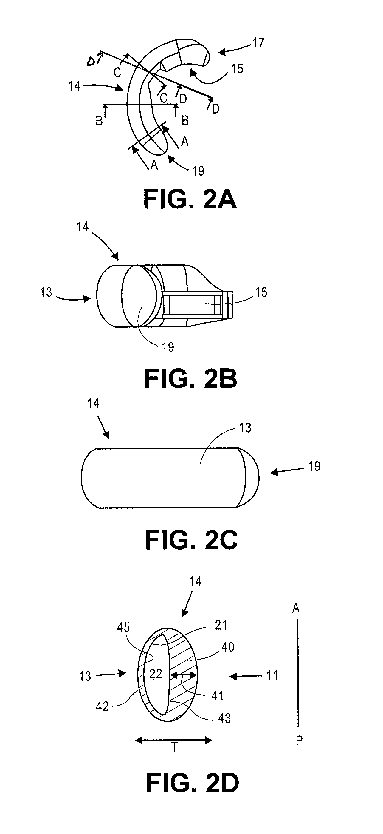
FIG. 2A is a top view showing one haptic 14 shown in FIGS. 1A-1H. The optic portion and the second haptic are not shown. Four sections A-D are identified through the haptic. FIG. 2B illustrates a side view of haptic 14, showing opening 15 and closed end 19. FIG. 2C is a side view of haptic 14 showing radially outer portion 13 and closed end 19.
FIG. 2D is the cross sectional view through section A-A shown in FIG. 2A. Of the four sections shown in FIG. 2A, section A-A is the section closest to closed end 19. Radially inner portion 11 and radially outer portion 13 are identified. Fluid channel 22 defined by surface 21 is also shown. In this section the radially inner portion 40 is radially thicker (in the direction "T") than radially outer portion 42. Inner portion 40 provides the haptic's stiffness in the anterior-to-posterior direction that more predictably reshapes the capsule in the anterior-to-posterior direction. Radially inner portion 40 has a greatest thickness dimension 41, which is along an axis of symmetry in this cross section. The outer surface of haptic 14 has a generally elliptical configuration in which the greatest height dimension, in the anterior-to-posterior direction ("A-P"), is greater than the greatest thickness dimension (measured in the "T" dimension). The fluid chamber 22 has a general D-shaped configuration, in which the radially inner wall 43 is less curved (but not perfectly linear) than radial outer wall 45. Radially outer portion 42 engages the capsular bag where the zonules attach thereto, whereas the thicker radially portion 40 is disposed adjacent the optic.
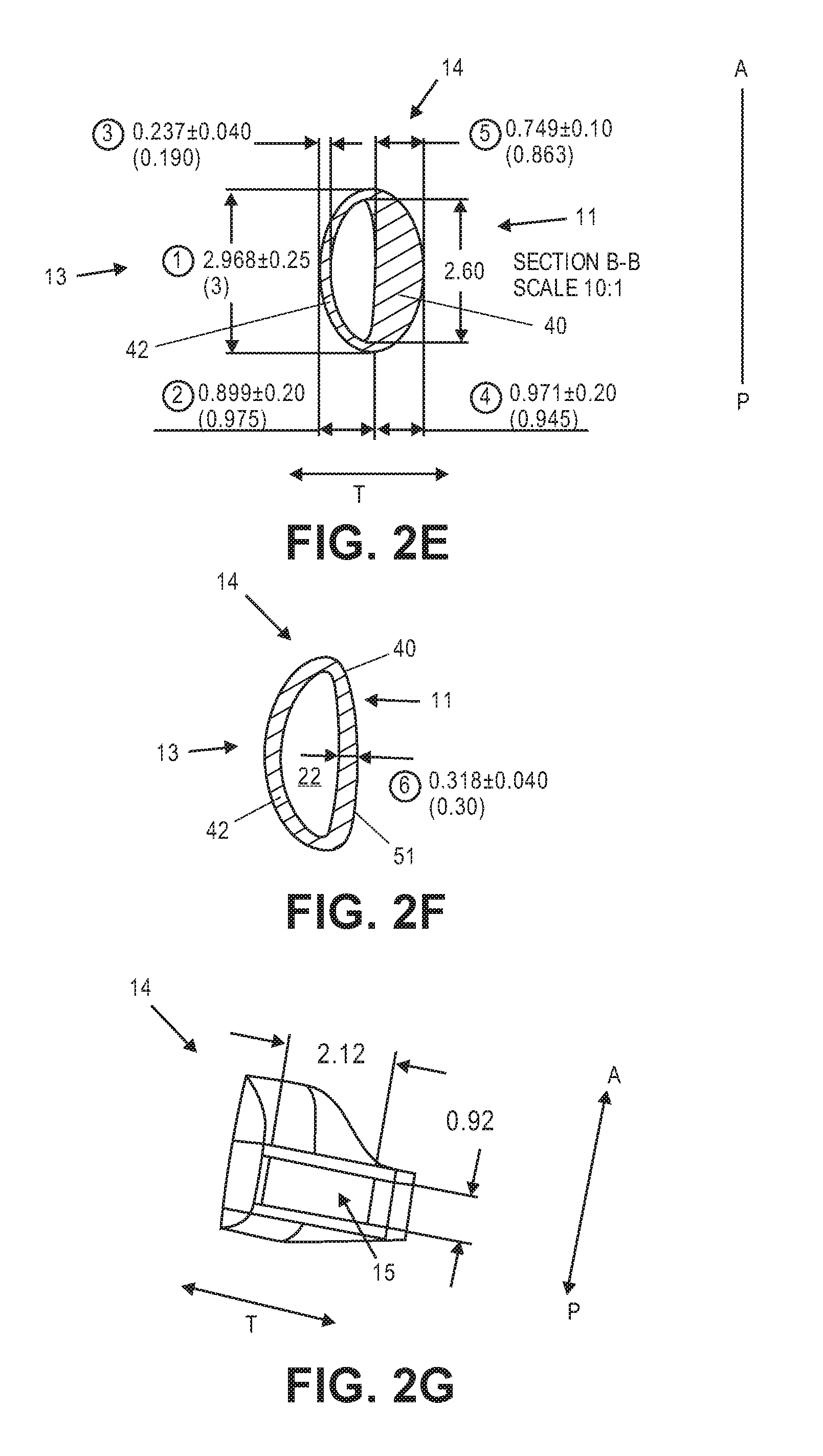
FIG. 2E illustrates section B-B shown in FIG. 2A. Section B-B is substantially the same as section A-A, and FIG. 2E provides exemplary dimensions for both sections. Radially inner portion 40 has a greatest thickness along the midline of about 0.75 mm (in the radial direction "T"). Radially outer portion 42 has a thickness along the midline of about 0.24 mm. Fluid chamber 22 has a thickness of about 0.88 mm. Haptic 14 has a thickness along the midline of about 1.87 mm. The height of the haptic in the anterior to posterior dimension is about 2.97 mm. The height of the fluid chamber is about 2.60 mm. In this embodiment the thickness of the radially inner portion 40 is about 3 times the thickness of the radially outer portion 42. In some embodiments the thickness of the radially inner portion 40 is about 2 times the thickness of the radially outer portion 42. In some embodiments the thickness of the radially inner portion 40 is about 2 to about 3 times the thickness of the radially outer portion 42. In some embodiments the thickness of the radially inner portion 40 is about 1 to about 2 times the thickness of the radially outer portion 42.
Fluid chamber 22 is disposed in the radially outer portion of haptic 14. Substantially the entire radially inner region of haptic 14 in this section is bulk material. Since the fluid chamber 22 is defined by surfaces 43 and 45 (see FIG. 2D), the positioning and size of fluid chamber 22 depends on the thickness of the radially inner portion 40 and the radially outer portion 42.
FIG. 2F illustrates Section C-C shown in FIG. 2A. In Section C-C radially inner portion 40 is not as thick as radially inner portion 40 in sections A-A and B-B, although in Section C-C radially inner portion 40 is slightly thicker than radially outer portion 42. In this particular embodiment radially inner portion 40 is about 0.32 mm in Section C-C. Radially outer portion 42 has a thickness about the same as the radially outer thickness in Sections A-A and B-B, about 0.24 mm. The outer surface of haptic 14 does not have the same configuration as the outer surface in Sections A-A and Section B-B. In Section C-C the radially inner outer surface of haptic 51 is more linear than in Sections A-A and Section B-B, giving the outer surface of haptic in Section C-C a general D-shape. In Section C-C fluid chamber 22 has a general D-shape, as in Sections A-A and Section B-B. The haptic, in Section C-C has a fluid chamber configuration that is substantially the same as the fluid chamber configurations in Sections A-A and B-B, but has an outer surface with a configuration different than the configuration of the outer surface of haptic 14 in Sections A-A and B-B.
The thinner radially inner portion 40 in Section C-C also creates access pathways 23 that are shown in FIG. 1A. This space between optic portion 12 and haptics 14 allows a physician to insert one or more irrigation and/or aspiration devices into space 23 during the procedure and apply suction to remove viscoelastic fluid that may be used in the delivery of the intraocular lens into the eye. The pathways 23 could also be anywhere along the length of the haptic, and there could be more than one pathway 23. This application incorporates by reference the disclosure in FIGS. 23 and 24, and the textual description thereof, from U.S. Pub. No. 2008/0306588, which include a plurality of pathways in the haptics.
FIG. 2G shows a view through Section D-D from FIG. 2A. Haptic 14 includes opening 15 therein, which is adapted to receive the buttress from the optic portion as described herein. The height of opening 15 in this embodiment is about 0.92 mm. The width, or thickness, of the opening is about 2.12 mm.
FIG. 3 illustrates relative diameters of optic portion 12 (not shown) and of the peripheral portion, which includes two haptics 14 (only one haptic is shown). In this embodiment the optic has a diameter of about 6.1 cm, while the entire accommodating intraocular lens, including the peripheral portion, has a diameter of about 9.95 cm. The dimensions provided are not intended to be strictly limiting.
FIG. 4 is a top view of haptic 14, showing that haptic 14 subtends an angle of about 175 degrees around optic (i.e., substantially 180 degrees). The optic portion is not shown for clarity. The two haptics therefore each subtend an angle of about 180 degrees around the optic. A first region 61 of haptic 14 is shown to subtend exemplary angle of about 118 degrees. This is the radially outermost portion of haptic 14, is adapted to engage the capsular bag, and is adapted to be most responsive to capsular shape changes. Region 61 can be thought of as the most responsive part of haptic 14.
The angle between Sections A-A and B-B, which are considered the boundaries of the stiffer radially inner portion of the haptic, is about 40 degrees. The stiff radially inner portion of haptic 14 is positioned directly adjacent the periphery of the optic. The dimensions and angles provided are not intended to be strictly limiting.
FIGS. 5A and 5B illustrate a portion of accommodating intraocular lens 10 positioned in a capsular bag ("CB") after a native lens has been removed from the CB. The anterior direction is on top and the posterior direction is on bottom in each figure. FIG. 5A shows the accommodating intraocular lens in a lower power, or dis-accommodated, configuration relative to the high power, or accommodated, configuration shown in FIG. 5B.
The elastic capsular bag "CB" is connected to zonules "Z," which are connected to ciliary muscles "CM." When the ciliary muscles relax, as shown in FIG. 5A, the zonules are stretched. This stretching pulls the capsular bag in the generally radially outward direction due to radially outward forces "R" due to the general equatorial connection location between the capsular bag and the zonules. The zonular stretching causes a general elongation and thinning of the capsular bag. When the native lens is still present in the capsular bag, the native lens becomes flatter (in the anterior-to-posterior direction) and taller in the radial direction, which gives the lens less power. Relaxation of the ciliary muscle, as shown in FIG. 5A, provides for distance vision. When the ciliary muscles contract, however, as occurs when the eye is attempting to focus on near objects, the radially inner portion of the muscles move radially inward, causing the zonules to slacken. This is illustrated in FIG. 5B. The slack in the zonules allows the capsular bag to move towards a generally more curved configuration in which the anterior surface has greater curvature than in the disaccommodated configuration, providing higher power and allowing the eye to focus on near objects. This is generally referred to as "accommodation," and the lens is said to be in an "accommodated" configuration.
In section A-A (which is the same as section B-B) of haptic 14, illustrated in FIGS. 5A and 5B, radially inner portion 40 includes thicker bulk material that provides haptic 14 with stiffness in the anterior-to-posterior direction. When capsular bag forces are applied to the haptic in the anterior-to-posterior direction, the inner portion 40, due to its stiffness, deforms in a more repeatable and predictable manner making the base state of the lens more predictable. Additionally, the haptic, due to its stiffer inner portion, deforms the capsule in a repeatable way in the anterior-to-posterior direction. Additionally, because the haptic is less flexible along the length of the haptic, the accommodating intraocular lens's base state is more predictable because bending along the length of the haptic is one way in which fluid can be moved into the optic (and thereby changing the power of the lens). Additional advantages realized with the stiffer inner portion are that the haptics are stiffer to other forces such as torqueing and splaying because of the extra bulk in the inner portion.
The radially outer portion 42 is the portion of the haptic that directly engages the portion of the capsular bag that is connected to the zonules. Outer portion 42 of the haptics is adapted to respond to capsular reshaping forces "R" that are applied generally radially when the zonules relax and stretch. This allows the haptic to deform in response to ciliary muscle related forces (i.e., capsular contraction and relaxation) so that fluid will flow between the haptic and the optic in response to ciliary muscle relaxation and contraction. This is illustrated in FIG. 5B. When the ciliary muscles contract (FIG. 5B), the peripheral region of the elastic capsular bag reshapes and applies radially inward forces "R" on radially outer portion 42 of haptic 14. The radially outer portion 42 is adapted to deform in response to this capsular reshaping. The deformation decreases the volume of fluid channel 22, which forces fluid from haptic chamber 22 into optic chamber 24. This increases the fluid pressure in optic chamber 42. The increase in fluid pressure causes flexible anterior element 18 and flexible posterior element 20 to deform, increasing in curvature, and thus increasing the power of the intraocular lens.
The haptic is adapted to be stiffer in the anterior-to-posterior direction than in the radial direction. In this embodiment the radially outer portion 42 of haptic 14 is more flexible (i.e., less stiff) in the radial direction than the stiffer inner portion 40 is in the anterior-to-posterior direction. This is due to the relative thicknesses of outer portion 42 and inner portion 40. The haptic is thus adapted to deform less in response to forces in the anterior-to-posterior direction than to forces in the radial direction. This also causes less fluid to be moved from the haptic into the optic in response to forces in the anterior-to-posterior direction than is moved into the optic in response to forces in the radial direction. The haptic will also deform in a more predictable and repeatable manner due to its stiffer radially inner portion.
The peripheral portion is thus more sensitive to capsular bag reshaping in the radial direction than to capsular bag reshaping in the anterior-to-posterior direction. The haptics are adapted to deform to a greater extent radially than they are in the anterior-to-posterior direction. The disclosure herein therefore includes a peripheral portion that is less sensitive to capsular forces along a first axis, but is more sensitive to forces along a second axis. In the example above, the peripheral portion is less sensitive along the posterior-to-anterior axis, and is more sensitive in the radial axis.
An exemplary benefit of the peripheral portions described above is that they deform the capsular bag in a repeatable way and yet maintain a high degree of sensitivity to radial forces during accommodation. The peripheral portions described above are stiffer in the anterior-to-posterior direction than in the radial direction.
An additional example of capsular forces in the anterior-to-posterior direction is capsular forces on the peripheral portion after the accommodating intraocular lens is positioned in the capsular bag, and after the capsular bag generally undergoes a healing response. The healing response generally causes contraction forces on the haptic in the anterior-to-posterior direction, identified in FIG. 5A by forces "A." These and other post-implant, such as non-accommodating-related, capsular bag reshaping forces are described in U.S. application Ser. No. 12/685,531, filed Jan. 11, 2010, which is incorporated herein by reference. For example, there is some patient to patient variation in capsular bag size, as is also described in detail in U.S. application Ser. No. 12/685,531, filed Jan. 11, 2010. When an intraocular lens is positioned within a capsular bag, size differences between the capsule and intraocular lens may cause forces to be exerted on one or more portions of the intraocular lens in the anterior-to-posterior direction.
In the example of capsular healing forces in the anterior-to-posterior direction, the forces may be able to deform a deformable haptic before any accommodation occurs. This deformation changes the volume of the haptic fluid chamber, causing fluid to flow between the optic fluid chamber and the haptic fluid chambers. This can, in some instances undesirably, shift the base power of the lens. For example, fluid can be forced into the optic upon capsular healing, increasing the power of the accommodating intraocular lens, and creating a permanent myopic shift for the accommodating intraocular lens. Fluid could also be forced out of the optic and into the haptics, decreasing the power of the accommodating intraocular lens.
As used herein, "radial" need not be limited to exactly orthogonal to the anterior-to-posterior plane, but includes planes that are 45 degrees from the anterior-to-posterior plane.
Exemplary fluids are described in U.S. application Ser. No. 12/685,531, filed Jan. 11, 2010, and in U.S. application Ser. No. 13/033,474, filed Feb. 23, 2011, now U.S. Pat. No. 8,900,298, which are incorporated herein by reference. For example, the fluid can be a silicone oil that is or is not index-matched with the polymeric materials of the anterior and posterior elements. When using a fluid that is index matched with the bulk material of the optic portion, the entire optic portion acts a single lens whose outer curvature changes with increases and decreases in fluid pressure in the optic portion.
In the embodiment in FIGS. 2A-2G above the haptic is a deformable polymeric material that has a substantially uniform composition in Sections A-A, B-B, and C-C. The stiffer radially inner body portion 40 is attributed to its thickness. In alternative embodiments the radially inner body portion has a different composition that the outer body portion, wherein the radially inner body portion material is stiffer than the material of the radially outer body portion. In these alternative embodiments the thicknesses of the radially inner and outer portions can be the same.
FIG. 6 illustrates haptic 50, which is the same haptic configuration as in shown in FIG. 2B. The radially outer portion 54 is identified. The haptic has axis A-A halfway through the height of the haptic. Opening 52, in which the optic buttress is disposed, is on the posterior side of axis A. In this embodiment the optic sits slightly closer to the posterior-most portion of the haptics than the anterior-most portion of the haptics.
FIG. 7 illustrates an alternative haptic 60 (optic not shown), wherein the radially outer portion 64 is identified. Haptic 60 includes axis A-A halfway through the thickness of the haptic. Opening 62 is symmetrical about the axis A. Additionally, axis A-A is an axis of symmetry for haptic 60. The symmetry of the haptic along axis A can improve the ability to mold low relatively low stress components. FIG. 8 shows an embodiment of intraocular lens 70 in which the optic 72 is coupled to two haptics 60, which are the haptics shown in FIG. 7. The optic sits further in the anterior direction that in the embodiment in which the opening is not along the midline of the haptic. The cross sections A-A, B-B, and C-C of haptic 60 are the same as those shown in other embodiments shown above.
FIG. 9 illustrates intraocular lens 80 including optic 82 and two haptics 84. The optic is the same as the optic portions described herein. Haptics 84 are not as tall, measured in the anterior-to-posterior direction, as haptic 60, haptic 50, or haptic 14. In exemplary embodiments haptics 84 are between about 2.0 mm and about 3.5 mm tall, and in some embodiments they are about 2.8 mm tall. Intraocular lens 80 can be considered a size "small" accommodating intraocular lens for patients with a capsular bag that is below a certain threshold size. The posterior surface of posterior element 86 is disposed slightly further in the posterior direction than the posterior-most portions 90 of haptics 84.
Characteristics of the intraocular lenses described herein can similarly be applied to non-fluid driven accommodating intraocular lenses. For example, a non-accommodating intraocular lens can include a peripheral portion with a first stiffer region that provides a region of the peripheral portion with an insensitivity in a first direction. For example, in an intraocular lens with two lenses adapted to be moved apart from one another to change the power of the lens, the peripheral portion of the lens can be adapted such that a first type of capsular reshaping does not cause the distance between the lenses to change, and thus the power of the intraocular lens stays the same.
Additionally, the accommodating intraocular lenses herein can also be adapted to be positioned outside of a native capsular bag. For example, the accommodating intraocular lenses can be adapted to be positioned in front of, or anterior to, the capsular bag after the native lens has been removed or while the native lens is still in the capsular bag, wherein the peripheral portion of the lens is adapted to respond directly with ciliary muscle rather than rely on capsular reshaping.
* * * * *
D00000
D00001
D00002
D00003
D00004
D00005
D00006
D00007
D00008
D00009
XML
uspto.report is an independent third-party trademark research tool that is not affiliated, endorsed, or sponsored by the United States Patent and Trademark Office (USPTO) or any other governmental organization. The information provided by uspto.report is based on publicly available data at the time of writing and is intended for informational purposes only.
While we strive to provide accurate and up-to-date information, we do not guarantee the accuracy, completeness, reliability, or suitability of the information displayed on this site. The use of this site is at your own risk. Any reliance you place on such information is therefore strictly at your own risk.
All official trademark data, including owner information, should be verified by visiting the official USPTO website at www.uspto.gov. This site is not intended to replace professional legal advice and should not be used as a substitute for consulting with a legal professional who is knowledgeable about trademark law.