Marking device with retractable cannula
Field , et al. July 23, 2
U.S. patent number 10,357,328 [Application Number 10/907,906] was granted by the patent office on 2019-07-23 for marking device with retractable cannula. This patent grant is currently assigned to Bard Peripheral Vascular, Inc. and Bard Shannon Limited. The grantee listed for this patent is Richard M. Chesbrough, Richard E. Davis, Steven E. Field, Ryan L. Goosen. Invention is credited to Richard M. Chesbrough, Richard E. Davis, Steven E. Field, Ryan L. Goosen.


View All Diagrams
| United States Patent | 10,357,328 |
| Field , et al. | July 23, 2019 |
Marking device with retractable cannula
Abstract
A marking device according to one embodiment of the invention comprises a handle, a cannula having a cannula distal end and slidably mounted to the handle, and a stylet having a stylet distal end and slidably mounted to the handle in the cannula. The stylet distal end is spaced proximally of the cannula distal end to form a marker recess that receives an imaging marker. The marking device further comprises an actuator operably coupled to the cannula to effect retraction of the cannula into the handle following implantation of the imaging marker. The imaging marker can be implanted by advancing the stylet relative to the cannula to eject the imaging marker from the marker recess, or the cannula can be retracted relative to the stylet to expose the imaging marker.
| Inventors: | Field; Steven E. (Grand Rapids, MI), Goosen; Ryan L. (Coopersville, MI), Davis; Richard E. (Grand Rapids, MI), Chesbrough; Richard M. (Bloomfield Hills, MI) | ||||||||||
|---|---|---|---|---|---|---|---|---|---|---|---|
| Applicant: |
|
||||||||||
| Assignee: | Bard Peripheral Vascular, Inc. and
Bard Shannon Limited (Franklin Lakes, NJ) |
||||||||||
| Family ID: | 36643354 | ||||||||||
| Appl. No.: | 10/907,906 | ||||||||||
| Filed: | April 20, 2005 |
Prior Publication Data
| Document Identifier | Publication Date | |
|---|---|---|
| US 20060241411 A1 | Oct 26, 2006 | |
| Current U.S. Class: | 1/1 |
| Current CPC Class: | A61B 90/39 (20160201); A61B 2090/3987 (20160201); A61B 2090/3908 (20160201); A61B 2090/0801 (20160201) |
| Current International Class: | A61B 90/00 (20160101) |
| Field of Search: | ;604/61 ;600/424,431,130,7 ;128/897 |
References Cited [Referenced By]
U.S. Patent Documents
| 2192270 | March 1940 | McGowan |
| 2481408 | September 1949 | Fuller et al. |
| 2832888 | April 1958 | Houston |
| 2899362 | August 1959 | Sieger, Jr. et al. |
| 2907327 | October 1959 | White |
| 3005457 | October 1961 | Millman |
| 3128744 | April 1964 | Jefferts et al. |
| 3341417 | September 1967 | Sinaiko |
| 3402712 | September 1968 | Eisenhand |
| 3516412 | June 1970 | Ackerman |
| 3593343 | July 1971 | Viggers |
| 3757781 | September 1973 | Smart |
| 3818894 | June 1974 | Wichterle et al. |
| 3820545 | June 1974 | Jefferts |
| 3823212 | July 1974 | Chvapil |
| 3921632 | November 1975 | Bardani |
| 4005699 | February 1977 | Bucalo |
| 4007732 | February 1977 | Kvavle et al. |
| 4041931 | August 1977 | Elliot et al. |
| 4086914 | May 1978 | Moore |
| 4103690 | August 1978 | Harris |
| 4105030 | August 1978 | Kercso |
| 4127774 | November 1978 | Gillen |
| 4172449 | October 1979 | LeRoy et al. |
| 4197846 | April 1980 | Bucalo |
| 4217889 | August 1980 | Radovan et al. |
| 4276885 | July 1981 | Tickner et al. |
| 4294241 | October 1981 | Miyata |
| 4298998 | November 1981 | Naficy |
| 4331654 | May 1982 | Morris |
| 4347234 | August 1982 | Wahlig et al. |
| 4390018 | June 1983 | Zukowski |
| 4400170 | August 1983 | McNaughton et al. |
| 4401124 | August 1983 | Guess et al. |
| 4405314 | September 1983 | Cope |
| 4428082 | January 1984 | Naficy |
| 4438253 | March 1984 | Casey et al. |
| 4442843 | April 1984 | Rasor et al. |
| 4470160 | September 1984 | Cavon |
| 4487209 | December 1984 | Mehl |
| 4545367 | October 1985 | Tucci |
| 4549560 | October 1985 | Andis |
| 4582061 | April 1986 | Fry |
| 4582640 | April 1986 | Smestad et al. |
| 4588395 | May 1986 | Lemelson |
| 4597753 | July 1986 | Turley |
| 4647480 | March 1987 | Ahmed |
| 4655226 | April 1987 | Lee |
| 4661103 | April 1987 | Harman |
| 4682606 | July 1987 | DeCaprio |
| 4693237 | September 1987 | Hoffman et al. |
| 4718433 | January 1988 | Feinstein |
| 4740208 | April 1988 | Cavon |
| 4762128 | August 1988 | Rosenbluth |
| 4813062 | March 1989 | Gilpatrick |
| 4820267 | April 1989 | Harman |
| 4832680 | May 1989 | Haber et al. |
| 4832686 | May 1989 | Anderson |
| 4847049 | July 1989 | Yamamoto |
| 4863470 | September 1989 | Carter |
| 4870966 | October 1989 | Dellon et al. |
| 4874376 | October 1989 | Hawkins, Jr. |
| 4889707 | December 1989 | Day et al. |
| 4909250 | March 1990 | Smith |
| 4931059 | June 1990 | Markham |
| 4938763 | July 1990 | Dunn et al. |
| 4950234 | August 1990 | Fujioka et al. |
| 4950665 | August 1990 | Floyd |
| 4963150 | October 1990 | Brauman |
| 4970298 | November 1990 | Silver et al. |
| 4989608 | February 1991 | Ratner |
| 4994013 | February 1991 | Suthanthiran et al. |
| 4994028 | February 1991 | Leonard et al. |
| 5012818 | May 1991 | Joishy |
| 5013090 | May 1991 | Matsuura |
| 5018530 | May 1991 | Rank et al. |
| 5035891 | July 1991 | Runkel et al. |
| 5059197 | October 1991 | Urie et al. |
| 5081997 | January 1992 | Bosley, Jr. et al. |
| 5108421 | April 1992 | Fowler |
| 5120802 | June 1992 | Mares et al. |
| 5125413 | June 1992 | Baran |
| 5137928 | August 1992 | Erbel et al. |
| 5141748 | August 1992 | Rizzo |
| 5147295 | September 1992 | Stewart |
| 5147307 | September 1992 | Gluck |
| 5147631 | September 1992 | Glajch et al. |
| 5162430 | November 1992 | Rhee et al. |
| 5163896 | November 1992 | Suthanthiran et al. |
| 5195540 | March 1993 | Shiber |
| 5197482 | March 1993 | Rank et al. |
| 5197846 | March 1993 | Uno et al. |
| 5199441 | April 1993 | Hogle |
| 5201704 | April 1993 | Ray |
| 5219339 | June 1993 | Saito |
| 5221269 | June 1993 | Miller et al. |
| 5231615 | July 1993 | Endoh |
| 5234426 | August 1993 | Rank et al. |
| 5236410 | August 1993 | Granov et al. |
| 5242759 | September 1993 | Hall |
| 5250026 | October 1993 | Ehrlich et al. |
| 5271961 | December 1993 | Mathiowitz et al. |
| 5273532 | December 1993 | Niezink et al. |
| 5280788 | January 1994 | Janes et al. |
| 5281197 | January 1994 | Arias et al. |
| 5281408 | January 1994 | Unger |
| 5282781 | February 1994 | Liprie |
| 5284479 | February 1994 | de Jong |
| 5289831 | March 1994 | Bosley |
| 5290310 | March 1994 | Makower et al. |
| 5312435 | May 1994 | Nash et al. |
| 5320100 | June 1994 | Herweck et al. |
| 5320613 | June 1994 | Houge et al. |
| 5328955 | July 1994 | Rhee et al. |
| 5334216 | August 1994 | Vidal et al. |
| 5334381 | August 1994 | Unger |
| 5344640 | September 1994 | Deutsch et al. |
| 5353804 | October 1994 | Kornberg et al. |
| 5354623 | October 1994 | Hall |
| 5358514 | October 1994 | Schulman et al. |
| 5360416 | November 1994 | Ausherman et al. |
| 5366756 | November 1994 | Chesterfield et al. |
| 5368030 | November 1994 | Zinreich et al. |
| 5388588 | February 1995 | Nabai et al. |
| 5394875 | March 1995 | Lewis et al. |
| 5395319 | March 1995 | Hirsch et al. |
| 5405402 | April 1995 | Dye et al. |
| 5409004 | April 1995 | Sloan |
| 5417708 | May 1995 | Hall et al. |
| 5422730 | June 1995 | Barlow et al. |
| 5425366 | June 1995 | Reinhardt et al. |
| 5431639 | July 1995 | Shaw |
| 5433204 | July 1995 | Olson |
| 5449560 | September 1995 | Antheunis et al. |
| 5451406 | September 1995 | Lawin et al. |
| 5458643 | October 1995 | Oka et al. |
| 5460182 | October 1995 | Goodman et al. |
| 5469847 | November 1995 | Zinreich et al. |
| 5475052 | December 1995 | Rhee et al. |
| 5490521 | February 1996 | Davis et al. |
| 5494030 | February 1996 | Swartz et al. |
| 5499989 | March 1996 | LaBash |
| 5507807 | April 1996 | Shippert |
| 5508021 | April 1996 | Grinstaff et al. |
| 5514085 | May 1996 | Yoon |
| 5522896 | June 1996 | Prescott |
| 5538726 | July 1996 | Order |
| 5542915 | August 1996 | Edwards et al. |
| 5545180 | August 1996 | Le et al. |
| 5549560 | August 1996 | Van de Wijdeven |
| 5567413 | October 1996 | Klaveness et al. |
| RE35391 | December 1996 | Brauman |
| 5580568 | December 1996 | Greff et al. |
| 5585112 | December 1996 | Unger et al. |
| 5611352 | March 1997 | Kobren et al. |
| 5626611 | May 1997 | Liu et al. |
| 5628781 | May 1997 | Williams et al. |
| 5629008 | May 1997 | Lee |
| 5636255 | June 1997 | Ellis |
| 5643246 | July 1997 | Leeb et al. |
| 5646146 | July 1997 | Faarup et al. |
| 5651772 | July 1997 | Arnett |
| 5657366 | August 1997 | Nakayama |
| 5665092 | September 1997 | Mangiardi et al. |
| 5667767 | September 1997 | Greff et al. |
| 5669882 | September 1997 | Pyles |
| 5673841 | October 1997 | Schulze et al. |
| 5676146 | October 1997 | Scarborough |
| 5676925 | October 1997 | Klaveness et al. |
| 5688490 | November 1997 | Tournier et al. |
| 5690120 | November 1997 | Jacobsen et al. |
| 5695480 | December 1997 | Evans et al. |
| 5702128 | December 1997 | Maxim et al. |
| 5702682 | December 1997 | Thompson |
| 5702716 | December 1997 | Dunn et al. |
| 5716981 | February 1998 | Hunter et al. |
| 5747060 | May 1998 | Sackler et al. |
| 5749887 | May 1998 | Heske et al. |
| 5752974 | May 1998 | Rhee et al. |
| 5762903 | June 1998 | Park et al. |
| 5769086 | June 1998 | Ritchart et al. |
| 5776496 | July 1998 | Violante et al. |
| 5779647 | July 1998 | Chau et al. |
| 5782764 | July 1998 | Werne |
| 5782771 | July 1998 | Hussman |
| 5782775 | July 1998 | Milliman et al. |
| 5795308 | August 1998 | Russin |
| 5799099 | August 1998 | Wang et al. |
| 5800362 | September 1998 | Kobren et al. |
| 5800389 | September 1998 | Burney et al. |
| 5800445 | September 1998 | Ratcliff et al. |
| 5800541 | September 1998 | Rhee et al. |
| 5810884 | September 1998 | Kim |
| 5817022 | October 1998 | Vesely |
| 5820918 | October 1998 | Ronan et al. |
| 5821184 | October 1998 | Haines et al. |
| 5823198 | October 1998 | Jones et al. |
| 5824042 | October 1998 | Lombardi et al. |
| 5824081 | October 1998 | Knapp et al. |
| 5826776 | October 1998 | Schulze et al. |
| 5830178 | November 1998 | Jones et al. |
| 5830222 | November 1998 | Makower |
| 5842477 | December 1998 | Naughton et al. |
| 5842999 | December 1998 | Pruitt et al. |
| 5845646 | December 1998 | Lemelson |
| 5846220 | December 1998 | Elsberry |
| 5851508 | December 1998 | Greff et al. |
| 5853366 | December 1998 | Dowlatshahi |
| 5865806 | February 1999 | Howell |
| 5869080 | February 1999 | McGregor et al. |
| 5871501 | February 1999 | Leschinsky et al. |
| 5876340 | March 1999 | Tu et al. |
| 5879357 | March 1999 | Heaton et al. |
| 5891558 | April 1999 | Bell et al. |
| 5897507 | April 1999 | Kortenbach et al. |
| 5902310 | May 1999 | Foerster et al. |
| 5911705 | June 1999 | Howell |
| 5916164 | June 1999 | Fitzpatrick et al. |
| 5921933 | July 1999 | Sarkis et al. |
| 5922024 | July 1999 | Janzen et al. |
| 5928626 | July 1999 | Klaveness et al. |
| 5928773 | July 1999 | Andersen |
| 5941439 | August 1999 | Kammerer et al. |
| 5941890 | August 1999 | Voegele et al. |
| 5942209 | August 1999 | Leavitt et al. |
| 5948425 | September 1999 | Janzen et al. |
| 5954670 | September 1999 | Baker |
| 5972817 | October 1999 | Haines et al. |
| 5976146 | November 1999 | Ogawa et al. |
| 5980564 | November 1999 | Stinson |
| 5989265 | November 1999 | Bouquet De La Joliniere et al. |
| 6015541 | January 2000 | Greff et al. |
| 6030333 | February 2000 | Sioshansi et al. |
| 6053925 | April 2000 | Barnhart |
| 6056700 | May 2000 | Burney et al. |
| 6066122 | May 2000 | Fisher |
| 6066325 | May 2000 | Wallace et al. |
| 6071301 | June 2000 | Cragg et al. |
| 6071310 | June 2000 | Picha et al. |
| 6071496 | June 2000 | Stein et al. |
| 6090996 | July 2000 | Li |
| 6096065 | August 2000 | Crowley |
| 6096070 | August 2000 | Ragheb et al. |
| 6106473 | August 2000 | Violante et al. |
| 6117108 | September 2000 | Woehr et al. |
| 6120536 | September 2000 | Ding et al. |
| 6135993 | October 2000 | Hussman |
| 6142955 | November 2000 | Farascioni et al. |
| 6159240 | December 2000 | Sparer et al. |
| 6159445 | December 2000 | Klaveness et al. |
| 6161034 | December 2000 | Burbank et al. |
| 6162192 | December 2000 | Cragg et al. |
| 6166079 | December 2000 | Follen et al. |
| 6173715 | January 2001 | Sinanan et al. |
| 6174330 | January 2001 | Stinson |
| 6177062 | January 2001 | Stein et al. |
| 6181960 | January 2001 | Jensen et al. |
| 6183497 | February 2001 | Sing et al. |
| 6190350 | February 2001 | Davis et al. |
| 6190353 | February 2001 | Makower et al. |
| 6200258 | March 2001 | Slater et al. |
| 6203507 | March 2001 | Wadsworth et al. |
| 6203524 | March 2001 | Burney et al. |
| 6203568 | March 2001 | Lombardi et al. |
| 6213957 | April 2001 | Milliman et al. |
| 6214045 | April 2001 | Corbitt, Jr. et al. |
| 6214315 | April 2001 | Greff et al. |
| 6220248 | April 2001 | Voegele et al. |
| 6224630 | May 2001 | Bao et al. |
| 6228049 | May 2001 | Schroeder et al. |
| 6228055 | May 2001 | Foerster et al. |
| 6231615 | May 2001 | Preissman |
| 6234177 | May 2001 | Barsch |
| 6241687 | June 2001 | Voegele et al. |
| 6241734 | June 2001 | Scribner et al. |
| 6251135 | June 2001 | Stinson et al. |
| 6251418 | June 2001 | Ahern et al. |
| 6261243 | July 2001 | Burney et al. |
| 6261302 | July 2001 | Voegele et al. |
| 6264917 | July 2001 | Klaveness et al. |
| 6270464 | August 2001 | Fulton, III et al. |
| 6270472 | August 2001 | Antaki et al. |
| 6287278 | September 2001 | Woehr et al. |
| 6287332 | September 2001 | Bolz et al. |
| 6289229 | September 2001 | Crowley |
| 6306154 | October 2001 | Hudson et al. |
| 6312429 | November 2001 | Burbank et al. |
| 6316522 | November 2001 | Loomis et al. |
| 6325789 | December 2001 | Janzen et al. |
| 6335029 | January 2002 | Kamath et al. |
| 6336904 | January 2002 | Nikolchev |
| 6340367 | January 2002 | Stinson et al. |
| 6343227 | January 2002 | Crowley |
| 6347240 | February 2002 | Foley et al. |
| 6347241 | February 2002 | Burbank et al. |
| 6350244 | February 2002 | Fisher |
| 6350274 | February 2002 | Li |
| 6354989 | March 2002 | Nudeshima |
| 6356112 | March 2002 | Tran et al. |
| 6356782 | March 2002 | Sirimanne et al. |
| 6358217 | March 2002 | Bourassa |
| 6363940 | April 2002 | Krag |
| 6371904 | April 2002 | Sirimanne et al. |
| 6394965 | May 2002 | Klein |
| 6405733 | June 2002 | Fogarty et al. |
| 6409742 | June 2002 | Fulton, III et al. |
| 6403758 | July 2002 | Loomis |
| 6419621 | July 2002 | Sioshansi et al. |
| 6424857 | July 2002 | Henrichs et al. |
| 6425903 | July 2002 | Voegele |
| 6427081 | July 2002 | Burbank et al. |
| 6436030 | August 2002 | Rehil |
| 6447524 | September 2002 | Knodel et al. |
| 6447527 | September 2002 | Thompson et al. |
| 6450937 | September 2002 | Mercereau et al. |
| 6450938 | September 2002 | Miller |
| 6471700 | October 2002 | Burbank et al. |
| 6478790 | November 2002 | Bardani |
| 6506156 | January 2003 | Jones et al. |
| 6511468 | January 2003 | Cragg et al. |
| 6511650 | January 2003 | Eiselt et al. |
| 6537193 | March 2003 | Lennox |
| 6540981 | April 2003 | Klaveness et al. |
| 6544185 | April 2003 | Montegrande |
| 6544231 | April 2003 | Palmer et al. |
| 6544269 | April 2003 | Osborne et al. |
| 6551253 | April 2003 | Worm et al. |
| 6554760 | April 2003 | Lamoureux et al. |
| 6562317 | May 2003 | Greff et al. |
| 6564806 | May 2003 | Fogarty et al. |
| 6565551 | May 2003 | Jones et al. |
| 6567689 | May 2003 | Burbank et al. |
| 6575888 | June 2003 | Zamora et al. |
| 6575991 | June 2003 | Chesbrough et al. |
| 6585773 | July 2003 | Xie |
| 6605047 | August 2003 | Zarins et al. |
| 6610026 | August 2003 | Cragg et al. |
| 6613002 | September 2003 | Clark et al. |
| 6616630 | September 2003 | Woehr et al. |
| 6626850 | September 2003 | Chau et al. |
| 6626899 | September 2003 | Houser et al. |
| 6628982 | September 2003 | Thomas et al. |
| 6629947 | October 2003 | Sahatjian et al. |
| 6636758 | October 2003 | Sanchez et al. |
| 6638234 | October 2003 | Burbank et al. |
| 6638308 | October 2003 | Corbitt, Jr. et al. |
| 6652442 | November 2003 | Gatto |
| 6656192 | December 2003 | Espositio et al. |
| 6659933 | December 2003 | Asano |
| 6662041 | December 2003 | Burbank et al. |
| 6699205 | March 2004 | Fulton, III et al. |
| 6712774 | March 2004 | Voegele et al. |
| 6712836 | March 2004 | Berg et al. |
| 6716444 | April 2004 | Castro et al. |
| 6725083 | April 2004 | Burbank et al. |
| 6730042 | May 2004 | Fulton et al. |
| 6730044 | May 2004 | Stephens et al. |
| 6746661 | June 2004 | Kaplan |
| 6746773 | June 2004 | Llanos et al. |
| 6752154 | June 2004 | Fogarty et al. |
| 6766186 | July 2004 | Hoyns et al. |
| 6774278 | August 2004 | Ragheb et al. |
| 6780179 | August 2004 | Lee et al. |
| 6824507 | November 2004 | Miller |
| 6824527 | November 2004 | Gollobin |
| 6846320 | January 2005 | Ashby et al. |
| 6862470 | March 2005 | Burbank et al. |
| 6863685 | March 2005 | Davila et al. |
| 6881226 | April 2005 | Corbitt, Jr. et al. |
| 6899731 | May 2005 | Li et al. |
| 6918927 | July 2005 | Bates et al. |
| 6936014 | August 2005 | Vetter et al. |
| 6939318 | September 2005 | Stenzel |
| 6945973 | September 2005 | Bray |
| 6958044 | October 2005 | Burbank et al. |
| 6992233 | January 2006 | Drake et al. |
| 6993375 | January 2006 | Burbank et al. |
| 6994712 | February 2006 | Fisher et al. |
| 6996433 | February 2006 | Burbank et al. |
| 7001341 | February 2006 | Gellman et al. |
| 7008382 | March 2006 | Adams et al. |
| 7014610 | March 2006 | Koulik |
| 7025765 | April 2006 | Balbierz et al. |
| 7041047 | May 2006 | Gellman et al. |
| 7044957 | May 2006 | Foerster et al. |
| 7047063 | May 2006 | Burbank et al. |
| 7083576 | August 2006 | Zarins et al. |
| 7125397 | October 2006 | Woehr et al. |
| 7135978 | November 2006 | Gisselberg et al. |
| 7160258 | January 2007 | Imran et al. |
| 7172549 | February 2007 | Slater et al. |
| 7189206 | March 2007 | Quick et al. |
| 7214211 | May 2007 | Woehr et al. |
| 7229417 | June 2007 | Foerster et al. |
| 7236816 | June 2007 | Kumar et al. |
| 7264613 | September 2007 | Woehr et al. |
| 7280865 | October 2007 | Adler |
| 7294118 | November 2007 | Saulenas et al. |
| 7297725 | November 2007 | Winterton et al. |
| 7329402 | February 2008 | Unger et al. |
| 7329414 | February 2008 | Fisher et al. |
| 7407054 | August 2008 | Seiler et al. |
| 7416533 | August 2008 | Gellman et al. |
| 7424320 | September 2008 | Chesbrough et al. |
| 7449000 | November 2008 | Adams et al. |
| 7527610 | May 2009 | Erickson |
| 7534452 | May 2009 | Chernomorsky et al. |
| 7569065 | August 2009 | Chesbrough |
| 7577473 | August 2009 | Davis et al. |
| 7637948 | December 2009 | Corbitt, Jr. |
| 7651505 | January 2010 | Lubock et al. |
| 7668582 | February 2010 | Sirimanne et al. |
| 7670350 | March 2010 | Selis |
| 7783336 | August 2010 | Macfarlane et al. |
| 7819819 | October 2010 | Quick et al. |
| 7844319 | November 2010 | Susil et al. |
| 7877133 | January 2011 | Burbank et al. |
| 7914553 | March 2011 | Ferree |
| 8011508 | September 2011 | Seiler et al. |
| 8128641 | March 2012 | Wardle |
| 8306602 | November 2012 | Sirimanne et al. |
| 8320993 | November 2012 | Sirimanne et al. |
| 8320994 | November 2012 | Sirimanne et al. |
| 8334424 | December 2012 | Szypka |
| 8361082 | January 2013 | Jones et al. |
| 8442623 | May 2013 | Nicoson et al. |
| 8454629 | June 2013 | Sells |
| 8579931 | November 2013 | Chesbrough et al. |
| 8626269 | January 2014 | Jones et al. |
| 8626270 | January 2014 | Burbank et al. |
| 8639315 | January 2014 | Burbank et al. |
| 8668737 | March 2014 | Corbitt, Jr. |
| 8680498 | March 2014 | Corbitt |
| 9237937 | January 2016 | Burbank et al. |
| 2001/0006616 | July 2001 | Leavitt et al. |
| 2002/0004060 | January 2002 | Heublein et al. |
| 2002/0016625 | February 2002 | Falotico et al. |
| 2002/0022883 | February 2002 | Burg |
| 2002/0026201 | February 2002 | Foerster et al. |
| 2002/0035324 | March 2002 | Sirimanne et al. |
| 2002/0044969 | April 2002 | Harden et al. |
| 2002/0045842 | April 2002 | Van Bladel et al. |
| 2002/0052572 | May 2002 | Franco et al. |
| 2002/0055731 | May 2002 | Atala et al. |
| 2002/0058868 | May 2002 | Hoshino et al. |
| 2002/0058882 | May 2002 | Fulton, III et al. |
| 2002/0077687 | June 2002 | Ahn |
| 2002/0082517 | June 2002 | Klein |
| 2002/0082519 | June 2002 | Miller et al. |
| 2002/0082682 | June 2002 | Barclay et al. |
| 2002/0082683 | June 2002 | Stinson et al. |
| 2002/0095204 | July 2002 | Thompson et al. |
| 2002/0095205 | July 2002 | Edwin et al. |
| 2002/0107437 | August 2002 | Sirimanne et al. |
| 2002/0133148 | September 2002 | Daniel et al. |
| 2002/0143359 | October 2002 | Fulton, III et al. |
| 2002/0165608 | November 2002 | Llanos et al. |
| 2002/0177776 | November 2002 | Crawford Kellar et al. |
| 2002/0188195 | December 2002 | Mills |
| 2002/0193815 | December 2002 | Foerster et al. |
| 2002/0193867 | December 2002 | Gladdish, Jr. et al. |
| 2003/0032969 | February 2003 | Gannoe et al. |
| 2003/0036803 | February 2003 | McGhan |
| 2003/0040766 | February 2003 | Werner |
| 2003/0051735 | March 2003 | Pavcnik et al. |
| 2003/0116806 | June 2003 | Kato |
| 2003/0165478 | September 2003 | Sokoll |
| 2003/0191355 | October 2003 | Ferguson |
| 2003/0199887 | October 2003 | Ferrera et al. |
| 2003/0225420 | December 2003 | Wardle |
| 2003/0233101 | December 2003 | Lubock et al. |
| 2003/0236573 | December 2003 | Evans et al. |
| 2004/0001841 | January 2004 | Nagavarapu et al. |
| 2004/0002650 | January 2004 | Mandrusov et al. |
| 2004/0016195 | January 2004 | Archuleta |
| 2004/0024304 | February 2004 | Foerster et al. |
| 2004/0044311 | March 2004 | Espositio et al. |
| 2004/0059341 | March 2004 | Gellman et al. |
| 2004/0068312 | April 2004 | Sigg et al. |
| 2004/0073107 | April 2004 | Sioshansi et al. |
| 2004/0073284 | April 2004 | Bates et al. |
| 2004/0097981 | May 2004 | Sells |
| 2004/0101479 | May 2004 | Burbank et al. |
| 2004/0101548 | May 2004 | Pendharkar |
| 2004/0106891 | June 2004 | Langan et al. |
| 2004/0116802 | June 2004 | Jessop et al. |
| 2004/0124105 | July 2004 | Seiler et al. |
| 2004/0127765 | July 2004 | Seiler et al. |
| 2004/0133124 | July 2004 | Bates et al. |
| 2004/0153074 | August 2004 | Bojarski et al. |
| 2004/0162574 | August 2004 | Viola |
| 2004/0167619 | August 2004 | Case et al. |
| 2004/0204660 | October 2004 | Fulton et al. |
| 2004/0210208 | October 2004 | Paul et al. |
| 2004/0213756 | October 2004 | Michal et al. |
| 2004/0236212 | November 2004 | Jones et al. |
| 2004/0236213 | November 2004 | Jones et al. |
| 2004/0253185 | December 2004 | Herweck et al. |
| 2004/0265371 | December 2004 | Looney et al. |
| 2005/0019262 | January 2005 | Chernomorsky et al. |
| 2005/0020916 | January 2005 | MacFarlane et al. |
| 2005/0033157 | February 2005 | Klien et al. |
| 2005/0033195 | February 2005 | Fulton et al. |
| 2005/0036946 | February 2005 | Pathak et al. |
| 2005/0045192 | March 2005 | Fulton et al. |
| 2005/0059887 | March 2005 | Mostafavi et al. |
| 2005/0059888 | March 2005 | Sirimanne et al. |
| 2005/0065354 | March 2005 | Roberts |
| 2005/0065453 | March 2005 | Shabaz et al. |
| 2005/0080337 | April 2005 | Sirimanne et al. |
| 2005/0080339 | April 2005 | Sirimanne et al. |
| 2005/0085724 | April 2005 | Sirimanne et al. |
| 2005/0100580 | May 2005 | Osborne et al. |
| 2005/0112151 | May 2005 | Horng |
| 2005/0113659 | May 2005 | Pothier et al. |
| 2005/0119562 | June 2005 | Jones et al. |
| 2005/0142161 | June 2005 | Freeman et al. |
| 2005/0143650 | June 2005 | Winkel |
| 2005/0165305 | July 2005 | Foerster et al. |
| 2005/0175657 | August 2005 | Hunter et al. |
| 2005/0181007 | August 2005 | Hunter et al. |
| 2005/0208122 | September 2005 | Allen et al. |
| 2005/0216018 | September 2005 | Sennett |
| 2005/0234336 | October 2005 | Beckman et al. |
| 2005/0268922 | December 2005 | Conrad et al. |
| 2005/0273002 | December 2005 | Goosen et al. |
| 2005/0277871 | December 2005 | Selis |
| 2006/0004440 | January 2006 | Stinson |
| 2006/0009800 | January 2006 | Christianson et al. |
| 2006/0025677 | February 2006 | Verard et al. |
| 2006/0025795 | February 2006 | Chesbrough et al. |
| 2006/0036158 | February 2006 | Field et al. |
| 2006/0036159 | February 2006 | Sirimanne et al. |
| 2006/0036165 | February 2006 | Burbank et al. |
| 2006/0074443 | April 2006 | Foerster et al. |
| 2006/0079770 | April 2006 | Sirimanne et al. |
| 2006/0079805 | April 2006 | Miller et al. |
| 2006/0079829 | April 2006 | Fulton et al. |
| 2006/0079888 | April 2006 | Mulier et al. |
| 2006/0116573 | June 2006 | Field et al. |
| 2006/0122503 | June 2006 | Burbank et al. |
| 2006/0155190 | July 2006 | Burbank et al. |
| 2006/0173280 | August 2006 | Goosen et al. |
| 2006/0173296 | August 2006 | Miller et al. |
| 2006/0177379 | August 2006 | Asgari |
| 2006/0217635 | September 2006 | McCombs et al. |
| 2006/0235298 | October 2006 | Kotmel et al. |
| 2006/0241385 | October 2006 | Dietz |
| 2006/0292690 | December 2006 | Liu et al. |
| 2007/0021642 | January 2007 | Lamoureux et al. |
| 2007/0038145 | February 2007 | Field |
| 2007/0057794 | March 2007 | Gisselberg et al. |
| 2007/0083132 | April 2007 | Sharrow |
| 2007/0087026 | April 2007 | Field |
| 2007/0106152 | May 2007 | Kantrowitz et al. |
| 2007/0135711 | June 2007 | Chernomorsky et al. |
| 2007/0142725 | June 2007 | Hardin et al. |
| 2007/0167736 | July 2007 | Dietz et al. |
| 2007/0167749 | July 2007 | Yarnall et al. |
| 2007/0239118 | October 2007 | Ono et al. |
| 2007/0287933 | December 2007 | Phan et al. |
| 2008/0033280 | February 2008 | Lubock et al. |
| 2008/0039819 | February 2008 | Jones et al. |
| 2008/0091120 | April 2008 | Fisher |
| 2008/0097199 | April 2008 | Mullen |
| 2008/0121242 | May 2008 | Revie et al. |
| 2008/0188768 | August 2008 | Zarins et al. |
| 2008/0269638 | October 2008 | Cooke et al. |
| 2008/0294039 | November 2008 | Jones et al. |
| 2009/0000629 | January 2009 | Hornscheidt et al. |
| 2009/0024225 | January 2009 | Stubbs |
| 2009/0069713 | March 2009 | Adams et al. |
| 2009/0076484 | March 2009 | Fukaya |
| 2009/0093714 | April 2009 | Chesbrough et al. |
| 2009/0131825 | May 2009 | Burbank et al. |
| 2009/0171198 | July 2009 | Jones et al. |
| 2010/0298696 | November 2010 | Field et al. |
| 2011/0184280 | July 2011 | Jones et al. |
| 2012/0078092 | March 2012 | Jones et al. |
| 2012/0116215 | May 2012 | Jones et al. |
| 2012/0215230 | August 2012 | Lubock et al. |
| 2013/0144157 | June 2013 | Jones et al. |
| 2013/0281847 | October 2013 | Jones et al. |
| 2013/0310686 | November 2013 | Jones et al. |
| 2014/0058258 | February 2014 | Chesbrough et al. |
| 2014/0094698 | April 2014 | Burbank et al. |
| 2014/0114186 | April 2014 | Burbank et al. |
| 2014/0142696 | May 2014 | Corbitt, Jr. |
| 2014/0243675 | August 2014 | Burbank et al. |
| 2015/0051477 | February 2015 | Jones et al. |
| 2015/0164610 | June 2015 | Field et al. |
| 2016/0120510 | May 2016 | Burbank et al. |
| 2016/0128797 | May 2016 | Burbank et al. |
| 2016/0199150 | July 2016 | Field et al. |
| 2017/0042664 | February 2017 | Corbitt, Jr. |
| 2017/0100203 | April 2017 | Field et al. |
| 2017/0119492 | May 2017 | Chesbrough et al. |
| 1029528 | May 1958 | DE | |||
| 0146699 | Jul 1985 | EP | |||
| 0255123 | Feb 1988 | EP | |||
| 0292936 | Nov 1988 | EP | |||
| 0458745 | Nov 1991 | EP | |||
| 0475077 | Mar 1992 | EP | |||
| 0552924 | Jul 1993 | EP | |||
| 0769281 | Apr 1997 | EP | |||
| 1114618 | Jul 2001 | EP | |||
| 1163888 | Dec 2001 | EP | |||
| 1281416 | Jun 2002 | EP | |||
| 1364628 | Nov 2003 | EP | |||
| 1493451 | Jan 2005 | EP | |||
| 1767167 | Mar 2007 | EP | |||
| 2646674 | Nov 1990 | FR | |||
| 2853521 | Oct 2004 | FR | |||
| 708148 | Apr 1954 | GB | |||
| 02131757 | May 1990 | JP | |||
| 2006516468 | Jul 2006 | JP | |||
| 2007537017 | Dec 2007 | JP | |||
| 8906978 | Aug 1989 | WO | |||
| 9112823 | Sep 1991 | WO | |||
| 9314712 | Aug 1993 | WO | |||
| 9317671 | Sep 1993 | WO | |||
| 9317718 | Sep 1993 | WO | |||
| 9416647 | Aug 1994 | WO | |||
| 9507057 | Mar 1995 | WO | |||
| 9806346 | Feb 1998 | WO | |||
| 9908607 | Feb 1999 | WO | |||
| 9935966 | Jul 1999 | WO | |||
| 9951143 | Oct 1999 | WO | |||
| 0023124 | Apr 2000 | WO | |||
| 0024332 | May 2000 | WO | |||
| 0028554 | May 2000 | WO | |||
| 0054689 | Sep 2000 | WO | |||
| 0108578 | Feb 2001 | WO | |||
| 0170114 | Sep 2001 | WO | |||
| 0207786 | Jan 2002 | WO | |||
| 03000308 | Jan 2003 | WO | |||
| 2004045444 | Jun 2004 | WO | |||
| 2005013832 | Feb 2005 | WO | |||
| 2005089664 | Sep 2005 | WO | |||
| 2005112787 | Dec 2005 | WO | |||
| 2006012630 | Feb 2006 | WO | |||
| 2006056739 | Jun 2006 | WO | |||
| 2006097331 | Sep 2006 | WO | |||
| 2006105353 | Oct 2006 | WO | |||
| 2007069105 | Jun 2007 | WO | |||
| 2008077081 | Jun 2008 | WO | |||
Other References
|
Press release for Biopsys Ethicon Endo-Surgery (Europe) GmbH; The Mammotome Vacuum Biopsy System. From: http://www.medicine-news.com/articles/devices/mammotome.html. 3 pages. cited by applicant . Johnson & Johnson: Breast Biopsy (minimally invasive): Surgical Technique: Steps in the Mamotome Surgical Procedure. From http://www.jnjgateway.com. 3 pages. cited by applicant . Johnson & Johnson: New Minimally Invasive Breast Biopsy Device Receives Marketing Clearance in Canada; Aug. 6, 1999. From http://www.jnjgateway.com. 4 pages. cited by applicant . Johnson & Johnson: Mammotome Hand Held Receives FDA Marketing Clearance for Minimally Invasive Breast Biopises; Sep. 1, 1999. From From http://www.jnjgateway.com. 5 pages. cited by applicant . Johnson & Johnson: The Mammotome Breast Biopsy System. From: http://www.breastcareinfo.com/aboutm.htm. 6 pages. cited by applicant . Cook Incorporated: Emoblization and Occlusion. From: www.cookgroup.com 6 pages. cited by applicant . Liberman, Laura, et al. Percutaneous Removal of Malignant Mammographic Lesions at Stereotactic Vacuum-assisted Biopsy. From: The Departments of Radiology, Pathology, and Surgery. Memorial Sloan-Kettering Cancer Center. From the 1997 RSNA scientific assembly. vol. 206, No. 3. pp. 711-715. cited by applicant . International Search Report for PCT/US2009/000945 dated Jul. 16, 2009. cited by applicant . Written Opinion of the International Searching Authority for PCT/US2009/000945 dated Jul. 16, 2009. cited by applicant . International Search Report for PCT/US2007/016902 dated Feb. 28, 2008. cited by applicant . International Search Report for PCT/US2007/016902 dated Feb. 4, 2009. cited by applicant . Written Opinion of the International Searching Authority for PCT/US2007/016902 dated Feb. 4, 2009. cited by applicant . International Search Report for PCT/US2007016918 dated Nov. 26, 2007. cited by applicant . Written Opinion of the International Searching Authority for PCT/US2007016918 dated Feb. 4, 2009. cited by applicant . Collagen--Definitions from Dictionary. com. cited by applicant . Fibrous--Definitions from Dictionary.com. cited by applicant . Fajardo, Laurie, et al., "Placement of Endovascular Embolization Microcoils to Localize the Site of Breast Lesions Removed at Stereotactic Core Biopsy", Radiology, Jan. 1998, pp. 275-278, vol. 206--No. 1. cited by applicant . H. J. Gent, M.D., et al., Stereotaxic Needle Localization and Cytological Diagnosis of Occult Breast Lesions, Annals of Surgery, Nov. 1986, pp. 580-584, vol. 204--No. 5. cited by applicant . Armstong, J.S., et al., "Differential marking of Excision Planes in Screened Breast lesions by Organically Coloured Gelatins", Journal of Clinical Pathology, Jul. 1990, No. 43 (7) pp. 604-607, XP000971447 abstract; tables 1,2. cited by applicant . Fucci, V., et al., "Large Bowel Transit Times Using Radioopaque Markers in Normal Cats", J. of Am. Animal Hospital Assn., Nov.-Dec. 1995 31 (6) 473-477. cited by applicant . Schindlbeck, N.E., et al., "Measurement of Colon Transit Time", J. of Gastroenterology, No. 28, pp. 399-404, 1990. cited by applicant . Shiga, et al., Preparation of Poly(D, L-lactide) and Copoly(lactide-glycolide) Microspheres of Uniform Size, J. Pharm. Pharmacol. 1996 48:891-895. cited by applicant . Eiselt, P. et al, "Development of Technologies Aiding Large--Tissue Engineering", Biotechnol. Prog., vol. 14, No. 1, pp. 134-140, 1998. cited by applicant . Jong-Won Rhie, et al. "Implantation of Cultured Preadipocyte Using Chitosan/Alginate Sponge", Key Engineering Materials, Jul. 1, 2007, pp. 346-352, XP008159356, ISSN: 0252-1059, DOI: 10.4028/www.scientific.net/KEM.342-343.349, Department of Plastic Surgery, College of Medicine, The Catholic University of Korea, Seoul Korea. cited by applicant . Meuris, Bart, "Calcification of Aortic Wall Tissue in Prosthetic Heart Valves: Initiation, Influencing Factors and Strategies Towards Prevention", Thesis, 2007, pp. 21-36, Leuven University Press; Leuven, Belgium. cited by applicant . Shah, et al. (Polyethylene Glycol as a Binder for Tablets, vol. 66, No. 11, Nov. 1977, Journal of Pharmaceutical Sciences). cited by applicant . Crook, et al. (Prostate Motion During Standard Radiotherapy as Assessed by Fiducial Markers, 1995, Radiotherapy and Oncology 37:35-42.). cited by applicant . Zmora, et al. (Tailoring the pore architecture in 3-D alginate scaffolds by controlling the freezing regime during fabrication, 2001, Elsevier Science Ltd.). cited by applicant . Madihally, et al. (Porous chitosan scaffolds for tissue engineering, 1998, Elsevier Science Ltd.). cited by applicant. |
Primary Examiner: Dieterle; Jennifer
Assistant Examiner: Bor; Helene
Claims
What is claimed is:
1. A marking device, comprising: a handle having a handle proximal end and a handle distal end and defining a hollow interior; a cannula having a cannula distal region that includes a cannula distal end having a distal opening, the cannula being configured for slidable movement between an extended position where the cannula distal end having the distal opening extends beyond the handle distal end and a retracted position where the cannula distal end having the distal opening is received within the hollow interior; a stylet having a stylet distal region that includes a stylet distal end, the stylet being configured for slidable movement between a ready position where the stylet distal end is proximal of the cannula distal end to form a marker recess in the cannula between the cannula distal end and the stylet distal end and an implant position where the stylet distal end extends into the marker recess to at least the distal opening in the cannula distal end; an imaging marker located within the marker recess; and an actuator having a cannula mount and a stylet mount, the stylet mount configured to slidably support the stylet in the handle and the cannula mount configured to slidably support the cannula in the handle, the actuator configured to define an initial condition wherein the cannula is in the extended position and the stylet is in the retracted position in the extended cannula, wherein starting from the initial condition with the cannula in the extended position, the actuator being configured to sequentially effect movement of the stylet from the ready position to the implant position to eject the imaging marker from the marker recess through the distal opening and to secure the cannula mount and a stylet mount together such that the stylet mount is fixed to the cannula mount so as to operably couple the stylet and the cannula together when the stylet is moved to the implant position, and then effect a simultaneous unitary retraction of the cannula mount, the cannula, the stylet mount, and the stylet after ejection of the imaging marker from the distal opening in the cannula distal end.
2. A marking device, comprising: a handle having a handle proximal end and a handle distal end and defining a hollow interior; a cannula having a cannula distal end defining an opening and having a cannula distal tip, the cannula slidably mounted to the handle, the cannula being configured for slidable movement between an extended position where the cannula distal tip extends beyond the handle distal end and a retracted position where an entirety of the cannula is received within the hollow interior; a stylet having a stylet distal end and slidably mounted to the handle, and the stylet being configured for slidable movement between a ready position where the stylet distal end is proximal of the cannula distal end to form a marker recess in the cannula between the cannula distal end and the stylet distal end and an implant position where the stylet distal end extends into the marker recess to at least the opening in the cannula distal end; an imaging marker located within the marker recess; and an actuator operably coupled to the stylet and the cannula, the actuator configured to define an implant condition wherein the cannula is in the extended position and the stylet is in the implant position, wherein in a sequence beginning from the implant condition, the actuator configured to effect simultaneous retraction of the cannula and the stylet in unison to position both the cannula distal end defining the opening and the stylet distal end within the hollow interior of the handle.
3. The marking device according to claim 1, wherein during the simultaneous unitary retraction the actuator is configured to effect movement of the stylet from the implant position to a withdrawn position where the stylet distal end is received within the hollow interior of the handle.
4. The marking device according to claim 3, wherein the actuator is configured to effect the simultaneous unitary retraction of the cannula and the stylet, such that the stylet is moved from the implant position to the withdrawn position in unison with the cannula as the cannula is moved from the extended position to the retracted position.
5. The marking device according to claim 1, wherein the actuator includes a trigger and a spring biasing mechanism, the trigger being rotatably coupled to the handle, the trigger including a cam, the trigger being configured such that in a continuous rotational movement of the trigger, the cam sequentially manually moves the stylet from the ready position to the implant position to eject the imaging marker and then the cam releases the spring biasing mechanism to automatically move the cannula from the extended position to the retracted position.
6. The marking device according to claim 5, wherein the stylet is retracted in its entirety into the hollow interior of the handle when automatically moving the cannula from the extended position to the retracted position.
7. The marking device according to claim 1, wherein the actuator includes: a cannula biasing element operably coupled with the cannula mount in the handle and configured to bias the cannula to the retracted position; and a trigger mounted to the handle and operable between a locked position and a cannula release position, wherein in the locked position the trigger prevents movement of the cannula mount and the cannula to the retracted position by the biasing element and in the cannula release position the trigger does not prevent movement of the cannula mount and the cannula to the retracted position by the biasing element.
8. The marking device according to claim 7, wherein the cannula mount is configured to support a proximal end of the cannula for sliding movement in the hollow interior and the cannula mount configured to operably couple the biasing element with the cannula.
9. The marking device according to claim 8, wherein the stylet mount is configured to support a proximal end of the stylet in the hollow interior, and further including a stylet biasing element operably coupled with the stylet mount in the hollow interior and configured to bias the stylet to the ready position.
10. The marking device according to claim 8, wherein the stylet mount is configured to support a proximal end of the stylet in the hollow interior, and wherein when the stylet mount is fixed to the cannula mount, a retraction of the cannula mount directs the stylet mount proximally in the hollow interior to move the stylet in unison with the cannula to a withdrawn position where the stylet is retracted into the hollow interior as the cannula moves to the retracted position.
11. The marking device according to claim 10, wherein the trigger includes a cam surface that rides along the stylet mount as the trigger moves from the locked position to the cannula release position to displace the stylet mount and move the stylet to the implant position to eject the imaging marker, and is configured such that thereafter the cam surface rides off the stylet mount as the trigger reaches the stylet advance position to the cannula release position to effect proximal movement of the stylet mount and the cannula mount.
12. The marking device according to claim 1 wherein the cannula distal end includes at least one imageable marking feature.
13. A marking device comprising: a handle having a handle proximal end and a handle distal end and defining a hollow interior; a cannula having a cannula distal end and a cannula distal tip, the cannula slidably mounted to the handle, the cannula being configured for slidable movement between an extended position where the cannula distal tip extends beyond the handle distal end and a retracted position where the cannula distal tip is received within the hollow interior; a stylet having a stylet distal end located in the cannula proximal of the cannula distal end to form a marker recess in the cannula between the cannula distal end and the stylet distal end, the stylet having an implant position wherein the stylet distal end extends from the cannula distal end; an imaging marker located within the marker recess; and an actuator operably coupled to the stylet and the cannula, the actuator configured to define an implant condition wherein the cannula is in the extended position and the stylet is in the implant position, wherein in a sequence beginning from the implant condition, the actuator configured to effect simultaneous retraction of the cannula and the stylet in unison to position an entirety of both the cannula and the stylet within the hollow interior of the handle.
14. The marking device according to claim 13, wherein the actuator is configured to operably couple the stylet with the cannula when the stylet is moved to the implant position, the actuator including a trigger and a spring biasing mechanism, the trigger being rotatably coupled to the handle, the trigger including a cam, the trigger being configured such that in a continuous rotational movement of the trigger, the cam sequentially manually advances the stylet in the cannula from a ready position to the implant position to eject the imaging marker from the cannula and then the cam releases the spring biasing mechanism to automatically move the cannula from the extended position to the retracted position, the marking device being configured so that movement of the cannula to the retracted position by the spring biasing mechanism moves the stylet with the cannula to a withdrawn position where the stylet is retracted into the hollow interior.
15. The marking device according to claim 13 wherein the cannula distal end includes at least one imageable marking feature.
Description
FIELD OF THE INVENTION
The invention relates generally to a device for implanting an imaging marker in a tissue mass and particularly to a marking device having a cannula that retracts into a handle following implantation of the imaging marker in the tissue mass.
DESCRIPTION OF THE RELATED ART
Subcutaneous imaging markers are commonly implanted in humans to identify a particular location in various areas and organs of the body. For example, markers are positioned at biopsy sites so that a practitioner can readily identify the tissue sample location after the biopsy procedure is completed. Markers are also used to denote the locations of lesions for therapeutic procedures, such as chemotherapy. Typically, markers located within the body can be viewed by various imaging techniques, such as radiography, ultrasound, and magnetic resonance imaging (MRI).
Various devices and methods have been developed for implanting a marker at a predetermined site in a tissue mass. One method of implanting a marker involves inserting a probe into the tissue mass and, with guidance from imaging systems, placing the tip of the probe near a predetermined location. Once the probe is in place and the biopsy is executed, a device comprising a flexible cannula, a stylet slidably mounted in the cannula, and the imaging marker positioned in the cannula distally of the stylet is manually threaded through the probe and positioned with the tip of the cannula at the predetermined location. Thereafter, the stylet is advanced distally to eject the imaging marker from the cannula at the predetermined location, and the cannula and the stylet are removed from the probe.
Other marking devices are self-contained in that they do not require a pre-inserted probe to guide the device to the predetermined location. Rather, such self-contained devices typically comprise a handle that supports a rigid cannula with a sharpened tip and a stylet mounted in the cannula. The imaging marker is positioned in the cannula distally of the stylet. In operation, the cannula is inserted into the body, and its sharpened, distal tip is placed at the predetermined location using imaging systems for guidance. The imaging marker can be implanted in one of two ways: the stylet advances distally to eject the marker from the cannula, or the cannula retracts relative to the stationary stylet to expose the marker to the predetermined location. Following implantation, the handle is pulled proximally to remove the cannula and the stylet from the body. The practitioner must be careful when pulling the marking device from the body because the sharpened tip of the cannula, which has been in contact with the patient's blood, is exposed and can potentially stab the practitioner, other persons assisting with the marking procedure, or even the patient if the practitioner accidentally moves the marking device towards the patient after removal of the marking device from the body. Thus, it is desirable for a self-contained marking device to comprise a cannula that retracts entirely into the handle following implantation of the imaging marker at the predetermined location.
SUMMARY OF THE INVENTION
A marking device according to one embodiment of the invention comprises a handle having a handle proximal end and a handle distal end and defining a hollow interior, a cannula having a cannula distal end and slidably mounted to the handle for slidable movement between an extended position where the cannula distal end extends beyond the handle distal end and a retracted position where the cannula distal end is received within the hollow interior, a stylet having a stylet distal end and slidably mounted to the handle for slidable movement between a ready position where the stylet distal end is proximal of the cannula distal end to form a marker recess in the cannula between the cannula distal end and the stylet distal end and an implant position where the stylet distal end extends into at least the marker recess, an imaging marker located within the marker recess, and an actuator operably coupled to the stylet and the cannula to effect movement of the stylet from the ready position to the implant position to eject the marker from the marker recess and movement of the cannula from the extended position to the retracted position.
The movement of the cannula from the extended position to the retracted position can occur after the movement of the stylet from the ready position to the implant position.
The stylet distal end can extend to at least the cannula distal end when in the implant position. The stylet distal end can extend beyond the cannula distal end when in the implant position.
The actuator can be configured to effect movement of the stylet from the implant position to a withdrawn position where the stylet is retracted into the hollow interior of the handle. The actuator can be configured to effect movement of the stylet from the implant position to the withdrawn position when effecting movement of the cannula from the extended position to the retracted position. The stylet distal end can be received within the hollow interior of the handle when in the withdrawn position.
The actuator can manually move the stylet from the ready position to the implant position. The actuator can automatically move the cannula from the extended position to the retracted position. The actuator can automatically effect movement of the stylet from the implant position to a withdrawn position where the stylet is retracted into the hollow interior of the handle when automatically moving the cannula from the extended position to the retracted position. The stylet distal end can be received within the hollow interior of the handle when in the withdrawn position.
The actuator can comprise a cannula biasing element operably coupled with the cannula in the handle to bias the cannula to the retracted position. The actuator can further comprise a trigger mounted to the handle and operable between a locked position where the trigger prevents movement of the cannula to the retracted position by the biasing element and a cannula release position where the trigger does not prevent movement of the cannula to the retracted position by the biasing element. The actuator can further comprise a cannula mount that supports a proximal end of the cannula for sliding movement in the hollow interior and operably couples the biasing element with the cannula. The actuator can further comprise a stylet mount that supports a proximal end of the stylet in the hollow interior. The actuator can further comprise a stylet biasing element operably coupled with the stylet mount in the hollow interior to bias the stylet to the ready position. The cannula mount can be operably coupled with the stylet mount so that the cannula mount directs the stylet mount proximally in the hollow interior to move the stylet to a withdrawn position where the stylet is retracted into the hollow interior when the cannula moves to the retracted position. The trigger can comprise a cam surface that rides along the stylet mount as the trigger moves from the locked position to the cannula release position to displace the stylet mount and move the stylet to the implant position. The cam surface can ride off the stylet mount as the trigger reaches the stylet advance position to the cannula release position to effect proximal movement of the stylet mount and the cannula mount.
The cannula distal end can comprise at least one imageable marking. The cannula can be rigid. The cannula can terminate at a sharpened tip at the cannula distal end. Alternatively, the cannula can be flexible.
A marking device according to another embodiment of the invention comprises a handle having a handle proximal end and a handle distal end and defining a hollow interior, a cannula having a cannula distal end and slidably mounted to the handle for slidable movement between an extended position where the cannula distal end extends beyond the handle distal end and a retracted position where the cannula distal end is received within the hollow interior, a stylet having a stylet distal end located in the cannula proximal of the cannula distal end to form a marker recess in the cannula between the cannula distal end and the stylet distal end, an imaging marker located within the marker recess, and an actuator operably coupled to the cannula to effect movement of the cannula from the extended position to the retracted position to expose the marker.
The stylet can be slidably mounted to the handle for slidable movement to a withdrawn position where the stylet is retracted into the hollow interior. The stylet distal end can be received within the hollow interior of the handle when in the withdrawn position. The stylet can be operably coupled to cannula so that the stylet moves to the withdrawn position when the cannula moves to the retracted position. Movement of the stylet to the withdrawn position can be delayed until the cannula distal end is at least at the stylet distal end to eliminate the marker recess.
The actuator can comprise a cannula biasing element operably coupled with the cannula in the handle to bias the cannula to the retracted position. The stylet can be operably coupled with the cannula so that movement of the cannula to the retracted position by the biasing element moves the stylet with the cannula to a withdrawn position where the stylet is retracted into the hollow interior.
The cannula distal end can comprise at least one imageable marking.
A method according to one embodiment of the invention of implanting an imaging marker into a tissue mass with a marking device comprising a handle defining a hollow interior, a cannula having a cannula distal end and slidably mounted to the handle, a stylet having a stylet distal end located in the cannula proximal of the cannula distal end to form a marker recess in the cannula between the cannula distal end and the stylet distal end, and an imaging marker located within the marker recess comprises implanting the imaging marker from the marker recess into the tissue mass, and retracting the cannula entirely into the handle.
The retracting of the cannula entirely into the handle can comprise retracting the cannula distal end into the hollow interior. The retracting of the cannula entirely into the handle can comprise automatically retracting the cannula entirely into the handle. The method can further comprise retracting the stylet with the cannula. The method can further comprise positioning the cannula distal end in the tissue mass with an imaging system.
The method can further comprise retracting the stylet into the handle. The retracting of the stylet into the handle can occur during the retracting of the cannula entirely into the handle. The retraction of the stylet can be delayed until the cannula distal end is retracted to at least at the stylet distal end to eliminate the marker recess. The implanting of the imaging marker can occur during the retracting of the cannula to expose the imaging marker to the tissue mass. Alternatively, the implanting of the imaging marker can comprise extending the stylet at least into the marker recess to expel the imaging marker from the marker recess. The extending of the stylet at least into the marker recess can comprise manually extending the stylet at least into the marker recess.
BRIEF DESCRIPTION OF THE DRAWINGS
In the drawings:
FIG. 1 is a perspective view of a marking device according to one embodiment of the invention.
FIG. 2 is an enlarged sectional view of the area indicated in FIG. 1.
FIG. 3 is an exploded view of the marking device of FIG. 1.
FIG. 4 is a perspective sectional view of a handle from the marking device of FIG. 1.
FIG. 5A is a front perspective view of a cannula mount for supporting a cannula of the marking device of FIG. 1.
FIG. 5B is a rear perspective view of the cannula mount from FIG. 5A.
FIG. 5C is a sectional view of the cannula mount taken along line 5C-5C of FIG. 5A.
FIG. 6A is a front perspective view of a stylet mount for supporting a stylet of the marking device of FIG. 1.
FIG. 6B is a rear perspective view of the stylet mount from FIG. 6A.
FIG. 6C is a sectional view of the stylet mount taken along line 6C-6C of FIG. 6A.
FIG. 7A is a sectional view taken along line 7-7 of FIG. 1 with the cannula in an extended position and the stylet in a ready position.
FIG. 7B is an enlarged view of the area indicated in FIG. 7A.
FIG. 7C is an enlarged view of the area indicated in FIG. 7B.
FIG. 8A is a sectional view taken along line 8A-8A of FIG. 7A, with the stylet moved to an implant position.
FIG. 8B is an enlarged view of the area indicated in FIG. 8A.
FIG. 8C is a sectional view taken along line 8C-8C of FIG. 7A, with the stylet moved to the implant position.
FIG. 8D is an enlarged view of the area indicated in FIG. 8C.
FIG. 9 is an enlarged sectional view of the area indicated in FIG. 8.
FIG. 10A is a sectional view similar to FIG. 8A with the cannula in a retracted position and the stylet in a withdrawn position.
FIG. 10B is an enlarged view of the area indicated in FIG. 10A.
FIG. 10C is a sectional view similar to FIG. 8C with the cannula in the retracted position and the stylet in the withdrawn position.
FIG. 10D is an enlarged view of the area indicated in FIG. 10C.
FIG. 11 is a side view of the marking device of FIG. 1 inserted into a tissue mass.
FIG. 12 is an enlarged view of the area indicated in FIG. 11 showing a distal end of the marking device positioned at a predetermined location in the tissue mass.
FIG. 13 is an enlarged view similar to FIG. 12 with an imaging marker expelled from the marking device at the predetermined location.
FIG. 14 is a sectional view of a marking device according to another embodiment of the invention, with a handle that supports a cannula in an extended position and a stylet in a ready position.
FIG. 15 is a sectional view similar to FIG. 14, with the cannula in a first retracted position to expose an imaging marker.
FIG. 16 is a sectional view similar to FIG. 15 with the cannula further retracted into the handle.
FIG. 17 is a sectional view similar to FIG. 16 with the cannula in a second retracted position and the stylet in a withdrawn position.
DESCRIPTION OF THE PREFERRED EMBODIMENT
Referring now to the figures, FIG. 1 illustrates a marking device 10 according to one embodiment of the invention for implanting an imaging marker 12, seen in FIG. 2, at a predetermined location in a tissue mass. Referring additionally to FIG. 3, the marking device 10 comprises a handle 14 that supports a cannula 16 slidably mounted thereto and a stylet 18 received within the cannula 16 and slidably mounted to the handle 14. An actuator 20 also mounted to the handle 14 effects movement of the stylet 18 and the cannula 16 to eject the imaging marker 12 from the marking device 10 and to retract the cannula 16 into the handle 14 following ejection of the imaging marker 12. The imaging marker 12 can be any suitable imaging marker made of any suitable non-bioabsorbable material, bioabsorbable material, or combinations thereof. Exemplary materials include, but are not limited to, metals, such as titanium and stainless steel, and polymers, such as polyvinyl alcohol (PVA), including combinations of such materials Examples of suitable imaging markers are disclosed in U.S. Pat. Nos. 6,356,782; 6,371,904; and 6,575,991, which are incorporated herein by reference in their entirety.
As best seen in FIGS. 3 and 4, the handle 14 comprises a distal section 30 that terminates in an open distal end 32 and an integral proximal section 34 that terminates at a closed proximal end 36. The distal section 30 includes a grip area 38 having a reduced outer diameter to accommodate a generally resilient grip 40 that surrounds the grip area 38 and has an aperture 42 to accommodate a trigger mount 44 located in the grip area 38 of the handle 14. The trigger mount 44 comprises a pair of spaced side walls 46, each having a pivot aperture 48, joined by a distal wall 50 and a proximal wall 52. The walls 46, 50, 52 surround a trigger opening 54 in the grip area 38 sized to receive and accommodate movement of the actuator 20, as will be described in more detail below. The proximal section 34 gradually tapers proximally from the grip area 38 and distally from the proximal end 36 to a hand rest area 56 contoured to support a palm portion of the user's hand.
Together, the distal section 30 and the proximal section 34 have an inner surface 60 that defines a generally cylindrical hollow interior 62. As best seen in FIG. 4, the inner surface 60 includes a stop 64 that extends radially into the hollow interior 62 from the grip area 38 near the trigger mount 44. Additionally, a pair of diametrically opposed guide grooves 66, one of which is visible in FIG. 4, is formed along the inner surface 60 from a proximal side of the trigger mount 44 to the proximal end 36. The handle 14 further includes a proximal stop 68 projecting into the hollow interior 62 from the proximal end 36.
Referring again to FIG. 3, the distal end 32 of the handle 14 is closed by a handle cap 70. The handle cap 70 comprises a generally hollow frustoconical body 72 with a distal endwall 74 from which extends a nose 76 sized to slidably receive the cannula 16. A plurality of resilient prongs 78 project proximally from the body 72 and mate with the distal end 32 of the handle 14 to mount the handle cap 70 to the handle 14. For convenience of this description, the handle cap 70 is described as being separate from the handle 14. However, the handle cap 70 can be considered as part of the handle 14 and can even be integrated with the handle 14.
The actuator 20 comprises a cannula mount 90 and a stylet mount 92 that slidably support the cannula 16 and the stylet 18, respectively, in the handle 14. As shown in FIGS. 5A-5C, the cannula mount 90 includes an elongated cannula support shaft 94 integral with a generally orthogonal annular body 96 having an annular distal face 97. A pair of opposed legs 98 having an arcuate outer surface 100 and a generally straight inner surface 102 extend proximally from the annular body 96, and each of the legs 98 has a channel 104 formed therein that terminates at a corresponding opening 106 formed through the annular body 96. The channels 104 are formed in the inner surface 102 so that the channels 104 face one another. The cannula mount 90 further comprises a pair of diametrically opposed resilient prongs 110 positioned between the legs 98. The resiliency of each prong 110 is enhanced by a U-shaped notch 112 at the juncture between the prong 110 and the annular body 96. Each prong 110 comprises a raised stop 114 disposed distally of a distal flat surface 116 joined to a proximal flat surface 118 by an inclined surface 120, and each prong 110 terminates at an outwardly projecting tang 122 adjacent the proximal flat surface 118.
The stylet mount 92, as shown in FIGS. 6A-6C, comprises an elongated stylet support shaft 130 integral with a generally orthogonal cylindrical body 132. The body 132 has a pair of diametrically opposed prong apertures 134 formed therein from a distal face 142 to a proximal face 144 of the body 132 and sized to receive the prongs 110 of the cannula mount 90. As best viewed in FIG. 6C, the prong apertures taper from the distal face 142 to the proximal face 144. The body 132 further includes a pair of guide projections 136 extending radially from the body 132 in radial alignment with the prong apertures 134. A pair of diametrically opposed prongs 138 extends distally from the body 132, and each prong 138 terminates in an outwardly projecting tang 140. The prongs 138 are oriented along a diameter generally orthogonal to a diameter that contains the prong apertures 134 with the stylet support shaft 130 between the prongs 138.
Referring back to FIG. 3, the actuator 20 further comprises a trigger 150 rotatably mounted to the trigger mount 44 of the handle 14. Although the trigger 150 can move relative to the handle 14, it will be described with respect to the orientation shown in FIG. 3. The trigger 150 includes a distally facing arcuate finger rest 152 and an irregularly shaped body 154 having a pivot member 156 on each side thereof. The body 154 is bounded by a sloped upper surface 158 extending proximally of the finger rest 152 and joined to a generally straight proximal surface 160 by a fillet 162. The rest of the body 154 is defined by a curved cam surface having a distal cam surface 166 and a lower cam surface 164. The distal cam surface 166 extends from the finger rest 152 to the lower cam surface 164, which terminates at the straight proximal surface 160.
In addition to the cannula mount 90, the stylet mount 92, and the trigger 150, the actuator 20 comprises a pair of biasing members: a cannula mount biasing member 170 and a stylet mount biasing member 172. According to the illustrated embodiment of the invention, the biasing members 170, 172 are compression springs. Preferably, the cannula mount biasing member 170 tapers from a distal end 174 to a proximal end 176.
The cannula 16 is generally hollow and comprises a distal end 180 defining a tip 182 and a proximal end 184 mounted to the cannula support shaft 94 of the cannula mount 92. The cannula 16 is preferably sufficiently rigid to permit the direct insertion of the cannula 16 into a tissue mass. Alternatively, the cannula 16 can be flexible for use with a probe or the like. The tip 182 is preferably pointed for insertion through skin and into the tissue mass; however, the tip 182 can optionally be blunt, for example, if the marking apparatus 10 is utilized with a probe or the like. Further, the distal end 180 of the cannula 16 can be beveled, as best seen in FIG. 2, from a bevel proximal edge 179 to a bevel distal edge 181 to define a bevel opening 183. Preferably, the cannula 16 is a 17-gage (0.058 inch outer diameter) cannula, with an inner diameter ranging from 0.049 to 0.051 inches. Furthermore, the distal end 180 of the cannula 16 can be designed for enhanced visibility using common imaging techniques, such as radiography, ultrasonography, and magnetic resonance imaging (MRI). For example, the distal end 180 can include imageable markings 186, as seen in FIG. 3. With continued reference to FIG. 3 and additional reference to FIG. 2, the cannula 16 slidingly receives the stylet 18, which comprises a distal end 190 located in the cannula 16 and a proximal end 192 mounted to the stylet support shaft 130 of the stylet mount 92. Prior to use of the marking device 10, the distal end 190 of the stylet 16 is spaced inwardly from the tip 182 to form a marker recess 194, as best viewed in FIG. 2, for housing the imaging marker 12.
When the marking device 10 is in an assembled condition, as shown in FIG. 7A, the stylet mount 92 is mounted in the hollow interior 62 with the guide projections 136 positioned in general alignment with the guide grooves 66. The stylet 18 extends from the stylet support shaft 130, through the cannula support shaft 94 of the cannula mount 90, which is located distally of the stylet mount 92 in the hollow interior 62, and out the distal end 32 of the handle 14 through the nose 76 of the handle cap 70. The cannula mount 90 is positioned so that the cannula 16 also leaves the distal end 32 of the handle 14 through the nose 76 of the handle cap 70. The relative positioning of the cannula mount 90 and the stylet mount 92 in the hollow interior 62 is such that the distal end 190 of the stylet 18 is spaced from the tip 182 to form the marker recess 194 (FIG. 2). In this condition, the cannula 16 is in an extended position where it extends from the distal end 32 of the handle 14, and the stylet 18 is in a ready position in the extended cannula 16.
As best seen in FIGS. 7B and 7C, the cannula mount 90 and the stylet mount 92 are axially aligned in the hollow interior 62 with the stylet mount prongs 138 partially inserted into the channels 104 of the cannula mount 90 and the stylet support shaft 130 partially received in the cannula support shaft 94 of the cannula mount 90. Additionally, the cannula mount prongs 110 extend through the prong apertures 134 of the stylet mount 92 with the tangs 122 abutting the proximal face 144 of the body 132 and the proximal flat surfaces 118 positioned in the prong apertures 134. The cannula mount prongs 110 naturally spread apart from one another to facilitate securing the cannula mount 90 to the stylet mount 92 in the position best seen in FIGS. 7B and 7C. Additionally, as a result of the natural resiliency of the cannula mount prongs 110, the stops 114 extend radially outward and abut the stop 64 of the handle 14 to help prevent proximal movement of the cannula mount 90 even though the cannula mount 90 is biased away from the handle cap 70 by the cannula mount biasing member 170, which abuts the handle cap 70 at the distal end 174 and the annular body 96 at the proximal end 176. Similarly, the stylet mount 92 is biased away from the cannula mount 90 by the stylet mount biasing member 172, which extends between the annular body 96 and the body 132 of the stylet mount 92. The interaction between the cannula mount prongs 110 and the stylet mount body 132 prevents retraction of the stylet mount 92 beyond the position shown in FIGS. 7B and 7C. Additionally, proximal movement of the stylet mount 92 and the cannula mount 90 is prevented in part by the trigger 150. The pivot mounts 156 are rotatably received by the pivot apertures 48 to mount the trigger 150 in the trigger mount 44 of the handle 14. The trigger 150 extends through the trigger opening 54 in a locked condition, shown in FIGS. 7B and 7C, where the proximal surface 160 abuts the proximal wall 52 of the trigger mount 44 to prevent counterclockwise rotation, relative to the orientation of FIGS. 7B and 7C, of the trigger 150, and the distal cam surface 166 faces the stylet mount 92.
The trigger 150 is movable from the locked position shown in FIGS. 7A-7C to a stylet advance position shown in FIGS. 8A and 8C to displace the stylet 18 proximally and eject the imaging marker 12 from the marker recess 194, as shown in FIG. 9. Rotation of the trigger 150 clockwise, relative to the orientation of FIG. 8A, such as by rotation of the finger rest 152 by the user, causes the cam surface formed by the distal cam surface 166 and the lower cam surface 164 to abut the body 132 of the stylet mount 92 and ride along the proximal face 144 of the body 132 between the cannula mount prongs 110 while pushing the stylet mount 92 distally toward the cannula mount 90 against the bias of the stylet mount biasing member 172, as best seen in FIG. 8B. As a result, the tangs 140 of the stylet mount prongs 138 slide along the channels 104 of the cannula mount 90 until the tangs 140 slide through the openings 106 in the annular body 96 and flex outward to abut the distal face 97 of the annular body 96 and thereby secure the stylet mount 92 to the cannula mount 90 together in the position shown in FIG. 8B. At the same time, the body 132 rides distally along the cannula mount prongs 110, particularly along the inclined surfaces 120, as best seen in FIG. 8D. As the body 132 moves along the prongs 110, the taper of the prong apertures 134 forces the prongs 110 to flex toward each other at their respective notches 112 so that the stops 114 are no longer in abutting contact with the stop 64 on the interior surface 60 of the handle 14. Distal movement of the stylet mount 92 ceases when the body 132 reaches the distal flat surfaces 116. In this position, the trigger 150 prevents proximal movement of the cannula mount 90 and the stylet mount 92 by the cannula mount biasing member 170. Because the stylet mount 92 moves distally while the cannula mount 90 remains stationary, the stylet 16 advances distally into the marker recess 194 to an implant position to eject the imaging marker 12 therefrom, as shown in FIG. 9. Preferably, the stylet 18 is sized so that when the stylet 18 is in the implant position, the distal end 190 of the stylet 18 extends to at least the bevel proximal edge 179 at the bevel opening 183 to ensure that the imaging marker 12 reaches the bevel opening 183 for ejection from the marker recess 194. The stylet distal end 190 can also extend to a position between the bevel proximal edge 179 and the bevel distal edge 181 (i.e., a center point of the bevel and the bevel opening 183). Further, the stylet distal end 190 can extend to near the tip 182 of the cannula 16 (i.e., the bevel distal edge 181) or beyond the tip 182 to ensure complete ejection of the imaging marker 12 from the marker recess 194.
Continuing rotation of the trigger 150 beyond the stylet advance position to a cannula release position shown in FIGS. 10A and 10C retracts the cannula 16 and the stylet 18 into the hollow interior 62. While the trigger 150 rotates to the cannula release position, the cam surface formed by the distal cam surface 166 and the lower cam surface 164 rides off of the proximal face 144 of the stylet mount body 132 so that the trigger 150 no longer prevents proximal movement of the stylet mount 92 and the cannula mount 90 in the handle 14. With the trigger 150 no longer an obstacle and the stops 114 on the cannula mount prongs 110 no longer abutting the stop 64, the cannula mount biasing member 170 forces the cannula mount 90 and thereby the stylet mount 92, which is fixed to the cannula mount 90 by the stylet mount prongs 138 and the cannula mount prongs 110, proximally within the hollow interior 62 toward the proximal end 36 of the handle 14. Movement of the cannula mount 90 and the stylet mount 92 ceases when the stylet mount 92 abuts the proximal stop 68 with the prongs 110 on the cannula mount 90 straddling the stop 68, as best viewed in FIGS. 10B and 10D. During this movement, the guide projections 136 enter the guide grooves 66 formed in the interior surface 60 of the handle 14 to prevent rotation of the stylet mount 92 and thereby the cannula mount 90. Proximal movement of the cannula mount 90 and the stylet mount 92 retracts the cannula 16 and the stylet 18 into the hollow interior 62 to a retracted position and a withdrawn position, respectively. Preferably, when the cannula 16 is in the retracted position, the entire cannula 16, including the tip 182, is received within the handle 14 as seen in FIGS. 10A and 10C. Similarly, the entire stylet 18 is preferably received within the handle 14 when in the withdrawn position, but it within the scope of the invention for the distal end 190 to project from the nose 76 when the stylet 18 is in the withdrawn position.
In operation, a practitioner grasps the marking device 10 at the hand rest area 56 and inserts the cannula tip 182 through the skin of patient's body into a tissue mass 196. An exemplary tissue mass 196 is a breast, as shown in FIG. 11. The practitioner places the tip 182 typically under the guidance of aforementioned imaging systems at or near a predetermined site 198, such as a biopsy site, as shown in FIG. 12. Once the cannula tip 182 is at the predetermined site 198, the practitioner places an index finger on the finger rest 152 of the trigger 150 and rotates the trigger 150 to move the trigger 150 from the locked position of FIGS. 7A-7C to the stylet advance position of FIGS. 8A-8D to move the stylet 18 from the ready position of FIGS. 7A-7C to the implant position of FIGS. 8A-8D and eject the imaging marker 12 from the marker recess 194 at the predetermined site 198, as illustrated in FIG. 13. The practitioner continues to the rotate the trigger 150 to the cannula release position of FIGS. 10A and 10B to simultaneously move the cannula 16 from the extended position of FIGS. 7A-7C and 8A-8D to the retracted position of FIGS. 10A-10D and the stylet 18 from the implant position of FIGS. 8A-8D to the withdrawn position of FIGS. 10A-10D to remove the cannula 16 and the stylet 18 from the tissue mass 196 as they retract into the handle 14. Preferably, rotation of the trigger 150 between the locked, stylet advance, and cannula release positions is substantially continuous such that the practitioner can implant the imaging marker 12 and retract the cannula 16 into the handle 14 in effectively a single operational step. With the cannula 16 retracted into the handle 14, the practitioner cannot accidentally stab himself or herself, others assisting with the procedure, or the patient with the marking device 10 following implantation of the imaging marker 12.
A marking device 210 according to another embodiment of the invention for implanting an imaging marker 212 at a predetermined location in a tissue mass is illustrated in FIGS. 14-17. Referring particularly to FIG. 14, the marking device 210 comprises a handle 214 that supports a cannula 216 slidably mounted thereto and a stylet 218 received within the cannula 216 and slidably mounted to the handle 214. An actuator 220 also mounted to the handle 214 effects proximal movement of the cannula 216 to expose the imaging marker 212 and to retract the cannula 216 and the stylet 218 into the handle 214 after exposing the imaging marker 212.
The handle 214 of the marking device 210 is similar to the handle 14 of the first embodiment marking device 10 and comprises a distal section 230 that terminates in an open distal end 232 and an integral proximal section 234 that terminates at a closed proximal end 236. A trigger mount 238 in the distal section 230 comprises a pivot mount 240 for mounting a portion of the actuator 220, as will be described in more detail below. Together, the distal section 230 and the proximal section 234 have an inner surface 242 that defines a generally cylindrical hollow interior 244. The handle 214 comprises a pair of stops 245 extending radially inward from the inner surface 242 in the hollow interior 244. The handle 214 further includes a proximal stop 268 projecting into the hollow interior 244 from the proximal end 236. The hollow interior 244 is closed at the distal end 232 of the handle 214 by a handle cap 246. The handle cap 246 comprises a generally hollow frustoconical body 248 with a distal endwall 250 from which extends a nose 252 sized to slidably receive the cannula 216. For convenience of this description, the handle cap 246 is described as being separate from the handle 214. However, the handle cap 246 can be considered as part of the handle 214 and can even be integrated with the handle 214.
The actuator 220 comprises a cannula mount 260 and a stylet mount 262 that slidably support the cannula 216 and the stylet 218, respectively, in the handle 214. The cannula mount 260 includes an elongated cannula support shaft 264 integral with a generally orthogonal annular body 266 with a peripheral wall 274 having a trigger detent 272 formed therein. A pair of legs 269 having a sloped terminal cam surface 270 extends proximally from the annular body 266. The stylet mount 262 comprises an elongated stylet support shaft 276 integral with a generally orthogonal body 278 having a pair of diametrically opposed resilient arms 280 extending distally from the body 278 on opposite sides of the stylet support shaft 276. Each arm 280 comprises a proximal sloped stop surface 282 near the body 278 and terminates at an inclined cam follower surface 284.
With continued reference to FIG. 14, the actuator 220 further comprises a trigger 288 pivotally mounted to the trigger mount 238 of the handle 214. The trigger 288 includes a proximal finger rest 290 and a downwardly extending projection 292 integral with the finger rest 290. In addition to the cannula mount 260, the stylet mount 262, and the trigger 288, the actuator 220 comprises a biasing member 293. According to the illustrated embodiment of the invention, the biasing member 293 is a compression spring.
The cannula 216 is generally hollow and comprises a distal end 294 defining a tip 296 and a proximal end 298 mounted to the cannula support shaft 264 of the cannula mount 260. The tip 296 is preferably pointed for insertion through skin and into the tissue mass; however, the tip 296 can optionally be blunt, for example, if the marking apparatus 210 is utilized with a probe or the like. Preferably, the cannula 216 is a 17-gage (0.058 inch outer diameter) cannula, with an inner diameter ranging from 0.049 to 0.051 inches. Furthermore, the distal end 294 of the cannula 216 can be designed for enhanced visibility using common imaging techniques, such as radiography, ultrasonography, and magnetic resonance imaging (MRI), similar to the first embodiment cannula 16. The cannula 216 slidingly receives the stylet 218, which comprises a distal end 295 located in the cannula 216 and a proximal end 297 mounted to the stylet support shaft 276 of the stylet mount 262. Prior to use of the marking device 210, the distal end 295 of the stylet 216 is spaced inwardly from the tip 296 to form a marker recess 299 for housing the imaging marker 212.
When the marking device 210 is in an assembled condition, as shown in FIG. 14, the stylet mount 262 is mounted in the hollow interior 244 adjacent the stops 245 with the stop surfaces 282 on the arms 280 abutting the stops 245 on the handle 214 to prevent proximal movement of the stylet mount 262 in the hollow interior 244. The stylet 218 extends from the stylet support shaft 270, through the cannula support shaft 264 of the cannula mount 260, which is located distally of the stylet mount 262 in the hollow interior 244, and out the distal end 232 of the handle 214 through the nose 252 of the handle cap 246. The cannula mount 260 is positioned so that the cannula 216 also leaves the distal end 232 of the handle 214 through the nose 252 of the handle cap 246. The trigger projection 292 resides in the trigger detent 272 of the cannula mount 260 to prevent proximal movement of the cannula mount 260 by the biasing member 293, which is positioned between the distal end wall 250 of the handle cap 246 and the body 266 of the cannula mount 260. The relative positioning of the cannula mount 260 and the stylet mount 262 is such that the former is spaced from the latter in the hollow interior 244, and the distal end 295 of the stylet 218 is spaced from the tip 296 to form the marker recess 299. In this condition, the cannula 216 is in an extended position where it extends from the distal end 232 of the handle 214, and the stylet 218 is in a ready position in the extended cannula 216.
Referring now to FIG. 15, the cannula 216 is slidably movable in the hollow interior 244 relative to the stylet 218 in a proximal direction to expose the imaging marker 212. Retraction of the cannula 216 occurs when the projection 292 of the trigger 288 is removed from the trigger detent 272 on the cannula mount 260 by pivotal movement of the trigger finger rest 290. When the trigger 288 releases the cannula mount 260, the biasing member 293 forces the cannula mount 260 and thereby the cannula 216 proximally to a first retracted position, shown in FIG. 15, to expose the imaging marker 212.
After exposing the imaging marker 212, the cannula 216 continues to retract into the handle 214, and the cannula mount 260 contacts the stylet mount 262, as shown in FIG. 16. In particular, the proximally extending legs 269 of the cannula mount 260 contact the distally extending arms 280 of the stylet mount 262. The cam surfaces 270 of the legs 269 contact the corresponding cam follower surfaces 284 of the arms 280 to deflect the arms 280 radially inward. As a result, the stop surfaces 282 deflect inward such that the stops 245 no longer prevent proximal movement of the stylet mount 262, and the stylet mount 262 and thereby the stylet 218 can retract with the cannula mount 260 and the cannula 218, as shown in FIG. 17. Preferably, the cannula mount 260 and the stylet mount 262 are spaced to ensure that the distal end 294 of the cannula 216 is adjacent to or extends proximally of the tip 296 for eliminating the marker recess 299 (i.e., the stylet distal end 295 is located at or extends beyond the tip 296). Thus, retraction of the stylet 218 is delayed until the cannula 218 has been sufficiently retracted relative to the stylet 218. If the marker recess 299 is present during simultaneous retraction of the cannula 216 and the stylet 218, tissue or the imaging marker 212 can potentially be undesirably drawn in to the marker recess 299.
Proximal movement of the cannula mount 260 and the stylet mount 262 retracts the cannula 216 and the stylet 218 into the hollow interior 244 to a second retracted position and a withdrawn position, respectively. Proximal movement of the cannula mount 260 and the stylet mount 262 ceases when the stylet mount 262 abuts the proximal stop 268. Preferably, when the cannula 216 is in the retracted position, the entire cannula 216, including the tip 296, is received within the handle 214. Similarly, the entire stylet 218 is preferably received within the handle 214 when in the withdrawn position, but it within the scope of the invention for the distal end 295 to project from the nose 252 when the stylet 218 is in the withdrawn position.
In operation, a practitioner grasps the marking device 210 and inserts the cannula tip 296 through the skin of patient's body into a tissue mass. The practitioner places the tip 296 typically under the guidance of aforementioned imaging systems at or near a predetermined site, such as a biopsy site. Once the cannula tip 296 is at the predetermined site, the practitioner places an index finger or other suitable finger on the finger rest 290 of the trigger 288 and pivots the trigger 288 to move the trigger 288 from a locked position of FIG. 14 to a cannula retract position of FIG. 15 to move the cannula 218 from the extended position of FIG. 14 to the first retracted position of FIG. 15, whereby the imaging marker 212 becomes exposed to the predetermined site, and the second retracted position of FIG. 17, whereby the cannula 218 retracts entirely into the handle 214. As described above, retraction of the cannula 218 from the first retracted position to the second retracted position also retracts the stylet from the ready position of FIGS. 14-16 to the withdrawn position of FIG. 17 to remove the stylet 218 along with the cannula 216 from the tissue mass as they retract into the handle 214. As in the first embodiment marking device 10, with the cannula 216 retracted into the handle 214, the practitioner cannot accidentally stab himself or herself, others assisting with the procedure, or the patient with the marking device 210 following implantation of the imaging marker 212.
While the embodiments of the marking device 10, 210 according to invention have been shown and described as comprising an actuator that automatically retracts the cannula and the stylet, such as by force of a biasing element, the actuator can alternatively move the cannula and the stylet manually. For example, the actuator can comprise a slide operably coupled to the cannula mount, and proximal movement of the slide by the user can retract the cannula and the stylet or the cannula alone into the handle. The actuator can comprise a single actuator to effect movement of the cannula and the stylet or, alternatively, individual actuators for the cannula and the stylet. Further, while the first embodiment of the marking device 10 according to invention has been shown and described as comprising an actuator that manually advances the stylet to eject the imaging marker from the marker recess, the actuator can alternatively automatically advance the stylet, such as under the force of a biasing member.
The marking device according to the invention accurately implants the imaging marker at the predetermined site and, due to the retraction of the cannula into the handle, is safe to use. With the tip of the cannula retracted into the handle, the potential for the practitioner to injure himself/herself or others is eliminated. As a result, the practitioner can focus on the implanting procedure and does not have to be concerned with safety while withdrawing the marking device from the patient. Additionally, the actuator is easy to use and facilitates accurate implantation of the imaging marker.
While the embodiments of the marking device according to the invention have been shown and described with respect to implanting a single imaging marker, it is within the scope of the invention for the marking device to implant multiple imaging markers, either at the same location or different locations in the tissue mass. Additionally, the biasing element of the actuator is not limited to a spring, as shown and described in the above embodiments. It is within the scope of the invention to employ other types of baising elements. For example, the biasing element can comprise a source of compressed gas so that the stylet is advanced with air pressure, and the cannula and the stylet are retracted with a decrease in air pressure. Another example of a biasing element is a electric coil powered by a battery, and the coil in an energized size deploys the stylet and in de-energized state retracts the cannula and the stylet.
While the invention has been specifically described in connection with certain specific embodiments thereof, it is to be understood that this is by way of illustration and not of limitation, and the scope of the appended claims should be construed as broadly as the prior art will permit.
* * * * *
References
D00000
D00001
D00002
D00003
D00004
D00005
D00006
D00007
D00008
D00009
D00010
D00011
D00012

D00013

D00014

D00015

D00016

D00017

D00018
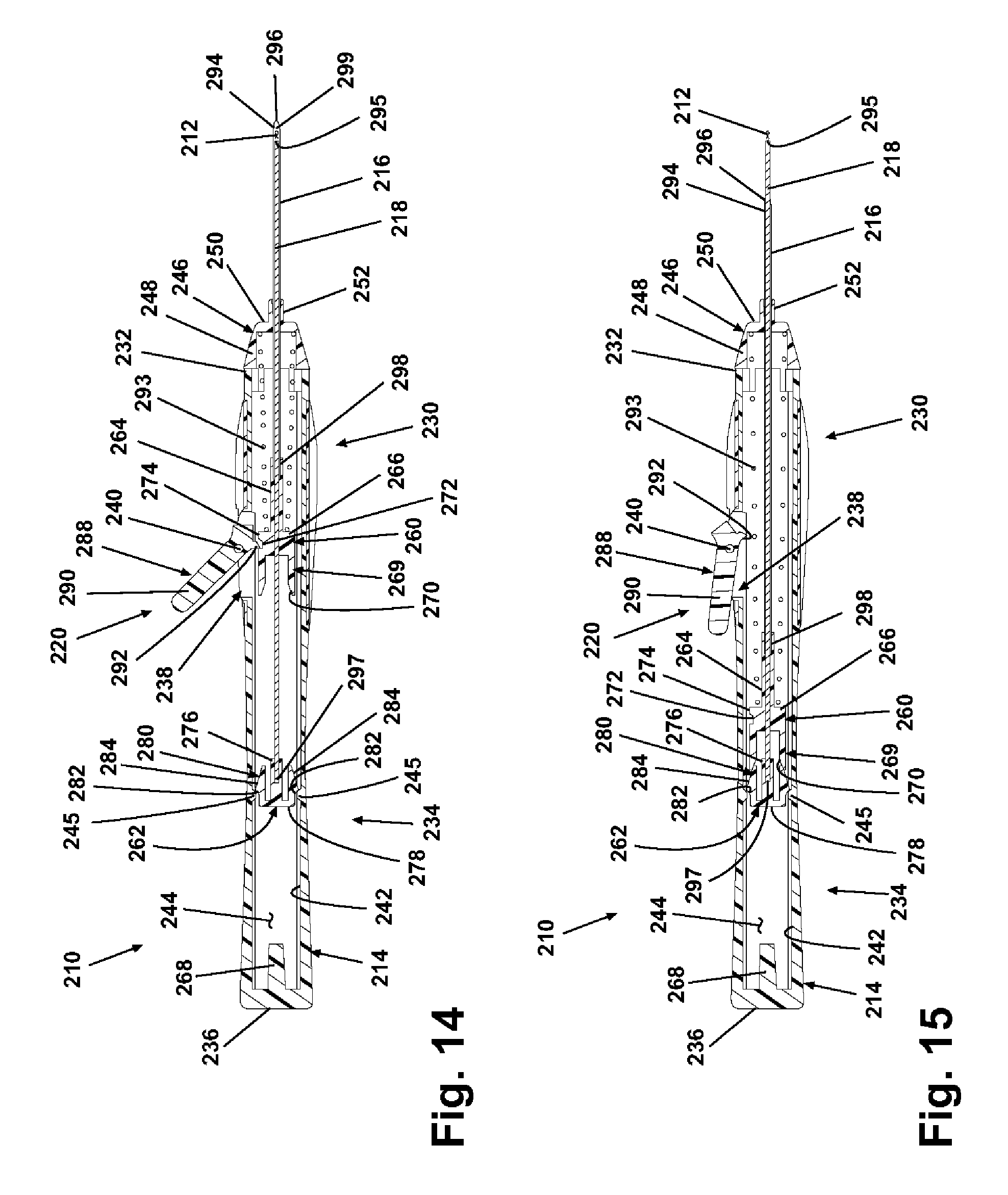
D00019

XML
uspto.report is an independent third-party trademark research tool that is not affiliated, endorsed, or sponsored by the United States Patent and Trademark Office (USPTO) or any other governmental organization. The information provided by uspto.report is based on publicly available data at the time of writing and is intended for informational purposes only.
While we strive to provide accurate and up-to-date information, we do not guarantee the accuracy, completeness, reliability, or suitability of the information displayed on this site. The use of this site is at your own risk. Any reliance you place on such information is therefore strictly at your own risk.
All official trademark data, including owner information, should be verified by visiting the official USPTO website at www.uspto.gov. This site is not intended to replace professional legal advice and should not be used as a substitute for consulting with a legal professional who is knowledgeable about trademark law.