Surgical tool systems and method
Crawford , et al. July 23, 2
U.S. patent number 10,357,184 [Application Number 14/062,707] was granted by the patent office on 2019-07-23 for surgical tool systems and method. This patent grant is currently assigned to Globus Medical, Inc.. The grantee listed for this patent is GLOBUS MEDICAL, INC. Invention is credited to Neil R. Crawford, Mitchell A Foster, Nicholas Theodore.


View All Diagrams
| United States Patent | 10,357,184 |
| Crawford , et al. | July 23, 2019 |
Surgical tool systems and method
Abstract
Embodiments of the invention provide a guided surgical tool assembly with a guide tube including a sensor, a surgical instrument including a detectable feature moveable within the guide tube, and the sensor capable of detecting the detectable feature when the surgical instrument is inserted in the guide tube. Some embodiments include a sensor pad, a guide stop coupled to the surgical instrument, a plunger mechanism including a compressible spring mechanism coupled to the guide tube, and a wiper capable of being sensed by the sensor pad. Some embodiments include a guided surgical tool assembly system comprising a tool sensor system including a processor and at least one data input/output interface. Some embodiments include a medical robot system with a guided surgical tool assembly and including a robot coupled to an effectuator element configured for controlled movement and positioning along one or more of an x-axis, a y-axis, and a z-axis.
| Inventors: | Crawford; Neil R. (Tempe, AZ), Theodore; Nicholas (Phoenix, AZ), Foster; Mitchell A (Phoenix, AZ) | ||||||||||
|---|---|---|---|---|---|---|---|---|---|---|---|
| Applicant: |
|
||||||||||
| Assignee: | Globus Medical, Inc. (Audubon,
PA) |
||||||||||
| Family ID: | 51530395 | ||||||||||
| Appl. No.: | 14/062,707 | ||||||||||
| Filed: | October 24, 2013 |
Prior Publication Data
| Document Identifier | Publication Date | |
|---|---|---|
| US 20140275955 A1 | Sep 18, 2014 | |
Related U.S. Patent Documents
| Application Number | Filing Date | Patent Number | Issue Date | ||
|---|---|---|---|---|---|
| 13924505 | Jun 21, 2013 | 9782229 | |||
| 61800527 | Mar 15, 2013 | ||||
| 61662702 | Jun 21, 2012 | ||||
| Current U.S. Class: | 1/1 |
| Current CPC Class: | A61B 90/98 (20160201); A61B 90/96 (20160201); A61B 34/30 (20160201); A61B 5/062 (20130101); A61B 5/061 (20130101); A61B 2090/3945 (20160201); A61B 2034/2051 (20160201); A61B 17/17 (20130101); A61B 2034/2055 (20160201); A61B 2017/00876 (20130101); A61B 90/11 (20160201); A61B 2090/3937 (20160201); A61B 5/064 (20130101); A61B 2090/0811 (20160201); A61B 2090/034 (20160201) |
| Current International Class: | A61B 5/00 (20060101); A61B 90/98 (20160101); A61B 34/30 (20160101); A61B 90/96 (20160101); A61B 5/06 (20060101); A61B 90/11 (20160101); A61B 34/20 (20160101); A61B 17/17 (20060101); A61B 17/00 (20060101); A61B 90/00 (20160101) |
References Cited [Referenced By]
U.S. Patent Documents
| 4150293 | April 1979 | Franke |
| 5246010 | September 1993 | Gazzara et al. |
| 5354314 | October 1994 | Hardy et al. |
| 5397323 | March 1995 | Taylor et al. |
| 5492527 | February 1996 | Glowa |
| 5598453 | January 1997 | Baba et al. |
| 5603318 | February 1997 | Heilbrun |
| 5772594 | June 1998 | Barrick |
| 5791908 | August 1998 | Gillio |
| 5820559 | October 1998 | Ng et al. |
| 5825982 | October 1998 | Wright et al. |
| 5887121 | March 1999 | Funda et al. |
| 5911449 | June 1999 | Daniele et al. |
| 5951475 | September 1999 | Gueziec et al. |
| 5987960 | November 1999 | Messner et al. |
| 6012216 | January 2000 | Esteves et al. |
| 6031888 | February 2000 | Ivan et al. |
| 6033415 | March 2000 | Mittelstadt et al. |
| 6080181 | June 2000 | Jensen et al. |
| 6106511 | August 2000 | Jensen |
| 6122541 | September 2000 | Cosman et al. |
| 6144875 | November 2000 | Schweikard et al. |
| 6157853 | December 2000 | Blume et al. |
| 6167145 | December 2000 | Foley et al. |
| 6167292 | December 2000 | Badano et al. |
| 6201984 | March 2001 | Funda et al. |
| 6203196 | March 2001 | Meyer et al. |
| 6205411 | March 2001 | DiGioia, III et al. |
| 6212419 | April 2001 | Blume et al. |
| 6231565 | May 2001 | Tovey et al. |
| 6236875 | May 2001 | Bucholz et al. |
| 6246900 | June 2001 | Cosman et al. |
| 6276471 | August 2001 | Kratzenberg et al. |
| 6301495 | October 2001 | Gueziec et al. |
| 6306126 | October 2001 | Montezuma |
| 6312435 | November 2001 | Wallace et al. |
| 6314311 | November 2001 | Williams et al. |
| 6320929 | November 2001 | Von Der Haar |
| 6322567 | November 2001 | Mittelstadt et al. |
| 6325808 | December 2001 | Bernard et al. |
| 6340363 | January 2002 | Bolger et al. |
| 6377011 | April 2002 | Ben-Ur |
| 6379302 | April 2002 | Kessman et al. |
| 6402762 | June 2002 | Hunter et al. |
| 6424885 | July 2002 | Niemeyer et al. |
| 6447503 | September 2002 | Wynne et al. |
| 6451027 | September 2002 | Cooper et al. |
| 6477400 | November 2002 | Barrick |
| 6484049 | November 2002 | Seeley et al. |
| 6487267 | November 2002 | Wolter |
| 6490467 | December 2002 | Bucholz et al. |
| 6490475 | December 2002 | Seeley et al. |
| 6499488 | December 2002 | Hunter et al. |
| 6501981 | December 2002 | Schweikard et al. |
| 6507751 | January 2003 | Blume et al. |
| 6535756 | March 2003 | Simon et al. |
| 6560354 | May 2003 | Maurer, Jr. et al. |
| 6565554 | May 2003 | Niemeyer |
| 6587750 | July 2003 | Gerbi et al. |
| 6614453 | September 2003 | Suri et al. |
| 6614871 | September 2003 | Kobiki et al. |
| 6619840 | September 2003 | Rasche et al. |
| 6636757 | October 2003 | Jascob et al. |
| 6645196 | November 2003 | Nixon et al. |
| 6666579 | December 2003 | Jensen |
| 6669635 | December 2003 | Kessman et al. |
| 6701173 | March 2004 | Nowinski et al. |
| 6757068 | June 2004 | Foxlin |
| 6782287 | August 2004 | Grzeszczuk et al. |
| 6783524 | August 2004 | Anderson et al. |
| 6786896 | September 2004 | Madhani et al. |
| 6788018 | September 2004 | Blumenkranz |
| 6804581 | October 2004 | Wang et al. |
| 6823207 | November 2004 | Jensen et al. |
| 6827351 | December 2004 | Graziani et al. |
| 6837892 | January 2005 | Shoham |
| 6839612 | January 2005 | Sanchez et al. |
| 6856826 | February 2005 | Seeley et al. |
| 6856827 | February 2005 | Seeley et al. |
| 6879880 | April 2005 | Nowlin et al. |
| 6892090 | May 2005 | Verard et al. |
| 6920347 | July 2005 | Simon et al. |
| 6922632 | July 2005 | Foxlin |
| 6968224 | November 2005 | Kessman et al. |
| 6978166 | December 2005 | Foley et al. |
| 6988009 | January 2006 | Grimm et al. |
| 6991627 | January 2006 | Madhani et al. |
| 6996487 | February 2006 | Jutras et al. |
| 6999852 | February 2006 | Green |
| 7007699 | March 2006 | Martinelli et al. |
| 7016457 | March 2006 | Senzig et al. |
| 7043961 | May 2006 | Pandey et al. |
| 7062006 | June 2006 | Pelc et al. |
| 7063705 | June 2006 | Young et al. |
| 7072707 | July 2006 | Galloway, Jr. et al. |
| 7083615 | August 2006 | Peterson et al. |
| 7097640 | August 2006 | Wang et al. |
| 7099428 | August 2006 | Clinthorne et al. |
| 7108421 | September 2006 | Gregerson et al. |
| 7130676 | October 2006 | Barrick |
| 7139418 | November 2006 | Abovitz et al. |
| 7139601 | November 2006 | Bucholz et al. |
| 7155316 | December 2006 | Sutherland et al. |
| 7164968 | January 2007 | Treat et al. |
| 7167738 | January 2007 | Schweikard et al. |
| 7169141 | January 2007 | Brock et al. |
| 7172627 | February 2007 | Fiere et al. |
| 7194120 | March 2007 | Wicker et al. |
| 7197107 | March 2007 | Arai et al. |
| 7231014 | June 2007 | Levy |
| 7231063 | June 2007 | Naimark et al. |
| 7239940 | July 2007 | Wang et al. |
| 7248914 | July 2007 | Hastings et al. |
| 7301648 | November 2007 | Foxlin |
| 7302288 | November 2007 | Schellenberg |
| 7313430 | December 2007 | Urquhart et al. |
| 7318805 | January 2008 | Schweikard et al. |
| 7318827 | January 2008 | Leitner et al. |
| 7319897 | January 2008 | Leitner et al. |
| 7324623 | January 2008 | Heuscher et al. |
| 7327865 | February 2008 | Fu et al. |
| 7331967 | February 2008 | Lee et al. |
| 7333642 | February 2008 | Green |
| 7339341 | March 2008 | Oleynikov et al. |
| 7366562 | April 2008 | Dukesherer et al. |
| 7379790 | May 2008 | Toth et al. |
| 7386365 | June 2008 | Nixon |
| 7422592 | September 2008 | Morley et al. |
| 7435216 | October 2008 | Kwon et al. |
| 7440793 | October 2008 | Chauhan et al. |
| 7460637 | December 2008 | Clinthorne et al. |
| 7466303 | December 2008 | Yi et al. |
| 7493153 | February 2009 | Ahmed et al. |
| 7505617 | March 2009 | Fu et al. |
| 7533892 | May 2009 | Schena et al. |
| 7542791 | June 2009 | Mire et al. |
| 7555331 | June 2009 | Viswanathan |
| 7567834 | July 2009 | Clayton et al. |
| 7594912 | September 2009 | Cooper et al. |
| 7606613 | October 2009 | Simon et al. |
| 7607440 | October 2009 | Coste-Maniere et al. |
| 7623902 | November 2009 | Pacheco |
| 7630752 | December 2009 | Viswanathan |
| 7630753 | December 2009 | Simon et al. |
| 7643862 | January 2010 | Schoenefeld |
| 7660623 | February 2010 | Hunter et al. |
| 7661881 | February 2010 | Gregerson et al. |
| 7683331 | March 2010 | Chang |
| 7683332 | March 2010 | Chang |
| 7689320 | March 2010 | Prisco et al. |
| 7691098 | April 2010 | Wallace et al. |
| 7702379 | April 2010 | Avinash et al. |
| 7702477 | April 2010 | Tuemmler et al. |
| 7711083 | May 2010 | Heigl et al. |
| 7711406 | May 2010 | Kuhn et al. |
| 7720523 | May 2010 | Omernick et al. |
| 7725253 | May 2010 | Foxlin |
| 7726171 | June 2010 | Langlotz et al. |
| 7742801 | June 2010 | Neubauer et al. |
| 7751865 | July 2010 | Jascob et al. |
| 7760849 | July 2010 | Zhang |
| 7762825 | July 2010 | Burbank et al. |
| 7763015 | July 2010 | Cooper et al. |
| 7787699 | August 2010 | Mahesh et al. |
| 7796728 | September 2010 | Bergfjord |
| 7813838 | October 2010 | Sommer |
| 7818044 | October 2010 | Dukesherer et al. |
| 7819859 | October 2010 | Prisco et al. |
| 7824401 | November 2010 | Manzo et al. |
| 7831294 | November 2010 | Viswanathan |
| 7834484 | November 2010 | Sartor |
| 7835557 | November 2010 | Kendrick et al. |
| 7835778 | November 2010 | Foley et al. |
| 7835784 | November 2010 | Mire et al. |
| 7840253 | November 2010 | Tremblay et al. |
| 7840256 | November 2010 | Lakin et al. |
| 7843158 | November 2010 | Prisco |
| 7844320 | November 2010 | Shahidi |
| 7853305 | December 2010 | Simon et al. |
| 7853313 | December 2010 | Thompson |
| 7865269 | January 2011 | Prisco et al. |
| D631966 | February 2011 | Perloff et al. |
| 7879045 | February 2011 | Gielen et al. |
| 7881767 | February 2011 | Strommer et al. |
| 7881770 | February 2011 | Melkent et al. |
| 7886743 | February 2011 | Cooper et al. |
| RE42194 | March 2011 | Foley et al. |
| RE42226 | March 2011 | Foley et al. |
| 7900524 | March 2011 | Calloway et al. |
| 7907166 | March 2011 | Lamprecht et al. |
| 7909122 | March 2011 | Schena et al. |
| 7925653 | April 2011 | Saptharishi |
| 7930065 | April 2011 | Larkin et al. |
| 7935130 | May 2011 | Willliams |
| 7940999 | May 2011 | Liao et al. |
| 7945012 | May 2011 | Ye et al. |
| 7945021 | May 2011 | Shapiro et al. |
| 7953470 | May 2011 | Vetter et al. |
| 7954397 | June 2011 | Choi et al. |
| 7971341 | July 2011 | Dukesherer et al. |
| 7974674 | July 2011 | Hauck et al. |
| 7974677 | July 2011 | Mire et al. |
| 7974681 | July 2011 | Wallace et al. |
| 7979157 | July 2011 | Anvari |
| 7983733 | July 2011 | Viswanathan |
| 7988215 | August 2011 | Seibold |
| 7996110 | August 2011 | Lipow et al. |
| 8004121 | August 2011 | Sartor |
| 8004229 | August 2011 | Nowlin et al. |
| 8010177 | August 2011 | Csavoy et al. |
| 8019045 | September 2011 | Kato |
| 8021310 | September 2011 | Sanborn et al. |
| 8035685 | October 2011 | Jensen |
| 8046054 | October 2011 | Kim et al. |
| 8046057 | October 2011 | Clarke |
| 8052688 | November 2011 | Wolf, II |
| 8054184 | November 2011 | Cline et al. |
| 8054752 | November 2011 | Druke et al. |
| 8057397 | November 2011 | Li et al. |
| 8057407 | November 2011 | Martinelli et al. |
| 8062288 | November 2011 | Cooper et al. |
| 8062375 | November 2011 | Glerum et al. |
| 8066524 | November 2011 | Burbank et al. |
| 8073335 | December 2011 | Labonville et al. |
| 8079950 | December 2011 | Stern et al. |
| 8086299 | December 2011 | Adler et al. |
| 8092370 | January 2012 | Roberts et al. |
| 8098914 | January 2012 | Liao et al. |
| 8100950 | January 2012 | St. Clair et al. |
| 8105320 | January 2012 | Manzo |
| 8108025 | January 2012 | Csavoy et al. |
| 8109877 | February 2012 | Moctezuma de la Barrera et al. |
| 8112292 | February 2012 | Simon |
| 8116430 | February 2012 | Shapiro et al. |
| 8120301 | February 2012 | Goldberg et al. |
| 8121249 | February 2012 | Wang et al. |
| 8123675 | February 2012 | Funda et al. |
| 8133229 | March 2012 | Bonutti |
| 8142420 | March 2012 | Schena |
| 8147494 | April 2012 | Leitner et al. |
| 8150494 | April 2012 | Simon et al. |
| 8150497 | April 2012 | Gielen et al. |
| 8150498 | April 2012 | Gielen et al. |
| 8165658 | April 2012 | Waynik et al. |
| 8170313 | May 2012 | Kendrick et al. |
| 8179073 | May 2012 | Farritor et al. |
| 8182476 | May 2012 | Julian et al. |
| 8184880 | May 2012 | Zhao et al. |
| 8202278 | June 2012 | Orban, III et al. |
| 8208708 | June 2012 | Homan et al. |
| 8208988 | June 2012 | Jensen |
| 8219177 | July 2012 | Smith et al. |
| 8219178 | July 2012 | Smith et al. |
| 8220468 | July 2012 | Cooper et al. |
| 8224024 | July 2012 | Foxlin et al. |
| 8224484 | July 2012 | Swarup et al. |
| 8225798 | July 2012 | Baldwin et al. |
| 8228368 | July 2012 | Zhao et al. |
| 8231610 | July 2012 | Jo et al. |
| 8263933 | July 2012 | Hartmann et al. |
| 8239001 | August 2012 | Verard et al. |
| 8241271 | August 2012 | Millman et al. |
| 8248413 | August 2012 | Gattani et al. |
| 8256319 | September 2012 | Cooper et al. |
| 8271069 | September 2012 | Jascob et al. |
| 8271130 | September 2012 | Hourtash |
| 8281670 | October 2012 | Larkin et al. |
| 8282653 | October 2012 | Nelson et al. |
| 8301226 | October 2012 | Csavoy et al. |
| 8311611 | November 2012 | Csavoy et al. |
| 8320991 | November 2012 | Jascob et al. |
| 8332012 | December 2012 | Kienzle, III |
| 8333755 | December 2012 | Cooper et al. |
| 8335552 | December 2012 | Stiles |
| 8335557 | December 2012 | Maschke |
| 8348931 | January 2013 | Cooper et al. |
| 8353963 | January 2013 | Glerum |
| 8358818 | January 2013 | Miga et al. |
| 8359730 | January 2013 | Burg et al. |
| 8374673 | February 2013 | Adcox et al. |
| 8374723 | February 2013 | Zhao et al. |
| 8379791 | February 2013 | Forthmann et al. |
| 8386019 | February 2013 | Camus et al. |
| 8392022 | March 2013 | Ortmaier et al. |
| 8394099 | March 2013 | Patwardhan |
| 8395342 | March 2013 | Prisco |
| 8398634 | March 2013 | Manzo et al. |
| 8400094 | March 2013 | Schena |
| 8414957 | April 2013 | Enzerink et al. |
| 8418073 | April 2013 | Mohr et al. |
| 8450694 | May 2013 | Baviera et al. |
| 8452447 | May 2013 | Nixon |
| RE44305 | June 2013 | Foley et al. |
| 8462911 | June 2013 | Vesel et al. |
| 8465476 | June 2013 | Rogers et al. |
| 8465771 | June 2013 | Wan et al. |
| 8467851 | June 2013 | Mire et al. |
| 8467852 | June 2013 | Csavoy et al. |
| 8469947 | June 2013 | Devengenzo et al. |
| RE44392 | July 2013 | Hynes |
| 8483434 | July 2013 | Buehner et al. |
| 8483800 | July 2013 | Jensen et al. |
| 8486532 | July 2013 | Enzerink et al. |
| 8489235 | July 2013 | Moll et al. |
| 8500722 | August 2013 | Cooper |
| 8500728 | August 2013 | Newton et al. |
| 8504201 | August 2013 | Moll et al. |
| 8506555 | August 2013 | Ruiz Morales |
| 8506556 | August 2013 | Schena |
| 8508173 | August 2013 | Goldberg et al. |
| 8512318 | August 2013 | Tovey et al. |
| 8515576 | August 2013 | Lipow et al. |
| 8518120 | August 2013 | Glerum et al. |
| 8521331 | August 2013 | Itkowitz |
| 8526688 | September 2013 | Groszmann et al. |
| 8526700 | September 2013 | Isaacs |
| 8527094 | September 2013 | Kumar et al. |
| 8528440 | September 2013 | Morley et al. |
| 8532741 | September 2013 | Heruth et al. |
| 8541970 | September 2013 | Nowlin et al. |
| 8548563 | October 2013 | Simon et al. |
| 8549732 | October 2013 | Burg et al. |
| 8551114 | October 2013 | Ramos de la Pena |
| 8551116 | October 2013 | Julian et al. |
| 8556807 | October 2013 | Scott et al. |
| 8556979 | October 2013 | Glerum et al. |
| 8560118 | October 2013 | Green et al. |
| 8561473 | October 2013 | Blumenkranz |
| 8562594 | October 2013 | Cooper et al. |
| 8571638 | October 2013 | Shoham |
| 8571710 | October 2013 | Coste-Maniere et al. |
| 8573465 | November 2013 | Shelton, IV |
| 8574303 | November 2013 | Sharkey et al. |
| 8585420 | November 2013 | Burbank et al. |
| 8594841 | November 2013 | Zhao et al. |
| 8597198 | December 2013 | Sanborn et al. |
| 8600478 | December 2013 | Verard et al. |
| 8603077 | December 2013 | Cooper et al. |
| 8611985 | December 2013 | Lavallee et al. |
| 8613230 | December 2013 | Blumenkranz et al. |
| 8621939 | January 2014 | Blumenkranz et al. |
| 8624537 | January 2014 | Nowlin et al. |
| 8630389 | January 2014 | Kato |
| 8634897 | January 2014 | Simon et al. |
| 8634957 | January 2014 | Toth et al. |
| 8638056 | January 2014 | Goldberg et al. |
| 8638057 | January 2014 | Goldberg et al. |
| 8639000 | January 2014 | Zhao et al. |
| 8641726 | February 2014 | Bonutti |
| 8644907 | February 2014 | Hartmann et al. |
| 8657809 | February 2014 | Schoepp |
| 8660635 | February 2014 | Simon et al. |
| 8666544 | March 2014 | Moll et al. |
| 8675939 | March 2014 | Moctezuma de la Barrera |
| 8678647 | March 2014 | Gregerson et al. |
| 8679125 | March 2014 | Smith et al. |
| 8679183 | March 2014 | Glerum et al. |
| 8682413 | March 2014 | Lloyd |
| 8684253 | April 2014 | Giordano et al. |
| 8685098 | April 2014 | Glerum et al. |
| 8693730 | April 2014 | Umasuthan et al. |
| 8694075 | April 2014 | Groszmann et al. |
| 8696458 | April 2014 | Foxlin et al. |
| 8700123 | April 2014 | Okamura et al. |
| 8706086 | April 2014 | Glerum |
| 8706185 | April 2014 | Foley et al. |
| 8706301 | April 2014 | Zhao et al. |
| 8717430 | May 2014 | Simon et al. |
| 8727618 | May 2014 | Maschke et al. |
| 8734432 | May 2014 | Tuma et al. |
| 8738115 | May 2014 | Amberg et al. |
| 8738181 | May 2014 | Greer et al. |
| 8740882 | June 2014 | Jun et al. |
| 8746252 | June 2014 | McGrogan et al. |
| 8749189 | June 2014 | Nowlin et al. |
| 8749190 | June 2014 | Nowlin et al. |
| 8761930 | June 2014 | Nixon |
| 8764448 | July 2014 | Yang et al. |
| 8771170 | July 2014 | Mesallum et al. |
| 8781186 | July 2014 | Clements et al. |
| 8781630 | July 2014 | Banks et al. |
| 8784385 | July 2014 | Boyden et al. |
| 8786241 | July 2014 | Nowlin et al. |
| 8787520 | July 2014 | Baba |
| 8792704 | July 2014 | Isaacs |
| 8798231 | August 2014 | Notohara et al. |
| 8800838 | August 2014 | Shelton, IV |
| 8808164 | August 2014 | Hoffman et al. |
| 8812077 | August 2014 | Dempsey |
| 8814793 | August 2014 | Brabrand |
| 8816628 | August 2014 | Nowlin et al. |
| 8818105 | August 2014 | Myronenko et al. |
| 8820605 | September 2014 | Shelton, IV |
| 8821511 | September 2014 | Von Jako et al. |
| 8823308 | September 2014 | Nowlin et al. |
| 8827996 | September 2014 | Scott et al. |
| 8828024 | September 2014 | Farritor et al. |
| 8830224 | September 2014 | Zhao et al. |
| 8834489 | September 2014 | Cooper et al. |
| 8834490 | September 2014 | Bonutti |
| 8838270 | September 2014 | Druke et al. |
| 8844789 | September 2014 | Shelton, IV et al. |
| 8855822 | October 2014 | Bartol et al. |
| 8858598 | October 2014 | Seifert et al. |
| 8860753 | October 2014 | Bhandarkar et al. |
| 8864751 | October 2014 | Prisco et al. |
| 8864798 | October 2014 | Weiman et al. |
| 8864833 | October 2014 | Glerum et al. |
| 8867703 | October 2014 | Shapiro et al. |
| 8870880 | October 2014 | Himmelberger et al. |
| 8876866 | November 2014 | Zappacosta et al. |
| 8880223 | November 2014 | Raj et al. |
| 8882803 | November 2014 | Iott et al. |
| 8883210 | November 2014 | Truncale et al. |
| 8888821 | November 2014 | Rezach et al. |
| 8888853 | November 2014 | Glerum et al. |
| 8888854 | November 2014 | Glerum et al. |
| 8894652 | November 2014 | Seifert et al. |
| 8894688 | November 2014 | Suh |
| 8894691 | November 2014 | Iott et al. |
| 8906069 | December 2014 | Hansell et al. |
| 8964934 | February 2015 | Ein-Gal |
| 8992580 | March 2015 | Bar et al. |
| 8996169 | March 2015 | Lightcap et al. |
| 9001963 | April 2015 | Sowards-Emmerd et al. |
| 9002076 | April 2015 | Khadem et al. |
| 9044190 | June 2015 | Rubner et al. |
| 9107683 | August 2015 | Hourtash et al. |
| 9125556 | September 2015 | Zehavi et al. |
| 9131986 | September 2015 | Greer et al. |
| 9215968 | December 2015 | Schostek et al. |
| 9308050 | April 2016 | Kostrzewski et al. |
| 9380984 | July 2016 | Li et al. |
| 9393039 | July 2016 | Lechner et al. |
| 9398886 | July 2016 | Gregerson et al. |
| 9398890 | July 2016 | Dong et al. |
| 9414859 | August 2016 | Ballard et al. |
| 9420975 | August 2016 | Gutfleisch et al. |
| 9492235 | November 2016 | Hourtash et al. |
| 9592096 | March 2017 | Maillet et al. |
| 9750465 | September 2017 | Engel et al. |
| 9757203 | September 2017 | Hourtash et al. |
| 9795354 | October 2017 | Menegaz et al. |
| 9814535 | November 2017 | Bar et al. |
| 9820783 | November 2017 | Donner et al. |
| 9833265 | November 2017 | Donner et al. |
| 9848922 | December 2017 | Tohmeh et al. |
| 9925011 | March 2018 | Gombert et al. |
| 9931025 | April 2018 | Graetzel et al. |
| 10034717 | July 2018 | Miller et al. |
| 2001/0036302 | November 2001 | Miller |
| 2002/0035321 | March 2002 | Bucholz et al. |
| 2002/0065481 | May 2002 | Cory |
| 2002/0167309 | November 2002 | Chaparala |
| 2003/0055049 | March 2003 | Brock |
| 2004/0068172 | April 2004 | Nowinski et al. |
| 2004/0076259 | April 2004 | Jensen et al. |
| 2004/0152972 | August 2004 | Hunter |
| 2005/0096502 | May 2005 | Khalili |
| 2005/0143651 | June 2005 | Verard et al. |
| 2005/0171558 | August 2005 | Abovitz et al. |
| 2006/0100610 | May 2006 | Wallace et al. |
| 2006/0142657 | June 2006 | Quaid |
| 2006/0173329 | August 2006 | Marquart et al. |
| 2006/0184396 | August 2006 | Dennis et al. |
| 2006/0241416 | October 2006 | Marquart et al. |
| 2006/0291612 | December 2006 | Nishide et al. |
| 2007/0015987 | January 2007 | Benlloch Baviera et al. |
| 2007/0021738 | January 2007 | Hasser et al. |
| 2007/0038059 | February 2007 | Sheffer et al. |
| 2007/0073133 | March 2007 | Schoenefeld |
| 2007/0078473 | April 2007 | Bodduluri |
| 2007/0156121 | July 2007 | Millman et al. |
| 2007/0156123 | July 2007 | Moll |
| 2007/0156157 | July 2007 | Nahum et al. |
| 2007/0167712 | July 2007 | Keglovich et al. |
| 2007/0197939 | August 2007 | Wallace |
| 2007/0233238 | October 2007 | Huynh et al. |
| 2008/0004523 | January 2008 | Jensen |
| 2008/0013809 | January 2008 | Zhu et al. |
| 2008/0027586 | January 2008 | Hem |
| 2008/0033283 | February 2008 | Dellaca et al. |
| 2008/0046122 | February 2008 | Manzo et al. |
| 2008/0082109 | April 2008 | Moll et al. |
| 2008/0108912 | May 2008 | Node-Langlois |
| 2008/0108991 | May 2008 | Von Jako |
| 2008/0109012 | May 2008 | Falco et al. |
| 2008/0144906 | June 2008 | Allred et al. |
| 2008/0161680 | July 2008 | Von Jako et al. |
| 2008/0161682 | July 2008 | Kendrick et al. |
| 2008/0177203 | July 2008 | von Jako |
| 2008/0214922 | September 2008 | Hartmann et al. |
| 2008/0215181 | September 2008 | Smith |
| 2008/0228068 | September 2008 | Viswanathan et al. |
| 2008/0228196 | September 2008 | Wang et al. |
| 2008/0235052 | September 2008 | Node-Langlois et al. |
| 2008/0269596 | October 2008 | Revie et al. |
| 2008/0287771 | November 2008 | Anderson |
| 2008/0287781 | November 2008 | Revie et al. |
| 2008/0294096 | November 2008 | Uber, III |
| 2008/0300477 | December 2008 | Lloyd et al. |
| 2008/0300478 | December 2008 | Zuhars et al. |
| 2008/0302950 | December 2008 | Park et al. |
| 2008/0306490 | December 2008 | Lakin et al. |
| 2008/0319311 | December 2008 | Hamadeh |
| 2009/0012509 | January 2009 | Csavoy et al. |
| 2009/0024142 | January 2009 | Ruiz Morales |
| 2009/0030428 | January 2009 | Omori et al. |
| 2009/0080737 | March 2009 | Battle et al. |
| 2009/0185655 | July 2009 | Koken et al. |
| 2009/0198121 | August 2009 | Hoheisel |
| 2009/0216113 | August 2009 | Meier et al. |
| 2009/0228019 | September 2009 | Gross et al. |
| 2009/0259123 | October 2009 | Navab et al. |
| 2009/0259230 | October 2009 | Khadem et al. |
| 2009/0264899 | October 2009 | Appenrodt et al. |
| 2009/0281417 | November 2009 | Hartmann et al. |
| 2010/0022874 | January 2010 | Wang et al. |
| 2010/0039506 | February 2010 | Sarvestani et al. |
| 2010/0114115 | May 2010 | Schlesinger |
| 2010/0125284 | May 2010 | Tanner |
| 2010/0125286 | May 2010 | Wang et al. |
| 2010/0130986 | May 2010 | Mailloux et al. |
| 2010/0228117 | September 2010 | Hartmann |
| 2010/0228265 | September 2010 | Prisco |
| 2010/0249571 | September 2010 | Jensen et al. |
| 2010/0274120 | October 2010 | Heuscher |
| 2010/0280363 | November 2010 | Skarda et al. |
| 2010/0331858 | December 2010 | Simaan et al. |
| 2011/0022229 | January 2011 | Jang et al. |
| 2011/0077504 | March 2011 | Fischer et al. |
| 2011/0098553 | April 2011 | Robbins et al. |
| 2011/0118542 | May 2011 | Cucin |
| 2011/0137152 | June 2011 | Li |
| 2011/0213384 | September 2011 | Jeong |
| 2011/0224684 | September 2011 | Larkin et al. |
| 2011/0224685 | September 2011 | Larkin et al. |
| 2011/0224686 | September 2011 | Larkin et al. |
| 2011/0224687 | September 2011 | Larkin et al. |
| 2011/0224688 | September 2011 | Larkin et al. |
| 2011/0224689 | September 2011 | Larkin et al. |
| 2011/0224825 | September 2011 | Larkin et al. |
| 2011/0230967 | September 2011 | O'Halloran et al. |
| 2011/0238080 | September 2011 | Ranjit et al. |
| 2011/0276058 | November 2011 | Choi et al. |
| 2011/0282189 | November 2011 | Graumann |
| 2011/0286573 | November 2011 | Schretter et al. |
| 2011/0295062 | December 2011 | Gratacos Solsona et al. |
| 2011/0295240 | December 2011 | Hamel |
| 2011/0295370 | December 2011 | Suh et al. |
| 2011/0306986 | December 2011 | Lee et al. |
| 2012/0035507 | February 2012 | George et al. |
| 2012/0046668 | February 2012 | Gantes |
| 2012/0051498 | March 2012 | Koishi |
| 2012/0053597 | March 2012 | Anvari et al. |
| 2012/0059248 | March 2012 | Holsing et al. |
| 2012/0071753 | March 2012 | Hunter et al. |
| 2012/0108954 | May 2012 | Schulhauser et al. |
| 2012/0136372 | May 2012 | Amat Girbau et al. |
| 2012/0143084 | June 2012 | Shoham |
| 2012/0184839 | July 2012 | Woerlein |
| 2012/0197182 | August 2012 | Millman et al. |
| 2012/0226145 | September 2012 | Chang et al. |
| 2012/0235909 | September 2012 | Birkenbach et al. |
| 2012/0245596 | September 2012 | Meenink |
| 2012/0253332 | October 2012 | Moll |
| 2012/0253360 | October 2012 | White et al. |
| 2012/0256092 | October 2012 | Zingerman |
| 2012/0294498 | November 2012 | Popovic |
| 2012/0296203 | November 2012 | Hartmann et al. |
| 2013/0006267 | January 2013 | Odermatt et al. |
| 2013/0016889 | January 2013 | Myronenko et al. |
| 2013/0030571 | January 2013 | Ruiz Morales et al. |
| 2013/0035583 | February 2013 | Park et al. |
| 2013/0060146 | March 2013 | Yang et al. |
| 2013/0060337 | March 2013 | Petersheim et al. |
| 2013/0094742 | April 2013 | Feilkas |
| 2013/0096574 | April 2013 | Kang et al. |
| 2013/0113791 | May 2013 | Isaacs et al. |
| 2013/0116706 | May 2013 | Lee et al. |
| 2013/0131695 | May 2013 | Scarfogliero et al. |
| 2013/0144307 | June 2013 | Jeong et al. |
| 2013/0158542 | June 2013 | Manzo et al. |
| 2013/0165937 | June 2013 | Patwardhan |
| 2013/0178867 | July 2013 | Farritor et al. |
| 2013/0178868 | July 2013 | Roh |
| 2013/0178870 | July 2013 | Schena |
| 2013/0204271 | August 2013 | Brisson et al. |
| 2013/0211419 | August 2013 | Jensen |
| 2013/0211420 | August 2013 | Jensen |
| 2013/0218142 | August 2013 | Tuma et al. |
| 2013/0223702 | August 2013 | Holsing et al. |
| 2013/0225942 | August 2013 | Holsing et al. |
| 2013/0225943 | August 2013 | Holsing et al. |
| 2013/0231556 | September 2013 | Holsing et al. |
| 2013/0237995 | September 2013 | Lee et al. |
| 2013/0245375 | September 2013 | DiMaio et al. |
| 2013/0261640 | October 2013 | Kim et al. |
| 2013/0272488 | October 2013 | Bailey et al. |
| 2013/0272489 | October 2013 | Dickman et al. |
| 2013/0274761 | October 2013 | Devengenzo et al. |
| 2013/0281821 | October 2013 | Liu et al. |
| 2013/0296884 | November 2013 | Taylor et al. |
| 2013/0303887 | November 2013 | Holsing et al. |
| 2013/0307955 | November 2013 | Deitz et al. |
| 2013/0317521 | November 2013 | Choi et al. |
| 2013/0325033 | December 2013 | Schena et al. |
| 2013/0325035 | December 2013 | Hauck et al. |
| 2013/0331686 | December 2013 | Freysinger et al. |
| 2013/0331858 | December 2013 | Devengenzo et al. |
| 2013/0331861 | December 2013 | Yoon |
| 2013/0342578 | December 2013 | Isaacs |
| 2013/0345717 | December 2013 | Markvicka et al. |
| 2013/0345718 | December 2013 | Crawford et al. |
| 2013/0345757 | December 2013 | Stad |
| 2014/0000098 | January 2014 | Dunning |
| 2014/0001235 | January 2014 | Shelton, IV |
| 2014/0012131 | January 2014 | Heruth et al. |
| 2014/0031664 | January 2014 | Kang et al. |
| 2014/0046128 | February 2014 | Lee et al. |
| 2014/0046132 | February 2014 | Hoeg et al. |
| 2014/0046340 | February 2014 | Wilson et al. |
| 2014/0049629 | February 2014 | Siewerdsen et al. |
| 2014/0058406 | February 2014 | Tsekos |
| 2014/0066944 | March 2014 | Taylor et al. |
| 2014/0073914 | March 2014 | Lavallee et al. |
| 2014/0080086 | March 2014 | Chen |
| 2014/0081128 | March 2014 | Verard et al. |
| 2014/0088612 | March 2014 | Bartol et al. |
| 2014/0094694 | April 2014 | Moctezuma de la Barrera |
| 2014/0094851 | April 2014 | Gordon |
| 2014/0096369 | April 2014 | Matsumoto et al. |
| 2014/0100587 | April 2014 | Farritor et al. |
| 2014/0121676 | May 2014 | Kostrzewski et al. |
| 2014/0128882 | May 2014 | Kwak et al. |
| 2014/0135796 | May 2014 | Simon et al. |
| 2014/0142591 | May 2014 | Alvarez et al. |
| 2014/0142592 | May 2014 | Moon et al. |
| 2014/0148692 | May 2014 | Hartmann et al. |
| 2014/0163581 | June 2014 | Devengenzo et al. |
| 2014/0171781 | June 2014 | Stiles |
| 2014/0171900 | June 2014 | Stiles |
| 2014/0171965 | June 2014 | Loh et al. |
| 2014/0180308 | June 2014 | von Grunberg |
| 2014/0180309 | June 2014 | Seeber et al. |
| 2014/0187915 | July 2014 | Yaroshenko et al. |
| 2014/0188132 | July 2014 | Kang |
| 2014/0194699 | July 2014 | Roh et al. |
| 2014/0130810 | August 2014 | Azizian et al. |
| 2014/0221819 | August 2014 | Sarment |
| 2014/0222023 | August 2014 | Kim et al. |
| 2014/0228631 | August 2014 | Kwak et al. |
| 2014/0234804 | August 2014 | Huang et al. |
| 2014/0257328 | September 2014 | Kim et al. |
| 2014/0257329 | September 2014 | Jang et al. |
| 2014/0257330 | September 2014 | Choi et al. |
| 2014/0275760 | September 2014 | Lee et al. |
| 2014/0275955 | September 2014 | Crawford et al. |
| 2014/0275985 | September 2014 | Walker et al. |
| 2014/0276931 | September 2014 | Parihar et al. |
| 2014/0276940 | September 2014 | Seo |
| 2014/0276944 | September 2014 | Farritor et al. |
| 2014/0288413 | September 2014 | Hwang et al. |
| 2014/0299648 | October 2014 | Shelton, IV et al. |
| 2014/0303434 | October 2014 | Farritor et al. |
| 2014/0303643 | October 2014 | Ha et al. |
| 2014/0305995 | October 2014 | Shelton, IV et al. |
| 2014/0309659 | October 2014 | Roh et al. |
| 2014/0316436 | October 2014 | Bar et al. |
| 2014/0323803 | October 2014 | Hoffman et al. |
| 2014/0324070 | October 2014 | Min et al. |
| 2014/0330288 | November 2014 | Date et al. |
| 2014/0364720 | December 2014 | Darrow et al. |
| 2014/0371577 | December 2014 | Maillet et al. |
| 2014/0379130 | December 2014 | Lee et al. |
| 2015/0039034 | February 2015 | Frankel et al. |
| 2015/0085970 | March 2015 | Bouhnik et al. |
| 2015/0146847 | May 2015 | Liu |
| 2015/0150524 | June 2015 | Yorkston et al. |
| 2015/0196261 | July 2015 | Funk |
| 2015/0213633 | July 2015 | Chang et al. |
| 2015/0335480 | November 2015 | Alvarez et al. |
| 2015/0342647 | December 2015 | Frankel et al. |
| 2016/0005194 | January 2016 | Schretter et al. |
| 2016/0166329 | June 2016 | Langan et al. |
| 2016/0235480 | August 2016 | Scholl et al. |
| 2016/0249990 | September 2016 | Glozman et al. |
| 2016/0302871 | October 2016 | Gregerson et al. |
| 2016/0320322 | November 2016 | Suzuki |
| 2016/0331335 | November 2016 | Gregerson et al. |
| 2017/0135770 | May 2017 | Scholl et al. |
| 2017/0143284 | May 2017 | Sehnert et al. |
| 2017/0143426 | May 2017 | Isaacs et al. |
| 2017/0156805 | June 2017 | Taylor |
| 2017/0156816 | June 2017 | Ibrahim |
| 2017/0202629 | July 2017 | Maillet et al. |
| 2017/0212723 | July 2017 | Atarot et al. |
| 2017/0215825 | August 2017 | Johnson et al. |
| 2017/0215826 | August 2017 | Johnson et al. |
| 2017/0215827 | August 2017 | Johnson et al. |
| 2017/0231710 | August 2017 | Scholl et al. |
| 2017/0258426 | September 2017 | Risher-Kelly et al. |
| 2017/0273748 | September 2017 | Hourtash et al. |
| 2017/0296277 | October 2017 | Hourtash et al. |
| 2017/0360493 | December 2017 | Zucher et al. |
| 0744633 | Nov 1996 | EP | |||
| 2286729 | Feb 2011 | EP | |||
| 898843 | Apr 1996 | JP | |||
| 8313304 | Nov 1996 | JP | |||
| 02071369 | Sep 2002 | WO | |||
| WO 2010075292 | Jul 2010 | WO | |||
| 2012018816 | Feb 2012 | WO | |||
Other References
|
US 8,231,638 B2, 07/2012, Swarup et al. (withdrawn) cited by applicant . Edward Rarnsden, Hall Effect Sensors; Theory and Application (2nd Edition), pp. 107-130, http://store.elsevier.com/Hall-Effect-Sensors/Edward-Ramsden/isbn-9780080- 523743/. Feb. 28, 2006. cited by applicant . Shuanghui, Hao et al., Study on a novel absolute magnetic encoder, Robotice and Biomemetics, 2009, Robio, 2009. IEEE, International Conference on IEEE. pp. 1773-1776, Feb. 22, 2009. cited by applicant . Eric M. Yeatmann et al., "Use of Scanned Detection in Optical Position Encoders", IEEE, Transactions of Instrumentation and Measurement. vol. 53, No. 1, pp. 37-44. http://www3.imperial.ac.uk/pls/portallive/docs/1/375913.PDF. Feb. 28, 2004. cited by applicant . Nevro Corp. v. Boston Scientific Corp. et al, U.S. Dist. Court ND California, Complaint for Patent Infringement and Declaratory Judgement, Case No. 16-cv-6830, 10 pages. cited by applicant . State of the Art Search for Imaging Devices Used in Conjunction With Surgical Navigation Software for Registering Image Data, performed by Shane Davis of Optimized Intellectual Property Solutions, Nov. 5, 2014, 2 pages. cited by applicant . Search Report for: Automatic Planning of Surgical Screw Position During a Robot Assisted Surgical Procedure by John Johnson, dated Jan. 18, 2018 (GM801), 2 pages. cited by applicant . Search Report for: Breathing Meter for Robotic Assisted Surgery by John Johnson, dated Jan. 22, 2018 (GM802), 3 pages. cited by applicant . Search Report for: Instrument Verification Improvement by John Johnson, dated May 22, 2018 (GM813), 2 pages. cited by applicant . Search Report for: Hammerhead Probe by John Johnson, dated Jul. 3, 2018 (GM816), 2 pages. cited by applicant . Search Report for: Navigation of a Bent Rod by John Johnson, dated Jul. 6, 2018 (GM817), 2 pages. cited by applicant . Search Report for: Large Field of View Cone Beam CT by John Johnson, dated Jul. 12, 2018 (GM818), 2 pages. cited by applicant . Search Report for: Robot Collision Detection by John Johnson, dated Aug. 3, 2018 (GM819), 4 pages. cited by applicant . Search Report for: Implant Trajectory and Tool Planning via Navigated Instrument by John Johnson, dated Aug. 9, 2018 (GM820), 3 pages. cited by applicant . Search Report for: Improved Low-Contrast CBCT Imaging by John Johnson, dated Aug. 6, 2018 (GM821), 3 pages. cited by applicant . Allowed Claims, showing Amendments to the claims for U.S. Patent Application Publication No. 2009/0185655, 7 pages. cited by applicant . Allowed Claims, showing Amendments to the claims for U.S. Patent Application Publication No. 2016/0005194, 4 pages. cited by applicant . Patent Search for CBCT-fluoroscopy-radiography, Mar. 2, 2018. cited by applicant. |
Primary Examiner: Chen; Tse W
Assistant Examiner: Hoffman; Joanne M
Parent Case Text
RELATED APPLICATIONS
This application claims priority under 35 U.S.C. .sctn. 120 to U.S. patent application Ser. No. 13/924,505 filed on Jun. 21, 2013, which claims the priority 35 U.S.C. .sctn. 119 to U.S. Provisional Patent Application No. 61/662,702 filed on Jun. 21, 2012 and U.S. Provisional Patent Application No. 61/800,527 filed on Mar. 15, 2013, each of which are incorporated herein by reference in their entirety.
Claims
The invention claimed is:
1. A surgical robot system comprising: a display; a housing; an arm; and a guided surgical tool assembly coupled to the arm, the guided surgical tool assembly comprising: a rigid guide tube disposed in the guided surgical tool assembly, wherein the rigid guide tube is a single hollow structure including at least one sensor disposed inside the single hollow structure, wherein the rigid guide tube is configured to removably receive one of a plurality of surgical instruments associated with spinal surgery; a surgical instrument configured to be received within the single hollow structure containing the at least one sensor, the surgical instrument including at least one detectable feature extending longitudinally along the surgical instrument; and wherein the at least one sensor is configured and arranged to couple with the at least one detectable feature when the surgical instrument is inside the single hollow structure to determine a position of the surgical instrument within the guide tube, wherein the surgical robot system is configured to calibrate a targeting fixture to a medical image received by the surgical robot system in order track movement of the surgical instrument, receive data indicative of an intended trajectory associated with the medical image, and move the arm and guide surgical tool in accordance with the intended trajectory wherein the detectable feature includes at least one longitudinal magnetic strip and at least one radial magnetic strip, wherein the at least one longitudinal magnetic strip extends the entire length of the guide tube and the radial magnetic strip is positioned proximal to a first opening and extending the entire circumference of the guide tube.
2. The surgical robot system of claim 1, wherein the detectable feature comprises a magnetically detectable feature for generating a magnetic flux field; and wherein the sensor is a position sensor for detecting the magnetic flux field.
3. The surgical robot system of claim 1, wherein the position sensor is a magnetic flux field sensor selected from a group consisting of a ferrite-based magnetic material, a rare-earth based magnetic material, an aluminum-nickel-cobalt based magnetic material, and mixtures thereof.
4. The surgical robot system of claim 2, wherein the position sensor is configured and arranged to detect insertion into and movement of the surgical instrument in the guide tube by sensing the magnetically detectable feature.
5. The surgical robot system of claim 1, wherein the guide tube includes at least two position sensors.
6. The surgical robot system of claim 5, wherein the at least two position sensors are configured and arranged to sense a magnetic field flux from the longitudinal magnetic strip or the radial magnetic field strip or both.
7. The surgical robot system of claim 6, wherein a longitudinal position of the surgical instrument in the guide tube can be at least partially determined using a measurement of a magnetic field flux from the longitudinal magnetic strip.
8. The surgical robot system of claim 6, wherein a radial position of the surgical instrument in the guide tube can be at least partially determined using a measurement of a magnetic field flux from the radial magnetic strip.
9. The surgical robot system assembly of claim 1, wherein the detectable feature comprises an optically detectable feature; and wherein the at least one sensor comprises at least one optical sensor.
10. The surgical robot system assembly of claim 9, wherein the optically detectable feature comprises a high contrast marking distributed along at least a partial longitudinal length of the guided surgical tool assembly.
11. The surgical robot system of claim 10, wherein the at least one optical sensor comprises a light sensitive detector selected from a group consisting of a photodiode, a phototransistor, a fiber-optic sensor, a photo-multiplier, a CCD, a camera, or a combination thereof.
12. The surgical robot system of claim 10, wherein a longitudinal position of the surgical instrument in the guide tube can be at least partially determined by optically sensing light from the high contrast marking using the at least one optical sensor.
13. The surgical robot system of claim 9, wherein the optically detectable feature comprises a graduated coating distributed along at least a length of the guided surgical tool assembly.
14. The surgical robot system of claim 13, wherein the graduated coating comprises a graduated reflective coating.
15. The surgical robot system of claim 13, wherein the graduated coating comprises a graduated color coating.
16. The surgical robot system of claim 13, wherein a longitudinal position of the surgical instrument in the guide tube can be at least partially determined by optically sensing light from the graduated coating using the at least one optical sensor.
17. The surgical robot system of claim 1, wherein the guide tube comprises a distal guide tube end and a proximal guide tube end; and the surgical instrument includes a distal end and a proximal end; and wherein the sensor comprises at least one sensor pad; and wherein the guided surgical tool assembly further comprises: a guide stop coupled to the proximal end of the surgical instrument; and a plunger mechanism including a compressible spring mechanism coupled to the distal end of the guide tube and a wiper configured and arranged to be sensed by the at least one sensor pad.
18. The surgical robot system of claim 17, wherein longitudinal movement of the surgical instrument within the guide tube where the guide stop moves toward the proximal end of the guide tube can at least partially compress the spring and move the wiper with respect to the at least one sensor pad.
19. The surgical robot system of claim 17, wherein longitudinal movement of the surgical instrument within the guide tube where the guide stop moves away from the proximal end of the guide tube can at least partially decompress the spring and move the wiper with respect to the at least one sensor pad.
20. A surgical robot system comprising: a surgical robot having a display, a housing, and an arm; a guide surgical tool assembly coupled to the arm of the surgical robot, the guide surgical tool assembly comprising: a tool sensor system including at least one processor and at least one data input/output interface, the data input interface including at least one sensor; a rigid guide tube disposed in the guide surgical tool assembly, wherein the rigid guide tube is a single hollow structure and the at least one sensor is disposed inside the single hollow structure, wherein the rigid guide tube is configured to removably receive one of a plurality of surgical instruments associated with spinal surgery; and a surgical instrument configured to be received within the single hollow structure containing the at least one sensor and moveable within the guide tube, the surgical instrument including at least one detectable feature extending longitudinally along the surgical instrument; wherein the at least one sensor is configured and arranged to couple with the at least one detectable feature when the surgical instrument is inside the single hollow structure to determine a position of the surgical instrument within the guide tube, wherein the surgical robot system is configured to calibrate a targeting fixture to a medical image received by the surgical robot system in order to track movement of the surgical instrument relative to the medical image, receive data indicative of an intended trajectory associated with the medical image, and move the arm and guide surgical tool in accordance with the intended trajectory wherein the detectable feature includes at least one longitudinal magnetic strip and at least one radial magnetic strip, wherein the at least one longitudinal magnetic strip extends the entire length of the guide tube and the radial magnetic strip is positioned proximal to a first opening and extending the entire circumference of the guide tube.
21. A surgical robot system of claim 20, wherein the guide tube comprises a distal guide tube end and a proximal guide tube end; and the surgical instrument includes a distal end and a proximal end; and wherein the sensor comprises at least one sensor pad; and wherein the guided surgical tool assembly further comprises: a guide stop coupled to the proximal end of the surgical instrument; and a plunger mechanism including a compressible spring mechanism coupled to the distal end of the guide tube and a wiper configured and arranged to be sensed by the at least one sensor pad; and wherein the at least one processor is configured and arranged to detect the at least one surgical instrument when at least partially inserted or moved in the guide tube.
22. The surgical robot system of claim 20, wherein the detectable feature comprises a magnetically detectable feature configured to generate a magnetic flux field; and wherein the sensor is a position sensor for detecting the magnetic flux field; and wherein the position sensor is configured and arranged to detect insertion into and movement of the surgical instrument in the guide tube by sensing the magnetically detectable feature.
23. The surgical robot system of claim 20, wherein the detectable feature comprises an optically detectable feature; and wherein the at least one sensor comprises at least one optical sensor; and wherein the optically detectable feature comprises a high contrast marking distributed along length of the guided surgical tool assembly.
24. The surgical robot system of claim 20, wherein the detectable feature comprises an optically detectable feature; and wherein the at least one sensor comprises at least one optical sensor; and wherein the optically detectable feature comprises a graduated coating distributed along a length of the guided surgical tool assembly.
25. A surgical robot system of claim 20, wherein the surgical instrument includes at least one tracking sensor.
26. A medical robot system, comprising: a robot comprising a display, a housing, and an arm, the robot configured for controlled movement and positioning; an effectuator element coupled to the arm; a motor assembly coupled to the robot, the motor assembly being configured to move the effectuator element along one or more of an x-axis, a y-axis, and a z-axis such that movement of the effectuator element along one of the x-, y-, or z-axes occurs independently of movement of the effectuator element along the other axes of the x-, y-, and z-axes, wherein the x-axis is perpendicular to the y- and z-axes, the y-axis is perpendicular to the x- and z-axes, and the z-axis is perpendicular to the x- and y axes; a tool sensor system including at least one processor and at least one data input/output interface, the data input interface including at least one sensor; a guide tube disposed in the effectuator element, wherein the guide tube is a single hollow structure including the at least one sensor disposed inside the single hollow structure, wherein the guide tube is configured to removably receive one of a plurality of surgical instruments associated with spinal surgery; and a surgical instrument configured to be received within the single hollow structure containing the at least one sensor and moveable within the guide tube, the surgical instrument including at least one detectable feature extending longitudinally along the surgical instrument; wherein the at least one sensor is configured and arranged to couple with the at least one detectable feature when the surgical instrument is inside the single hollow structure to determine a position of the surgical instrument within the guide tube; and wherein the at least one processor is configured and arranged to detect when the surgical instrument is inside the single hollow structure, wherein the guide tube is rigid and the surgical instrument includes a guide stop that contacts a proximal end of the rigid guide tube to prevent the surgical instrument from extending further, wherein the surgical robot system is configured to calibrate a targeting fixture to a medical image received by the surgical robot system in order to track movement of the surgical instrument relative to the medical image, receive data indicative of an intended trajectory associated with the medical image, and move the arm and guide surgical tool in accordance with the intended trajectory wherein the detectable feature includes at least one longitudinal magnetic strip and at least one radial magnetic strip, wherein the at least one longitudinal magnetic strip extends the entire length of the guide tube and the radial magnetic strip is positioned proximal to a first opening and extending the entire circumference of the guide tube.
27. A medical robot system of claim 26, wherein the surgical instrument includes at least one tracking sensor.
Description
BACKGROUND
Various medical procedures require the accurate localization of a three-dimensional position of a surgical instrument within the body in order to effect optimized treatment. For example, some surgical procedures to fuse vertebrae require that a surgeon drill multiple holes into the bone structure at specific locations. To achieve high levels of mechanical integrity in the fusing system, and to balance the forces created in the bone structure, it is necessary that the holes are drilled at the correct location. Vertebrae, like most bone structures, have complex shapes including non-planar curved surfaces making accurate and perpendicular drilling difficult. Conventionally, a surgeon manually holds and positions a drill guide tube by using a guidance system to overlay the drill tube's position onto a three dimensional image of the bone structure. This manual process is both tedious and time consuming. The success of the surgery is largely dependent upon the dexterity of the surgeon who performs it.
Limited robotic assistance for surgical procedures is currently available. For example, the da Vinci.RTM. medical robot system (da Vinci.RTM. is a registered trademark of Intuitive Surgical) is a robot used in certain surgical applications. In the da Vinci.RTM. system, the user controls manipulators that control a robotic actuator. The system converts the surgeon's gross movements into micro-movements of the robotic actuator. Although the da Vinci.RTM. system eliminates hand tremor and provides the user with the ability to work through a small opening, like many of the robots commercially available today, it is expensive, obtrusive, and the setup is cumbersome. Further, for procedures such as thoracolumbar pedicle screw insertion, these conventional methods are known to be error-prone and tedious.
One of the characteristics of many of the current robots used in surgical applications which make them error prone is that autonomous movement and precise placement of a surgical instrument can be hindered by lack of mechanical feedback and/or loss of visual placement once the instrument is submerged within a portion of a patient.
SUMMARY
Some embodiments of the invention provide a guided surgical tool assembly comprising a guide tube including at least one sensor and a surgical instrument including at least one detectable feature moveable within the guide tube. In some embodiments, the at least one sensor is configured and arranged to detect the at least one detectable feature when the surgical instrument is at least partially inserted in the guide tube.
Some embodiments include a detectable feature comprising a magnetically detectable feature capable of generating a magnetic flux field, and in some embodiments, the sensor is a position sensor capable of detecting the magnetic flux field. Some embodiments also include a position sensor configured and arranged to detect insertion into and movement of the surgical instrument in the guide tube by sensing the magnetically detectable feature. In some embodiments, the position sensor is a magnetic flux field sensor selected from a group consisting of a ferrite-based magnetic material, a rare-earth based magnetic material, an aluminum-nickel-cobalt based magnetic material, and mixtures thereof.
In some embodiments, the detectable feature includes at least one longitudinal magnetic strip and at least one radial magnetic strip. Further, in some embodiments, the guide tube includes at least three position sensors, and in some embodiments, the at least three position sensors are configured and arranged to sense a magnetic field flux from the longitudinal magnetic strip or the radial magnetic field strip or both.
In some embodiments, the longitudinal position of the surgical instrument in the guide tube can be at least partially determined using a measurement of a magnetic field flux from the longitudinal magnetic strip. In other embodiments, a radial position of the surgical instrument in the guide tube can be at least partially determined using a measurement of a magnetic field flux from the radial magnetic strip.
Some embodiments include a detectable feature comprising an optically detectable feature, and at least one sensor comprising at least one optical sensor. In some embodiments, the optically detectable feature comprises a contrasting or high contrast marking distributed along at least a partial longitudinal length of the guided surgical tool assembly.
Some embodiments include at least one optical sensor comprising a light sensitive detector selected from a group consisting of a photodiode, a phototransistor, a fiber-optic sensor, a photo-multiplier, a CCD, a camera, or a combination thereof.
In some embodiments, the longitudinal position of the surgical instrument in the guide tube can be at least partially determined by optically sensing light from the high contrast marking using the at least one optical sensor.
Some embodiments include an optically detectable feature comprising a graduated coating distributed along at least a partial longitudinal length of the guided surgical tool assembly. In some embodiments, the graduated coating comprises a graduated reflective coating. In other embodiments, the graduated coating comprises a graduated color coating.
In some embodiments, the longitudinal position of the surgical instrument in the guide tube can be at least partially determined by optically sensing light from the graduated coating using the at least one optical sensor.
Some embodiments include a guided surgical tool assembly wherein the guide tube comprises a distal guide tube end and a proximal guide tube end, and the surgical instrument includes a distal end and a proximal end. In some embodiments, the sensor comprises at least one sensor pad. The guided surgical tool assembly can further comprise a guide stop coupled to the proximal end of the surgical instrument, and a plunger mechanism. The plunger mechanism can include a compressible spring mechanism coupled to the distal end of the guide tube and a wiper configured and arranged to be sensed by the at least one sensor pad.
In some embodiments of the guided surgical tool assembly, longitudinal movement of the surgical instrument within the guide tube (where the guide stop moves toward the proximal end of the guide tube) can at least partially compress the spring and move the wiper with respect to the at least one sensor pad. In other embodiments, longitudinal movement of the surgical instrument within the guide tube where the guide stop moves away from the proximal end of the guide tube can at least partially decompress the spring and move the wiper with respect to the at least one sensor pad.
Some embodiments include a guided surgical tool assembly system comprising a tool sensor system including at least one processor and at least one data input/output interface. In some embodiments, the data input interface including at least one sensor, a guide tube including the at least one sensor, and a surgical instrument moveable within the guide tube. In some embodiments, the surgical instrument includes at least one detectable feature, and the at least one sensor is configured and arranged to detect the at least one detectable feature.
In some embodiments, the guided surgical tool assembly system includes a guide tube comprising a distal guide tube end and a proximal guide tube end, and the surgical instrument includes a distal end and a proximal end. In some embodiments, the sensor comprises at least one sensor pad, and the guided surgical tool assembly further comprises a guide stop coupled to the proximal end of the surgical instrument, the plunger mechanism can include a compressible spring mechanism coupled to the distal end of the guide tube and a wiper configured and arranged to be sensed by the at least one sensor pad. The at least one processor can be configured and arranged to detect the at least one surgical instrument when the instrument at least partially inserted or moved in the guide tube.
In some embodiments of the guided surgical tool assembly system, the detectable feature comprises a magnetically detectable feature capable of generating a magnetic flux field. The sensor can be a position sensor capable of detecting the magnetic flux field, and be configured and arranged to detect insertion into and movement of the surgical instrument in the guide tube by sensing the magnetically detectable feature.
Some embodiments include a guided surgical tool assembly system in which the detectable feature comprises an optically detectable feature, and the at least one sensor comprises at least one optical sensor. The optically detectable feature can comprise a contrasting or high contrast marking distributed along at least a partial longitudinal length of the guided surgical tool assembly. In some embodiments, the detectable feature comprises an optically detectable feature, and the at least one sensor comprises at least one optical sensor. The optically detectable feature can comprise a graduated coating distributed along at least a partial longitudinal length of the guided surgical tool assembly.
Some embodiments include a medical robot system comprising a robot coupled to an effectuator element configured for controlled movement and positioning, and a motor assembly coupled to the robot. The motor assembly can be configured to move the effectuator element along one or more of an x-axis, a y-axis, and a z-axis such that movement of the effectuator element along one of the x-, y-, or z-axes occurs independently of movement of the effectuator element along the other axes of the x-, y-, and z-axes, wherein the x-axis is substantially perpendicular to the y- and z-axes, the y-axis is substantially perpendicular to the x- and z-axes, and the z-axis is substantially perpendicular to the x- and y axes.
In some embodiments, the medical robot system also comprises a tool sensor system including at least one processor and at least one data input/output interface, the data input interface including at least one sensor, and a guide tube including the at least one sensor. In some embodiments, the surgical instrument is moveable within the guide tube, and the surgical instrument includes at least one detectable feature. Further, in some embodiments, the at least one sensor is configured and arranged to detect the at least one detectable feature, and the at least one processor is configured and arranged to detect when the surgical instrument is at least partially inserted in the guide tube. In some embodiments, the detectable feature can include one or more of instrument length, type, torque ranges, depth of treatment parameters and other instrument parameters. Some embodiments include a tracking marker coupled to the surgical instrument.
DESCRIPTION OF THE DRAWINGS
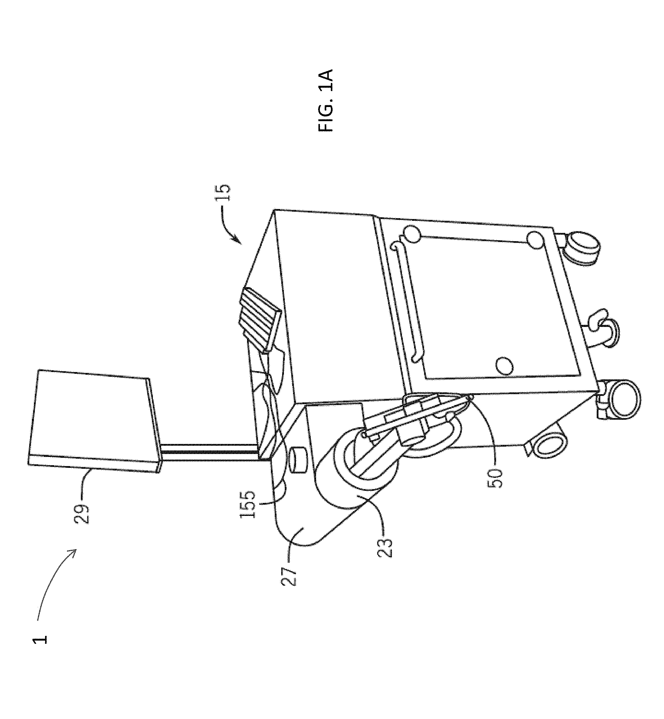
FIGS. 1A-1B illustrate a surgical robot in accordance with one embodiment of the invention.
FIG. 1C illustrates a portion of a surgical robot with control of the translation and orientation of the end-effectuator in accordance with another embodiment of the invention.
FIG. 1D illustrates a partial view of a surgical robot having a plurality of optical markers mounted for calibration and tracking movement in accordance with one embodiment of the invention.
FIG. 2 illustrates a surgical robot operating on a patient in accordance with one embodiment of the invention.
FIGS. 3A-3B each illustrates a tool assembly including a surgical instrument having a guide stop mechanism in accordance with one embodiment of the invention.
FIGS. 4A-4D each depict a tool assembly including a surgical instrument having a guide stop mechanism in accordance with one embodiment of the invention.
FIGS. 5A-5C each illustrates tools for manually adjusting a drill stop with reference to drill bit markings in accordance with one embodiment of the invention.
FIGS. 5D-5F each illustrates tools for locking and holding a drill bit in a set position in accordance with one embodiment of the invention.
FIGS. 5G-5H each illustrates methods of use of the tools as depicted in FIGS. 5A-5F with a robot end effectuator coupled to a robot system.
FIG. 6A illustrates a tool assembly including a surgical instrument having a sensor enabled guide stop mechanism in accordance with one embodiment of the invention.
FIG. 6B illustrates a tool assembly system architecture in accordance with one embodiment of the invention.
FIG. 7A illustrates a tool comprising a surgical instrument having a guide stop mechanism in accordance with another embodiment of the invention.
FIG. 7B is a modified guide tube for use with the tool assembly shown in FIG. 7C in accordance with one embodiment of the invention.
FIG. 7C shows the tool shown in FIG. 7A inserted within the modified guide tube shown in FIG. 7B to form a tool assembly in accordance with one embodiment of the invention.
FIG. 8A illustrates a tool assembly including a surgical instrument having a guide stop mechanism in accordance with another embodiment of the invention.
FIG. 8B illustrates a tool assembly including a surgical instrument having a guide stop inserted within a modified guide tube in accordance with another embodiment of the invention.
FIG. 9 illustrates a tool assembly including a surgical instrument having a guide stop inserted within a modified guide tube in accordance with another embodiment of the invention.
FIG. 10 illustrates a tool assembly including a surgical instrument having at least one tracking marker in accordance with a further embodiment of the invention.
DETAILED DESCRIPTION
Before any embodiments of the invention are explained in detail, it is to be understood that the invention is not limited in its application to the details of construction and the arrangement of components set forth in the following description or illustrated in the following drawings. The invention is capable of other embodiments and of being practiced or of being carried out in various ways. Also, it is to be understood that the phraseology and terminology used herein is for the purpose of description and should not be regarded as limiting. The use of "including," "comprising," or "having" and variations thereof herein is meant to encompass the items listed thereafter and equivalents thereof as well as additional items. Unless specified or limited otherwise, the terms "mounted," "connected," "supported," and "coupled" and variations thereof are used broadly and encompass both direct and indirect mountings, connections, supports, and couplings. Further, "connected" and "coupled" are not restricted to physical or mechanical connections or couplings.
The following discussion is presented to enable a person skilled in the art to make and use embodiments of the invention. Various modifications to the illustrated embodiments will be readily apparent to those skilled in the art, and the generic principles herein can be applied to other embodiments and applications without departing from embodiments of the invention. Thus, embodiments of the invention are not intended to be limited to embodiments shown, but are to be accorded the widest scope consistent with the principles and features disclosed herein. The following detailed description is to be read with reference to the figures, in which like elements in different figures have like reference numerals. The figures, which are not necessarily to scale, depict selected embodiments and are not intended to limit the scope of embodiments of the invention. Skilled artisans will recognize the examples provided herein have many useful alternatives and fall within the scope of embodiments of the invention.
FIGS. 1A-1B illustrate a surgical robot system 1 in accordance with one embodiment of the invention, and FIG. 1C illustrates a portion of a surgical robot system 1 with control of the translation and orientation of the end-effectuator in accordance with another embodiment of the invention. Referring now to FIGS. 1A-1B, some embodiments include a surgical robot system 1. As shown, in some embodiments, the surgical robot 15 can comprise a display 29 and a housing 27. In some embodiments, the display 29 can be attached to the surgical robot 15. In other embodiments, a display 29 can be detached from surgical robot 15, either within a surgical room with the surgical robot 15, or in a remote location. In some embodiments, the housing 27 can comprise a robot arm 23, and an end-effectuator 30 coupled to the robot arm 23 controlled by at least one conventional motor. In some embodiments, the end-effectuator 30 can comprise an instrument used to perform surgery on a patient 18 (such as for example the surgical instrument 35 depicted in FIGS. 3A-3B, 4A-4D, 6A, 7A, 7C, 8A-8B, 9 and 10). In other embodiments, the end-effectuator 30 can be coupled to the surgical instrument 35. As used herein, the term "end-effectuator" is used interchangeably with the term "effectuator element." In some embodiments, the end-effectuator 30 can comprise any known structure for effecting the movement of the surgical instrument 35 in a desired manner.
FIG. 1C illustrates a portion of a surgical robot 15 with control of the translation and orientation of the end-effectuator in accordance with another embodiment of the invention. As shown, some embodiments include a surgical robot system 1 capable of the utilization of a robot 15 with the ability of moving the end-effectuator 30 along x-, y-, and z-axes (see 66, 68, 70 in FIG. 1C). In this embodiment, the x-axis 66 can be orthogonal to the y-axis 68 and z-axis 70, the y-axis 68 can be orthogonal to the x-axis 66 and z-axis 70, and the z-axis 70 can be orthogonal to the x-axis 66 and the y-axis 68. In some embodiments, the robot 15 can be configured to effect movement of the end-effectuator 30 along one axis independently of the other axes. For example, in some embodiments, the robot 15 can cause the end-effectuator 30 to move a given distance along the x-axis 66 without causing any substantial movement of the end-effectuator 30 along the y-axis 68 or z-axis 70. As used in this context "substantial" means a deviation of less than two degrees from an intended path.
In some further embodiments, the end-effectuator 30 can be configured for selective rotation about one or more of the x-axis 66, y-axis 68, and z-axis 70 (such that one or more of the Cardanic Euler Angles (e.g., roll, pitch, and/or yaw) associated with the end-effectuator 30 can be selectively controlled). In some embodiments, during operation, the end-effectuator 30 and/or surgical instrument 35 can be aligned with a selected orientation axis (labeled "Z Tube" in FIG. 1C) that can be selectively varied and monitored by the robot system 1.
In some embodiments, selective control of the translation and orientation of the end-effectuator 30 can permit performance of medical procedures with significantly improved accuracy compared to conventional robots that utilize, for example, a six degree of freedom robot arm 23 comprising only rotational axes. For example, in some embodiments, as shown in FIG. 2, a surgical robot system 1 as depicted in FIGS. 1A-1C, can be used to operate on a patient, and the robot arm 23 that can be positioned above the body of the patient 18, with the end-effectuator 30 selectively angled relative to the z-axis toward the body of the patient 18.
In some embodiments, the position of surgical instrument 35 can be dynamically updated so that surgical robot 15 can be aware of the location of surgical instrument 35 at all times during the procedure. Consequently, in some embodiments, the surgical robot 15 can move the surgical instrument 35 to the desired position quickly, with minimal damage to patient 18, and without any further assistance from a physician (unless the physician so desires). In some further embodiments, the surgical robot 15 can be configured to correct the path of surgical instrument 35 if the surgical instrument 35 strays from the selected, preplanned trajectory. In some embodiments, the surgical robot 15 can be configured to permit stoppage, modification, and/or manual control of the movement of the end-effectuator 30 and/or surgical instrument 35. Thus, in use, in some embodiments, a physician or other user can operate the system 1, and has the option to stop, modify, or manually control the autonomous movement of end-effectuator 30 and/or surgical instrument 35. Further details of the surgical robot system 1 including the control and movement of a surgical instrument 35 by the surgical robot 15 can be found in co-pending U.S. patent application Ser. No. 13/924,505 from which this application claims priority under 35 U.S.C. .sctn. 120, and which is incorporated herein by reference in its entirety.
In some embodiments, a guide tube 50 is used with a surgical instrument 35 to operate on a patient 18. For example, some embodiments include a guide tube 50 comprising a distal end 50a and a proximal end 50b. As used herein, "tube" is used to refer to somewhat hollow structures of any one or more desired cross-sectional shapes. In some embodiments, when the surgical instrument 35 is advanced into the tissue of the patient 18 with the assistance of a guide tube 50, the surgical instrument 35 can comprise a guide stop 52 that is configured to prevent the surgical instrument 35 from advancing when it reaches a predetermined amount of protrusion. For example, FIGS. 3A-3B each illustrate a tool assembly 100 including a surgical instrument 35 having a guide stop 52 in accordance with one embodiment of the invention. As shown in FIG. 3B, when the guide stop 52 contacts the proximal end 50b of the guide tube 50, the instrument 35 is prevented from extending further. In some embodiments, by knowing the lengths of the guide tube 50 and the surgical instrument 35, the distance between the respective ends of the surgical instrument 35, and the location where the guide stop 52 is attached, it is possible to determine the maximum distance past the end of the guide tube 50 that the surgical instrument 35 can protrude (and therefore the length of extension and the location of the tip 35c at the distal end 35a relative to the guide tube distal end 50a during a procedure). In some embodiments, the instrument 35 can be guided by (and at least partially surround) or contact a guide structure.
In some embodiments, it can be desirable to monitor not just the maximum protrusion distance of the surgical instrument 35, but also the actual protrusion distance periodically or at any instant during the insertion process. Therefore, in some embodiments, the robot 15 can periodically or substantially continuously monitor the protrusion distance, and in some embodiments, the distance can be displayed (e.g., such as on display 29). In some embodiments, protrusion distance can be substantially continuously monitored using a spring-loaded plunger 54 including a compressible spring-loaded mechanism 55a and sensor pad 55b that has a coupled wiper 56 (see for example FIGS. 4A-4D). In some embodiments, the guide stop 52 on the surgical instrument 35 can be configured to contact the spring-loaded mechanism 55 well before it encounters the proximal end of the guide tube 50. As shown in FIGS. 4A-4D, by comparing the position of the surgical instrument 35 within the guide tube 50, in some embodiments, as the surgical instrument 35 extends toward the distal end 50a of the guide tube 50, the distal end 35a can approach the distal end 50a of the guide tube (FIG. 4B). Further, as the surgical instrument 35 is moved further downwards (i.e., the guide stop 52 moves toward the proximal end 50b of the guide tube 50), the distal end 35a can extend outwards away from the distal end 50a of the guide tube (see FIG. 4C showing the extension of the distal end 35a and change in tip 35c position after the stop 52 contacts the plunger 54, shown as region 36.) Further, as the surgical instrument 35 is moved further downwards and the guide stop 52 contacts the guide tube 50, the distal end 35a can come to a stop, extending away from the distal end 50a of the guide tube 50 (see FIG. 4D, showing the change in tip 35c position (region 36.) As shown in FIGS. 4C-4D, as the guide stop 52 moves toward the proximal end 50b of the guide tube 50, the compressible spring-loaded mechanism 55a within the spring-loaded plunger 54 can compress. One of ordinary skill in the art will recognize that conversely, when the instrument 35 is moved back out of the guide tube 50, as the guide stop 52 moves away from the proximal end 50b of the guide tube 50, the compressible spring-loaded mechanism 55a within the spring-loaded plunger 54 can decompress from the compressed state.
In some embodiments, the tool assembly system 1000 (shown in FIG. 6B) can include a data input/output system including a sensor pad 55b coupled to a wiper 56. As shown, some embodiments include system 1000 comprising at least one processor 1010 coupled to a network interface 1040 including an application interface 1050. In some embodiments, the application interface 1050 is coupled to at least one operating system 1020 and at least one enterprise application 1030. In some embodiments, the at least one processor 1010 can send and receive data from at least the network interface 1040 and the application interface 1050. Further, the network interface 1040 can be coupled to at least one computer readable medium 1060 that in some embodiments can include data sources 1060a and data storage 1060b.
In some embodiments, the surgical robot system 1 may be coupled to the tool assembly system 1000. In some other embodiments, the surgical robot system 1 may comprise the tool assembly system 1000. In some embodiments, the data input/output interface 1100 may be coupled directed to the display 29 (e.g., to directly display from one or more sensors), and in other embodiments, the data input/output interface 1100 may be coupled to the surgical robot system 1 or the display 29, or both. In some embodiments, the data input/output interface 1100 may include a conventional low voltage circuit coupled to one or more sensors 55b, 56, 310, and 510. In other embodiments, the data input/output interface 1100 may be coupled to a conventional low voltage circuit coupled to one or more sensors 55b, 56, 310, and 510. In some embodiments, the one or more sensors 55b, 56, 310, and 510 may be powered by the data input/output interface through a conventional low voltage circuit. In some other embodiments, the one or more sensors 55b, 56, 310, and 510 may be powered through a conventional low voltage circuit and coupled to the data input/output interface.
In some embodiments, the at least one processor 1010 can receive data from at least one data input/output interface 1100. As depicted in FIG. 6B, in some embodiments, the data input/output interface 1100 can include at least the sensor pad 55a and coupled wiper 56. In some embodiments, when the wiper 56 moves across the position sensor pad 55b, its linear position is sampled by the tool assembly system 1000 and may be processed using the at least one processor 1010. For example, in some embodiments, a calculation of the distance by which the surgical instrument 35 protrudes past the distal end 50a of the guide tube 50 may be processed substantially in real-time. For example, as shown in FIGS. 4A-4D, as the position of the surgical instrument 35 within the guide tube 50 is changed, as the surgical instrument 35 extends toward the distal end 50a of the guide tube 50, the wiper 56 can move toward the distal end 50a of the guide tube and across the sensor pad 55b within the wiped region 58 (e.g., see the movement from FIG. 4B to FIG. 4C). Further, as the surgical instrument 35 is moved further downwards toward the distal end 50a of the guide tube 50, and the guide stop 52 contacts the guide tube 50 at the proximal end, the wiper 56 can move toward the distal end 50a of the guide tube 50 and across the sensor pad 55b toward the lower end of the wiped region 58 (see FIG. 4D).
In some embodiments, as the wiper 56 moves across the sensor pad 55b toward the lower end of the wiped region 58, the tool assembly system 1000 can communicate the position of the wiper 56 and/or movement of the wiper 56 with respect to the sensor pad 55b. As described earlier, in some other embodiments, the surgical robot system 1 may comprise the tool assembly system 1000, and the data input/output interface 1100 may be coupled to the surgical robot system 1 to enable the surgical robot system 1 to read the wiper 56 position on the sensor pad 55b, or movement of the wiper 56 with respect to the sensor pad 55b.
In some embodiments, the surgical instrument can comprise a drill bit 42. Some embodiments include instruments 35 that enable the stop on a drill bit 42 to be manually adjusted with reference to markings 44 on the drill bit 42. For example, FIGS. 5A-5C each illustrate tools for manually adjusting a drill stop 46 with reference to drill bit 42 markings 44 in accordance with one embodiment of the invention. Further, FIGS. 5D-5F each illustrate tools for locking and holding a drill bit in a set position in accordance with one embodiment of the invention, and FIGS. 5G-5H each illustrate methods for use of the tools as depicted in FIGS. 5A-5F with a robot end effectuator 30 coupled to a surgical robot system 1. As shown, in some embodiments, the drill bit 42 can include commercially available oppositely oriented one-way spring-loaded release mechanisms 48a, 48b on each end of the drill stop 46. When not being pulled against their spring, one-way release mechanisms prevent movement in one direction but allow free movement in the opposite direction. For example, in FIG. 5A, the resting release 48a on the left side of the stop 46 allows the drill bit 42 to move freely through the release 48a from right to left but prevents movement of the drill bit 42 from left to right. The release 48b to the right of the stop 46 allows the drill bit 42 to move freely through the release 48b from left to right but prevents movement from right to left. In some embodiments, when neither release 48a, 48b is being pulled it is therefore not possible to move the bit 42 in either direction. In some embodiments, if the release 48a or 48b on one end of the drill stop 46 is pulled, it is possible to move the drill stop 46 up the shaft of the drill bit 42, away from the direction of pull. In some embodiments, if the release 48a or 48b on the other end of the drill stop 46 is pulled, it is possible to move the drill stop 46 down the shaft (away from the direction of pull, see the direction of movement in FIGS. 5B and 5C). The direction in which the release 48a, 48b is pulled is opposite to the direction in which movement of the drill stop 46 is allowed so that accidental pulling of one release 48a, 48b does not result in unintended movement of the drill stop 46. For example, pulling the release 48a toward the left in FIG. 5B allows the drill stop 46 to be moved toward the right. In some embodiments, if neither release mechanism 48a, 48b is pulled, the drill stop 46 will not move in either direction, even if bumped.
Some embodiments include the ability to lock and hold the drill bit 42 in a set position relative to the guide tube 50 in which it is housed. For example, in some embodiments, the drill bit 42 can be locked by locking the drill stop 46 relative to the guide tube 50 using a locking mechanism. FIGS. 5D-5H illustrates tools for locking and holding a drill bit 42 in a set position in accordance with one embodiment of the invention. In some embodiments, the locking mechanism 49 shown in FIG. 5F can comprise two clam shells 49 (shown in FIG. 5D). In some embodiments, a drill bit 42 can be locked into position by assembling the clam shells around the drill stop 46 (shown in FIG. 5E). For example, this feature allows the user to lock the drill bit 42 in a position such that the tip slightly protrudes past the end of the guide tube 50 (see FIGS. 5G and 5H). In this position, the user can force the guide tube 50 to penetrate through soft tissues to force the guide tube 50 to contact bone (for example during a percutaneous spine screw insertion). Further details of the tools illustrated in FIGS. 5A-5G and described above can be found in co-pending U.S. patent application Ser. No. 13/924,505 from which this application claims priority 35 U.S.C. .sctn. 120, and which is incorporated herein by reference in its entirety.
In some embodiments, the tool assembly system 1000 can include the data input/output interface 1100 with at least one position sensor 310. In some embodiments, the at least one processor 1010 can send and receive data from at least the network interface 1040 and the application interface 1050 and may receive data from the data input/output interface 1100 with at least one position sensor 310.
FIG. 6A illustrates a tool assembly 300 including a surgical instrument 35 having a sensor enabled guide stop 52 in accordance with one embodiment of the invention. As shown, in some embodiments, the surgical instrument 35 can include a magnetic strip 320 extending along some portion of the longitudinal length of the instrument 35, and the surgical instrument 35 can include at least one position sensor 310. The embodiment shown in FIG. 6A includes a magnetic strip 320 that extends from a region substantially immediately adjacent to the guide stop 52, and extending to approximately three quarters of the length of the surgical instrument 35.
In some other embodiments, the magnetic strip 320 may extend closer to or farther away from the distal end 35a of the surgical instrument 35. As shown, in some embodiments, the magnetic strip 320 is positioned on the outer surface of the surgical instrument 35. However, in some other embodiments, the magnetic strip 320 can be positioned below the outer surface of the instrument 35 (i.e., the magnetic strip 320 may be embedded in the instrument 35). In some embodiments, the magnetic strip 320 comprises a thickness that is sufficient to retain adequate mechanical integrity. For example, in some embodiments, the magnetic strip 320 comprises a thickness that is sufficient to retain adequate durability during use, while having with enough magnetic field flux to be detected by the position sensor 310.
In some embodiments, the magnetic strip 320 can comprise a thin, flexible, rigid or semi-rigid magnetic material with a thickness of between about 0.001 and about 0.15 inches. In some embodiments, the magnetic strip 320 may be thinner than 0.001 inches, and in other embodiments, the magnetic strip 320 may be thicker than 0.15 inches. In some embodiments, the magnetic strip 320 comprises a self-supporting tape or similar material that can be cut to size and adhered to the surgical instrument 35. In other embodiments, the magnetic strip 320 is formed on the surgical instrument 35 from a liquid or semi-liquid (e.g., magnetic paint that is applied to the surface of the instrument 35 in defined locations which then dries to form the magnetic strip 320). In some embodiments, the magnetic strip 320 comprises a ferrite-based magnetic material. In other embodiments, the magnetic strip 320 comprises a rare-earth based magnetic material (e.g., a neodymium-based permanent magnet). In some further embodiments, the magnetic strip 320 comprises an alnico-based magnetic material (i.e., an aluminum-nickel-cobalt based magnetic material). For example, in some embodiments, the magnetic strip 320 can comprise a thin, flexible, rigid or semi-rigid magnetic strip 320 that comprises a material selected from a group consisting of ferrite-based magnetic material, a neodymium-based permanent magnet, an alnico-based magnetic material, and mixtures thereof. Alternatively, in some other embodiments, the magnetic strip 320 is formed on the surgical instrument 35 from a liquid or semi-liquid (e.g., magnetic paint) that comprises a material selected from a group consisting of ferrite-based magnetic material, a neodymium-based permanent magnet, an alnico-based magnetic material, and mixtures thereof. In some embodiments, the magnetic strip 320 can be embedded within the interior structure of the instrument 35. For example, it may be positioned in the core of the instrument 35. In other embodiments, if the instrument 35 is tubular, the magnetic strip 320 can be placed on the inside surface of the tubular orifice.
In some embodiments, the tool assembly 300 can include the position sensor 310 coupled to the guide tube 51a (see FIG. 6A). In some embodiments, the position sensor 310 can be a Hall-effect sensor capable of varying an output voltage in response to a magnetic field detected from the magnetic strip 320. In some embodiments, the position sensor 310 can comprise a magnetic sense-coil, or magneto-resistive read-head. In some embodiments, as the position sensor 310 moves with respect to the magnetic strip 320, and magnetic fluctuation is detected, an output signal is generated by the data input/output interface 1100. In some embodiments, an insertion of the surgical instrument 35 in the guide tube 51a can be detected using the position sensor 310. In some embodiments, the magnetic strip 320 can include a variable magnetic field flux capable of being detected by the position sensor 310 as it moves with respect to the magnetic strip 320. For example, in some embodiments, the magnetic field flux of the magnetic strip 320 can rise and fall periodically through at least a portion of the longitudinal length of the magnetic strip 320. In the case of the position sensor 310 being a Hall-effect sensor, this movement can produce a varying an output voltage in response to a magnetic field detected from the magnetic strip 320 as it moves from a region of low magnetic field flux to a region of higher magnetic field flux.
In some embodiments, magnetic strip 320 can comprise alternative arrangements of regions of higher and lower magnetic field flux strength capable of being detected by the position sensor 310 as it moves with respect to the magnetic strip 320. In some other embodiments, the alternative arrangements of regions of higher and lower magnetic field flux strength can comprise a magnetic bar code capable of being detected by the magnetic strip 320 and processes using the at least one processor 1010 through the data input/output interface 1100. In some embodiments, the arrangements of regions of higher and lower magnetic field flux strength can comprise a magnetic bar code (depicted as the magnetically coded region 321 of the magnetic strip 320 shown in FIG. 6A). In some embodiments, as least some fraction of the magnetically coded region 321 and can be capable of being detected by the magnetic strip 320 for the purpose of identifying the surgical instrument 35. For example, in some embodiments, a surgical instrument 35 can include a magnetic strip 320 that includes a magnetically coded region 321 with at least a type code of the surgical instrument 35. Moreover, in some embodiments, the surgical robot system 1 can include a safety protocol to perform a check of the surgical instrument 35 prior to its use in a surgical procedure. In some embodiments, an insertion of the surgical instrument 35 in the guide tube 51a for example, can be detected using the position sensor 310 which can be capable of reading the magnetically coded region 321 within the magnetic strip 320 as it passes the sensor 310. In some embodiments, information about the instrument 35 that will be inserted into the guide tube 51a can be stored magnetically and permanently or semi-permanently in the magnetic strip 320 before surgery. Then, during surgery, when the tool is introduced in the guide tube 51a, the sensor 310 can read the magnetically coded region 321 of the strip 320 and detect data regarding the tool's diameter, length, shape, or other important information. These data can be automatically conveyed to the processor 1010 and displayed to the user via data input/output interface 1100.
Some embodiments can include additional or alternative position sensors 310. For example, FIG. 7A illustrates a surgical instrument 35 having a guide stop 52 in accordance with another embodiment of the invention. As shown, the surgical instrument 35 can include three position sensors 310, substantially equally spaced on the surgical instrument 35. In some embodiments, an insertion of the surgical instrument 35 in the guide tube 51a can be detected using the position sensor 310, and the movement of the surgical instrument 35 within a guide tube 51a can be detected as it passes over the remaining position sensors (located approximately half-way down the length of the surgical instrument 35 and adjacent the distal end 35a of the surgical instrument 35). It should be apparent to those of ordinary skill in the art that different lengths of guide tube 51a and instrument 35 can be assembled that necessitate different numbers of position sensors 310 such that the magnetic strip 320 is always adjacent to at least one sensor 310 at any longitudinal position of the instrument 35 within the guide tube 51a.
In some other embodiments, the tool assembly 400 (shown in FIG. 7C) can include an alternative guide tube 51b including a longitudinal magnetic strip 420 and a radial magnetic strip 430. As used herein, "tube" is intended to cover circular and other shaped structures which may or may not form a complete circle or other enclosing structure. For example, FIG. 7B is a modified guide tube 51b for use with the instrument 35 shown in FIG. 7A in accordance with one embodiment of the invention. FIG. 7C shows the tool assembly 400 including the instrument 35 shown in FIG. 7A inserted within the modified guide tube 51b shown in FIG. 7B in accordance with one embodiment of the invention. In some embodiments, an insertion of the surgical instrument 35 in the guide tube 51b can be detected using the position sensor 310 using the longitudinal magnetic strip 420, and the movement of the surgical instrument 35 within a guide tube 51b can be detected as it passes over the remaining position sensors (located approximately half-way down the length of the surgical instrument 35 and adjacent the distal end 35a of the surgical instrument 35) using the longitudinal magnetic strip 420. In some embodiments, a rotational movement of the instrument within the guide tube 51a can be detected using the radial magnetic strip 430 as it moves with respect to any one of the positions sensors 310. For example, in some embodiments, the tool assembly system 1000 can include the data input/output interface 1100 with at least one position sensor 310. The at least one processor 1010 can send and receive data from at least the network interface 1040 and the application interface 1050, and may receive data from the data input/output interface 1100 with at least one position sensor 310 through an interaction with either the longitudinal magnetic strip 420 or the radial magnetic strip 430. Therefore, in some embodiments, the surgical robot system 1 can detect at least the movement of the surgical instrument 35 longitudinally with respect the guide tube 51b, and when the instrument 35 is twisting within the guide tube 51b. In some other embodiments, the instrument 35 can be coupled to an exterior surface of a guide tube.
In addition to magnetic field based sensing, some embodiments include optical sensing of the movement of a surgical instrument 35 in a guide tube. For example, FIG. 8A illustrates a surgical instrument 35 having a guide stop 52 in accordance with another embodiment of the invention, and FIG. 8B illustrates a tool assembly 500 including a surgical instrument 35 having a guide stop 52 inserted within a modified guide tube 51c in accordance with another embodiment of the invention. As shown, in some embodiments, the surgical instrument 35 can include a plurality of high contrast markings 520 distributed along at least a partial longitudinal length of the instrument 35. In some other embodiments, the plurality of high contrast markings 520 may extend over substantially the entirety of the longitudinal length of the instrument 35.
In some embodiments, the modified guide tube 51c can include at least one optical sensor 510 capable of sensing at least one of the plurality of high contrast marking 520. In some embodiments, as the surgical instrument 35 is inserted in the guide tube 51c, the at least one optical sensor 510 can be capable of sensing at least one of the plurality of high contrast marking 520. Further, in some embodiments, the tool assembly system 1000 can include the data input/output interface 1100 coupled with at least one of plurality of high contrast marking 520. The at least one processor 1010 can send and receive data from at least the network interface 1040 and the application interface 1050 and may receive data from the data input/output interface 1100 with at least one of the plurality of high contrast marking 520, through an interaction with the at least one optical sensor 510. Therefore, in some embodiments, the surgical robot system 1 can detect at least the movement of the surgical instrument 35 longitudinally with respect the guide tube 51c as the optical sensor 510 detects at least one of the plurality of high contrast markings 520.
In some embodiments, the optical sensor 510 can be a photodiode, a phototransistor, a fiber-optic sensor, a photo-multiplier, a CCD, a camera or a combination of those described. In some embodiments, the optical sensor 510 can detect ambient light reflected from the surgical instrument 35 including the plurality of high contrast marking 520. In other embodiments, a conventional light source (e.g., an incandescent bulb or an LED light) can be used in combination with the optical sensor 510 and high contrast marking 520, and the optical sensor 510 can detect light emitted by the light source, reflected from the surgical instrument 35 including the plurality of high contrast markings 520.
Some embodiments can include an alternative optical recognition of a surgical instrument 35. For example, FIG. 9 illustrates a tool assembly 600 including a surgical instrument 35 having a guide stop 52 inserted within a modified guide tube 51c in accordance with another embodiment of the invention. As shown, in some embodiments, the surgical instrument 35 can include an optically graduated coating 37. In some embodiments, the optically graduated coating 37 can include a graduation of color across at least a partial longitudinal length of the instrument 35. In some other embodiments, the optically graduated coating 37 can include a graduation in light reflectivity across at least a partial longitudinal length of the instrument 35. For example, in some embodiments, the optically graduated coating 37 can include a graduation in light reflectivity extending from the proximal end (shown as a substantially colorless region adjacent the guide stop 52 in FIG. 9) to a darker region adjacent the distal end 35a. In some embodiments, as the surgical instrument 35 is inserted in the guide tube 51c, the at least one optical sensor 510 can be capable of sensing the coating 37. Further, in some embodiments, the tool assembly system 1000 can include the data input/output interface 1100 coupled with the coating 37. The at least one processor 1010 can send and receive data from at least the network interface 1040 and the application interface 1050, and may receive data from the data input/output interface 1100 with at least one of the plurality of high contrast marking 520, through an interaction with the at least one optical sensor 510. Therefore, in some embodiments, the surgical robot system 1 can detect at least the movement of the surgical instrument 35 longitudinally with respect the guide tube 51c as the optical sensor 510 detects the coating 37. For example, when the surgical instrument 35 is initially inserted into the guide tube 51c, the optical sensor 510 may detect a low level of light due to the coating 37 comprising a dark color and/or a low reflectivity. As the surgical instrument 35 is further inserted into the guide tube 51c, the optical sensor 510 may detect an increasing level of light due to the optical sensor 510 moving over a coating 37 comprising a gradually increasingly lighter color and/or a higher reflectivity
In some embodiments, the robotic surgical system 1 can comprise a plurality of tracking markers 720 configured to track the movement of the robot arm 23, the end-effectuator 30, and/or the surgical instrument 35 in three dimensions. It should be appreciated that three dimensional positional information from tracking markers 720 can be used in conjunction with the one dimensional linear positional information from absolute or relative conventional linear encoders on each axis of the robot 15 to maintain a high degree of accuracy. In some embodiments, the plurality of tracking markers 720 can be mounted (or otherwise secured) thereon an outer surface of the robot 15, such as, for example and without limitation, on the base 25 of the robot 15, or the robot arm 23 (see for example FIG. 1B). In some embodiments, the plurality of tracking markers 720 can be configured to track the movement of the robot 15 arm, the end-effectuator 30, and/or the surgical instrument 35. In some embodiments, the robotic surgical system 1 can utilize the tracking information to calculate the orientation and coordinates of the surgical instrument 35 based on encoder counts along the x-axis 66, y-axis 68, z-axis 70, the Z-tube axis 64, and the roll 62 and pitch 60 axes. Further, in some embodiments, the plurality of tracking markers 720 can be positioned on the base 25 of the robot 15 spaced from the surgical field 17 to reduce the likelihood of being obscured by the surgeon, surgical tools, or other parts of the robot 15. In some embodiments, at least one tracking marker 720 of the plurality of tracking markers 720 can be mounted or otherwise secured to the end-effectuator 30 (see for example FIG. 1D). Further embodiments, at least one optical marker of the plurality of optical tracking markers 720 can be positioned on the robot 15 between the base 25 of the robot 15 and the end-effectuator 30 instead of, or in addition to, the markers 720 on the base 25 of the robot 15. In some embodiments, the positioning of one or more tracking markers 720 on the end-effectuator 30 can maximize the accuracy of the positional measurements by serving to check or verify the end-effectuator 30 position (calculated from the positional information from the markers on the base 25 of the robot 15 and the encoder counts of the z 70, x 66, y 68, roll 62, pitch 60, and Z-tube 64 axes). In some embodiments, the at least one tracking marker 720 can be mounted to a portion of the robot 15 that effects movement of the end-effectuator 30 and/or surgical instrument 35 along the x-axis to enable the tracking marker 720 to move along the x-axis 66 as the end-effectuator 30 and surgical instrument 35 move along the x-axis 66 (see FIG. 1D). In some embodiments, the placement of the tracking markers 720 as described can reduce the likelihood of a surgeon blocking the tracking marker 720 from the cameras or detection device, or the tracking marker 720 becoming an obstruction to surgery.
In certain embodiments, because of the high accuracy in calculating the orientation and position of the end-effectuator 30 based on the tracking marker 720 outputs and/or encoder counts from each axis, it can be possible to very accurately determine the position of the end-effectuator 30. For example, in some embodiments, without requiring knowledge of the counts of axis encoders for the z-axis 70 (which is between the x-axis 66 and the base 25), knowing only the position of the markers 720 on the x-axis 66 and the counts of encoders on the y axis 68, roll axis 62, pitch 60, and Z-tube axes 64 can enable computation of the position of the end-effectuator 30. In some embodiments, the placement of markers 720 on any intermediate axis of the robot 15 can permit the exact position of the end-effectuator 30 to be calculated based on location of such markers 720 and counts of encoders on axes (66, 62, 60, 64) between the markers 720 and the end-effectuator 30. Further details of the surgical robot system 1 including the control, movement and tracking of the surgical robot 15 and of a surgical instrument 35 can be found in co-pending U.S. patent application Ser. No. 13/924,505 from which this application claims priority under 35 U.S.C. .sctn. 120, and which is incorporated herein by reference in its entirety as earlier recited.
Some embodiments include one or more markers 725 coupled to the surgical instrument 35. In some embodiments, the markers 720, 725 can comprise conventional light-emitting diodes or an Optotrak.RTM. diode or reflective Polaris sphere capable of being tracked using a commercially available infrared optical tracking system such as Optotrak.RTM.. Optotrak.RTM. is a registered trademark of Northern Digital Inc., Waterloo, Ontario, Canada. In some embodiments, light emitted from and/or reflected by the markers 720, 725 can be read by cameras 8200 used to monitor the location and movement of the robot 15 (see for example the camera 8200 mounted on the camera arm 8210 and capable of movement through camera arm joint 8210a and camera arm joint 8210b shown in FIG. 2). In some other embodiments, the markers 720, 725 can comprise a radio-frequency and/or electromagnetic reflector or transceiver and the camera 8200 can include or be replaced by a radio-frequency and/or electromagnetic transceiver.
FIG. 10 illustrates a tool assembly 900 including a surgical instrument 35 having at least one tracking marker 725 in accordance with a further embodiment of the invention. In some embodiments, a single marker 725 can be adequate to determine the linear position of the instrument 35 within the guide tube 50 if the guide tube 50 is tracked with a tracking array 690. As depicted in FIG. 10, if this single tracking marker 725 is coupled to the tool is offset from the longitudinal midline of the tool 50, the marker's position in space relative to the guide tube 50 can provide information about both the radial orientation and longitudinal position of the instrument 35 within the guide tube 50. In some other embodiments, a plurality of markers 725 can be used to determine the linear position of the instrument 35 within the guide tube 50 if the guide tube 50 is tracked with a tracking array 690.
Although several embodiments of the invention have been disclosed in the foregoing specification, it is understood that many modifications and other embodiments of the invention will come to mind to which the invention pertains, having the benefit of the teaching presented in the foregoing description and associated drawings. It is thus understood that the invention is not limited to the specific embodiments disclosed hereinabove, and that many modifications and other embodiments are intended to be included within the scope of the appended claims. Moreover, although specific terms are employed herein, as well as in the claims which follow, they are used only in a generic and descriptive sense, and not for the purposes of limiting the described invention, nor the claims which follow.
It will be appreciated by those skilled in the art that while the invention has been described above in connection with particular embodiments and examples, the invention is not necessarily so limited, and that numerous other embodiments, examples, uses, modifications and departures from the embodiments, examples and uses are intended to be encompassed by the claims attached hereto. The entire disclosure of each patent and publication cited herein is incorporated by reference, as if each such patent or publication were individually incorporated by reference herein. Various features and advantages of the invention are set forth in the following claims.
* * * * *
References
D00000
D00001
D00002
D00003
D00004
D00005
D00006
D00007
D00008
D00009
D00010
D00011
D00012

D00013

D00014

D00015

D00016

D00017

D00018

D00019

XML
uspto.report is an independent third-party trademark research tool that is not affiliated, endorsed, or sponsored by the United States Patent and Trademark Office (USPTO) or any other governmental organization. The information provided by uspto.report is based on publicly available data at the time of writing and is intended for informational purposes only.
While we strive to provide accurate and up-to-date information, we do not guarantee the accuracy, completeness, reliability, or suitability of the information displayed on this site. The use of this site is at your own risk. Any reliance you place on such information is therefore strictly at your own risk.
All official trademark data, including owner information, should be verified by visiting the official USPTO website at www.uspto.gov. This site is not intended to replace professional legal advice and should not be used as a substitute for consulting with a legal professional who is knowledgeable about trademark law.