Camera optical lens
Teraoka , et al. July 16, 2
U.S. patent number 10,353,180 [Application Number 15/864,501] was granted by the patent office on 2019-07-16 for camera optical lens. This patent grant is currently assigned to ACC TECHNOLOGIES PTE. LTD.. The grantee listed for this patent is AAC Technologies Pte. Ltd.. Invention is credited to Hiroyuki Teraoka, Yanmei Wang, Lei Zhang, Yang Zhang.


| United States Patent | 10,353,180 |
| Teraoka , et al. | July 16, 2019 |
Camera optical lens
Abstract
The present disclosure discloses a camera optical lens. The camera optical lens includes, in an order from an object side to an image side, a first lens, a second lens, a third lens, a fourth lens, a fifth lens, and a sixth lens. The camera optical lens further satisfies specific conditions.
| Inventors: | Teraoka; Hiroyuki (Shenzhen, CN), Zhang; Lei (Shenzhen, CN), Wang; Yanmei (Shenzhen, CN), Zhang; Yang (Shenzhen, CN) | ||||||||||
|---|---|---|---|---|---|---|---|---|---|---|---|
| Applicant: |
|
||||||||||
| Assignee: | ACC TECHNOLOGIES PTE. LTD.
(Singapore, SG) |
||||||||||
| Family ID: | 63165959 | ||||||||||
| Appl. No.: | 15/864,501 | ||||||||||
| Filed: | January 8, 2018 |
Prior Publication Data
| Document Identifier | Publication Date | |
|---|---|---|
| US 20190154983 A1 | May 23, 2019 | |
Foreign Application Priority Data
| Nov 18, 2017 [CN] | 2017 1 1151246 | |||
| Nov 18, 2017 [CN] | 2017 1 1151278 | |||
| Current U.S. Class: | 1/1 |
| Current CPC Class: | G02B 1/041 (20130101); G02B 13/0045 (20130101); G02B 9/62 (20130101) |
| Current International Class: | G02B 3/02 (20060101); G02B 13/00 (20060101); G02B 1/04 (20060101); G02B 9/62 (20060101) |
| Field of Search: | ;359/713 |
References Cited [Referenced By]
U.S. Patent Documents
| 2016/0170180 | June 2016 | Son |
Attorney, Agent or Firm: Xu; Na IPro, PLLC
Claims
What is claimed is:
1. A camera optical lens comprising, from an object side to an image side in sequence: a first lens, a second lens, a third lens, a fourth lens, a fifth lens, and a sixth lens; wherein the camera optical lens further satisfies the following conditions: 0.5f1/f10; 1.7n12.2; 1.7n22.2; 0.052d1/TTL0.2; 0.75f12/f2.27; where f: the focal length of the camera optical lens; f1: the focal length of the first lens; f12: the focal length of the first lens and the second lens combined; n1: the refractive power of the first lens; n2: the refractive power of the second lens; d1: the thickness on-axis of the first lens; TTL: Optical length.
2. The camera optical lens as described in claim 1, wherein the first lens is made of glass material, the second lens is made of glass material, the third lens is made of plastic material, the fourth lens is made of plastic material, the fifth lens is made of plastic material, the sixth lens is made of plastic material.
3. The camera optical lens as described in claim 1, wherein the first lens has a positive refractive power with a convex object side surface and a concave image side surface; the camera optical lens further satisfies the following conditions: -4.00(R1+R2)/(R1-R2)-1.14 0.20d10.78; where d1: the thickness on-axis of the first lens; R1: the curvature radius of the object side surface of the first lens; R2: the curvature radius of the image side surface of the first lens.
4. The camera optical lens as described in claim 1, wherein the second lens has a negative refractive power with a convex object side surface and a concave image side surface; the camera optical lens further satisfies the following conditions: -7.93f2/f-1.11; 1.36(R3+R4)/(R3-R4)12.14; 0.10d30.39; where f: the focal length of the camera optical lens; f2: the focal length of the second lens; R3: the curvature radius of the object side surface of the second lens; R4: the curvature radius of the image side surface of the second lens; d3: the thickness on-axis of the second lens.
5. The camera optical lens as described in claim 1, wherein the third lens has a positive refractive power with a convex image side surface; wherein the camera optical lens further satisfies the following conditions: 0.74f3/f2.65; 0.23(R5+R6)/(R5-R6)2.13; 0.26d51.13; where f: the focal length of the camera optical lens; f3: the focal length of the third lens; R5: the curvature radius of the object side surface of the third lens; R6: the curvature radius of the image side surface of the third lens; d5: the thickness on-axis of the third lens.
6. The camera optical lens as described in claim 1, wherein the fourth lens has a negative refractive power with a concave object side surface and a convex image side surface; wherein the camera optical lens further satisfies the following conditions: -4.68f4/f-1.13; -3.99(R7+R8)/(R7-R8)-1.00; 0.15d70.84; where f: the focal length of the camera optical lens; f4: the focal length of the fourth lens; R7: the curvature radius of the object side surface of the fourth lens; R8: the curvature radius of the image side surface of the fourth lens; d7: the thickness on-axis of the fourth lens.
7. The camera optical lens as described in claim 1, wherein the fifth lens has a positive refractive power with a convex object side surface and a convex image side surface; the camera optical lens further satisfies the following conditions: 0.53f5/f1.79; -1.69(R9+R10)/(R9-R10)-0.55; 0.28d91.00; where f: the focal length of the camera optical lens; f5: the focal length of the fifth lens; R9: the curvature radius of the object side surface of the fifth lens; R10: the curvature radius of the image side surface of the fifth lens; d9: the thickness on-axis of the fifth lens.
8. The camera optical lens as described in claim 1, wherein the sixth lens has a negative refractive power with a concave object side surface; the camera optical lens further satisfies the following conditions: -1.42f6/f-0.44; -2.71(R11+R12)/(R11-R12)-0.54; 0.12d110.37; where f: the focal length of the camera optical lens; f6: the focal length of the sixth lens; R11: the curvature radius of the object side surface of the sixth lens; R12: the curvature radius of the image side surface of the sixth lens; d11: the thickness on-axis of the sixth lens.
9. The camera optical lens as described in claim 1, wherein the total optical length TTL of the camera optical lens is less than or equal to 5.72 mm.
10. The camera optical lens as described in claim 1, wherein the aperture F number of the camera optical lens is less than or equal to 2.27.
Description
CROSS-REFERENCE TO RELATED APPLICATIONS
This application claims the priority benefit of Chinese Patent Applications Ser. No. 201711151278.9 and Ser. No. 201711151246.9 filed on Nov. 18, 2017, the entire content of which is incorporated herein by reference.
FIELD OF THE PRESENT DISCLOSURE
The present disclosure relates to optical lens, in particular to a camera optical lens suitable for handheld devices such as smart phones and digital cameras and imaging devices.
DESCRIPTION OF RELATED ART
With the emergence of smart phones in recent years, the demand for miniature camera lens is increasing day by day, but the photosensitive devices of general camera lens are no other than Charge Coupled Device (CCD) or Complementary metal-Oxide Semiconductor Sensor (CMOS sensor), and as the progress of the semiconductor manufacturing technology makes the pixel size of the photosensitive devices shrink, coupled with the current development trend of electronic products being that their functions should be better and their shape should be thin and small, miniature camera lens with good imaging quality therefor has become a mainstream in the market. In order to obtain better imaging quality, the lens that is traditionally equipped in mobile phone cameras adopts a three-piece or four-piece lens structure. And, with the development of technology and the increase of the diverse demands of users, and under this circumstances that the pixel area of photosensitive devices is shrinking steadily and the requirement of the system for the imaging quality is improving constantly, the five-piece, six-piece and seven-piece lens structure gradually appear in lens design. There is an urgent need for ultra-thin wide-angle camera lenses which have good optical characteristics and the chromatic aberration of which is fully corrected.
BRIEF DESCRIPTION OF THE DRAWINGS
Many aspects of the exemplary embodiments can be better understood with reference to the following drawings. The components in the drawing are not necessarily drawn to scale, the emphasis instead being placed upon clearly illustrating the principles of the present disclosure.
FIG. 1 is a schematic diagram of a camera optical lens in accordance with a first embodiment of the present invention;
FIG. 2 shows the longitudinal aberration of the camera optical lens shown in FIG. 1;
FIG. 3 shows the lateral color of the camera optical lens shown in FIG. 1;
FIG. 4 presents a schematic diagram of the field curvature and distortion of the camera optical lens shown in FIG. 1;
FIG. 5 is a schematic diagram of a camera optical lens in accordance with a second embodiment of the present invention;
FIG. 6 presents the longitudinal aberration of the camera optical lens shown in FIG. 5;
FIG. 7 presents the lateral color of the camera optical lens shown in FIG. 5;
FIG. 8 presents the field curvature and distortion of the camera optical lens shown in FIG. 5;
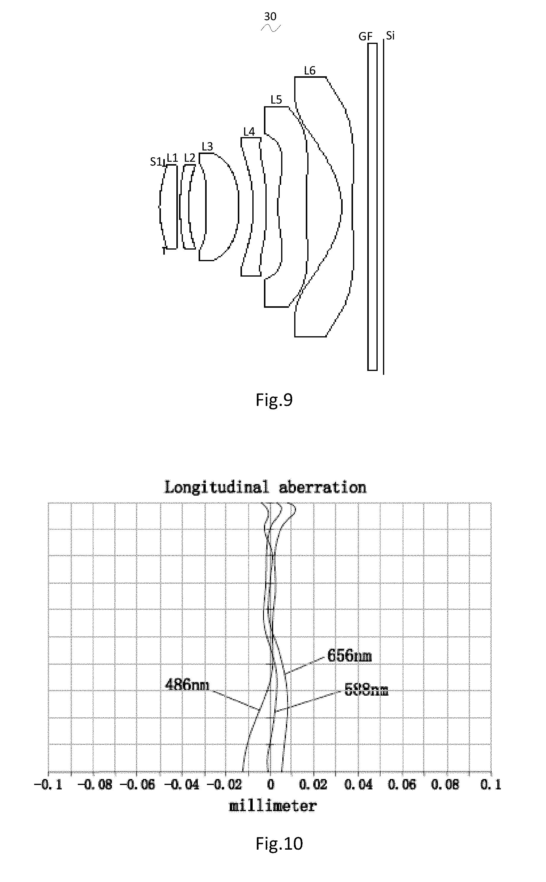
FIG. 9 is a schematic diagram of a camera optical lens in accordance with a third embodiment of the present invention;
FIG. 10 presents the longitudinal aberration of the camera optical lens shown in FIG. 9;
FIG. 11 presents the lateral color of the camera optical lens shown in FIG. 9;
FIG. 12 presents the field curvature and distortion of the camera optical lens shown in FIG. 9.
DETAILED DESCRIPTION OF THE EXEMPLARY EMBODIMENTS
The present disclosure will hereinafter be described in detail with reference to several exemplary embodiments. To make the technical problems to be solved, technical solutions and beneficial effects of the present disclosure more apparent, the present disclosure is described in further detail together with the figure and the embodiments. It should be understood the specific embodiments described hereby is only to explain the disclosure, not intended to limit the disclosure.
Embodiment 1
As referring to FIG. 1, the present invention provides a camera optical lens 10. FIG. 1 shows the camera optical lens 10 of embodiment 1 of the present invention, the camera optical lens 10 comprises 6 lenses. Specifically, from the object side to the image side, the camera optical lens 10 comprises in sequence: an aperture S1, a first lens L1, a second lens L2, a third lens L3, a fourth lens L4, a fifth lens L5 and a sixth lens L6. Optical element like optical filter GF can be arranged between the sixth lens L6 and the image surface Si. The first lens L1 is made of glass material, the second lens L2 is made of glass material, the third lens L3 is made of plastic material, the fourth lens L4 is made of plastic material, the fifth lens L5 is made of plastic material, the sixth lens L6 is made of plastic material.
Here, the focal length of the whole camera optical lens 10 is defined as f, the focal length of the first lens is defined as f1, condition 0.5f1/f10 fixes the positive refractive power of the first lens L1. If the lower limit of the set value is exceeded, although it benefits the ultra-thin development of lenses, but the positive refractive power of the first lens L1 will be too strong, problem like aberration is difficult to be corrected, and it is also unfavorable for wide-angle development of lens. On the contrary, if the upper limit of the set value is exceeded, the positive refractive power of the first lens becomes too weak, it is then difficult to develop ultra-thin lenses. Preferably, the following condition shall be satisfied, 0.68f1/f5.58.
Condition 1.7n12.2 fixes the refractive power n1 of the first lens L1, refractive power within this range benefits the ultra-thin development of lenses, and it also benefits the correction of aberration. Preferably, the following condition shall be satisfied, 1.7n11.9.
Condition 1.7n22.2 fixes the refractive power n2 of the second lens L2, refractive power within this range benefits the ultra-thin development of lenses, and it also benefits the correction of aberration. Preferably, the following condition shall be satisfied, 1.7n22.15.
Condition 0.052d1/TTL0.2 fixes the ratio between the thickness d1 on-axis of the first lens L1 and the total optical length TTL of the camera optical lens 10, a ratio within this range can benefit the ultra-thin development of lenses. Preferably, the following condition shall be satisfied, 0.065d1/TTL0.15.
When the focal length of the camera optical lens 10 of the present invention, the focal length of each lens, the refractive power of the related lens, and the total optical length, the thickness on-axis and the curvature radius of the camera optical lens satisfy the above conditions, the camera optical lens 10 has the advantage of high performance and satisfies the design requirement of low TTL.
In this embodiment, the object side surface of the first lens L1 is a convex object surface relative to the proximal axis, its image side surface is a concave surface relative to the proximal axis, and it has positive refractive power; the curvature radius of the object side surface of the first lens L1 is R1, the curvature radius of image side surface of the first lens L1 is R2, by meeting the condition -4.00(R1+R2)/(R1-R2)-1.14 the shape of the first lens can be reasonably controlled so that the system spherical aberration of the first lens can be effectively corrected; Preferably, the condition -2.50(R1+R2)/(R1-R2)-1.42 shall be satisfied.
The thickness on-axis of the first lens L1 is d1, they satisfy the following condition: 0.20d10.78, when the condition is meet, it is beneficial for realization of the ultra-thin lens. Preferably, the condition 0.32d10.62 shall be satisfied.
In this embodiment, the object side surface of the second lens L2 is a convex surface relative to the proximal axis, its image side surface is a concave surface relative to the proximal axis, and it has negative refractive power; the focal length of the whole camera optical lens 10 is f, the focal length of the second lens L2 is f2, the curvature radius of the object side surface of the second lens L2 is R3, the curvature radius of image side surface of the second lens L2 is R4 and the thickness on-axis of the second lens L2 is d3, they satisfy the following condition: -7.93f2/f-1.11, when the condition is met, the negative refractive power of the second lens L2 is controlled within reasonable scope, the spherical aberration caused by the first lens L1 which has positive refractive power and the field curvature of the system then can be reasonably and effectively balanced; the condition 1.36(R3+R4)/(R3-R4)12.14 fixes the shape of the second lens L2, when value is beyond this range, with the development into the direction of ultra-thin and wide-angle lenses, problem like on-axis chromatic aberration is difficult to be corrected; if the condition 0.10d30.39 is met, it is beneficial for the realization of ultra-thin lenses. Preferably, the following conditions shall be satisfied, -4.96f2/f-1.38; 2.17(R3+R4)/(R3-R4)9.71; 0.16d30.31.
In this embodiment, the image side surface of the third lens L3 is a convex surface relative to the proximal axis, and it has positive refractive power; the focal length of the whole camera optical lens 10 is f, the focal length of the third lens L3 is f3, the curvature radius of the object side surface of the third lens L3 is R5, the curvature radius of the image side surface of the third lens L3 is R6 and the thickness on-axis of the third lens L3 is d5, they satisfy the condition: 0.74f3/f2.65, by meeting this condition, it is helpful for the system to obtain good ability in balancing the field curvature, so that the image quality can be effectively improved; by meeting the condition 0.23(R5+R6)/(R5-R6)2.13 the shape of the third lens L3 can be effectively controlled, it is beneficial for the shaping of the third lens L3 and bad shaping and stress generation due to extra large curvature of surface of the third lens L3 can be avoided; when the condition 0.26d51.13 is met, it is beneficial for the realization of ultra-thin lenses. Preferably, the following conditions shall be satisfied: 1.19f3/f2.12; 0.37(R5+R6)/(R5-R6)1.70; 0.42d50.90.
In this embodiment, the object side surface of the fourth lens L4 is a concave surface relative to the proximal axis, its image side surface is a convex surface relative to the proximal axis, and it has negative refractive power; the focal length of the whole camera optical lens 10 is f, the focal length of the fourth lens L4 is f4, the curvature radius of the object side surface of the fourth lens L4 is R7, the curvature radius of the image side surface of the fourth lens L4 is R8 and the thickness on-axis of the fourth lens L4 is d7, they satisfy the condition: -4.68f4/f-1.13, the appropriate distribution of refractive power makes it possible that the system has better imaging quality and lower sensitivity; the condition -3.99(R7+R8)/(R7-R8)-1.00 fixes the shape of the fourth lens L4, when beyond this range, with the development into the direction of ultra-thin and wide-angle lens, the problem like chromatic aberration is difficult to be corrected; when the condition 0.15d70.84 is met, it is beneficial for realization of ultra-thin lenses. Preferably, the following conditions shall be satisfied, -2.93f4/f-1.42; -2.50(R7+R8)/(R7-R8)-1.25; 0.24d70.67.
In this embodiment, the object side surface of the fifth lens L5 is a convex surface relative to the proximal axis, its image side surface is a convex surface relative to the proximal axis, and it has positive refractive power; the focal length of the whole camera optical lens 10 is f, the focal length of the fifth lens L5 is f5, the curvature radius of the object side surface of the fifth lens L5 is R9, the curvature radius of the image side surface of the fifth lens L5 is R10 and the thickness on-axis of the fifth lens L5 is d9, they satisfy the condition: 0.53f5/f1.79, the limitation on the fifth lens L5 can effectively make the light angle of the camera lens flat and the tolerance sensitivity reduces; the condition -1.69(R9+R10)/(R9-R10)-0.55 fixes the shape of the fifth lens L5, when beyond this range, with the development into the direction of ultra-thin and wide-angle lens, the problem like off-axis chromatic aberration is difficult to be corrected; when the condition 0.28d91.00 is met, it is beneficial for the realization of ultra-thin lens. Preferably, the following conditions shall be satisfied: 0.84f5/f1.43; -1.05(R9+R10)/(R9-R10)-0.68; 0.45d90.80.
In this embodiment, the object side surface of the sixth lens L6 is a concave surface relative to the proximal axis, and it has negative refractive power; the focal length of the whole camera optical lens 10 is f, the focal length of the sixth lens L6 is f6, the curvature radius of the object side surface of the sixth lens L6 is R11, the curvature radius of the image side surface of the sixth lens L6 is R12 and the thickness on-axis of the sixth lens L6 is d11, they satisfy the condition: -1.42f6/f-0.44, the appropriate distribution of refractive power makes it possible that the system has better imaging quality and lower sensitivity; the condition -2.71(R11+R12)/(R11-R12)-0.54 fixes the shape of the sixth lens L6, when beyond this range, with the development into the direction of ultra-thin and wide-angle lenses, the problem like off-axis chromatic aberration is difficult to be corrected; when the condition 0.12d110.37, is met, it is beneficial for the realization of ultra-thin lens. Preferably, the following conditions shall be satisfied, -0.89f6/f-0.55; -1.69(R11+R12)/(R11-R12)-0.67; 0.20d110.30.
In this embodiment, the focal length of the whole camera optical lens 10 is f, a focal length of the first lens and the second lens combined is f12, they satisfy the condition: 0.75f12/f2.27. Hence, the chromatic aberration and the distortion of the camera optical lens can be eliminated, the back focal length of the camera optical lens can be suppressed, and the miniaturization of the camera optical lens can be sustained. Preferably, the following conditions shall be satisfied, 1.20f12/f1.81.
In this embodiment, the total optical length TTL of the camera optical lens 10 is less than or equal to 5.72 mm, it is beneficial for the realization of ultra-thin lenses. Preferably, the total optical length TTL of the camera optical lens 10 is less than or equal to 5.46 mm.
In this embodiment, the aperture F number of the camera optical lens 10 is less than or equal to 2.27. A large aperture has better imaging performance. Preferably, the aperture F number of the camera optical lens 10 is less than or equal to 2.22.
With such design, the total optical length TTL of the whole camera optical lens 10 can be made as short as possible, thus the miniaturization characteristics can be maintained.
In the following, an example will be used to describe the camera optical lens 10 of the present invention. The symbols recorded in each example are as follows. The unit of distance, radius and center thickness is mm.
TTL: Optical length (the distance on-axis from the object side surface to the image surface of the first lens L1).
Preferably, inflexion points and/or arrest points can also be arranged on the object side surface and/or image side surface of the lens, so that the demand for high quality imaging can be satisfied, the description below can be referred for specific implementable scheme.
The design information of the camera optical lens 10 in the first embodiment of the present invention is shown in the following, the unit of the focal length, distance, radius and center thickness is mm.
The design information of the camera optical lens 10 in the first embodiment of the present invention is shown in the tables 1 and 2.
TABLE-US-00001 TABLE 1 R d nd .nu. d S1 .infin. d0= -0.200 R1 1.942 d1= 0.452 nd1 1.7130 .nu. 1 53.87 R2 6.155 d2= 0.042 R3 6.196 d3= 0.237 nd2 1.7174 .nu. 2 29.52 R4 2.863 d4= 0.414 R5 12.835 d5= 0.555 nd3 1.5439 .nu. 3 55.95 R6 -4.705 d6= 0.141 R7 -3.663 d7= 0.557 nd4 1.6355 .nu. 4 23.97 R8 -18.325 d8= 0.384 R9 2.648 d9= 0.584 nd5 1.5352 .nu. 5 56.12 R10 -26.485 d10= 0.880 R11 -1.373 d11= 0.249 nd6 1.5352 .nu. 6 56.12 R12 -9.108 d12= 0.350 R13 .infin. d13= 0.210 ndg 1.5168 .nu. g 64.17 R14 .infin. d14= 0.144
In which, the meaning of the various symbols is as follows.
S1: Aperture;
R: The curvature radius of the optical surface, the central curvature radius in case of lens;
R1: The curvature radius of the object side surface of the first lens L1;
R2: The curvature radius of the image side surface of the first lens L1;
R3: The curvature radius of the object side surface of the second lens L2;
R4: The curvature radius of the image side surface of the second lens L2;
R5: The curvature radius of the object side surface of the third lens L3;
R6: The curvature radius of the image side surface of the third lens L3;
R7: The curvature radius of the object side surface of the fourth lens L4;
R8: The curvature radius of the image side surface of the fourth lens L4;
R9: The curvature radius of the object side surface of the fifth lens L5;
R10: The curvature radius of the image side surface of the fifth lens L5;
R11: The curvature radius of the object side surface of the sixth lens L6;
R12: The curvature radius of the image side surface of the sixth lens L6;
R13: The curvature radius of the object side surface of the seventh lens L7;
R14: The curvature radius of the image side surface of the seventh lens L7;
d: The thickness on-axis of the lens and the distance on-axis between the lens;
d0: The distance on-axis from aperture S1 to the object side surface of the first lens L1;
d1: The thickness on-axis of the first lens L1;
d2: The distance on-axis from the image side surface of the first lens L1 to the object side surface of the second lens L2;
d3: The thickness on-axis of the second lens L2;
d4: The distance on-axis from the image side surface of the second lens L2 to the object side surface of the third lens L3;
d5: The thickness on-axis of the third lens L3;
d6: The distance on-axis from the image side surface of the third lens L3 to the object side surface of the fourth lens L4;
d7: The thickness on-axis of the fourth lens L4;
d8: The distance on-axis from the image side surface of the fourth lens L4 to the object side surface of the fifth lens L5;
d9: The thickness on-axis of the fifth lens L5;
d10: The distance on-axis from the image side surface of the fifth lens L5 to the object side surface of the sixth lens L6;
d11: The thickness on-axis of the sixth lens L6;
d12: The distance on-axis from the image side surface of the sixth lens L6 to the object side surface of the seventh lens L7;
d13: The thickness on-axis of the seventh lens L7;
d14: The distance on-axis from the image side surface of the seventh lens L7 to the object side surface of the optical filter GF;
nd: The refractive power of the d line;
nd1: The refractive power of the d line of the first lens L1;
nd2: The refractive power of the d line of the second lens L2;
nd3: The refractive power of the d line of the third lens L3;
nd4: The refractive power of the d line of the fourth lens L4;
nd5: The refractive power of the d line of the fifth lens L5;
nd6: The refractive power of the d line of the sixth lens L6;
ndg: The refractive power of the d line of the optical filter GF;
vd: The abbe number;
v1: The abbe number of the first lens L1;
v2: The abbe number of the second lens L2;
v3: The abbe number of the third lens L3;
v4: The abbe number of the fourth lens L4;
v5: The abbe number of the fifth lens L5;
v6: The abbe number of the sixth lens L6;
vg: The abbe number of the optical filter GF;
Table 2 shows the aspherical surface data of the camera optical lens 10 in the embodiment 1 of the present invention.
TABLE-US-00002 TABLE 2 Conic Index Aspherical Surface Index k A4 A6 A8 A10 A12 A14 A16 R1 -4.0131E-01 5.4875E-03 -5.7657E-03 -1.6701E-02 2.4188E-03 -7.0798E-03 7.1176E-03 -1.3038E-02 R2 1.4275E+01 -1.3902E-01 1.0205E-01 -2.6998E-02 -3.6121E-02 -4.8142E-03 -5.6945E-03 6.7324E-03 R3 2.7150E+01 -1.5639E-01 1.9265E-01 -5.6332E-02 -3.5761E-02 -2.7411E-03 7.3086E-03 6.9318E-04 R4 5.1851E+00 -2.8449E-02 7.1515E-02 -3.6495E-02 1.4796E-02 -2.9836E-02 4.2749E-02 -3.0180E-02 R5 0.0000E+00 -4.4241E-02 -2.5794E-02 -1.6507E-02 -2.1788E-02 1.9007E-02 -2.7886E-02 2.0410E-02 R6 -7.5641E-01 -6.6458E-02 -2.6168E-02 -7.0032E-03 3.1658E-03 -9.9180E-03 1.0345E-02 -4.1254E-03 R7 -2.4209E+01 -1.2874E-01 7.7896E-02 -9.4005E-03 -5.6210E-05 1.6249E-03 -1.7300E-03 1.4503E-04 R8 -3.3890E+02 -1.1592E-01 6.0332E-02 -1.2046E-03 -2.1949E-03 -3.5337E-04 1.0696E-04 4.7125E-06 R9 -1.9060E+00 -5.6562E-02 2.1902E-03 -2.8326E-04 -9.1489E-04 5.9179E-04 -1.9261E-04 2.1857E-05 R10 -1.1144E+02 4.4936E-02 -3.2135E-02 8.8983E-03 -1.5651E-03 1.7755E-04 -1.5672E-05 8.9567E-07 R11 -1.6626E+00 2.2016E-02 -1.5672E-02 5.8251E-03 -9.8872E-04 8.9870E-05 -4.2233E-06 7.5540E-08 R12 -4.4839E+01 5.3995E-03 -8.2490E-03 2.6601E-03 -5.1119E-04 5.2692E-05 -2.6701E-06 5.7000E-08
Among them, K is a conic index, A4, A6, A8, A10, A12, A14, A16 are aspheric surface indexes.
IH: Image height y=(x.sup.2/R)/[1+{1-(k+1)(x.sup.2/R.sup.2)}.sup.1/2]+A4x.sup.4+A6x.sup.6+- A8x.sup.8+A10x.sup.10+A12x.sup.12+A14x.sup.14+A16x.sup.16 (1)
For convenience, the aspheric surface of each lens surface uses the aspheric surfaces shown in the above condition (1). However, the present invention is not limited to the aspherical polynomials form shown in the condition (1).
Table 3 and table 4 show the inflexion points and the arrest point design data of the camera optical lens 10 lens in embodiment 1 of the present invention. In which, P1R1 and P1R2 represent respectively the object side surface and image side surface of the first lens L1, P2R1 and P2R2 represent respectively the object side surface and image side surface of the second lens L2, P3R1 and P3R2 represent respectively the object side surface and image side surface of the third lens L3, P4R1 and P4R2 represent respectively the object side surface and image side surface of the fourth lens L4, P5R1 and P5R2 represent respectively the object side surface and image side surface of the fifth lens L5, P6R1 and P6R2 represent respectively the object side surface and image side surface of the sixth lens L6. The data in the column named "inflexion point position" are the vertical distances from the inflexion points arranged on each lens surface to the optic axis of the camera optical lens 10. The data in the column named "arrest point position" are the vertical distances from the arrest points arranged on each lens surface to the optic axis of the camera optical lens 10.
TABLE-US-00003 TABLE 3 inflexion point inflexion point inflexion point number position 1 position 2 P1R1 1 0.845 P1R2 1 0.375 P2R1 1 0.945 P2R2 0 P3R1 1 0.355 P3R2 0 P4R1 2 0.945 1.195 P4R2 2 0.955 1.575 P5R1 1 0.725 P5R2 2 0.285 0.875 P6R1 1 1.555 P6R2 1 2.665
TABLE-US-00004 TABLE 4 arrest point arrest point arrest point number position 1 position 2 P1R1 0 P1R2 1 0.725 P2R1 0 P2R2 0 P3R1 1 0.565 P3R2 0 P4R1 0 P4R2 0 P5R1 1 1.245 P5R2 2 0.535 1.085 P6R1 1 2.565 P6R2 0
FIG. 2 and FIG. 3 show the longitudinal aberration and lateral color schematic diagrams after light with a wavelength of 486 nm, 588 nm and 656 nm passes the camera optical lens 10 in the first embodiment. FIG. 4 shows the field curvature and distortion schematic diagrams after light with a wavelength of 588 nm passes the camera optical lens 10 in the first embodiment, the field curvature S in FIG. 4 is a field curvature in the sagittal direction, T is a field curvature in the meridian direction.
Table 13 shows the various values of the examples 1, 2, 3 and the values corresponding with the parameters which are already specified in the conditions.
As shown in Table 13, the first embodiment satisfies the various conditions.
In this embodiment, the pupil entering diameter of the camera optical lens is 1.954 mm, the full vision field image height is 3.928 mm, the vision field angle in the diagonal direction is 84.56.degree., it has wide-angle and is ultra-thin, its on-axis and off-axis chromatic aberrations are fully corrected, and it has excellent optical characteristics.
Embodiment 2
Embodiment 2 is basically the same as embodiment 1, the meaning of its symbols is the same as that of embodiment 1, in the following, only the differences are described.
Table 5 and table 6 show the design data of the camera optical lens 20 in embodiment 2 of the present invention.
TABLE-US-00005 TABLE 5 R d nd .nu. d S1 .infin. d0= -0.150 R1 2.072 d1= 0.517 nd1 1.7130 .nu. 1 53.87 R2 7.919 d2= 0.051 R3 5.715 d3= 0.262 nd2 1.9020 .nu. 2 25.10 R4 2.977 d4= 0.406 R5 50.769 d5= 0.526 nd3 1.5439 .nu. 3 55.95 R6 -4.527 d6= 0.235 R7 -4.232 d7= 0.415 nd4 1.6355 .nu. 4 23.97 R8 -12.716 d8= 0.385 R9 2.717 d9= 0.562 nd5 1.5352 .nu. 5 56.12 R10 -30.644 d10= 0.892 R11 -1.383 d11= 0.250 nd6 1.5352 .nu. 6 56.12 R12 -13.048 d12= 0.350 R13 .infin. d13= 0.210 ndg 1.5168 .nu. g 64.17 R14 .infin. d14= 0.140
Table 6 shows the aspherical surface data of each lens of the camera optical lens 20 in embodiment 2 of the present invention.
TABLE-US-00006 TABLE 6 Conic Index Aspherical Surface Index k A4 A6 A8 A10 A12 A14 A16 R1 -5.7847E-01 2.6987E-03 -1.3069E-02 -1.9883E-02 4.4578E-03 -2.2494E-03 1.1772E-02 -1.0663E-02 R2 1.8669E+01 -1.3929E-01 1.0567E-01 -2.0397E-02 -2.9161E-02 -5.8764E-04 -5.3184E-03 5.5100E-03 R3 2.4410E+01 -1.3976E-01 1.9283E-01 -5.9669E-02 -3.3790E-02 4.0706E-03 1.1422E-02 -8.9489E-03 R4 5.2438E+00 -3.7091E-02 7.8438E-02 -3.2484E-02 1.3589E-02 -3.2949E-02 4.1205E-02 -2.6991E-02 R5 0.0000E+00 -6.3687E-02 -2.5134E-02 -1.5709E-02 -1.7731E-02 2.5837E-02 - -2.4250E-02 1.7167E-02 R6 6.1898E-01 -6.7853E-02 -2.8429E-02 -3.2868E-03 4.3530E-03 -1.0856E-02 9.8162E-03 -3.1482E-03 R7 -3.9136E+01 -1.2562E-01 7.7047E-02 -1.0289E-02 -4.2168E-04 1.6017E-03 -1.6130E-03 2.8062E-04 R8 -4.1980E+01 -1.1642E-01 6.0733E-02 -1.1305E-03 -2.2065E-03 -3.6561E-04 1.0380E-04 6.0181E-06 R9 -1.6941E+00 -5.4830E-02 2.4479E-03 -4.3614E-04 -9.2087E-04 6.0126E-04 -1.9266E-04 2.0535E-05 R10 -7.5005E+01 4.6333E-02 -3.2254E-02 8.8596E-03 -1.5689E-03 1.7763E-04 -1.5575E-05 9.0900E-07 R11 -1.6423E+00 2.1951E-02 -1.5670E-02 5.8252E-03 -9.8881E-04 8.9848E-05 -4.2257E-06 7.6128E-08 R12 -4.6681E+01 5.6219E-03 -8.2229E-03 2.6625E-03 -5.1113E-04 5.2673E-05 -2.6746E-06 5.6282E-08
Table 7 and table 8 show the inflexion points and the arrest point design data of the camera optical lens 20 lens in the second embodiment of the present invention.
TABLE-US-00007 TABLE 7 inflexion point inflexion point inflexion point number position 1 position 2 P1R1 1 0.865 P1R2 1 0.315 P2R1 1 0.985 P2R2 0 P3R1 1 0.165 P3R2 0 P4R1 2 0.945 1.265 P4R2 2 0.965 1.565 P5R1 1 0.735 P5R2 2 0.265 0.895 P6R1 1 1.565 P6R2 1 2.695
TABLE-US-00008 TABLE 8 arrest point arrest point arrest point number position 1 position 2 P1R1 0 P1R2 1 0.615 P2R1 0 P2R2 0 P3R1 1 0.275 P3R2 0 P4R1 0 P4R2 1 1.415 P5R1 1 1.255 P5R2 2 0.475 1.145 P6R1 1 2.585 P6R2 0
FIG. 6 and FIG. 7 show the longitudinal aberration and lateral color schematic diagrams after light with a wavelength of 486 nm, 588 nm and 656 nm passes the camera optical lens 20 in the second embodiment. FIG. 8 shows the field curvature and distortion schematic diagrams after light with a wavelength of 588 nm passes the camera optical lens 20 in the second embodiment.
As shown in Table 13, the second embodiment satisfies the various conditions.
In this embodiment, the pupil entering diameter of the camera optical lens is 1.975 mm, the full vision field image height is 3.928 mm, the vision field angle in the diagonal direction is 83.33.degree., it has wide-angle and is ultra-thin, its on-axis and off-axis chromatic aberrations are fully corrected, and it has excellent optical characteristics.
Embodiment 3
Embodiment 3 is basically the same as embodiment 1, the meaning of its symbols is the same as that of embodiment 1, in the following, only the differences are described.
The design information of the camera optical lens 30 in the third embodiment of the present invention is shown in the tables 9 and 10.
TABLE-US-00009 TABLE 9 R d nd .nu. d S1 .infin. d0= -0.120 R1 2.350 d1= 0.399 nd1 1.7130 .nu. 1 53.87 R2 7.050 d2= 0.074 R3 4.575 d3= 0.200 nd2 2.1021 .nu. 2 16.77 R4 3.568 d4= 0.405 R5 -17.014 d5= 0.753 nd3 1.5439 .nu. 3 55.95 R6 -2.946 d6= 0.325 R7 -3.979 d7= 0.300 nd4 1.6355 .nu. 4 23.97 R8 -13.548 d8= 0.272 R9 2.847 d9= 0.670 nd5 1.5352 .nu. 5 56.12 R10 -33.382 d10= 0.795 R11 -1.618 d11= 0.250 nd6 1.5352 .nu. 6 56.12 R12 15.004 d12= 0.350 R13 .infin. d13= 0.210 ndg 1.5168 .nu. g 64.17 R14 .infin. d14= 0.140
Table 10 shows the aspherical surface data of each lens of the camera optical lens 30 in embodiment 3 of the present invention.
TABLE-US-00010 TABLE 10 Conic Index Aspherical Surface Index k A4 A6 A8 A10 A12 A14 A16 R1 -1.2945E+00 -5.0412E-03 -1.8391E-02 -2.0147E-02 9.6635E-03 -4.3726E-03 2.0618E-03 -6.2452E-03 R2 1.8892E+01 -1.2253E-01 9.1923E-02 -5.3867E-02 -3.8323E-02 2.3555E-02 2.1279E-02 -2.0812E-02 R3 1.3216E+01 -1.0294E-01 1.5727E-01 -7.5583E-02 -2.9024E-02 2.1977E-02 2.5761E-02 -2.8052E-02 R4 5.5431E+00 -4.0859E-02 8.8884E-02 -4.2307E-02 1.1265E-02 -2.6896E-02 3.8894E-02 -2.6258E-02 R5 0.0000E+00 -8.2708E-02 -1.7629E-03 -4.3605E-02 -2.0974E-02 4.4913E-02 - -1.5194E-02 -9.5994E-03 R6 2.5890E+00 -6.7792E-02 -1.8505E-02 6.0148E-03 2.0723E-03 -1.1500E-02 1.0471E-02 -4.2810E-03 R7 -4.2276E+01 -1.2556E-01 7.1001E-02 -8.6939E-03 -6.9502E-04 1.2442E-03 -1.4794E-03 3.0937E-04 R8 -2.3528E+01 -1.1154E-01 6.1325E-02 -2.6444E-03 -2.2013E-03 -3.0764E-04 1.1119E-04 8.5021E-06 R9 -6.8655E+00 -6.0295E-02 4.3380E-03 -1.5451E-03 -1.5508E-03 7.4994E-04 -9.3061E-05 -2.4478E-05 R10 1.9027E+02 4.3751E-02 -3.1939E-02 9.0921E-03 -1.5677E-03 1.7104E-04 -1.5375E-05 1.0031E-06 R11 -1.6705E+00 2.0510E-02 -1.5670E-02 5.8296E-03 -9.8747E-04 9.0018E-05 -4.2274E-06 7.0300E-08 R12 -5.9762E+02 2.2121E-03 -8.1174E-03 2.6984E-03 -5.0863E-04 5.2620E-05 -2.6959E-06 5.3502E-08
Table 11 and table 12 show the inflexion points and the arrest point design data of the camera optical lens 30 lens in embodiment 3 of the present invention.
TABLE-US-00011 TABLE 11 inflexion point inflexion point inflexion point inflexion point number position 1 position 2 position 3 P1R1 1 0.765 P1R2 1 0.365 P2R1 1 0.935 P2R2 0 P3R1 0 P3R2 0 P4R1 2 1.005 1.225 P4R2 1 0.965 P5R1 1 0.605 P5R2 3 0.265 0.855 2.315 P6R1 1 1.585 P6R2 2 0.655 2.725
TABLE-US-00012 TABLE 12 arrest point arrest point arrest point number position 1 position 2 P1R1 0 P1R2 1 0.665 P2R1 0 P2R2 0 P3R1 0 P3R2 0 P4R1 0 P4R2 1 1.435 P5R1 1 1.045 P5R2 2 0.475 1.085 P6R1 0 P6R2 1 1.105
FIG. 10 and FIG. 11 show the longitudinal aberration and lateral color schematic diagrams after light with a wavelength of 486 nm, 588 nm and 656 nm passes the camera optical lens 30 in the third embodiment. FIG. 12 shows the field curvature and distortion schematic diagrams after light with a wavelength of 588 nm passes the camera optical lens 30 in the third embodiment.
The following table 13, in accordance with the above conditions, lists the values in this embodiment corresponding with each condition expression. Apparently, the camera optical system of this embodiment satisfies the above conditions.
In this embodiment, the pupil entering diameter of the camera optical lens is 1.882 mm, the full vision field image height is 3.928 mm, the vision field angle in the diagonal direction is 86.12.degree., it has wide-angle and is ultra-thin, its on-axis and off-axis chromatic aberrations are fully corrected, and it has excellent optical characteristics.
TABLE-US-00013 TABLE 13 Embodi- Embodi- Embodi- ment 1 ment 2 ment 3 f 4.299 4.346 4.141 f1 3.810 3.795 4.775 f2 -7.647 -7.218 -16.428 f3 6.401 7.667 6.430 f4 -7.313 -10.174 -8.974 f5 4.530 4.691 4.934 f6 -3.054 -2.913 -2.715 f12 6.456 6.573 6.253 (R1 + R2)/(R1 - R2) -1.922 -1.709 -2.000 (R3 + R4)/(R3 - R4) 2.718 3.175 8.090 (R5 + R6)/(R5 - R6) 0.464 0.836 1.419 (R7 + R8)/(R7 - R8) -1.500 -1.997 -1.832 (R9 + R10)/(R9 - R10) -0.818 -0.837 -0.843 (R11 + R12)/(R11 - R12) -1.355 -1.237 -0.805 f1/f 0.886 0.873 1.153 f2/f -1.779 -1.661 -3.967 f3/f 1.489 1.764 1.553 f4/f -1.701 -2.341 -2.167 f5/f 1.054 1.079 1.191 f6/f -0.710 -0.670 -0.656 f12/f 1.502 1.512 1.510 d1 0.452 0.517 0.399 d3 0.237 0.262 0.200 d5 0.555 0.526 0.753 d7 0.557 0.415 0.300 d9 0.584 0.562 0.670 d11 0.249 0.250 0.250 Fno 2.200 2.200 2.200 TTL 5.200 5.200 5.144 d1/TTL 0.087 0.099 0.078 d3/TTL 0.046 0.050 0.039 d5/TTL 0.107 0.101 0.146 d7/TTL 0.107 0.080 0.058 d9/TTL 0.112 0.108 0.130 d11/TTL 0.048 0.048 0.049 n1 1.7130 1.7130 1.7130 n2 1.7174 1.9020 2.1021 n3 1.5439 1.5439 1.5439 n4 1.6355 1.6355 1.6355 n5 1.5352 1.5352 1.5352 n6 1.5352 1.5352 1.5352 v1 53.8671 53.8671 53.8671 v2 29.5181 25.1014 16.7714 v3 55.9524 55.9524 55.9524 v4 23.9718 23.9718 23.9718 v5 56.1153 56.1153 56.1153 v6 56.1153 56.1153 56.1153
It is to be understood, however, that even though numerous characteristics and advantages of the present exemplary embodiments have been set forth in the foregoing description, together with details of the structures and functions of the embodiments, the disclosure is illustrative only, and changes may be made in detail, especially in matters of shape, size, and arrangement of parts within the principles of the invention to the full extent indicated by the broad general meaning of the terms where the appended claims are expressed.
* * * * *
D00000
D00001
D00002
D00003
D00004
D00005
D00006
D00007
P00001
XML
uspto.report is an independent third-party trademark research tool that is not affiliated, endorsed, or sponsored by the United States Patent and Trademark Office (USPTO) or any other governmental organization. The information provided by uspto.report is based on publicly available data at the time of writing and is intended for informational purposes only.
While we strive to provide accurate and up-to-date information, we do not guarantee the accuracy, completeness, reliability, or suitability of the information displayed on this site. The use of this site is at your own risk. Any reliance you place on such information is therefore strictly at your own risk.
All official trademark data, including owner information, should be verified by visiting the official USPTO website at www.uspto.gov. This site is not intended to replace professional legal advice and should not be used as a substitute for consulting with a legal professional who is knowledgeable about trademark law.