Method of operating a laboratory sample distribution system, laboratory sample distribution system and a laboratory automation system
Huber , et al. July 16, 2
U.S. patent number 10,352,953 [Application Number 15/154,144] was granted by the patent office on 2019-07-16 for method of operating a laboratory sample distribution system, laboratory sample distribution system and a laboratory automation system. This patent grant is currently assigned to Roche Diagnostics Operations, Inc.. The grantee listed for this patent is Roche Diagnostics Operations, Inc.. Invention is credited to Oliver Denninger, Timo Fleischmann, Tobias Huber, Domenic Jenz, Mohammadreza Mahmudimanesh, Namitha Mallikarjunaiah, Achim Sinz.

| United States Patent | 10,352,953 |
| Huber , et al. | July 16, 2019 |
Method of operating a laboratory sample distribution system, laboratory sample distribution system and a laboratory automation system
Abstract
A method of operating a laboratory sample distribution system is disclosed. The laboratory sample distribution system comprises a plurality of sample container carriers. The sample container carriers carry one or more sample containers. The sample containers comprise samples to be analyzed by a plurality of laboratory stations. The system also comprises a transport plane. The transport plane supports the sample container carriers. The transport plane comprises a plurality of transfer locations. The transfer locations are assigned to corresponding laboratory stations. The system also comprises a drive. The drive moves the sample container carriers on the transport plane. The method comprises, during an initialization of the laboratory sample distribution system, pre-calculating routes depending on the transfer locations and, after the initialization of the laboratory sample distribution system, controlling the drive such that the sample container carriers move along the pre-calculated routes.
| Inventors: | Huber; Tobias (Backnang, DE), Sinz; Achim (Waiblingen, DE), Mallikarjunaiah; Namitha (Kornwestheim, DE), Denninger; Oliver (Karlsruhe, DE), Mahmudimanesh; Mohammadreza (Griesheim, DE), Fleischmann; Timo (Esslingen, DE), Jenz; Domenic (Esslingen, DE) | ||||||||||
|---|---|---|---|---|---|---|---|---|---|---|---|
| Applicant: |
|
||||||||||
| Assignee: | Roche Diagnostics Operations,
Inc. (Indianapolis, IN) |
||||||||||
| Family ID: | 53264501 | ||||||||||
| Appl. No.: | 15/154,144 | ||||||||||
| Filed: | May 13, 2016 |
Prior Publication Data
| Document Identifier | Publication Date | |
|---|---|---|
| US 20160341751 A1 | Nov 24, 2016 | |
Foreign Application Priority Data
| May 22, 2015 [EP] | 15168780 | |||
| Current U.S. Class: | 1/1 |
| Current CPC Class: | B65G 43/00 (20130101); G01N 35/00584 (20130101); G01N 35/04 (20130101); G01N 35/0092 (20130101); G01N 2035/0406 (20130101); G01N 2035/0462 (20130101); G01N 2035/0477 (20130101) |
| Current International Class: | G01N 35/04 (20060101); B65G 43/00 (20060101); G01N 35/00 (20060101) |
References Cited [Referenced By]
U.S. Patent Documents
| 3273727 | September 1966 | Rogers et al. |
| 3653485 | April 1972 | Donlon |
| 3901656 | August 1975 | Durkos et al. |
| 4150666 | April 1979 | Brush |
| 4395164 | July 1983 | Beltrop |
| 4544068 | October 1985 | Cohen |
| 4771237 | September 1988 | Daley |
| 5120506 | June 1992 | Saito et al. |
| 5295570 | March 1994 | Grechsch et al. |
| 5309049 | May 1994 | Kawada et al. |
| 5457368 | October 1995 | Jacobsen et al. |
| 5523131 | June 1996 | Isaacs et al. |
| 5530345 | June 1996 | Murari et al. |
| 5636548 | June 1997 | Dunn et al. |
| 5641054 | June 1997 | Mori et al. |
| 5651941 | July 1997 | Stark et al. |
| 5720377 | February 1998 | Lapeus et al. |
| 5735387 | April 1998 | Polaniec et al. |
| 5788929 | August 1998 | Nesti |
| 6045319 | April 2000 | Uchida et al. |
| 6062398 | May 2000 | Talmayr |
| 6141602 | October 2000 | Igarashi et al. |
| 6151535 | November 2000 | Ehlers |
| 6184596 | February 2001 | Ohzeki |
| 6191507 | February 2001 | Peltier et al. |
| 6206176 | March 2001 | Blonigan et al. |
| 6255614 | July 2001 | Yamakawa et al. |
| 6260360 | July 2001 | Wheeler |
| 6279728 | August 2001 | Jung et al. |
| 6293750 | September 2001 | Cohen et al. |
| 6429016 | August 2002 | McNeil |
| 6444171 | September 2002 | Sakazume et al. |
| 6571934 | June 2003 | Thompson et al. |
| 7028831 | April 2006 | Veiner |
| 7078082 | July 2006 | Adams |
| 7122158 | October 2006 | Itoh |
| 7278532 | October 2007 | Martin |
| 7326565 | February 2008 | Yokoi et al. |
| 7425305 | September 2008 | Itoh |
| 7428957 | September 2008 | Schaefer |
| 7578383 | August 2009 | Itoh |
| 7597187 | October 2009 | Bausenwein et al. |
| 7850914 | December 2010 | Veiner et al. |
| 7858033 | December 2010 | Itoh |
| 7875254 | January 2011 | Garton |
| 7939484 | May 2011 | Loeffler et al. |
| 8240460 | August 2012 | Bleau et al. |
| 8281888 | October 2012 | Bergmann |
| 8502422 | August 2013 | Lykkegaard |
| 8796186 | August 2014 | Shirazi |
| 8833544 | September 2014 | Stoeckle et al. |
| 9211543 | December 2015 | Ohga et al. |
| 9239335 | January 2016 | Heise |
| 2002/0009391 | January 2002 | Marquiss et al. |
| 2003/0092185 | May 2003 | Qureshi et al. |
| 2004/0050836 | March 2004 | Nesbitt et al. |
| 2004/0084531 | May 2004 | Itoh |
| 2005/0061622 | March 2005 | Martin |
| 2005/0109580 | May 2005 | Thompson |
| 2005/0194333 | September 2005 | Veiner et al. |
| 2005/0196320 | September 2005 | Veiner et al. |
| 2005/0226770 | October 2005 | Allen et al. |
| 2005/0242963 | November 2005 | Oldham et al. |
| 2005/0247790 | November 2005 | Itoh |
| 2005/0260101 | November 2005 | Nauck et al. |
| 2005/0271555 | December 2005 | Itoh |
| 2006/0000296 | January 2006 | Salter |
| 2006/0047303 | March 2006 | Ortiz et al. |
| 2006/0219524 | October 2006 | Kelly et al. |
| 2007/0116611 | May 2007 | DeMarco |
| 2007/0210090 | September 2007 | Sixt et al. |
| 2007/0248496 | October 2007 | Bondioli et al. |
| 2007/0276558 | November 2007 | Kim |
| 2008/0012511 | January 2008 | Ono |
| 2008/0029368 | February 2008 | Komori |
| 2008/0056328 | March 2008 | Rund et al. |
| 2008/0131961 | June 2008 | Crees et al. |
| 2008/0286162 | November 2008 | Onizawa et al. |
| 2009/0004732 | January 2009 | LaBarre et al. |
| 2009/0022625 | January 2009 | Lee et al. |
| 2009/0081771 | March 2009 | Breidford et al. |
| 2009/0128139 | May 2009 | Drenth |
| 2009/0142844 | June 2009 | LeComte |
| 2009/0180931 | July 2009 | Silbert et al. |
| 2009/0322486 | December 2009 | Gerstel |
| 2010/0000250 | January 2010 | Sixt |
| 2010/0152895 | June 2010 | Dai |
| 2010/0175943 | July 2010 | Bergmann |
| 2010/0186618 | July 2010 | King et al. |
| 2010/0255529 | October 2010 | Cocola et al. |
| 2010/0300831 | December 2010 | Pedrazzini |
| 2010/0312379 | December 2010 | Pedrazzini |
| 2011/0050213 | March 2011 | Furukawa |
| 2011/0124038 | May 2011 | Bishop et al. |
| 2011/0172128 | July 2011 | Davies et al. |
| 2011/0186406 | August 2011 | Kraus |
| 2011/0287447 | November 2011 | Norderhaug |
| 2012/0037696 | February 2012 | Lavi |
| 2012/0129673 | May 2012 | Fukugaki et al. |
| 2012/0178170 | July 2012 | Van Praet |
| 2012/0211645 | August 2012 | Tullo et al. |
| 2012/0275885 | November 2012 | Furrer et al. |
| 2012/0282683 | November 2012 | Mototsu |
| 2012/0295358 | November 2012 | Ariff et al. |
| 2012/0310401 | December 2012 | Shah |
| 2013/0034410 | February 2013 | Heise et al. |
| 2013/0126302 | May 2013 | Johns et al. |
| 2013/0153677 | June 2013 | Leen et al. |
| 2013/0180824 | July 2013 | Kleinikkink et al. |
| 2013/0263622 | October 2013 | Mullen et al. |
| 2013/0322992 | December 2013 | Pedrazzini |
| 2014/0170023 | June 2014 | Saito et al. |
| 2014/0202829 | July 2014 | Eberhardt |
| 2014/0231217 | August 2014 | Denninger et al. |
| 2014/0234065 | August 2014 | Heise et al. |
| 2014/0234949 | August 2014 | Wasson et al. |
| 2015/0014125 | January 2015 | Hecht |
| 2015/0166265 | June 2015 | Pollack et al. |
| 2015/0233956 | August 2015 | Buehr |
| 2015/0233957 | August 2015 | Riether |
| 2015/0241457 | August 2015 | Miller |
| 2015/0273468 | October 2015 | Croquette et al. |
| 2015/0273691 | October 2015 | Pollack |
| 2015/0276775 | October 2015 | Mellars et al. |
| 2015/0276776 | October 2015 | Riether |
| 2015/0276777 | October 2015 | Riether |
| 2015/0276778 | October 2015 | Riether |
| 2015/0276781 | October 2015 | Riether |
| 2015/0276782 | October 2015 | Riether |
| 2015/0360876 | December 2015 | Sinz |
| 2015/0360878 | December 2015 | Denninger et al. |
| 2016/0003859 | January 2016 | Wenczel et al. |
| 2016/0025756 | January 2016 | Pollack et al. |
| 2016/0054341 | February 2016 | Edelmann |
| 2016/0054344 | February 2016 | Heise et al. |
| 2016/0069715 | March 2016 | Sinz |
| 2016/0077120 | March 2016 | Riether |
| 2016/0097786 | April 2016 | Malinkowski et al. |
| 2016/0229565 | August 2016 | Margner |
| 2016/0274137 | September 2016 | Baer |
| 2016/0282378 | September 2016 | Malinowski et al. |
| 2016/0341750 | November 2016 | Sinz et al. |
| 2017/0059599 | March 2017 | Riether |
| 2017/0096307 | April 2017 | Mahmudimanesh et al. |
| 2017/0097372 | April 2017 | Heise et al. |
| 2017/0101277 | April 2017 | Malinowski |
| 2017/0108522 | April 2017 | Baer |
| 2017/0131307 | May 2017 | Pedain |
| 2017/0131309 | May 2017 | Pedain |
| 2017/0131310 | May 2017 | Volz et al. |
| 2017/0138971 | May 2017 | Heise et al. |
| 2017/0160299 | June 2017 | Schneider et al. |
| 2017/0168079 | June 2017 | Sinz |
| 2017/0174448 | June 2017 | Sinz |
| 2017/0184622 | June 2017 | Sinz et al. |
| 2017/0248623 | August 2017 | Kaeppeli et al. |
| 2017/0248624 | August 2017 | Kaeppeli et al. |
| 2017/0363608 | December 2017 | Sinz |
| 2018/0067141 | March 2018 | Mahmudimanesh et al. |
| 2018/0074087 | March 2018 | Heise et al. |
| 2018/0106821 | April 2018 | Vollenweider et al. |
| 2018/0128848 | May 2018 | Schneider et al. |
| 2018/0156835 | June 2018 | Hassan |
| 2018/0188280 | July 2018 | Malinowski |
| 2018/0210000 | July 2018 | van Mierlo |
| 2018/0210001 | July 2018 | Reza |
| 2018/0217174 | August 2018 | Malinowski |
| 2018/0217176 | August 2018 | Sinz et al. |
| 2018/0224476 | August 2018 | Birrer et al. |
| 2018/0348244 | December 2018 | Ren |
| 2018/0348245 | December 2018 | Schneider et al. |
| 2019/0018027 | January 2019 | Hoehnel |
| 2019/0076845 | March 2019 | Huber et al. |
| 2019/0076846 | March 2019 | Durco et al. |
| 2019/0086433 | March 2019 | Hermann et al. |
| 2019/0094251 | March 2019 | Malinowski |
| 2019/0094252 | March 2019 | Waser et al. |
| 2019/0101468 | April 2019 | Haldar |
| 201045617 | Apr 2008 | CN | |||
| 102109530 | Jun 2011 | CN | |||
| 3909786 | Sep 1990 | DE | |||
| 102012000665 | Aug 2012 | DE | |||
| 102011090044 | Jul 2013 | DE | |||
| 0601213 | Oct 1992 | EP | |||
| 0775650 | May 1997 | EP | |||
| 0896936 | Feb 1999 | EP | |||
| 0916406 | May 1999 | EP | |||
| 1122194 | Aug 2001 | EP | |||
| 1524525 | Apr 2005 | EP | |||
| 2119643 | Nov 2009 | EP | |||
| 2148117 | Jan 2010 | EP | |||
| 2327646 | Jun 2011 | EP | |||
| 2447701 | May 2012 | EP | |||
| 2500871 | Sep 2012 | EP | |||
| 2502675 | Sep 2012 | EP | |||
| 2887071 | Jun 2015 | EP | |||
| 2165515 | Apr 1986 | GB | |||
| S56-147209 | Nov 1981 | JP | |||
| 60-223481 | Nov 1985 | JP | |||
| 61-081323 | Apr 1986 | JP | |||
| S61-069604 | Apr 1986 | JP | |||
| S61-094925 | May 1986 | JP | |||
| S61-174031 | Aug 1986 | JP | |||
| S61-217434 | Sep 1986 | JP | |||
| S62-100161 | May 1987 | JP | |||
| S63-31918 | Feb 1988 | JP | |||
| S63-48169 | Feb 1988 | JP | |||
| S63-82433 | May 1988 | JP | |||
| S63-290101 | Nov 1988 | JP | |||
| 01-148966 | Jun 1989 | JP | |||
| H01-266860 | Oct 1989 | JP | |||
| H02-87903 | Mar 1990 | JP | |||
| 03-192013 | Aug 1991 | JP | |||
| H03-38704 | Aug 1991 | JP | |||
| H04-127063 | Apr 1992 | JP | |||
| H05-69350 | Mar 1993 | JP | |||
| H05-142232 | Jun 1993 | JP | |||
| H05-180847 | Jul 1993 | JP | |||
| 06-268808 | Apr 1994 | JP | |||
| H06-148198 | May 1994 | JP | |||
| 06-156730 | Jun 1994 | JP | |||
| 06-211306 | Aug 1994 | JP | |||
| 07-228345 | Aug 1995 | JP | |||
| 07-236838 | Sep 1995 | JP | |||
| H07-301637 | Nov 1995 | JP | |||
| H09-17848 | Jan 1997 | JP | |||
| H11-083865 | Mar 1999 | JP | |||
| H11-264828 | Sep 1999 | JP | |||
| H11-304812 | Nov 1999 | JP | |||
| H11-326336 | Nov 1999 | JP | |||
| 2000-105243 | Apr 2000 | JP | |||
| 2000-105246 | Apr 2000 | JP | |||
| 3112393 | Sep 2000 | JP | |||
| 2001-124786 | May 2001 | JP | |||
| 2001-240245 | Sep 2001 | JP | |||
| 2005-001055 | Jan 2005 | JP | |||
| 2005-249740 | Sep 2005 | JP | |||
| 2006-106008 | Apr 2006 | JP | |||
| 2007-309675 | Nov 2007 | JP | |||
| 2007-314262 | Dec 2007 | JP | |||
| 2007-315835 | Dec 2007 | JP | |||
| 2007-322289 | Dec 2007 | JP | |||
| 2009-036643 | Feb 2009 | JP | |||
| 2009-062188 | Mar 2009 | JP | |||
| 2009-145188 | Jul 2009 | JP | |||
| 2009-300402 | Dec 2009 | JP | |||
| 2010-243310 | Oct 2010 | JP | |||
| 2013-172009 | Sep 2013 | JP | |||
| 2013-190400 | Sep 2013 | JP | |||
| 685591 | Sep 1979 | SU | |||
| 1996/036437 | Nov 1996 | WO | |||
| 2003/042048 | May 2003 | WO | |||
| 2007/024540 | Mar 2007 | WO | |||
| 2008/133708 | Nov 2008 | WO | |||
| 2009/002358 | Dec 2008 | WO | |||
| 2010/042722 | Apr 2010 | WO | |||
| 2012/170636 | Jul 2010 | WO | |||
| 2010/087303 | Aug 2010 | WO | |||
| 2010/129715 | Nov 2010 | WO | |||
| 2011/138448 | Nov 2011 | WO | |||
| 2012/158520 | Nov 2012 | WO | |||
| 2012/158541 | Nov 2012 | WO | |||
| 2013/064656 | May 2013 | WO | |||
| 2013/099647 | Jul 2013 | WO | |||
| 2013/152089 | Oct 2013 | WO | |||
| 2013/169778 | Nov 2013 | WO | |||
| 2013/177163 | Nov 2013 | WO | |||
| 2014/050821 | Apr 2014 | WO | |||
| 2014/059134 | Apr 2014 | WO | |||
| 2014/071214 | May 2014 | WO | |||
Other References
|
Hart, Peter E., Nils J. Nilsson and Bertram Raphael, "A Formal Basis for the Heuristic Determination of Minimum Cost Paths," IEEE Transactions of Systems Science and Cybernetics, vol. SSC-4, No. 2. Jul. 1968: pp. 100-107. cited by examiner . Russell Stuart and Peter Norvig, Artificial Intelligence: A Modern Approach. Pearson Education, 2011, 3rd Edition. cited by examiner . Stentz, Anthony, "Optimal and Efficient Path Planning for Partially-Known Environments," IEEE International Conference on Robotics and Automation, May 1994. cited by examiner. |
Primary Examiner: Wright; Kathryn
Attorney, Agent or Firm: Roche Diagnostics Operations, Inc.
Claims
We claim:
1. A method of operating a laboratory sample distribution system, the method comprising: providing the laboratory sample distribution system comprises a plurality of container carriers, wherein each container carrier comprises at least one magnetically active device and carries a sample container containing a sample; and a transport device comprising a transport plane to carry the plurality of container carriers, a plurality of electro-magnetic actuators stationary arranged below the transport plane, wherein the electro-magnetic actuators move a container carrier placed on top of the transport plane by applying a magnetic force to the container carrier, wherein the transport plane is configured to support the sample container carriers, wherein the transport plane comprises a plurality of transfer locations, wherein the transfer locations are assigned to corresponding laboratory stations, and a drive, wherein the drive is configured to move the sample container carriers on the transport plane; initializing the system, wherein initializing the system includes pre-calculating fixed routes on the transport plane between the transfer locations; after initialization of the laboratory sample distribution system, collecting operating data of the laboratory sample distribution system including determining the number of container carriers being moved; and subsequently controlling the drive such that all sample container carriers move along the same pre-calculated fixed routes on the transport plane; and during a next initialization of the laboratory sample distribution system, pre-calculating the routes additionally depending on the operating data, wherein the operating data comprise information regarding a volume of traffic on the routes.
2. The method according to claim 1, wherein the routes are calculated using an informed search algorithm.
3. The method according to claim 1, wherein the informed search algorithm is an A*-algorithm or a D*-algorithm.
4. The method according to claim 1, wherein the routes are calculated such that a number of intersections between different routes are minimized.
5. The method according to claim 1, wherein during the initialization of the laboratory sample distribution system, buffer areas located on the transport plane are allocated to the laboratory stations, wherein samples waiting to be analyzed by the laboratory stations are buffered in the buffer areas.
6. The method according to claim 5, wherein the buffer areas are allocated such that the pre-calculated routes do not intersect the buffer areas.
7. The method according to claim 5, wherein sample container carriers are entered into the buffer areas or removed from the buffer areas over the transfer locations.
8. The method according to claim 1, wherein the transport plane is segmented into logical fields, wherein in a time-prioritized reservation scheme, an adjustable number of logical fields positioned on a pre-calculated route is reserved for sample container carriers movement, wherein the sample container carriers movement on the pre-calculated routes comprise reserving logical fields with a higher time priority than for other sample container carriers.
9. The method according to claim 1, wherein pre-calculating the routes comprises that a plurality of lanes assigned to the routes is determined depending on the volume of traffic.
10. The method according to claim 1 wherein samples and/or sample containers and/or sample container carriers are transferred to/from the laboratory stations using the transfer locations.
11. The method according to claim 1, wherein during initialization of the laboratory sample distribution system, the routes are pre-calculated between the transfer locations.
12. A laboratory sample distribution system, the laboratory sample distribution system comprising: a plurality of container carriers, wherein each container carrier comprises at least one magnetically active device and carries a sample container containing a sample; a transport device comprising a transport plane to carry the plurality of container carriers, a plurality of electro-magnetic actuators stationary arranged below the transport plane, wherein the electro-magnetic actuators move a container carrier placed on top of the transport plane by applying a magnetic force to the container carrier, wherein the transport plane is configured to support the sample container carriers, wherein the transport plane comprises a plurality of transfer locations, wherein the transfer locations are assigned to corresponding laboratory stations; a drive, wherein the drive is configured to move the sample container carriers on the transport plane; and a control unit, wherein the control unit is configured to: initialize the system, wherein initializing the system includes pre-calculating fixed routes on the transport plane between the transfer locations; after initializing the laboratory sample distribution system, collecting operating data of the laboratory sample distribution system including determining the number of container carriers being moved; and subsequently controlling the drive such that all sample container carriers move along the same pre-calculated fixed routes on the transport plane; and during a next initialization of the laboratory sample distribution system, pre-calculating the routes additionally depending on the operating data, wherein the operating data comprise information regarding a volume of traffic on the routes.
13. A laboratory automation system, the laboratory automation system comprising a plurality of laboratory stations; and a laboratory sample distribution system according to claim 12.
14. The laboratory automation system according to claim 13, wherein the plurality of laboratory stations comprise pre-analytical, analytical and/or post-analytical stations.
Description
CROSS-REFERENCE TO RELATED APPLICATIONS
This application claims priority to EP 15168780.3, filed May 22, 2015, which is hereby incorporated by reference.
BACKGROUND
The present disclosure relates to a method of operating a laboratory sample distribution system, a laboratory sample distribution system, and a laboratory automation system.
Laboratory sample distribution systems can be used in order to distribute samples between pluralities of laboratory stations in a laboratory automation system. For example, a two-dimensional laboratory sample distribution system providing high throughput is known. Electro-magnetic actuators are disposed below a transport plane in order to drive sample container carriers carrying sample containers on the transport plane.
There is a need for a method of operating a laboratory sample distribution system, a laboratory sample distribution system and a laboratory automation system enabling an efficient and reliable distribution of samples between different laboratory stations.
SUMMARY
According to the present disclosure, a method and a laboratory sample distribution system are presented. The laboratory sample distribution system can comprise a plurality of sample container carriers. The sample container carriers can be adapted to carry one or more sample containers. The sample containers can comprise samples to be analyzed by a plurality of laboratory stations. The system can further comprise a transport plane. The transport plane can be adapted to support the sample container carriers. The transport plane can comprise a plurality of transfer locations. The transfer locations can be assigned to corresponding laboratory stations. The system can also comprise a drive. The drive can be adapted to move the sample container carriers on the transport plane. The system can also comprise a control unit. The control unit can be adapted to pre-calculate routes depending on the transfer locations during an initialization of the laboratory sample distribution system and to control the drive such that the sample container carriers can move along the pre-calculated routes after the initialization of the laboratory sample distribution system.
Accordingly, it is a feature of the embodiments of the present disclosure to provide for a method of operating a laboratory sample distribution system, a laboratory sample distribution system and a laboratory automation system enabling an efficient and reliable distribution of samples between different laboratory stations. Other features of the embodiments of the present disclosure will be apparent in light of the description of the disclosure embodied herein.
BRIEF DESCRIPTION OF THE SEVERAL VIEWS OF THE DRAWINGS
The following detailed description of specific embodiments of the present disclosure can be best understood when read in conjunction with the following drawings, where like structure is indicated with like reference numerals and in which:
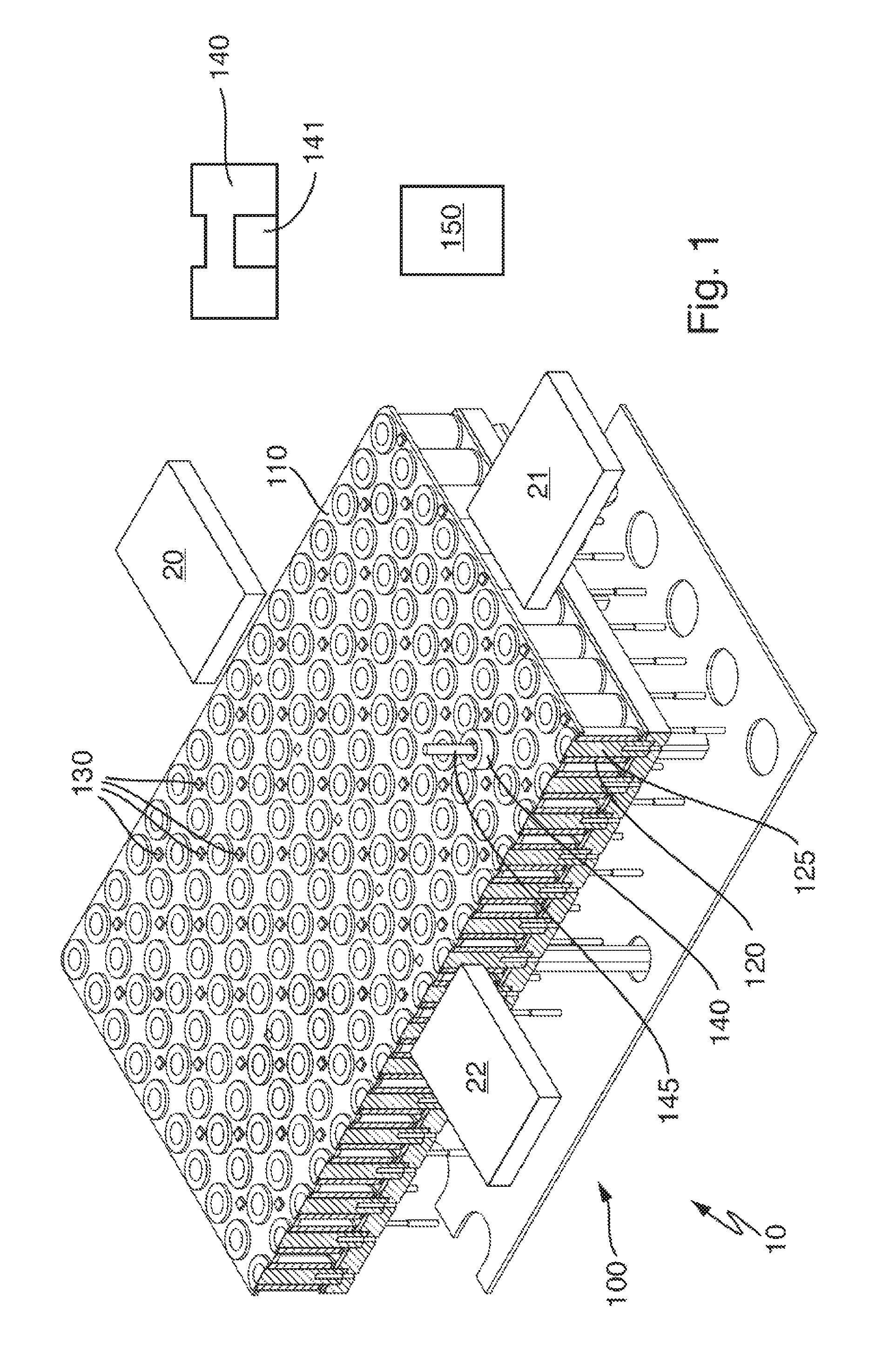
FIG. 1 illustrates schematically a laboratory automation system in a perspective view according to an embodiment of the present disclosure.
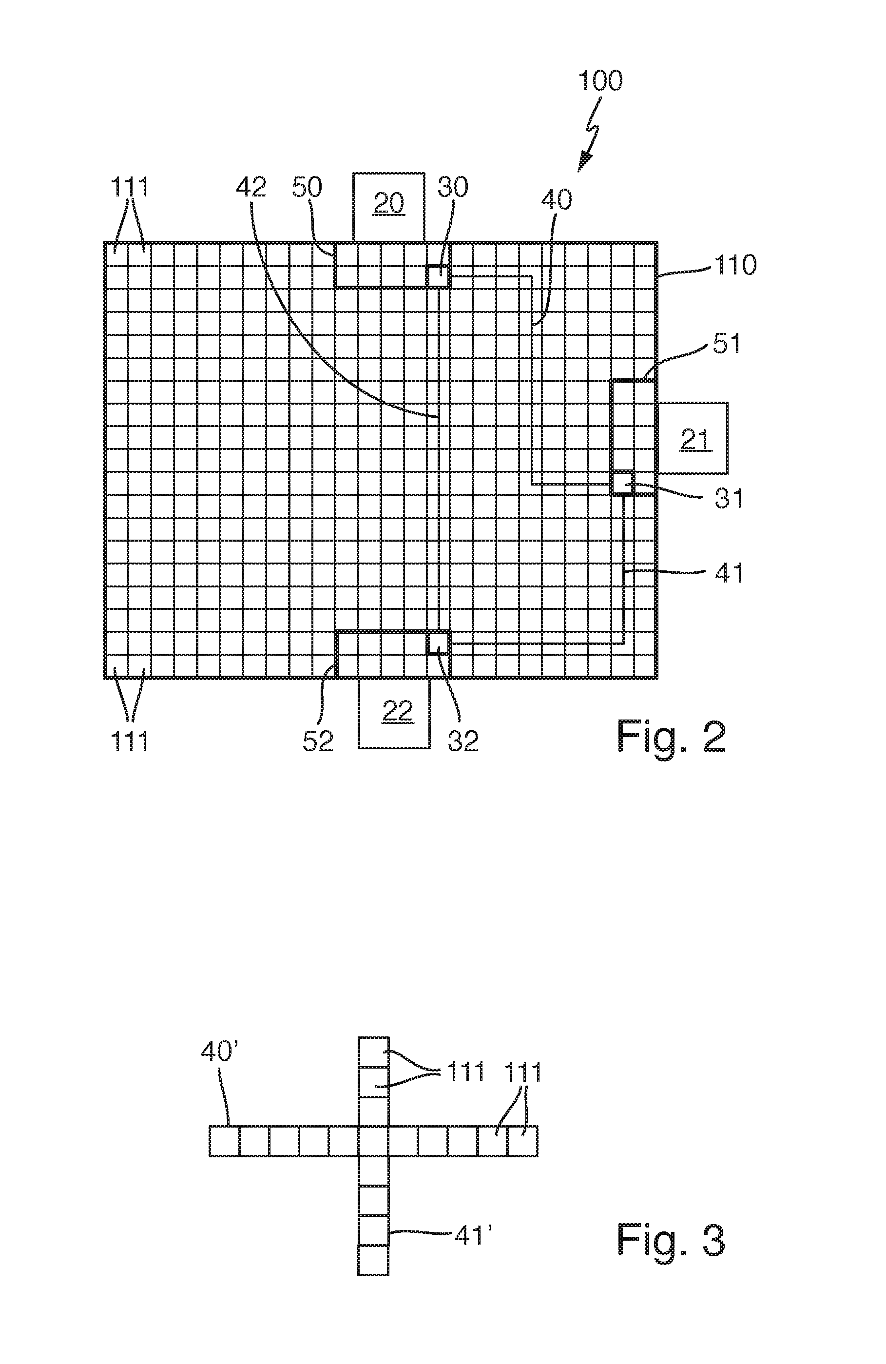
FIG. 2 illustrates schematically the laboratory automation system of FIG. 1 in a top view according to an embodiment of the present disclosure.
FIG. 3 illustrates shows different pre-calculated routes comprising reserved fields according to an embodiment of the present disclosure.
DETAILED DESCRIPTION
In the following detailed description of the embodiments, reference is made to the accompanying drawings that form a part hereof, and in which are shown by way of illustration, and not by way of limitation, specific embodiments in which the disclosure may be practiced. It is to be understood that other embodiments may be utilized and that logical, mechanical and electrical changes may be made without departing from the spirit and scope of the present disclosure.
The method can be adapted to operate a laboratory sample distribution system. The laboratory sample distribution system can comprises a number (e.g., 10 to 10000) of sample container carriers. The sample container carriers can be respectively adapted to carry one or more sample containers. The sample containers can respectively comprise samples to be analyzed by a plurality (e.g., 2 to 50) of laboratory stations.
The laboratory sample distribution system can further comprise a, substantially planar, transport plane. The transport plane can be adapted to support the sample container carriers, i.e. the sample container carriers can be placed on top of the transport plane and can be moved on top of and over the transport plane.
The transport plane can comprise a plurality (e.g., 2 to 100) of transfer locations, or nodes. The transfer locations, or nodes, can be assigned to corresponding laboratory stations. For example, each laboratory station may have a single corresponding transfer location, or node. Alternatively, more than one transfer location, or node, may be assigned to a corresponding laboratory station. The transfer locations, or nodes, may be statically, or dynamically, assigned to the laboratory stations. In other words, during operation, the transfer locations may be changed, if necessary.
The laboratory sample distribution system can further comprise a drive. The drive can be adapted to move the sample container carriers on and over the transport plane.
The operating method can comprise, during an initialization (i.e., starting and/or booting) of the laboratory sample distribution system e.g., fixed routes extending over the transport plane can be pre-calculated depending on, e.g., between, the different transfer locations. In other words, the pre-calculated routes can be provided on the transport plane between the transfer locations. The transfer locations may represent initial, or goal, nodes in the sense of Graph theory.
After the initialization of the laboratory sample distribution system during a normal operational mode, the drive can be controlled such that the sample container carriers can move along the pre-calculated routes over the transport plane, if and when the sample container carriers are to be distributed between the different laboratory stations. In other words, after the initialization of the laboratory sample distribution system during a normal operational mode, the drive can be controlled such that the sample container carriers can repeatedly move, for example, only, along the pre-calculated fixed routes over the transport plane, if and when the sample container carriers are to be distributed between the different laboratory stations. The term "fixed" can denote that the routes can be statically calculated (i.e. not recalculated) and that the calculated routes can be used by several sample container carriers and may not be calculated for each sample container carrier individually. Self-evidently, in specific use scenarios, the sample container carriers may move apart from the pre-calculated routes, e.g., in case the sample container carriers have to be removed from the transport plane and/or in error conditions. Further, empty sample container carriers may move along different routes and/or apart from the pre-calculated routes.
The routes can be calculated using an informed search algorithm such as, for example, an A*-algorithm or a D*-algorithm. The A*-algorithm is an algorithm that can be used in path finding and graph traversal to efficiently calculate a traversable path between different nodes, e.g., in the form of the transfer locations. The A*-algorithm uses a best-first search and can find a least-cost path from a given initial node to one goal node (out of one or more possible goals). As the A*-algorithm traverses the graph, it can follow a path of the lowest expected total cost or distance, keeping a sorted priority queue of alternate path segments along the way. The D*-algorithm is a refined A*-algorithm.
The routes can be calculated such that a number of intersections between different routes can be minimized.
During the initialization of the laboratory sample distribution system, respective buffer areas located on the transport plane can be logically allocated to the laboratory stations. Samples waiting to be analyzed by the laboratory stations can be buffered in the buffer areas. For example, each laboratory station may have a single corresponding buffer area on the transport plane. Alternatively, more than one buffer area may be assigned to a corresponding laboratory station on the transport plane. The buffer areas can be allocated such that the pre-calculated routes do not intersect the buffer areas.
The sample container carriers can be entered into the buffer areas or can be removed from the buffer areas exclusively over (passing) the transfer locations, i.e., the transfer locations can serve as a gate (entrance/exit) to the buffer areas.
The transport plane can be segmented into logical fields, e.g., square shaped logical fields of substantially identical size and outline. The logical fields can be arranged in a chess board manner. In a time-prioritized reservation scheme, an adjustable number (e.g., 1 to 100) of logical fields positioned on or lying on a pre-calculated route can respectively be reserved for sample container carriers to be moved. In other words, the logical fields can be reserved in a first come, first serve manner for each sample container carrier to be moved. The logical fields can typically be reserved before starting a movement of a sample container carrier. Nevertheless, the logical fields can be reserved during a movement of a sample container carrier, if the sample container carrier has not yet reached the logical fields to be reserved. A sample container carrier moving on a route comprising logical fields being reserved for another sample container carrier with a higher time priority, i.e., the logical fields have been reserved for the other sample container carrier prior to the reservation for the moving sample container, can be stopped before the reserved field or may not be started. The reserved fields can be released when the sample container carrier has passed the reserved field(s).
After the initialization of the laboratory sample distribution system, operating data of the laboratory sample distribution system can be collected and stored. During a next initialization of the laboratory sample distribution system, the routes can be pre-calculated depending on the transfer locations and depending on the operating data.
The operating data can comprise information regarding a volume of traffic on the routes. The information regarding the volume of traffic can comprise information of the number of sample container carriers being moved on the route per time unit (e.g., per minute/hour/day etc.). A time profile of the volume of traffic over the operating time may be determined.
The step of pre-calculating the routes can comprise that a number of lanes assigned to the routes can be determined depending on the volume of traffic. For example, in case of low volume of traffic, a single lane may be assigned to a route. In case of increasing volume of traffic, two or more lanes may be assigned to the route. The routes can be, in one embodiment, one-way lanes.
Samples, and/or sample containers, and/or the sample container carriers can be transferred to/from the laboratory stations using the transfer locations. For example, a pick-and-place device can pick a sample container comprised in a sample container carrier located at one of the transfer locations and can transfer the sample container to the laboratory station. Accordingly, a sample container can be transferred from one of the laboratory stations to an empty sample container carrier located on the transfer location.
During the initialization of the laboratory sample distribution system, the routes can be pre-calculated between the transfer locations, i.e., the end points, or end nodes, of the routes can be formed by the transfer locations. If, for example, a first, a second, and a third transfer location are given, a route between the first and the second transfer location, a route between the first and the third transfer location, and a route between the second and the third transfer location can be pre-calculated.
The laboratory sample distribution system can be adapted to perform the method as described above.
The laboratory sample distribution system can comprise a plurality of sample container carriers. The sample container carriers can be adapted to carry one or more sample containers. The sample containers can comprise samples to be analyzed by a plurality of laboratory stations. The system can also comprise a transport plane. The transport plane can be adapted to support the sample container carriers. The transport plane can comprise a plurality of transfer locations The transfer locations can be assigned to corresponding laboratory stations. The system can also comprise a drive. The drive can be adapted to move the sample container carriers on the transport plane. The system can also comprise a control unit such as, for example, in the form of a microprocessor and program storage. The control unit can be adapted to control the laboratory sample distribution system such that the method as described above can be performed. The control unit can be adapted to pre-calculate routes depending on the transfer locations during an initialization of the laboratory sample distribution system and to control the drive such that the sample container carriers can move along the pre-calculated routes after the initialization of the laboratory sample distribution system.
The sample container carriers can comprise at least one magnetically active device such as, for example, at least one permanent magnet. The drive can comprise a plurality of electro-magnetic actuators being stationary arranged in rows and columns below the transport plane. The electro-magnetic actuators can be adapted to apply a magnetic force to the sample container carriers. The control unit can be adapted to activate the electromagnetic actuators such that the sample container carriers can move simultaneously and independently from one another along the pre-calculated routes. The electro-magnetic actuators may define corresponding nodes of a graph in the sense of Graph Theory. A node may be defined or located on the transport plane above the corresponding electro-magnetic actuator. The transfer locations may be formed above a corresponding electro-magnetic actuator. The so defined grid-shaped graph may be used by an informed search algorithm such as, for example, an A*-algorithm or a D*-algorithm, to calculate a traversable path from initial node, or an initial transfer, location to a goal node, or a goal transfer location.
The laboratory automation system comprises a plurality (e.g., 2 to 50) of laboratory stations such as, for example, pre-analytical, analytical and/or post-analytical stations, and a laboratory sample distribution system as described above.
Pre-analytical stations may be adapted to perform any kind of pre-processing of samples, sample containers and/or sample container carriers. Analytical stations may be adapted to use a sample or part of the sample and a reagent to generate a measuring signal, the measuring signal indicating if and in which concentration, if any, an analyte exists. Post-analytical stations may be adapted to perform any kind of post-processing of samples, sample containers and/or sample container carriers.
The pre-analytical, analytical and/or post-analytical stations may comprise at least one of a decapping station, a recapping station, a centrifugation station, an archiving station, a pipetting station, a sorting station, a tube type identification station, and a sample quality determining station.
The pre-calculated routes can be visualized on the transport plane, such that an operator can control the pre-calculated routes and, if necessary, manually adjust the pre-calculated routes. In order to visualize the pre-calculated routes visualizing means e.g., in the form of light emitting devices such as LEDs can be arranged below the transport plane. The transport plane can be at least partially translucent. For example, for each electro-magnetic actuator, a corresponding LED may be provided placed adjacent to the electro-magnetic actuator. The visualizing means may further be used to visualize the operating state of the corresponding electro-magnetic actuator and may, for example, indicate if the corresponding electro-magnetic actuator is defective. Additionally, if the transport plane is segmented into a number of separate modules, defective modules may be signalized by the visualizing means located inside the defective module.
Referring initially to FIG. 1, FIG. 1 schematically shows a laboratory automation system 10 in a perspective view. The laboratory automation system 10 can comprise three laboratory stations 20, 21, 22, e.g., pre-analytical, analytical and/or post-analytical stations, and a laboratory sample distribution system 100. Self-evidently, the laboratory automation system 10 may comprise more than three laboratory stations 20, 21, 22.
The laboratory sample distribution system 100 can comprises a plurality of sample container carriers 140. For the sake of explanation, only a single sample container carrier 140 is depicted. Self-evidently, the laboratory sample distribution system 100 can comprise a plurality of sample container carriers 140, e.g., 50 to 500 sample container carriers 140. The sample container carriers 140 can respectively comprise a magnetically active device 141 in the form of a permanent magnet.
The sample container carriers 140 can be adapted to carry one or more sample containers 145. The sample containers 145 can comprise samples to be analyzed by the laboratory stations 20, 21, 22.
The laboratory sample distribution system 100 can further comprises a transport plane 110. The transport plane 110 can be adapted to support or carry the sample container carriers 140.
Positions sensors 130, e.g., in form of Hall sensors, can be distributed over the transport plane 110, such that a location of a respective sample container carrier 140 can be detected.
Referring to FIG. 2, the transport plane 110 can comprise a plurality of logical transfer locations 30, 31, 32. The transfer location 30 can be logically allocated to the laboratory station 20, the transfer location 31 can be logically allocated to the laboratory station 21 and the transfer location 32 can be logically allocated to the laboratory station 22. The transport plane 110 can comprises a plurality of logical buffer areas 50, 51, 52. The buffer area 50 can be logically allocated to the laboratory station 20, the buffer area 51 can be logically allocated to the laboratory station 21, and the buffer area 52 can be logically allocated to the laboratory station 22. Samples waiting to be analyzed by the laboratory stations 20, 21, 22 can be buffered in the respective buffer areas 50, 51, 52. Sample container carriers 140 can enter the buffer areas 50, 51, 52 or can be removed from the buffer areas 50, 51, 52 exclusively over the corresponding transfer locations 30, 31, 32.
Referring to FIG. 1 again, the laboratory sample distribution system 100 can further comprises a drive. The drive can comprise a plurality of electro-magnetic actuators 120 being stationary arranged in rows and columns below the transport plane 110. The electro-magnetic actuators 120 can respectively comprise a coil surrounding a ferromagnetic core 125. The electro-magnetic actuators 120 can be adapted to apply a magnetic drive force to the container carriers 140.
The laboratory sample distribution system 100 can further comprise a control unit 150. The control unit 150 can, inter alia, control the electro-magnetic actuators 120 such that the sample container carriers 140 may move simultaneously and independently from one another over the transport plane 110.
The method of operation of the laboratory sample distribution system 100 will be described with respect to FIGS. 2 and 3.
FIG. 2 schematically shows the laboratory automation system 10 of FIG. 1 in a top view. During an initialization, or start-up phase, of the laboratory sample distribution system 100, the control unit 150 can pre-calculate routes 40, 41, 42 between the transfer locations 30, 31, 32. In addition, during the initialization of the laboratory sample distribution system 100, the buffer areas 50, 51, 52 can be logically allocated to the laboratory station 20, 21, 22, respectively.
After the initialization of the laboratory sample distribution system 100, the control unit 150 can control the electro-magnetic actuators 120 such that the sample container carriers 140 can move along the pre-calculated routes 40, 41, 42, if the sample container carriers 140 have to be distributed between the laboratory stations 20, 21, 22.
The routes 40, 41, 42 can be calculated using an A*-algorithm. The routes 40, 41, 42 can be, inter alia, calculated such that a number of intersections between different routes 40, 41, 42 can be minimized. In the embodiment depicted, no intersections occur.
Referring to FIGS. 2 and 3, the transport plane 110 can be logically segmented into equally-sized, substantially square shaped logical fields 111. Each logical field 11 can be assigned to, i.e., covers, a corresponding electro-magnetic actuator 120.
FIG. 3 schematically and partially shows different pre-calculated routes 40' and 41' comprising reserved fields 111. The routes 40' and 41', differing from the routes 40 and 41 depicted in FIG. 2, have an intersection.
In a time-prioritized reservation scheme, a plurality of, for example 10, logical fields 111 lying on the routes 40' and 41' can be reserved for sample container carriers to be moved on the routes 40' and 41'. In other words, the logical fields 111 can be reserved in a first come, first serve manner for each sample container 140 carrier to be moved.
Given that for a sample container carrier to be moved on route 40' the logical fields 111 on the route 40' have been reserved before the logical fields 111 on the route 41' have been reserved for another sample container carrier to be moved on route 41', the sample container carrier moving on route 41' can stop before reaching the field in the intersection of the routes 40' and 41', thus avoiding a potential collision. The reserved fields 111 can be released when the sample container carriers have passed the reserved fields 111.
After the initialization of the laboratory sample distribution system 100, operating data of the laboratory sample distribution system 100 can be collected. The operating data can comprise information regarding a volume of traffic on the routes 40, 41, 42. During a next initialization of the laboratory sample distribution system 100, the routes 40, 41, 42 can be pre-calculated additionally depending on the volume of traffic. For example, a number of lanes assigned to the routes 40, 41, 42 can be determined depending on the volume of traffic. As depicted in FIG. 3, respective single lanes of logical fields 111 can be assigned to the routes 40' and 41'. If, for example, the volume of traffic on route 40' would be above a given threshold, a second (third, etc.) lane of logical fields 111 can be assigned to the route 40'.
It is noted that terms like "preferably," "commonly," and "typically" are not utilized herein to limit the scope of the claimed embodiments or to imply that certain features are critical, essential, or even important to the structure or function of the claimed embodiments. Rather, these terms are merely intended to highlight alternative or additional features that may or may not be utilized in a particular embodiment of the present disclosure.
For the purposes of describing and defining the present disclosure, it is noted that the term "substantially" is utilized herein to represent the inherent degree of uncertainty that may be attributed to any quantitative comparison, value, measurement, or other representation. The term "substantially" is also utilized herein to represent the degree by which a quantitative representation may vary from a stated reference without resulting in a change in the basic function of the subject matter at issue.
Having described the present disclosure in detail and by reference to specific embodiments thereof, it will be apparent that modifications and variations are possible without departing from the scope of the disclosure defined in the appended claims. More specifically, although some aspects of the present disclosure are identified herein as preferred or particularly advantageous, it is contemplated that the present disclosure is not necessarily limited to these preferred aspects of the disclosure.
* * * * *
D00000
D00001
D00002
XML
uspto.report is an independent third-party trademark research tool that is not affiliated, endorsed, or sponsored by the United States Patent and Trademark Office (USPTO) or any other governmental organization. The information provided by uspto.report is based on publicly available data at the time of writing and is intended for informational purposes only.
While we strive to provide accurate and up-to-date information, we do not guarantee the accuracy, completeness, reliability, or suitability of the information displayed on this site. The use of this site is at your own risk. Any reliance you place on such information is therefore strictly at your own risk.
All official trademark data, including owner information, should be verified by visiting the official USPTO website at www.uspto.gov. This site is not intended to replace professional legal advice and should not be used as a substitute for consulting with a legal professional who is knowledgeable about trademark law.