Supraventricular tachy sensing vector
Perschbacher , et al. July 16, 2
U.S. patent number 10,350,419 [Application Number 15/265,674] was granted by the patent office on 2019-07-16 for supraventricular tachy sensing vector. This patent grant is currently assigned to Cardiac Pacemakers, Inc.. The grantee listed for this patent is Cardiac Pacemakers, Inc.. Invention is credited to Ron A. Balczewski, James O. Gilkerson, David L. Perschbacher.
| United States Patent | 10,350,419 |
| Perschbacher , et al. | July 16, 2019 |
Supraventricular tachy sensing vector
Abstract
A system includes a pulse generator including a can electrode and a lead couplable to the pulse generator, the lead including a distal coil electrode and a proximal coil electrode, wherein both of the coil electrodes are electrically uncoupled from the can electrode such that a unipolar sensing vector is provided between at least one of the coil electrodes and the can electrode.
| Inventors: | Perschbacher; David L. (Coon Rapids, MN), Gilkerson; James O. (Stillwater, MN), Balczewski; Ron A. (Bloomington, MN) | ||||||||||
|---|---|---|---|---|---|---|---|---|---|---|---|
| Applicant: |
|
||||||||||
| Assignee: | Cardiac Pacemakers, Inc. (St.
Paul, MN) |
||||||||||
| Family ID: | 40404967 | ||||||||||
| Appl. No.: | 15/265,674 | ||||||||||
| Filed: | September 14, 2016 |
Prior Publication Data
| Document Identifier | Publication Date | |
|---|---|---|
| US 20170001020 A1 | Jan 5, 2017 | |
Related U.S. Patent Documents
| Application Number | Filing Date | Patent Number | Issue Date | ||
|---|---|---|---|---|---|
| 12277101 | Nov 24, 2008 | ||||
| 61007635 | Dec 13, 2007 | ||||
| Current U.S. Class: | 1/1 |
| Current CPC Class: | A61N 1/3925 (20130101); A61N 1/36592 (20130101); A61N 1/3622 (20130101); A61N 1/39622 (20170801); A61B 5/04011 (20130101); A61N 1/3702 (20130101); A61B 5/0464 (20130101) |
| Current International Class: | A61B 5/04 (20060101); A61N 1/362 (20060101); A61N 1/37 (20060101); A61N 1/39 (20060101); A61N 1/365 (20060101); A61B 5/0464 (20060101) |
References Cited [Referenced By]
U.S. Patent Documents
| 3857399 | December 1974 | Zacouto |
| 4030510 | June 1977 | Bowers |
| 4059116 | November 1977 | Adams |
| 4163451 | August 1979 | Lesnick et al. |
| 4208008 | June 1980 | Smith |
| RE30387 | August 1980 | Denniston, III et al. |
| 4432360 | February 1984 | Mumford et al. |
| 4485818 | December 1984 | Leckrone et al. |
| 4503857 | March 1985 | Boute et al. |
| 4556063 | December 1985 | Thompson et al. |
| 4562841 | January 1986 | Brockway et al. |
| 4596255 | June 1986 | Snell et al. |
| 4791936 | December 1988 | Snell et al. |
| 4809697 | March 1989 | Causey, III et al. |
| 4830006 | May 1989 | Haluska et al. |
| 4856523 | August 1989 | Sholder et al. |
| 4860749 | August 1989 | Lehmann |
| 4869252 | September 1989 | Gilli |
| 4890617 | January 1990 | Markowitz et al. |
| 4905697 | March 1990 | Heggs et al. |
| 4917115 | April 1990 | Flammang et al. |
| 4920965 | May 1990 | Funke et al. |
| 4928688 | May 1990 | Mower |
| 4932406 | June 1990 | Berkovits |
| 4940054 | July 1990 | Grevis et al. |
| 4941471 | July 1990 | Mehra |
| 4944298 | July 1990 | Sholder |
| 4944928 | July 1990 | Grill et al. |
| 4945909 | August 1990 | Fearnot et al. |
| 4972834 | November 1990 | Begemann et al. |
| 4998974 | March 1991 | Aker |
| 5012814 | May 1991 | Mills et al. |
| 5042480 | August 1991 | Hedin et al. |
| 5077667 | December 1991 | Brown et al. |
| 5085215 | February 1992 | Nappholz et al. |
| 5101824 | April 1992 | Lekholm |
| 5107850 | April 1992 | Olive |
| 5127404 | July 1992 | Wyborny et al. |
| 5129394 | July 1992 | Mehra |
| 5133350 | July 1992 | Duffin |
| 5139020 | August 1992 | Koestner et al. |
| 5144949 | September 1992 | Olson |
| 5156147 | October 1992 | Warren et al. |
| 5156154 | October 1992 | Valenta, Jr. et al. |
| 5176136 | January 1993 | Giele |
| 5179949 | January 1993 | Chirife |
| 5183040 | February 1993 | Nappholz et al. |
| 5184614 | February 1993 | Collins et al. |
| 5188106 | February 1993 | Nappholz et al. |
| 5193535 | March 1993 | Bardy et al. |
| 5193550 | March 1993 | Duffin |
| 5197467 | March 1993 | Steinhaus et al. |
| 5207219 | May 1993 | Adams et al. |
| 5226415 | July 1993 | Girodo et al. |
| 5282836 | February 1994 | Kreyenhagen et al. |
| 5284491 | February 1994 | Sutton et al. |
| 5292339 | March 1994 | Stephens et al. |
| 5292341 | March 1994 | Snell |
| 5311874 | May 1994 | Baumann et al. |
| 5312452 | May 1994 | Salo |
| 5331966 | July 1994 | Bennett et al. |
| 5334220 | August 1994 | Sholder |
| 5340361 | August 1994 | Sholder |
| 5350409 | September 1994 | Stoop et al. |
| 5356425 | October 1994 | Bardy et al. |
| 5360437 | November 1994 | Thompson |
| 5365932 | November 1994 | Greenhut |
| 5372607 | December 1994 | Stone et al. |
| 5379776 | January 1995 | Murphy et al. |
| 5383910 | January 1995 | den Dulk |
| 5387229 | February 1995 | Poore |
| 5391189 | February 1995 | van Krieken et al. |
| 5395373 | March 1995 | Ayers |
| 5395397 | March 1995 | Lindgren et al. |
| 5400796 | March 1995 | Wecke |
| 5411524 | May 1995 | Rahul |
| 5411531 | May 1995 | Hill et al. |
| 5417714 | May 1995 | Levine et al. |
| 5423869 | June 1995 | Poore et al. |
| 5431691 | July 1995 | Snell et al. |
| 5437285 | August 1995 | Verrier et al. |
| 5462060 | October 1995 | Jacobson et al. |
| 5474574 | December 1995 | Payne et al. |
| 5480413 | January 1996 | Greenhut et al. |
| 5486198 | January 1996 | Ayers et al. |
| 5487752 | January 1996 | Salo et al. |
| 5507782 | April 1996 | Kieval et al. |
| 5507784 | April 1996 | Hill et al. |
| 5514163 | May 1996 | Markowitz et al. |
| 5522850 | June 1996 | Yomtov et al. |
| 5522859 | June 1996 | Stroebel et al. |
| 5523942 | June 1996 | Tyler et al. |
| 5527347 | June 1996 | Shelton et al. |
| 5534016 | July 1996 | Boute |
| 5540232 | July 1996 | Laney et al. |
| 5540727 | July 1996 | Tockman et al. |
| 5545182 | August 1996 | Stotts et al. |
| 5545186 | August 1996 | Olson et al. |
| 5549649 | August 1996 | Florio et al. |
| 5549654 | August 1996 | Powell |
| 5554174 | September 1996 | Causey, III |
| 5560369 | October 1996 | McClure et al. |
| 5560370 | October 1996 | Verrier et al. |
| 5584864 | December 1996 | White |
| 5584867 | December 1996 | Limousin et al. |
| 5591215 | January 1997 | Greenhut et al. |
| 5605159 | February 1997 | Smith et al. |
| 5607460 | March 1997 | Kroll et al. |
| 5613495 | March 1997 | Mills et al. |
| 5620471 | April 1997 | Duncan |
| 5620473 | April 1997 | Poore |
| 5622178 | April 1997 | Gilham |
| 5626620 | May 1997 | Kieval et al. |
| 5626622 | May 1997 | Cooper |
| 5626623 | May 1997 | Kieval et al. |
| 5632267 | May 1997 | Hognelid et al. |
| 5674250 | October 1997 | de Coriolis et al. |
| 5674251 | October 1997 | Combs et al. |
| 5674255 | October 1997 | Walmsley et al. |
| 5676153 | October 1997 | Smith et al. |
| 5683429 | November 1997 | Mehra |
| 5690686 | November 1997 | Min et al. |
| 5690689 | November 1997 | Sholder |
| 5700283 | December 1997 | Salo |
| 5702424 | December 1997 | Legay et al. |
| 5713928 | February 1998 | Bonnet et al. |
| 5713929 | February 1998 | Hess et al. |
| 5713930 | February 1998 | van der Veen et al. |
| 5713932 | February 1998 | Gillberg et al. |
| 5716382 | February 1998 | Snell |
| 5716383 | February 1998 | Kieval et al. |
| 5716384 | February 1998 | Snell |
| 5718235 | February 1998 | Golosarsky et al. |
| 5724985 | March 1998 | Snell et al. |
| 5725559 | March 1998 | Alt et al. |
| 5725561 | March 1998 | Stroebel et al. |
| 5730141 | March 1998 | Fain et al. |
| 5730142 | March 1998 | Sun et al. |
| 5738096 | April 1998 | Ben-Haim |
| 5741304 | April 1998 | Patwardhan et al. |
| 5741308 | April 1998 | Sholder |
| 5749901 | May 1998 | Bush et al. |
| 5749906 | May 1998 | Kieval et al. |
| 5755736 | May 1998 | Gillberg et al. |
| 5755737 | May 1998 | Prieve et al. |
| 5755739 | May 1998 | Sun et al. |
| 5755740 | May 1998 | Nappholz |
| 5759196 | June 1998 | Hess et al. |
| 5776164 | July 1998 | Ripart |
| 5776167 | July 1998 | Levine et al. |
| 5782887 | July 1998 | van Krieken et al. |
| 5782888 | July 1998 | Sun et al. |
| 5788717 | August 1998 | Mann et al. |
| 5792193 | August 1998 | Stoop |
| 5792200 | August 1998 | Brewer |
| 5800464 | September 1998 | Kieval |
| 5800471 | September 1998 | Baumann |
| 5814077 | September 1998 | Sholder et al. |
| 5814081 | September 1998 | Ayers et al. |
| 5814085 | September 1998 | Hill |
| 5836975 | November 1998 | DeGroot |
| 5836987 | November 1998 | Baumann et al. |
| 5840079 | November 1998 | Warman et al. |
| 5842997 | December 1998 | Verrier et al. |
| 5846263 | December 1998 | Peterson et al. |
| 5853426 | December 1998 | Shieh |
| 5855593 | January 1999 | Olson et al. |
| 5861007 | January 1999 | Hess et al. |
| 5865838 | February 1999 | Obel et al. |
| 5871507 | February 1999 | Obel et al. |
| 5873895 | February 1999 | Sholder et al. |
| 5873897 | February 1999 | Armstrong et al. |
| 5876422 | March 1999 | Van Groeningen |
| 5891178 | April 1999 | Mann et al. |
| 5893882 | April 1999 | Peterson et al. |
| 5897575 | April 1999 | Wickham |
| 5902324 | May 1999 | Thompson et al. |
| 5928271 | July 1999 | Hess et al. |
| 5931856 | August 1999 | Bouhour et al. |
| 5931857 | August 1999 | Prieve et al. |
| 5935081 | August 1999 | Kadhiresan |
| 5944744 | August 1999 | Paul et al. |
| 5951592 | September 1999 | Murphy |
| 5968079 | October 1999 | Warman et al. |
| 5968081 | October 1999 | Levine |
| 5974341 | October 1999 | Er et al. |
| 5978707 | November 1999 | Krig et al. |
| 5978710 | November 1999 | Prutchi et al. |
| 5983138 | November 1999 | Kramer |
| 5987354 | November 1999 | Cooper et al. |
| 5987356 | November 1999 | DeGroot |
| 5991656 | November 1999 | Olson et al. |
| 5991657 | November 1999 | Kim |
| 5991662 | November 1999 | Kim et al. |
| 5999850 | December 1999 | Dawson et al. |
| 5999854 | December 1999 | Deno et al. |
| 6026320 | February 2000 | Carlson et al. |
| 6041251 | March 2000 | Kim et al. |
| 6044298 | March 2000 | Salo et al. |
| 6047210 | April 2000 | Kim et al. |
| 6049735 | April 2000 | Hartley et al. |
| 6052617 | April 2000 | Kim |
| 6052620 | April 2000 | Gillberg et al. |
| 6058328 | May 2000 | Levine et al. |
| 6070101 | May 2000 | Struble et al. |
| 6081745 | June 2000 | Mehra |
| 6081746 | June 2000 | Pendekanti et al. |
| 6081747 | June 2000 | Levine et al. |
| 6081748 | June 2000 | Struble et al. |
| RE36765 | July 2000 | Mehra |
| 6085116 | July 2000 | Pendekanti et al. |
| 6088618 | July 2000 | Kerver |
| 6091988 | July 2000 | Warman et al. |
| 6096064 | August 2000 | Routh |
| 6122545 | September 2000 | Struble et al. |
| 6128529 | October 2000 | Elser |
| 6129745 | October 2000 | Sun et al. |
| 6134469 | October 2000 | Wietholt |
| 6151524 | November 2000 | Krig et al. |
| 6219579 | April 2001 | Bakels et al. |
| 6223072 | April 2001 | Mika et al. |
| 6223079 | April 2001 | Bakels et al. |
| 6223082 | April 2001 | Bakels et al. |
| 6238420 | May 2001 | Bakels et al. |
| 6246909 | June 2001 | Ekwall |
| 6249699 | June 2001 | Kim |
| 6256534 | July 2001 | Dahl |
| 6263242 | July 2001 | Mika et al. |
| 6266554 | July 2001 | Hsu et al. |
| 6272380 | August 2001 | Warman et al. |
| 6275734 | August 2001 | McClure et al. |
| 6280391 | August 2001 | Olson et al. |
| 6285907 | September 2001 | Kramer et al. |
| 6292693 | September 2001 | Darvish et al. |
| 6317632 | November 2001 | Krig et al. |
| 6324425 | November 2001 | Blow |
| 6351669 | February 2002 | Hartley et al. |
| 6353759 | March 2002 | Hartley et al. |
| 6353761 | May 2002 | Conley et al. |
| 6408209 | June 2002 | Bouhour et al. |
| 6411847 | June 2002 | Mower |
| 6411848 | June 2002 | Kramer et al. |
| 6421564 | July 2002 | Yerich et al. |
| 6424865 | July 2002 | Ding |
| 6430438 | August 2002 | Chen et al. |
| 6430439 | August 2002 | Wentkowski et al. |
| 6434424 | August 2002 | Igel et al. |
| 6438410 | August 2002 | Hsu et al. |
| 6438421 | August 2002 | Stahmann et al. |
| 6501987 | December 2002 | Lovett et al. |
| 6501988 | December 2002 | Kramer et al. |
| 6512951 | January 2003 | Marcovecchio et al. |
| 6522925 | February 2003 | Gilkerson et al. |
| RE38119 | May 2003 | Mower |
| 6687541 | February 2004 | Marcovecchio et al. |
| 6760615 | July 2004 | Ferek-Petric |
| 6763267 | July 2004 | Ding |
| 6847842 | January 2005 | Rodenhiser et al. |
| 6957100 | October 2005 | Vanderlinde et al. |
| 7013176 | March 2006 | Ding et al. |
| 7069077 | June 2006 | Lovett et al. |
| 7120490 | October 2006 | Chen et al. |
| 7123960 | October 2006 | Ding et al. |
| 7142915 | November 2006 | Kramer et al. |
| 7142918 | November 2006 | Stahmann et al. |
| 7184834 | February 2007 | Levine |
| 7203540 | April 2007 | Ding et al. |
| 7266411 | September 2007 | Paris et al. |
| 7283872 | October 2007 | Boute et al. |
| 7308310 | December 2007 | Levine et al. |
| 7460908 | December 2008 | Krig et al. |
| 2002/0062139 | May 2002 | Ding |
| 2002/0082509 | June 2002 | Vanderlinde et al. |
| 2002/0082660 | June 2002 | Stahmann et al. |
| 2002/0087198 | July 2002 | Kramer et al. |
| 2002/0091415 | July 2002 | Lovett et al. |
| 2002/0120298 | August 2002 | Kramer et al. |
| 2003/0004551 | January 2003 | Chen et al. |
| 2003/0069610 | April 2003 | Kramer et al. |
| 2003/0078630 | April 2003 | Lovett et al. |
| 2003/0083587 | May 2003 | Ferek-Petric |
| 2003/0105491 | June 2003 | Gilkerson et al. |
| 2003/0204214 | October 2003 | Ferek-Patric |
| 2003/0233131 | December 2003 | Kramer et al. |
| 2004/0010295 | January 2004 | Kramer et al. |
| 2004/0077963 | April 2004 | Perschbacher et al. |
| 2004/0172076 | September 2004 | Stahmann et al. |
| 2004/0215249 | October 2004 | Corbucci |
| 2004/0215259 | October 2004 | Krig et al. |
| 2004/0243188 | December 2004 | Vanderlinde et al. |
| 2004/0254613 | December 2004 | Ostroff |
| 2005/0038480 | February 2005 | Ding |
| 2005/0192506 | September 2005 | Kim |
| 2005/0283196 | December 2005 | Bocek et al. |
| 2005/0288719 | December 2005 | Zhang et al. |
| 2006/0111747 | May 2006 | Cazares et al. |
| 2006/0116594 | June 2006 | Zhang et al. |
| 2006/0219252 | June 2006 | Bardy et al. |
| 2006/0167508 | July 2006 | Boute et al. |
| 2006/0195150 | August 2006 | Lovett |
| 2006/0195151 | August 2006 | Vanderlinde et al. |
| 2009/0149904 | June 2009 | Perschbacher et al. |
| 2009/0149907 | June 2009 | Perschbacher et al. |
| 2009/0157133 | June 2009 | Perschbacher et al. |
| 0033418 | Aug 1981 | EP | |||
| 0360412 | Mar 1990 | EP | |||
| 0401962 | Dec 1990 | EP | |||
| 0597459 | May 1994 | EP | |||
| 0617980 | Oct 1994 | EP | |||
| 0674917 | Oct 1995 | EP | |||
| 0748638 | Dec 1996 | EP | |||
| 2007513708 | May 2007 | JP | |||
| 2007517549 | Jul 2007 | JP | |||
| WO-9302746 | Feb 1993 | WO | |||
| WO-9509029 | Apr 1995 | WO | |||
| WO-9711745 | Apr 1997 | WO | |||
| WO-9739798 | Oct 1997 | WO | |||
| WO-9848891 | Nov 1998 | WO | |||
| WO-0004950 | Feb 2000 | WO | |||
| WO-0038782 | Jul 2000 | WO | |||
| WO-0047277 | Aug 2000 | WO | |||
| WO-0071200 | Nov 2000 | WO | |||
| WO-0071202 | Nov 2000 | WO | |||
| WO-0071203 | Nov 2000 | WO | |||
| WO-02045797 | Jun 2002 | WO | |||
| WO-2005058412 | Jun 2005 | WO | |||
| WO-09075725 | Jun 2009 | WO | |||
| WO-09075749 | Jun 2009 | WO | |||
Other References
|
"", Metrix Model 3020 Implantable Atrial Defibrillator, Physician's Manual, InControl, Inc., Redmond, WA, (1998), pp. 4-24-4-27. cited by applicant . "U.S. Appl. No. 09/316,588, Non Final Office Action dated Nov. 21, 2000", 4 pgs. cited by applicant . "U.S. Appl. No. 09/316,588, Notice of Allowance dated Mar. 19, 2001", 6 pgs. cited by applicant . "U.S. Appl. No. 09/316,588, Response filed Feb. 21, 2001 to Non Final Office Action dated Nov. 21, 2000", 10 pgs. cited by applicant . "U.S. Appl. No. 09/837,019, Non Final Office Action dated Aug. 1, 2001", 5 pgs. cited by applicant . "U.S. Appl. No. 09/837,019, Notice of Allowance dated Feb. 8, 2002", 3 pgs. cited by applicant . "U.S. Appl. No. 10/852,602, Corrected Notice of Allowance dated Aug. 4, 2008", 4 pgs. cited by applicant . "U.S. Appl. No. 10/852,602, Notice Of Allowance dated Jul. 11, 2007", 9 pgs. cited by applicant . "U.S. Appl. No. 11/380,148, Restriction Requirement dated Oct. 29, 2008", 7 pgs. cited by applicant . "U.S. Appl. No. 12/277,101, Appeal Brief filed Mar. 26, 2014", 11 pgs. cited by applicant . "U.S. Appl. No. 12/277,101, Appeal Decision mailed Jul. 15, 2016", 6 pgs. cited by applicant . "U.S. Appl. No. 12/277,101, Final Office Action dated Aug. 15, 2013", 8 pgs. cited by applicant . "U.S. Appl. No. 12/277,101, Final Office Action dated Oct. 1, 2012", 7 pgs. cited by applicant . "U.S. Appl. No. 12/277,101, Final Office Action dated Nov. 8, 2011", 10 pgs. cited by applicant . "U.S. Appl. No. 12/277,101, Non Final Office Action dated Mar. 7, 2013", 8 pgs. cited by applicant . "U.S. Appl. No. 12/277,101, Non Final Office Action dated Mar. 28, 2012", 7 pgs. cited by applicant . "U.S. Appl. No. 12/277,101, Non Final Office Action dated Jun. 29, 2011", 9 pgs. cited by applicant . "U.S. Appl. No. 12/277,101, Response filed Feb. 8, 2012 to Final Office Action dated Nov. 8, 2011", 8 pgs. cited by applicant . "U.S. Appl. No. 12/277,101, Response filed Mar. 1, 2013 to Final Office Action dated Oct. 1, 2012", 8 pgs. cited by applicant . "U.S. Appl. No. 12/277,101, Response filed Jun. 7, 2013 to Non Final Office Action dated Mar. 7, 2013", 7 pgs. cited by applicant . "U.S. Appl. No. 12/277,101, Response filed Aug. 8, 2012 to Non Final Office Action dated Mar. 28, 2012", 11 pgs. cited by applicant . "U.S. Appl. No. 12/277,101, Response filed Oct. 27, 2011 to Non Final Office Action dated Jun. 29, 2011", 8 pgs. cited by applicant . "U.S. Appl. No. 12/327,567, Non-Final Office Action dated Sep. 22, 2010", 8 pgs. cited by applicant . "French CNH Equipment Approvals", Clinica, 417, p. 9, (Sep. 5, 1990), 3 pgs. cited by applicant . "International Application Serial No. PCT/US2008/013069, International Search Report dated Mar. 27, 2009", 5 pgs. cited by applicant . "International Application Serial No. PCT/US2008/013305, Search Report dated Mar. 18, 2009", 8 pgs. cited by applicant . "International Application Serial No. PCT/US2008/013305, Written Opinion dated Mar. 18, 2009", 8 pgs. cited by applicant . "International Application Serial No. PCT/US2008/013960, Written Opinion dated Mar. 27, 2009", 8 pgs. cited by applicant . "Japanease Application Serial No. 2010-537922, Office Action dated Jul. 3, 2012", With English Translation, 7 pgs. cited by applicant . "Japanese Application Serial No. 2010-537922, Office Action dated Dec. 18, 2012", With English Translation, 7 pgs. cited by applicant . "Japanese Application Serial No. 2010-537922, Response filed Sep. 26, 2012 to Office Action dated Jul. 3, 2012", With English Claims, 7 pgs. cited by applicant . "Pacemaker System Guide", (c) 2001 Guidant Corporation, 240 pgs. cited by applicant . "Pacemaker System Guide for Pulsar Max II; Mulitprogrammable Pacemakers", Product brochure published by Guidant Corporation, (Apr. 18, 1999), pp. 6-48 and 6-49. cited by applicant . "Pacemaker System Guide for Pulsar Max II; Multiprogrammable Pacemakers", Product brochure published by Guidant Corporation, (Apr. 18, 1999), p. 6-39-6-51. cited by applicant . "Rate-Adaptive Devices Impact Pacemaker Market", Clinica, 467, p. 16, (Sep. 11, 1991), 6 pgs. cited by applicant . "Vitatron Medical Harmony Automatic Dual Chamber Pacemaker Product Information and Programming Guide", Viatron Medical, 22 p., (Date Unknown), Harmony Dual Chamber mentioned in publication Clinica, 467, p. 16, Sep. 11, 1991, "Rate Devices Impact Pacemaker Market", also mentioned in Clinica, 417, p. 9, Sep. 5, 1990 "French CNH Equipment Approvals"., Product Brochure published by Vitatron Medical, 22 pgs. cited by applicant . Ayers, Gregory M., et al., "Ventricular Proarrhythmic Effects of Ventricular Cycle Length and Shock Strength in a Sheep Model of Transvenous Atrial Defibrillation", Circulation, 89 (1), (Jan. 1994), 413-422. cited by applicant . Blommaert, D., et al., "Effective Prevention of Atrial Fibrillation by Continuous Atrial Overdrive Pacing After Coronary Artery Bypass Surgery", JACC, vol. 35, No. 6, (May 2000), 1411-1415 pgs. cited by applicant . Buhr, T. A., et al., "Novel Pacemaker Algorithm Diminishes Short-Coupled Ventricular Beats In Atrial Fibrillation", Pacing and Clinical Electrophysiology, vol. 24, Part II, (Abstract Only), (Apr. 2001), 729 pgs. cited by applicant . Campbell, R. M., et al., "Atrial Overdrive Pacing for Conversion of Atrial Flutter in Children", Pediatrics, 75(4), (Apr. 1985), 730-736. cited by applicant . Clark, David M., et al., "Hemodynamic Effects of an Irregular Sequence of Ventricular Cycle Lengths During Atrial Fibrillation", JACC, vol. 30, No. 4, (Oct. 1997), 1039-1045. cited by applicant . Cohen, R. J., et al., "Quantitative Model for Ventricular Response During Atrial Fibrillation", IEEE Transactions on Biomedical Engineering, 30, (1983), 769-782. cited by applicant . Duckers, H. J., et al., "Effective use of a novel rate-smoothing algorithm in atrial fibrillation by ventricular pacing", European Heart Journal, 18, (1997), 1951-1955 pgs. cited by applicant . Fahy, G. J., et al., "Pacing Strategies to Prevent Atrial Fibrillation", Atrial Fibrillation, 14(4), (Nov. 1996), 591-596. cited by applicant . Fromer, M., et al., "Algorithm for the Prevention of Ventricular Tachycardia Onset: The Prevent Study", The American Journal of Cardiology, 83 (5B), (Mar. 11, 1999), 450-470 pgs. cited by applicant . Garrigue, S., et al., "Prevention of Atrial Arrhythmias during DDD Pacing by Atrial Overdrive", Pacing and Clinical Electrophysiology, 21(9), (Sep. 1998), 1751-1759. cited by applicant . Greenhut, S., et al., "Effectiveness of a Ventricular Rate Stabilization Algorithm During Atrial Fibrillation in Dogs", Pace Abstract, Abstract No. 60, (1996), 1 pg. cited by applicant . Guidant, "CONTAK TR CHFD Model 1241", System Guide, Congestive Heart Failure Device, (1999), 1-191. cited by applicant . Heuer, H., et al., "Dynamic Dual-Chamber Overdrive Pacing with an Implantable Pacemaker System: A New Method for Terminating Slow Ventricular Tachycardia", Zeitschrift fur Kardiologie, 75, German Translation by the Ralph McElroy Translation Company, Austin, TX, (1986), 6 pages. cited by applicant . Heuer, H., et al., "Dynamische Zweikammer-Overdrive-Stimulation mit einem implantierbaren Schrittmachersystem als neue Methode zur Beendigung Langsamer ventrikularer Tachykardien", Z Kardiol; 75, Includes English translation (5 pgs.), (1986), 673-675 pgs. cited by applicant . Jenkins, J., et al., "Diagnosis of Atrial Fibrillation Using Electrogram from Chronic Leads: Evaluation of Computer Algorithm", Pacing and Clinical Electrophysiology, 11(5), (1988), 622-631. cited by applicant . Jung, J., et al., "Discrimination of Sinus Rhythm, Atrial Flutter, and Atrial Fibrillation Using Bipolar Endocardial Signals", Journal of Cardiovascular Electrophysiology, 9 (7), (Jul. 1998), 689-695 pgs. cited by applicant . Krig, D. B, et al., "Method and Apparatus for Treating Irregular Ventricular Contractions Such as During Atrial Arrhythmia", U.S. Appl. No. 09/316,515, filed May 21, 1999, 57 pgs. cited by applicant . Lau, C. P., et al., "A new pacing method for rapid regularization and rate control in atrial fibrillation", Am J Cardiol., 65(18), (May 15, 1990), 1198-203. cited by applicant . Lau, Chu-Pak, et al., "Efficacy of Ventricular Rate Stabilization by Right Ventricular Pacing During Atrial Fibrillation", Pacing and Clinical Electrophysiology, 21(3), (Mar. 1998), 542-548. cited by applicant . Lovett, E. G., "Cardiac Pacing System for Prevention of Ventricular Fibrillation and Ventricular Tachycardia Episodes", U.S. Appl. No. 09/569,295, filed May 13, 2000, 30 pgs. cited by applicant . Medtronic, "Insync III Device Model 8042", Device Programming Guide, Insync III Device Model 8042, Vision Programmer Software Model 9981, (2000), 1-260. cited by applicant . Medtronic, "Insync III Device Model 8042", Device Reference Guide, Insync III Device Model 8042, Vision Programmer Software Model 9981, (2002), 1-252. cited by applicant . Mehra, R., et al., "Prevention of Atrial Fibrillation/Flutter by Pacing Techniques", Interventional Electrophysiology, Second Edition, Chapter 34, Futura Publishing Company, Inc., (1996), 521-540 pgs. cited by applicant . Morris, M. M., et al., "Intracardiac Electrogram Transformation: Morphometric Implications for Implantable Devices", Journal of Electrocardiology, 29 Supplement, (1996), 124-129. cited by applicant . Mower, Morton, "Method and Apparatus for Treating Hemodynamic Disfunction", U.S. Patent Office Patent Application Information Retrieval (PAIR) search results for U.S. Appl. No. 10/214,474, filed Aug. 8, 2002, entitled, 3 pgs. cited by applicant . Murgatroyd, F. D., et al., "A New Pacing Algorithm for Overdrive Suppression of Atrial Fibrillation", Pacing and Clinical Electrophysiology, 17(11 Pt. 2), (Nov. 1994, Part), 1966-1973. cited by applicant . Schuller, H., et al., "Far Field R-Wave Sensing--An Old Problem Repeating", Pacing and Clinical Electrophysiology, 19, Part II, NASPE Abstract No. 264, (1996), p. 631. cited by applicant . Seim, G., et al., "Classification of Atrial Flutter and Atrial Fibrillation Using an Atrial Dispersion Index (ADI)", Guidant CRM Therapy Research Peer Review Report Revision 2.0, (Jan. 6, 1999), 27 pgs. cited by applicant . St. Jude Medical, "Atlas + HF Models V-343, V-341", User's Manual, Implantable Cardioverter-Defibrillator, (Sep. 2003), 1-30. cited by applicant . St. Jude Medical, "Epic HF Model V-339", User's Manual, Implantable Cardioverter-Defibrillator, (Jul. 2002), 1-26. cited by applicant . St. Jude Medical, "Model 3510 Programmer with Model 3307 Software", Reference Manual, For Atlas, Atlas+, Epic, Epic+, Photon u and Photon Implantable Cardioverter/Defibrillators, (Sep. 2003), 1-314. cited by applicant . Stephany, G. R., et al., "Real-Time Estimation of Magnitude-Square Coherence for Use in Implantable Devices", IEEE Computers in Cardiology, (1992), 375-378 pgs. cited by applicant . Sutton, R., "Pacing in Atrial Arrhythmias", Pacing and Clinical Electrophysiology, 13(12), (Dec. 1990, Part), 1823-1827. cited by applicant . Sweeney, M. O., et al., "Adverse Effect of Ventricular Pacing on Heart Failure and Atrial Fibrillation Among Patients With Normal Baseline QRS Duration in a Clinical Trial of Pacemaker Therapy for Sinus Node Dysfunction", Circulation, 107(23), (Jun. 17, 2003), 2932-2937. cited by applicant . Swiryn, S., et al., "Detection of Atrial Fibrillation by Pacemakers and Antiarrhythmic Devices", Nonpharmacological Management of Atrial Fibrillation, Chapter 21, Futura Publishing Co, Inc. Armonk, NY, (1997), 309-318 pgs. cited by applicant . Tse, H. F., et al., "Effects of ventricular rate regularization pacing on quality of life and symptoms in patients with atrial fibrillation (Atrial fibrillation symptoms mediated by pacing to mean rates [AF Symptoms study])", Am J Cardiol., 94(7), (Oct. 2004), 938-41. cited by applicant . Wittkampf, F. H.M ., et al., "Rate Stabilization by Right Ventricular Patching in Patients with Atrial Fibrillation", Pace, 9(6)(Part 2), (Nov.-Dec. 1986), 1147-1153. cited by applicant . Wittkampf, Fred H.M., et al., "Effect of Right Ventricular Pacing on Ventricular Rhythm During Atrial Fibrillation", JACC, vol. 11, No. 3, (Mar. 1988), 539-545. cited by applicant . Zhu, D. W, "Electrophysiology, Pacing and Arrhythmia: Pacing Therapy for Atrial Tachyarrhythmias", Clinical Cardiology, 19(9), (1996), 737-742. cited by applicant . "Japanese Application Serial No. 2010-537922, Response filed Jun. 14, 2013 to Non Final Office Action dated Dec. 18, 2012", With English Claims, 7 pgs. cited by applicant. |
Primary Examiner: Levicky; William J
Attorney, Agent or Firm: Schwegman Lundberg & Woessner, P.A.
Parent Case Text
CLAIM OF PRIORITY
This application is a continuation of U.S. application Ser. No. 12/277,101, filed Nov. 24, 2008, which claims the benefit under 35 U.S.C. 119(e) of U.S. Provisional Application No. 61/007,635, filed on Dec. 13, 2007, each of which is hereby incorporated by reference in its entirety.
Claims
What is claimed is:
1. A method comprising: providing a lead and an associated pulse generator, the pulse generator including a can electrode, the lead including a proximal coil electrode which is electrically isolated from the can electrode, and the lead including a distal coil electrode which is electrically isolated from the can electrode; sensing heart signals using a first unipolar sensing vector between the distal coil electrode and the can electrode and a second unipolar sensing vector between the proximal coil electrode and the can electrode.
2. The method of claim 1, wherein sensing heart signals includes the pulse generator differentiating between SVT signals and VT signals.
3. The method of claim 2, wherein differentiating between SVT signals and VT signals includes using a template of a correlation between shock vector electrograms and RV rate vector electrograms during normal sinus rhythm.
4. The method of claim 3, including detecting an arrhythmia from a heart signal, wherein when the arrhythmia is detected, the template is compared to an on-going rhythm, and when the on-going rhythm matches the existing template, then the pulse generator withholds therapy.
5. The method of claim 1, wherein the lead further includes one or more distal pacing and/or sensing electrodes.
6. The method of claim 1, wherein a third sensing vector is provided between the distal coil electrode and the proximal coil electrode.
7. The method of claim 1, wherein the pulse generator is configured such that a sensed unipolar sensing vector can alternate between the first unipolar sensing vector between the distal coil electrode and the can electrode and the second unipolar sensing vector between the proximal electrode and the can electrode.
8. The method of claim 1, wherein the pulse generator is configured such that a first unipolar sensing vector between the distal coil electrode and the can electrode and a second unipolar sensing vector between the proximal electrode and the can electrode occur simultaneously.
Description
TECHNICAL FIELD
This relates to the field of medical devices, and more specifically to a sensing vector for an implantable device.
BACKGROUND
Pulse generators and leads having electrodes implanted in or about the heart have been used to reverse certain life threatening arrhythmia, or to stimulate contraction of the heart. Electrical energy is applied to the heart via an electrode to return the heart to normal rhythm. Leads are usually positioned on, in, or near the ventricle or the atrium and the lead terminal pins are attached to a pacemaker or defibrillator which is implanted subcutaneously. The pulse generator is configured to utilize the electrodes to receive signals from the heart which can indicate certain cardiac events.
SUMMARY
A system includes a pulse generator including a can electrode and a lead couplable to the pulse generator, the lead including a distal coil electrode and a proximal coil electrode, wherein both of the coil electrodes are electrically uncoupled from the can electrode such that a unipolar sensing vector is provided between at least one of the coil electrodes and the can electrode.
BRIEF DESCRIPTION OF THE DRAWINGS
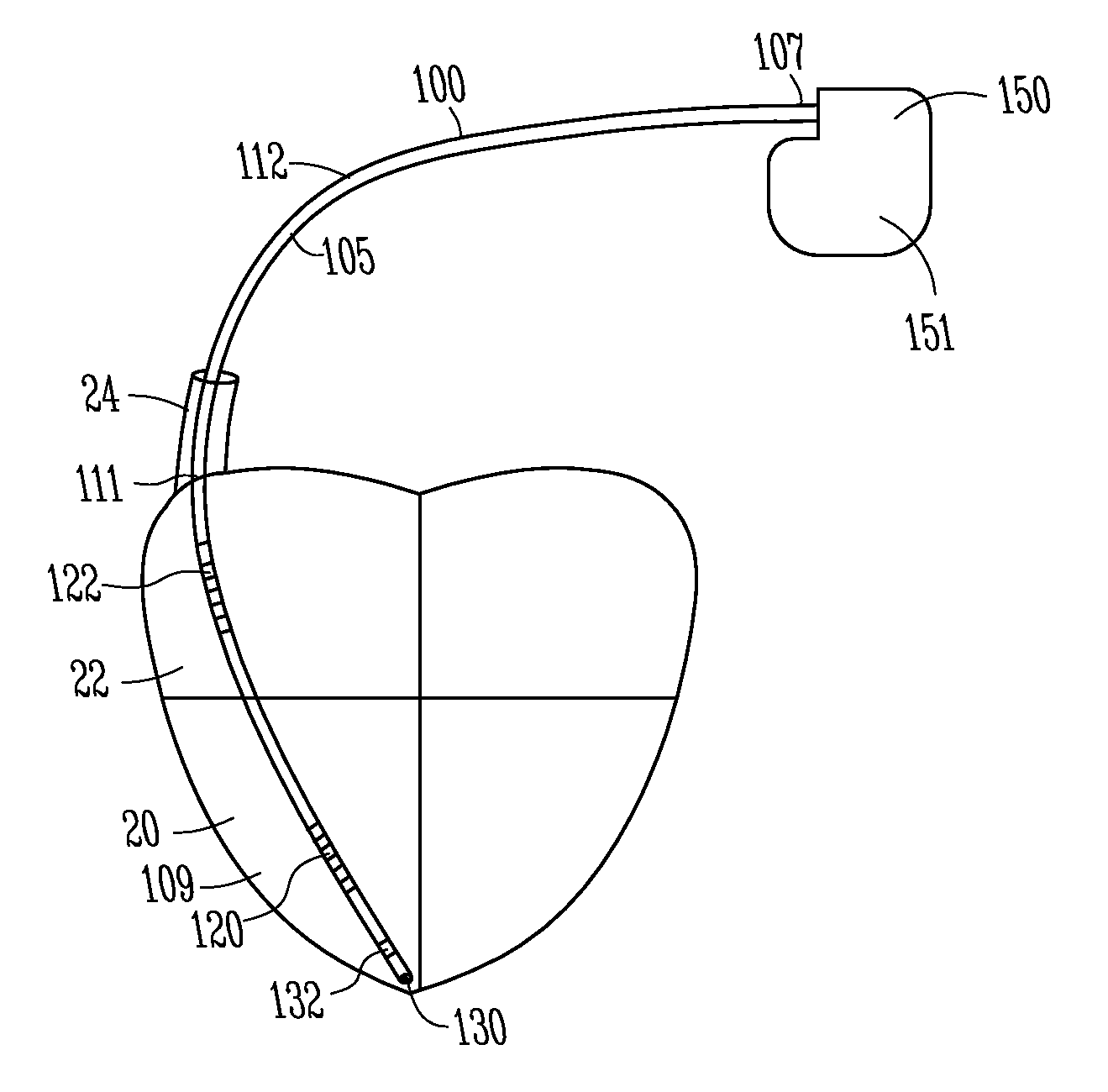
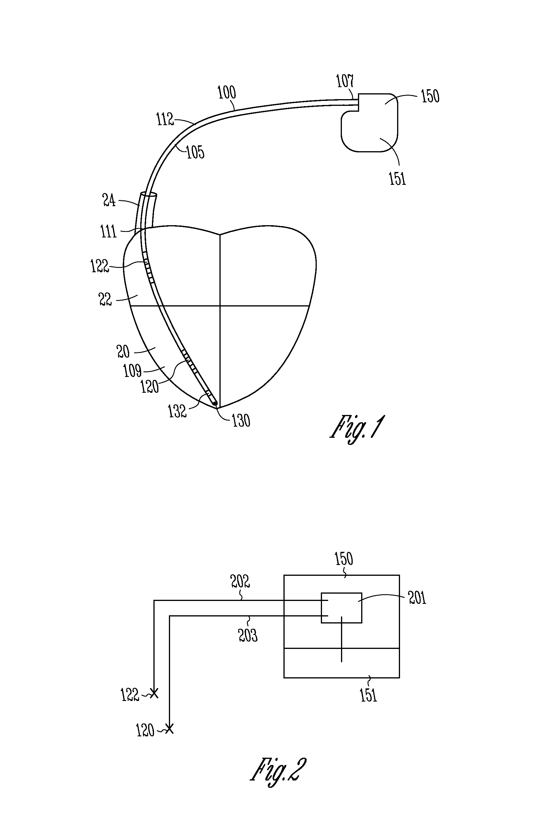
FIG. 1 shows a lead and pulse generator in accordance with one embodiment.
FIG. 2 shows a schematic representation of a lead and pulse generator in accordance with one embodiment.
DETAILED DESCRIPTION
In the following detailed description, reference is made to the accompanying drawings which form a part hereof, and in which is shown by way of illustration specific embodiments in which the invention may be practiced. These embodiments are described in sufficient detail to enable those skilled in the art to practice the invention, and it is to be understood that other embodiments may be utilized and that structural changes may be made without departing from the scope of the present invention. Therefore, the following detailed description is not to be taken in a limiting sense, and the scope of the present invention is defined by the appended claims and their equivalents.
FIG. 1 shows a view of a lead 100 coupled to a pulse generator 150. In one embodiment, lead 100 is adapted to deliver defibrillation shock energy to a heart. Certain embodiments deliver pacing pulses to a heart. Pulse generator 150 can be implanted in a surgically-formed pocket in a patient's chest or other desired location. Pulse generator 150 generally includes electronic components to perform signal analysis, processing, and control. Pulse generator 150 can include a power supply such as a battery, a capacitor, and other components housed in a case or can 151. The device can include microprocessors to provide processing and evaluation to determine and deliver electrical shocks and pulses of different energy levels and timing for ventricular defibrillation, cardioversion, and pacing to a heart in response to cardiac arrhythmia including fibrillation, tachycardia, and bradycardia.
In one embodiment, lead 100 includes a lead body 105 extending from a proximal end 107 to a distal end 109 and having an intermediate portion 111. Lead 100 includes one or more conductors, such as coiled conductors or other conductors, to conduct energy from pulse generator 150 to one or more electrodes, such as a distal defibrillation coil electrode 120 configured to be implanted in right ventricle 20, and a proximal defibrillation coil electrode 122 configured to be implanted in right atrium 22 or superior vena cava 24. The superior vena cava and the right atrium are called the supraventricular portion of the heart. In one embodiment, the lead 100 can include a tip electrode 130 and a distal ring electrode 132 for ventricular sensing and pacing. Some embodiments include one or more proximal ring electrodes for atrial sensing and pacing.
Lead 100 can include lead terminal pins which are attached to pulse generator 150 at a header. The system can include a unipolar system with the housing can 151 acting as an electrode or a bipolar system with a pulse between two electrodes 120, 122, or electrodes 130, 132.
The present system is directed to providing a supraventricular tachycardia sensing vector. The present system provides a technique to better distinguish supraventricular tachycardia (SVT) from ventricular tachycardia (VT). For example, in a past approach, the proximal coil 122 was electrically coupled to can electrode 151 and tachycardia sensing was performed using the distal coil 120 to both the can 151 plus the proximal coil 122. However, this configuration results in difficulties in distinguishing between SVT and VT.
In one embodiment, the present system electrically isolates the can electrode 151 from proximal coil electrode 122 and from the distal coil electrode 120 to provide a supraventricular tachy sensing vector. For example, coil electrode 122 can be electrically isolated from the can electrode 151 and a unipolar sensing vector can be from the proximal coil electrode 122 to the can electrode 151. In one embodiment, a unipolar sensing vector can be from the distal coil 120 to the can electrode 151. In one embodiment, a sensing vector can be from distal coil 120 to proximal electrode 122. These configurations are useful for distinguishing between SVT and VT.
In other embodiments, the present system uncouples the proximal electrode 122 from the can 151 and provides sensing utilizing one or more of electrodes 130, 132.
The term sensing vector is described herein by the location of the two electrodes used by a sensing channel within the pulse generator. The sensing channel uses the electrical signal that exists between the two electrodes to sense cardiac activity. Different sense vectors will present different aspects of the cardiac signal to the sensing channel. In the present embodiments, the sense vectors have improved performance for sensing SVT because these vectors produce a larger SVT to VT signal ratio than in the past.
Thus in various examples, both of the coil electrodes 120, 122 are electrically uncoupled from the can electrode 151 such that a unipolar sensing vector is provided between at least one of the coil electrodes and the can electrode 151. For example, the sensing vector can be provided between the distal electrode 120 and the can electrode 151, or the sensing vector can be provided between the proximal electrode 122 and the can electrode 151. In another example a second sensing vector can be provided between the distal coil electrode 120 and the proximal coil electrode 122.
In another example, the pulse generator can be configured such that the unipolar sensing vector can alternate between the distal coil electrode 120 and the can electrode 151 and the proximal electrode 122 and the can electrode 151. In one embodiment, the pulse generator is configured such that a first unipolar sensing vector between the distal coil electrode 120 and the can electrode 151 and a second unipolar sensing vector between the proximal electrode 122 and the can electrode 151 occur simultaneously.
The pulse generator can be configured to distinguish between VT and SVT using the unipolar sensing vectors discussed above. For example, one technique to distinguish between VT and SVT is to use a template of the correlation between shock vector electrograms and RV rate vector electrograms during normal sinus rhythm. When an arrhythmia is detected, the template is compared to the on-going rhythm; if the rhythm matches the existing template, then it is believed that the origin of the rhythm is supraventricular and the device withholds therapy--the assumption being that a supraventricular rhythm follows the same conduction pathway as normal sinus rhythm, and thus the correlation of the two vectors during SVT would match the normal sinus rhythm template, and therapy can be delivered.
However, if the correlation of the vectors during the rhythm does not match the template, then it is assumed that the rhythm is VT (i.e. the rhythm is not using the normal conduction pathway).
Further embodiments can use a different template created from the new vectors described herein. This new template would provide more power to discriminate problem cases using the template described above--and thus more information from the combination of more vectors would yield more discrimination power.
In one embodiment, electrode 122 is disposed along the lead such that the electrode 122 is configured to be located in the right atrium 22 or superior vena cava 24 after implantation.
FIG. 2 shows a schematic representation of portions of the system described above, in accordance with one embodiment. The lead includes a first conductor 202 coupled between the proximal coil electrode 122 and electronics 201 within the pulse generator 150. The lead also includes a second conductor 203 coupled between distal coil electrode 120 and electronics 201. The can electrode 151 is also coupled to the electronics 201. Electronics 201 includes electrically pathways which provide that the electrodes 122, and 120 are electrically insulated from the can electrode 151. As discussed, the electronics 201 can be configured to allow the various connections to be uncoupled or coupled as desired.
It is understood that the above description is intended to be illustrative, and not restrictive. Many other embodiments will be apparent to those of skill in the art upon reviewing the above description. The scope of the invention should, therefore, be determined with reference to the appended claims, along with the full scope of equivalents to which such claims are entitled.
* * * * *
D00000
D00001
XML
uspto.report is an independent third-party trademark research tool that is not affiliated, endorsed, or sponsored by the United States Patent and Trademark Office (USPTO) or any other governmental organization. The information provided by uspto.report is based on publicly available data at the time of writing and is intended for informational purposes only.
While we strive to provide accurate and up-to-date information, we do not guarantee the accuracy, completeness, reliability, or suitability of the information displayed on this site. The use of this site is at your own risk. Any reliance you place on such information is therefore strictly at your own risk.
All official trademark data, including owner information, should be verified by visiting the official USPTO website at www.uspto.gov. This site is not intended to replace professional legal advice and should not be used as a substitute for consulting with a legal professional who is knowledgeable about trademark law.