Intravascular treatment catheters
Gifford, III , et al. July 16, 2
U.S. patent number 10,350,004 [Application Number 15/212,797] was granted by the patent office on 2019-07-16 for intravascular treatment catheters. This patent grant is currently assigned to Twelve, Inc.. The grantee listed for this patent is Twelve, Inc.. Invention is credited to Stephen Boyd, Mark Deem, Hanson Gifford, III.


View All Diagrams
| United States Patent | 10,350,004 |
| Gifford, III , et al. | July 16, 2019 |
Intravascular treatment catheters
Abstract
The present invention provides devices and methods for decalcifying an aortic valve. The methods and devices of the present invention break up or obliterate calcific deposits in and around the aortic valve through application or removal of heat energy from the calcific deposits.
| Inventors: | Gifford, III; Hanson (Woodside, CA), Deem; Mark (Mountain View, CA), Boyd; Stephen (Murrieta, CA) | ||||||||||
|---|---|---|---|---|---|---|---|---|---|---|---|
| Applicant: |
|
||||||||||
| Assignee: | Twelve, Inc. (Menlo Park,
CA) |
||||||||||
| Family ID: | 36578602 | ||||||||||
| Appl. No.: | 15/212,797 | ||||||||||
| Filed: | July 18, 2016 |
Prior Publication Data
| Document Identifier | Publication Date | |
|---|---|---|
| US 20170014183 A1 | Jan 19, 2017 | |
Related U.S. Patent Documents
| Application Number | Filing Date | Patent Number | Issue Date | ||
|---|---|---|---|---|---|
| 13692613 | Dec 3, 2012 | 9414852 | |||
| 12870270 | Aug 27, 2010 | ||||
| 11299246 | Dec 9, 2005 | 7803168 | |||
| 60698297 | Jul 11, 2005 | ||||
| 60662764 | Mar 16, 2005 | ||||
| 60635275 | Dec 9, 2004 | ||||
| Current U.S. Class: | 1/1 |
| Current CPC Class: | A61B 18/1492 (20130101); A61B 17/2202 (20130101); A61B 17/221 (20130101); A61B 17/22012 (20130101); A61F 2/2445 (20130101); A61B 17/320758 (20130101); A61B 18/02 (20130101); A61M 25/04 (20130101); A61N 7/022 (20130101); A61N 2007/0039 (20130101); A61M 2025/105 (20130101); A61B 2017/22079 (20130101); A61B 2017/22069 (20130101); A61B 2018/00011 (20130101); A61B 18/18 (20130101); A61B 2017/22098 (20130101); A61B 2018/0022 (20130101); A61B 2017/22061 (20130101); A61B 2018/0262 (20130101); A61B 8/12 (20130101); A61B 2017/22038 (20130101); A61B 2017/2215 (20130101) |
| Current International Class: | A61B 8/12 (20060101); A61B 18/02 (20060101); A61B 18/00 (20060101); A61B 17/22 (20060101); A61N 7/02 (20060101); A61N 7/00 (20060101); A61F 2/24 (20060101); A61B 17/221 (20060101); A61B 18/14 (20060101); A61B 18/18 (20060101); A61B 17/3207 (20060101); A61M 25/10 (20130101); A61M 25/04 (20060101) |
References Cited [Referenced By]
U.S. Patent Documents
| 931795 | August 1909 | James |
| 3526219 | September 1970 | Lewis |
| 3565062 | February 1971 | Kuris |
| 3589363 | June 1971 | Banko et al. |
| 3667474 | June 1972 | Lapkin et al. |
| 3752162 | August 1973 | Newash |
| 3823717 | July 1974 | Pohlman et al. |
| 3861391 | January 1975 | Antonevich et al. |
| 3896811 | July 1975 | Storz |
| 4042979 | August 1977 | Angell |
| 4046150 | September 1977 | Schwartz et al. |
| 4188952 | February 1980 | Loschilov et al. |
| 4431006 | February 1984 | Trimmer et al. |
| 4445509 | May 1984 | Auth |
| 4484579 | November 1984 | Meno et al. |
| 4587958 | May 1986 | Noguchi et al. |
| 4589419 | May 1986 | Laughlin et al. |
| 4646736 | March 1987 | Auth |
| 4692139 | September 1987 | Stiles |
| 4709698 | December 1987 | Johnston et al. |
| 4747821 | May 1988 | Kensey et al. |
| 4750902 | June 1988 | Wuchinich et al. |
| 4777951 | October 1988 | Cribier et al. |
| 4787388 | November 1988 | Hofmann |
| 4790812 | December 1988 | Hawkins, Jr. et al. |
| 4796629 | January 1989 | Grayzel |
| 4808153 | February 1989 | Parisi |
| 4819751 | April 1989 | Shimada et al. |
| 4824436 | April 1989 | Wolinsky |
| 4841977 | June 1989 | Griffith et al. |
| 4870953 | October 1989 | DonMicheal et al. |
| 4878495 | November 1989 | Grayzel |
| 4898575 | February 1990 | Fischell et al. |
| 4909252 | March 1990 | Goldberger |
| 4919133 | April 1990 | Chiang |
| 4920954 | May 1990 | Alliger et al. |
| 4936281 | June 1990 | Stasz |
| 4960411 | October 1990 | Buchbinder |
| 4986830 | January 1991 | Owens et al. |
| 4990134 | February 1991 | Auth |
| 5058570 | October 1991 | Idemoto et al. |
| 5069664 | December 1991 | Guess et al. |
| 5071424 | December 1991 | Reger |
| 5076276 | December 1991 | Sakurai et al. |
| 5078717 | January 1992 | Parins et al. |
| 5087244 | February 1992 | Wolinsky et al. |
| 5102402 | April 1992 | Dror et al. |
| 5106302 | April 1992 | Farzin-Nia et al. |
| 5156610 | October 1992 | Reger |
| 5158564 | October 1992 | Schnepp-Pesch et al. |
| 5190540 | March 1993 | Lee |
| 5211651 | May 1993 | Reger et al. |
| 5248296 | September 1993 | Alliger |
| 5255679 | October 1993 | Imran |
| 5267954 | December 1993 | Nita |
| 5269291 | December 1993 | Carter |
| 5282484 | February 1994 | Reger |
| 5295958 | March 1994 | Shturman |
| 5304115 | April 1994 | Pflueger et al. |
| 5304120 | April 1994 | Crandell et al. |
| 5306250 | April 1994 | March et al. |
| 5314407 | May 1994 | Auth et al. |
| 5318014 | June 1994 | Carter |
| 5326341 | July 1994 | Lew et al. |
| 5344395 | September 1994 | Whalen et al. |
| 5345936 | September 1994 | Pomeranz et al. |
| 5356418 | October 1994 | Shturman |
| 5397293 | March 1995 | Alliger et al. |
| 5411025 | May 1995 | Webster, Jr. |
| 5419767 | May 1995 | Eggers et al. |
| 5419777 | May 1995 | Hofling |
| 5443446 | August 1995 | Shturman |
| 5464395 | November 1995 | Faxon et al. |
| 5465717 | November 1995 | Imran et al. |
| 5471982 | December 1995 | Edwards et al. |
| 5476495 | December 1995 | Kordis et al. |
| 5489297 | February 1996 | Duran |
| 5496311 | March 1996 | Abele et al. |
| 5538504 | July 1996 | Linden et al. |
| 5540679 | July 1996 | Fram et al. |
| 5571122 | November 1996 | Kelly et al. |
| 5584879 | December 1996 | Reimold et al. |
| 5588960 | December 1996 | Edwards et al. |
| 5588962 | December 1996 | Nicholas et al. |
| 5590654 | January 1997 | Prince |
| 5609151 | March 1997 | Mulier et al. |
| 5636634 | June 1997 | Kordis et al. |
| 5662671 | September 1997 | Barbut et al. |
| 5665098 | September 1997 | Kelly et al. |
| 5667490 | September 1997 | Keith et al. |
| 5681336 | October 1997 | Clement et al. |
| 5695507 | December 1997 | Auth et al. |
| 5704908 | January 1998 | Hofmann et al. |
| 5709874 | January 1998 | Hanson et al. |
| 5722401 | March 1998 | Pietroski et al. |
| 5725494 | March 1998 | Brisken |
| 5772590 | June 1998 | Webster, Jr. |
| 5782931 | July 1998 | Yang et al. |
| 5807306 | September 1998 | Shapland et al. |
| 5817144 | October 1998 | Gregory |
| 5823956 | October 1998 | Roth et al. |
| 5827229 | October 1998 | Auth et al. |
| 5829447 | November 1998 | Stevens et al. |
| 5840081 | November 1998 | Andersen et al. |
| 5843016 | December 1998 | Lugnani et al. |
| 5848969 | December 1998 | Panescu et al. |
| 5860974 | January 1999 | Abele |
| 5865801 | February 1999 | Houser |
| 5873811 | February 1999 | Wang et al. |
| 5876374 | March 1999 | Alba et al. |
| 5904679 | May 1999 | Clayman |
| 5910129 | June 1999 | Koblish et al. |
| 5916227 | June 1999 | Keith et al. |
| 5924424 | July 1999 | Stevens et al. |
| 5938670 | August 1999 | Keith et al. |
| 5954742 | September 1999 | Osypka |
| 5957882 | September 1999 | Nita et al. |
| 5989208 | November 1999 | Nita |
| 5997497 | December 1999 | Nita et al. |
| 6004269 | December 1999 | Crowley et al. |
| 6010522 | January 2000 | Barbut et al. |
| 6014590 | January 2000 | Whayne et al. |
| 6024740 | February 2000 | Lesh et al. |
| 6036689 | March 2000 | Tu et al. |
| 6047700 | April 2000 | Eggers et al. |
| 6056744 | May 2000 | Edwards |
| 6079414 | June 2000 | Roth |
| 6117101 | September 2000 | Diederich et al. |
| 6117128 | September 2000 | Gregory |
| RE36939 | October 2000 | Tachibana et al. |
| 6129725 | October 2000 | Tu et al. |
| 6132444 | October 2000 | Shturman et al. |
| 6149647 | November 2000 | Tu et al. |
| 6152899 | November 2000 | Farley et al. |
| 6165187 | December 2000 | Reger |
| 6168579 | January 2001 | Tsugita |
| 6211247 | April 2001 | Goodman |
| 6216044 | April 2001 | Kordis |
| 6217595 | April 2001 | Shturman et al. |
| 6219577 | April 2001 | Brown, III et al. |
| 6231513 | May 2001 | Daum et al. |
| 6231516 | May 2001 | Keilman et al. |
| 6235044 | May 2001 | Root et al. |
| 6236883 | May 2001 | Ciaccio et al. |
| 6238389 | May 2001 | Paddock et al. |
| 6245045 | June 2001 | Stratienko |
| 6254635 | July 2001 | Schroeder et al. |
| 6283947 | September 2001 | Mirzaee |
| 6283951 | September 2001 | Flaherty et al. |
| 6292695 | September 2001 | Webster, Jr. et al. |
| 6295712 | October 2001 | Shturman et al. |
| 6296619 | October 2001 | Brisken et al. |
| 6302870 | October 2001 | Jacobsen et al. |
| 6309379 | October 2001 | Willard et al. |
| 6309399 | October 2001 | Barbut et al. |
| 6319251 | November 2001 | Tu et al. |
| 6321109 | November 2001 | Ben-Haim et al. |
| 6322559 | November 2001 | Daulton et al. |
| 6346074 | February 2002 | Roth |
| 6353751 | March 2002 | Swanson et al. |
| 6357447 | March 2002 | Swanson et al. |
| 6379373 | April 2002 | Sawhney et al. |
| 6389311 | May 2002 | Whayne et al. |
| 6389314 | May 2002 | Feiring |
| 6401720 | June 2002 | Stevens et al. |
| 6405732 | June 2002 | Edwards et al. |
| 6409723 | June 2002 | Edwards |
| 6423032 | July 2002 | Parodi |
| 6454737 | September 2002 | Nita et al. |
| 6454757 | September 2002 | Nita et al. |
| 6454775 | September 2002 | Demarais et al. |
| 6484052 | November 2002 | Visuri et al. |
| 6494890 | December 2002 | Shturman et al. |
| 6494891 | December 2002 | Cornish et al. |
| 6497711 | December 2002 | Plaia et al. |
| 6500174 | December 2002 | Maguire et al. |
| 6505080 | January 2003 | Sutton |
| 6511496 | January 2003 | Huter et al. |
| 6514236 | February 2003 | Stratienko |
| 6524274 | February 2003 | Rosenthal et al. |
| 6558382 | May 2003 | Jahns et al. |
| 6562034 | May 2003 | Edwards et al. |
| 6565588 | May 2003 | Clement et al. |
| 6572612 | June 2003 | Stewart et al. |
| 6575933 | June 2003 | Wittenberger et al. |
| 6579308 | June 2003 | Jansen et al. |
| 6582462 | June 2003 | Andersen et al. |
| 6595959 | July 2003 | Stratienko |
| 6616624 | September 2003 | Kieval |
| 6623452 | September 2003 | Chien et al. |
| 6623453 | September 2003 | Guibert et al. |
| 6638288 | October 2003 | Shturman et al. |
| 6640120 | October 2003 | Swanson et al. |
| 6645223 | November 2003 | Boyle et al. |
| 6648854 | November 2003 | Patterson et al. |
| 6651672 | November 2003 | Roth |
| 6658279 | December 2003 | Swanson et al. |
| 6673090 | January 2004 | Root et al. |
| 6679268 | January 2004 | Stevens et al. |
| 6689086 | February 2004 | Nita et al. |
| 6689148 | February 2004 | Sawhney et al. |
| 6692490 | February 2004 | Edwards |
| 6692738 | February 2004 | MacLaughlin et al. |
| 6695830 | February 2004 | Vigil et al. |
| 6702748 | March 2004 | Nita et al. |
| 6706011 | March 2004 | Murphy-Chutorian et al. |
| 6714822 | March 2004 | King et al. |
| 6723064 | April 2004 | Babaev |
| 6746463 | June 2004 | Schwartz |
| 6748255 | June 2004 | Fuimaono et al. |
| 6748953 | June 2004 | Sherry et al. |
| 6749607 | June 2004 | Edwards et al. |
| 6752805 | June 2004 | Maguire et al. |
| 6763261 | July 2004 | Casscells, III et al. |
| 6767544 | July 2004 | Brooks et al. |
| 6780183 | August 2004 | Jimenez, Jr. et al. |
| 6788977 | September 2004 | Fenn et al. |
| 6811801 | November 2004 | Nguyen et al. |
| 6818001 | November 2004 | Wulfman et al. |
| 6829497 | December 2004 | Mogul |
| 6830568 | December 2004 | Kesten et al. |
| 6837886 | January 2005 | Collins et al. |
| 6843797 | January 2005 | Nash et al. |
| 6845267 | January 2005 | Harrison et al. |
| 6849075 | February 2005 | Bertolero et al. |
| 6852118 | February 2005 | Shturman et al. |
| 6855123 | February 2005 | Nita |
| 6869431 | March 2005 | Maguire et al. |
| 6869439 | March 2005 | White et al. |
| 6893414 | May 2005 | Goble et al. |
| 6974456 | December 2005 | Edwards et al. |
| 6978174 | December 2005 | Gelfand et al. |
| 6991617 | January 2006 | Hektner et al. |
| 7022105 | April 2006 | Edwards |
| 7066904 | June 2006 | Rosenthal et al. |
| 7100614 | September 2006 | Stevens et al. |
| 7104987 | September 2006 | Biggs et al. |
| 7122033 | October 2006 | Wood |
| 7127284 | October 2006 | Seward |
| 7141041 | November 2006 | Seward |
| 7162303 | January 2007 | Levin et al. |
| 7165551 | January 2007 | Edwards et al. |
| 7184811 | February 2007 | Phan et al. |
| 7197354 | March 2007 | Sobe |
| 7200445 | April 2007 | Dalbec et al. |
| 7241273 | July 2007 | Maguire et al. |
| 7241736 | July 2007 | Hunter et al. |
| 7273469 | September 2007 | Chan et al. |
| 7291146 | November 2007 | Steinke et al. |
| 7297475 | November 2007 | Koiwai et al. |
| 7326226 | February 2008 | Root et al. |
| 7326235 | February 2008 | Edwards |
| 7329236 | February 2008 | Kesten et al. |
| 7335192 | February 2008 | Keren et al. |
| 7364566 | April 2008 | Elkins et al. |
| 7396355 | July 2008 | Goldman et al. |
| 7407502 | August 2008 | Strul et al. |
| 7407671 | August 2008 | McBride et al. |
| 7413556 | August 2008 | Zhang et al. |
| 7425212 | September 2008 | Danek et al. |
| 7426409 | September 2008 | Casscells, III et al. |
| 7465298 | December 2008 | Seward et al. |
| 7481803 | January 2009 | Kesten et al. |
| 7485104 | February 2009 | Kieval |
| 7507235 | March 2009 | Keogh et al. |
| 7529589 | May 2009 | Williams et al. |
| 7532938 | May 2009 | Machado et al. |
| 7540870 | June 2009 | Babaev |
| 7556624 | July 2009 | Laufer et al. |
| 7558625 | July 2009 | Levin et al. |
| 7563247 | July 2009 | Maguire et al. |
| 7599730 | October 2009 | Hunter et al. |
| 7632268 | December 2009 | Edwards et al. |
| 7640046 | December 2009 | Pastore et al. |
| 7653438 | January 2010 | Deem et al. |
| 7666163 | February 2010 | Seward et al. |
| 7670335 | March 2010 | Keidar |
| 7678123 | March 2010 | Chanduszko |
| 7691080 | April 2010 | Seward et al. |
| 7706882 | April 2010 | Francischelli et al. |
| 7744584 | June 2010 | Seward et al. |
| 7766892 | August 2010 | Keren et al. |
| 7803168 | September 2010 | Gifford et al. |
| 7837720 | November 2010 | Mon |
| 7850685 | December 2010 | Kunis et al. |
| 7854734 | December 2010 | Biggs et al. |
| 7905862 | March 2011 | Sampson |
| 7917208 | March 2011 | Yomtov et al. |
| 7972330 | July 2011 | Alejandro et al. |
| 8007495 | August 2011 | McDaniel et al. |
| 8016786 | September 2011 | Seward et al. |
| 8019435 | September 2011 | Hastings et al. |
| 8021362 | September 2011 | Deem et al. |
| 8027740 | September 2011 | Altman et al. |
| 8119183 | February 2012 | O'Donoghue et al. |
| 8131371 | March 2012 | Demarais et al. |
| 8162933 | April 2012 | Francischelli et al. |
| 8257724 | September 2012 | Cromack et al. |
| 8257725 | September 2012 | Cromack et al. |
| 8263104 | September 2012 | Ho et al. |
| 8295902 | October 2012 | Salahieh et al. |
| 8317776 | November 2012 | Ferren et al. |
| 8317810 | November 2012 | Stangenes et al. |
| 8337492 | December 2012 | Kunis et al. |
| 8364237 | January 2013 | Stone et al. |
| 8388680 | March 2013 | Starksen et al. |
| 8396548 | March 2013 | Perry et al. |
| 8399443 | March 2013 | Seward |
| 8403881 | March 2013 | Ferren et al. |
| 8403983 | March 2013 | Quadri et al. |
| 8409172 | April 2013 | Moll et al. |
| 8465752 | June 2013 | Seward |
| 8562573 | October 2013 | Fischell |
| 8584681 | November 2013 | Danek et al. |
| 8663190 | March 2014 | Fischell et al. |
| 8708995 | April 2014 | Seward et al. |
| 8721590 | May 2014 | Seward et al. |
| 8740849 | June 2014 | Fischell et al. |
| 8740895 | June 2014 | Mayse et al. |
| 8758334 | June 2014 | Coe et al. |
| 8777943 | July 2014 | Mayse et al. |
| 8909316 | December 2014 | Ng |
| 8951251 | February 2015 | Willard |
| 8975233 | March 2015 | Stein et al. |
| 8979839 | March 2015 | De La Rama et al. |
| 9011879 | April 2015 | Seward |
| 9033917 | May 2015 | Magana et al. |
| 9055956 | June 2015 | McRae et al. |
| 9056184 | June 2015 | Stein et al. |
| 9056185 | June 2015 | Fischell et al. |
| 9108030 | August 2015 | Braga |
| 9114123 | August 2015 | Azamian et al. |
| 9131983 | September 2015 | Fischell et al. |
| 9173696 | November 2015 | Schauer et al. |
| 9179962 | November 2015 | Fischell et al. |
| 9199065 | December 2015 | Seward |
| 9237925 | January 2016 | Fischell et al. |
| 9254360 | February 2016 | Fischell et al. |
| 9278196 | March 2016 | Fischell et al. |
| 9301795 | April 2016 | Fischell et al. |
| 9320850 | April 2016 | Fischell et al. |
| 9414852 | August 2016 | Gifford, III et al. |
| 9414885 | August 2016 | Willard |
| 9526827 | December 2016 | Fischell et al. |
| 9539047 | January 2017 | Fischell et al. |
| 9554849 | January 2017 | Fischell et al. |
| 9629719 | April 2017 | Rothstein et al. |
| 9681951 | June 2017 | Ratz et al. |
| 9687342 | June 2017 | Figulla et al. |
| 9687343 | June 2017 | Bortlein et al. |
| 9693859 | July 2017 | Braido et al. |
| 9693862 | July 2017 | Campbell et al. |
| 9694121 | July 2017 | Alexander et al. |
| 9700409 | July 2017 | Braido et al. |
| 9700411 | July 2017 | Klima et al. |
| 9730791 | August 2017 | Ratz et al. |
| 9730794 | August 2017 | Carpentier et al. |
| 9750605 | September 2017 | Ganesan et al. |
| 9750606 | September 2017 | Ganesan et al. |
| 9750607 | September 2017 | Ganesan et al. |
| 9763657 | September 2017 | Hacohen et al. |
| 9763658 | September 2017 | Eigler et al. |
| 9763782 | September 2017 | Solem et al. |
| 9770328 | September 2017 | Macoviak et al. |
| 9827092 | November 2017 | Vidlund et al. |
| 9827101 | November 2017 | Solem et al. |
| 9833313 | December 2017 | Board et al. |
| 9833315 | December 2017 | Vidlund et al. |
| 9839511 | December 2017 | Ma et al. |
| 9844435 | December 2017 | Eidenschink |
| 9848880 | December 2017 | Coleman et al. |
| 9848983 | December 2017 | Lashinski et al. |
| 9861477 | January 2018 | Backus et al. |
| 9861480 | January 2018 | Zakai et al. |
| 2001/0000041 | March 2001 | Selmon et al. |
| 2001/0007070 | July 2001 | Stewart et al. |
| 2001/0031981 | October 2001 | Evans et al. |
| 2001/0039419 | November 2001 | Francischelli et al. |
| 2001/0044591 | November 2001 | Stevens et al. |
| 2001/0044596 | November 2001 | Jaafar |
| 2002/0007192 | January 2002 | Pederson et al. |
| 2002/0077592 | June 2002 | Barry |
| 2002/0077627 | June 2002 | Johnson et al. |
| 2002/0082552 | June 2002 | Ding et al. |
| 2002/0082637 | June 2002 | Lumauig |
| 2002/0099439 | July 2002 | Schwartz et al. |
| 2002/0103445 | August 2002 | Randert et al. |
| 2002/0139379 | October 2002 | Edwards et al. |
| 2002/0143324 | October 2002 | Edwards |
| 2002/0151918 | October 2002 | Lafontaine et al. |
| 2002/0165532 | November 2002 | Hill et al. |
| 2002/0183682 | December 2002 | Darvish et al. |
| 2003/0028114 | February 2003 | Casscells et al. |
| 2003/0050637 | March 2003 | Maguire et al. |
| 2003/0069619 | April 2003 | Fenn et al. |
| 2003/0074039 | April 2003 | Puskas |
| 2003/0082225 | May 2003 | Mason |
| 2003/0114791 | June 2003 | Rosenthal et al. |
| 2003/0139689 | July 2003 | Shturman et al. |
| 2003/0144658 | July 2003 | Schwartz et al. |
| 2003/0158584 | August 2003 | Cates et al. |
| 2003/0176816 | September 2003 | Maguire et al. |
| 2003/0216792 | November 2003 | Levin et al. |
| 2003/0233099 | December 2003 | Danaek et al. |
| 2003/0236455 | December 2003 | Swanson et al. |
| 2004/0006358 | January 2004 | Wulfman et al. |
| 2004/0019348 | January 2004 | Stevens et al. |
| 2004/0039412 | February 2004 | Isshiki et al. |
| 2004/0043030 | March 2004 | Griffiths et al. |
| 2004/0044286 | March 2004 | Hossack et al. |
| 2004/0044350 | March 2004 | Martin et al. |
| 2004/0057955 | March 2004 | O'Brien et al. |
| 2004/0062852 | April 2004 | Schroeder et al. |
| 2004/0064090 | April 2004 | Keren et al. |
| 2004/0064093 | April 2004 | Hektner et al. |
| 2004/0073243 | April 2004 | Sepetka et al. |
| 2004/0082910 | April 2004 | Constantz et al. |
| 2004/0082978 | April 2004 | Harrison et al. |
| 2004/0088002 | May 2004 | Boyle et al. |
| 2004/0092858 | May 2004 | Wilson et al. |
| 2004/0092962 | May 2004 | Thornton et al. |
| 2004/0092989 | May 2004 | Wilson et al. |
| 2004/0103516 | June 2004 | Bolduc et al. |
| 2004/0117032 | June 2004 | Roth |
| 2004/0122421 | June 2004 | Wood |
| 2004/0127979 | July 2004 | Wilson et al. |
| 2004/0186468 | September 2004 | Edwards |
| 2004/0199191 | October 2004 | Schwartz |
| 2004/0220556 | November 2004 | Cooper et al. |
| 2004/0230117 | November 2004 | Tosaya et al. |
| 2004/0230212 | November 2004 | Wulfman |
| 2004/0230213 | November 2004 | Wulfman et al. |
| 2004/0243097 | December 2004 | Falotico et al. |
| 2004/0243162 | December 2004 | Wulfman et al. |
| 2004/0253304 | December 2004 | Gross et al. |
| 2005/0007219 | January 2005 | Ma et al. |
| 2005/0075662 | April 2005 | Pedersen et al. |
| 2005/0090820 | April 2005 | Cornelius et al. |
| 2005/0096647 | May 2005 | Steinke et al. |
| 2005/0149173 | July 2005 | Hunter et al. |
| 2005/0149175 | July 2005 | Hunter et al. |
| 2005/0154445 | July 2005 | Hunter et al. |
| 2005/0154453 | July 2005 | Hunter et al. |
| 2005/0154454 | July 2005 | Hunter et al. |
| 2005/0165391 | July 2005 | Maguire et al. |
| 2005/0165467 | July 2005 | Hunter et al. |
| 2005/0175661 | August 2005 | Hunter et al. |
| 2005/0175662 | August 2005 | Hunter et al. |
| 2005/0177103 | August 2005 | Hunter et al. |
| 2005/0181004 | August 2005 | Hunter et al. |
| 2005/0182479 | August 2005 | Bonsignore et al. |
| 2005/0186242 | August 2005 | Hunter et al. |
| 2005/0186243 | August 2005 | Hunter et al. |
| 2005/0192638 | September 2005 | Gelfand et al. |
| 2005/0228286 | October 2005 | Messerly et al. |
| 2005/0267556 | December 2005 | Shuros et al. |
| 2005/0283195 | December 2005 | Pastore et al. |
| 2006/0018949 | January 2006 | Ammon et al. |
| 2006/0025821 | February 2006 | Gelfand et al. |
| 2006/0041277 | February 2006 | Deem et al. |
| 2006/0111672 | May 2006 | Seward |
| 2006/0189941 | August 2006 | Seward et al. |
| 2006/0240070 | October 2006 | Cromack et al. |
| 2006/0247618 | November 2006 | Kaplan et al. |
| 2006/0247619 | November 2006 | Kaplan et al. |
| 2006/0263393 | November 2006 | Demopulos et al. |
| 2006/0280858 | December 2006 | Kokish |
| 2007/0066959 | March 2007 | Seward |
| 2007/0078620 | April 2007 | Seward et al. |
| 2007/0100318 | May 2007 | Seward et al. |
| 2007/0106249 | May 2007 | Seward et al. |
| 2007/0106250 | May 2007 | Seward et al. |
| 2007/0106251 | May 2007 | Seward et al. |
| 2007/0106255 | May 2007 | Seward et al. |
| 2007/0106256 | May 2007 | Seward et al. |
| 2007/0106257 | May 2007 | Seward et al. |
| 2007/0106293 | May 2007 | Oral et al. |
| 2007/0118107 | May 2007 | Francischelli et al. |
| 2007/0207186 | September 2007 | Scanlon et al. |
| 2007/0208134 | September 2007 | Hunter et al. |
| 2007/0219576 | September 2007 | Cangialosi |
| 2007/0248639 | October 2007 | Demopulos et al. |
| 2007/0254833 | November 2007 | Hunter et al. |
| 2007/0269385 | November 2007 | Yun et al. |
| 2007/0278103 | December 2007 | Hoerr et al. |
| 2007/0287994 | December 2007 | Patel |
| 2007/0299043 | December 2007 | Hunter et al. |
| 2008/0004596 | January 2008 | Yun et al. |
| 2008/0039746 | February 2008 | Hissong et al. |
| 2008/0045890 | February 2008 | Seward et al. |
| 2008/0064957 | March 2008 | Spence |
| 2008/0082109 | April 2008 | Moll et al. |
| 2008/0086072 | April 2008 | Bonutti et al. |
| 2008/0097426 | April 2008 | Root et al. |
| 2008/0172035 | July 2008 | Starksen et al. |
| 2008/0208162 | August 2008 | Joshi |
| 2008/0213331 | September 2008 | Gelfand et al. |
| 2008/0245371 | October 2008 | Gruber |
| 2008/0317818 | December 2008 | Griffith et al. |
| 2009/0024195 | January 2009 | Rezai et al. |
| 2009/0074828 | March 2009 | Alexis et al. |
| 2009/0076409 | March 2009 | Wu et al. |
| 2009/0105631 | April 2009 | Kieval |
| 2009/0142306 | June 2009 | Seward et al. |
| 2009/0156988 | June 2009 | Ferren et al. |
| 2009/0157057 | June 2009 | Ferren et al. |
| 2009/0203962 | August 2009 | Miller et al. |
| 2009/0216317 | August 2009 | Cromack et al. |
| 2009/0221955 | September 2009 | Babaev |
| 2010/0023088 | January 2010 | Stack et al. |
| 2010/0049186 | February 2010 | Ingle et al. |
| 2010/0069837 | March 2010 | Rassat et al. |
| 2010/0087782 | April 2010 | Ghaffari et al. |
| 2010/0137860 | June 2010 | Demarais et al. |
| 2010/0168737 | July 2010 | Grunewald |
| 2010/0191232 | July 2010 | Boveda |
| 2010/0204560 | August 2010 | Salahieh et al. |
| 2010/0217162 | August 2010 | Hissong et al. |
| 2010/0222851 | September 2010 | Deem et al. |
| 2010/0228122 | September 2010 | Keenan et al. |
| 2010/0249702 | September 2010 | Magana et al. |
| 2010/0256616 | October 2010 | Katoh et al. |
| 2010/0268217 | October 2010 | Habib |
| 2010/0286684 | November 2010 | Hata et al. |
| 2010/0324472 | December 2010 | Wulfman |
| 2010/0324554 | December 2010 | Gifford et al. |
| 2011/0104060 | May 2011 | Seward |
| 2011/0104061 | May 2011 | Seward |
| 2011/0118726 | May 2011 | De la rama et al. |
| 2011/0137155 | June 2011 | Weber et al. |
| 2011/0166499 | July 2011 | Demarais et al. |
| 2011/0182912 | July 2011 | Evans et al. |
| 2011/0184337 | July 2011 | Evans et al. |
| 2011/0202098 | August 2011 | Demarais et al. |
| 2011/0213231 | September 2011 | Hall et al. |
| 2011/0257622 | October 2011 | Salahieh et al. |
| 2011/0301587 | December 2011 | Deem et al. |
| 2011/0306851 | December 2011 | Wang |
| 2012/0029500 | February 2012 | Jenson |
| 2012/0029504 | February 2012 | Afonso et al. |
| 2012/0029510 | February 2012 | Haverkost |
| 2012/0071870 | March 2012 | Salahieh et al. |
| 2012/0116438 | May 2012 | Salahieh et al. |
| 2012/0157992 | June 2012 | Smith et al. |
| 2012/0157993 | June 2012 | Jenson et al. |
| 2012/0172837 | July 2012 | Demarais et al. |
| 2012/0184952 | July 2012 | Jenson et al. |
| 2012/0259269 | October 2012 | Meyer |
| 2012/0265198 | October 2012 | Crow et al. |
| 2012/0271301 | October 2012 | Fischell et al. |
| 2012/0296232 | November 2012 | Ng |
| 2012/0296329 | November 2012 | Ng |
| 2013/0053732 | February 2013 | Heuser |
| 2013/0053792 | February 2013 | Fischell et al. |
| 2013/0066316 | March 2013 | Steinke et al. |
| 2013/0090651 | April 2013 | Smith |
| 2013/0090652 | April 2013 | Jenson |
| 2013/0096550 | April 2013 | Hill |
| 2013/0096554 | April 2013 | Groff et al. |
| 2013/0096604 | April 2013 | Hanson et al. |
| 2013/0110106 | May 2013 | Richardson |
| 2013/0116687 | May 2013 | Willard |
| 2013/0123778 | May 2013 | Richardson et al. |
| 2013/0158509 | June 2013 | Consigny et al. |
| 2013/0158536 | June 2013 | Bloom |
| 2013/0172815 | July 2013 | Perry et al. |
| 2013/0204131 | August 2013 | Seward |
| 2013/0226166 | August 2013 | Chomas et al. |
| 2013/0231658 | September 2013 | Wang et al. |
| 2013/0231659 | September 2013 | Hill et al. |
| 2013/0245622 | September 2013 | Wang et al. |
| 2013/0252932 | September 2013 | Seward |
| 2013/0253623 | September 2013 | Danek et al. |
| 2013/0274614 | October 2013 | Shimada et al. |
| 2013/0274673 | October 2013 | Fischell et al. |
| 2013/0274674 | October 2013 | Fischell et al. |
| 2013/0282000 | October 2013 | Parsonage |
| 2013/0282084 | October 2013 | Mathur et al. |
| 2013/0289369 | October 2013 | Margolis |
| 2013/0289555 | October 2013 | Mayse et al. |
| 2013/0289556 | October 2013 | Mayse et al. |
| 2013/0289686 | October 2013 | Masson et al. |
| 2013/0296853 | November 2013 | Sugimoto et al. |
| 2014/0012231 | January 2014 | Fischell |
| 2014/0018789 | January 2014 | Kaplan et al. |
| 2014/0018790 | January 2014 | Kaplan et al. |
| 2014/0025063 | January 2014 | Kaplan et al. |
| 2014/0025069 | January 2014 | Willard et al. |
| 2014/0046319 | February 2014 | Danek et al. |
| 2014/0058374 | February 2014 | Edmunds et al. |
| 2014/0074083 | March 2014 | Horn et al. |
| 2014/0074089 | March 2014 | Nishii |
| 2014/0107478 | April 2014 | Seward et al. |
| 2014/0107639 | April 2014 | Zhang et al. |
| 2014/0135661 | May 2014 | Garrison et al. |
| 2014/0142408 | May 2014 | De la rama et al. |
| 2014/0180077 | June 2014 | Huennekens et al. |
| 2014/0180196 | June 2014 | Stone et al. |
| 2014/0188103 | July 2014 | Millett |
| 2014/0200578 | July 2014 | Groff et al. |
| 2014/0207136 | July 2014 | De la rama et al. |
| 2014/0228829 | August 2014 | Schmitt et al. |
| 2014/0243821 | August 2014 | Salahieh et al. |
| 2014/0246465 | September 2014 | Peterson et al. |
| 2014/0271717 | September 2014 | Goshayeshgar et al. |
| 2014/0276124 | September 2014 | Cholette et al. |
| 2014/0276724 | September 2014 | Goshayeshgar |
| 2014/0276728 | September 2014 | Goshayeshgar |
| 2014/0276733 | September 2014 | Vanscoy et al. |
| 2014/0276742 | September 2014 | Nabutovsky et al. |
| 2014/0276746 | September 2014 | Nabutovsky et al. |
| 2014/0276747 | September 2014 | Abunassar et al. |
| 2014/0276752 | September 2014 | Wang et al. |
| 2014/0276756 | September 2014 | Hill |
| 2014/0276762 | September 2014 | Parsonage |
| 2014/0276766 | September 2014 | Brotz et al. |
| 2014/0276767 | September 2014 | Brotz et al. |
| 2014/0276773 | September 2014 | Brotz et al. |
| 2014/0296279 | October 2014 | Seward et al. |
| 2014/0296849 | October 2014 | Coe et al. |
| 2014/0303569 | October 2014 | Seward et al. |
| 2014/0303617 | October 2014 | Shimada |
| 2014/0316400 | October 2014 | Blix et al. |
| 2014/0316496 | October 2014 | Masson et al. |
| 2014/0324043 | October 2014 | Terwey et al. |
| 2014/0330267 | November 2014 | Harrington |
| 2014/0336494 | November 2014 | Just et al. |
| 2014/0350533 | November 2014 | Horvath et al. |
| 2014/0350551 | November 2014 | Raatikka et al. |
| 2014/0350553 | November 2014 | Okuyama |
| 2014/0358079 | December 2014 | Fischell et al. |
| 2014/0364926 | December 2014 | Nguyen et al. |
| 2014/0378906 | December 2014 | Fischell et al. |
| 2015/0018656 | January 2015 | Min et al. |
| 2015/0018818 | January 2015 | Willard et al. |
| 2015/0105715 | April 2015 | Pikus et al. |
| 2015/0105772 | April 2015 | Hill et al. |
| 2015/0112327 | April 2015 | Willard |
| 2015/0112329 | April 2015 | Ng |
| 2015/0132409 | May 2015 | Stein et al. |
| 2015/0148797 | May 2015 | Willard |
| 2015/0202220 | July 2015 | Stein et al. |
| 2015/0223866 | August 2015 | Buelna et al. |
| 2015/0231386 | August 2015 | Meyer |
| 2015/0289770 | October 2015 | Wang |
| 2015/0335384 | November 2015 | Fischell et al. |
| 2015/0343156 | December 2015 | Fischell et al. |
| 2015/0343175 | December 2015 | Braga |
| 2015/0351836 | December 2015 | Prutchi |
| 2015/0374435 | December 2015 | Cao et al. |
| 2016/0008059 | January 2016 | Prutchi |
| 2016/0008387 | January 2016 | Stein et al. |
| 2016/0051465 | February 2016 | Azamian et al. |
| 2016/0058489 | March 2016 | Fischell et al. |
| 2016/0157933 | June 2016 | Hollett et al. |
| 2016/0235464 | August 2016 | Fischell et al. |
| 2016/0242661 | August 2016 | Fischell et al. |
| 2016/0310200 | October 2016 | Wang |
| 2016/0324574 | November 2016 | Willard |
| 2016/0354137 | December 2016 | Fischell et al. |
| 2016/0374568 | December 2016 | Wang |
| 2017/0014183 | January 2017 | Gifford, III et al. |
| 2017/0100248 | April 2017 | Tegels et al. |
| 2017/0100250 | April 2017 | Marsot et al. |
| 2017/0119526 | May 2017 | Luong et al. |
| 2017/0128198 | May 2017 | Cartledge et al. |
| 2017/0128205 | May 2017 | Tamir et al. |
| 2017/0128206 | May 2017 | Rafiee et al. |
| 2017/0156860 | June 2017 | Lashinski |
| 2017/0165054 | June 2017 | Benson et al. |
| 2017/0165055 | June 2017 | Hauser et al. |
| 2017/0172737 | June 2017 | Kuetting et al. |
| 2017/0181851 | June 2017 | Annest |
| 2017/0189179 | July 2017 | Ratz et al. |
| 2017/0189180 | July 2017 | Alkhatib |
| 2017/0189181 | July 2017 | Alkhatib et al. |
| 2017/0231762 | August 2017 | Quadri et al. |
| 2017/0231763 | August 2017 | Yellin et al. |
| 2017/0258585 | September 2017 | Marquez et al. |
| 2017/0266001 | September 2017 | Vidlund et al. |
| 2017/0281345 | October 2017 | Yang et al. |
| 2017/0290659 | October 2017 | Ulmer et al. |
| 2017/0296339 | October 2017 | Thambar et al. |
| 2017/0319333 | November 2017 | Tegels et al. |
| 2017/0325941 | November 2017 | Wallace et al. |
| 2017/0325945 | November 2017 | Dale et al. |
| 2017/0325948 | November 2017 | Wallace et al. |
| 2017/0333186 | November 2017 | Spargias |
| 2017/0333188 | November 2017 | Carpentier et al. |
| 2017/0340440 | November 2017 | Ratz et al. |
| 2017/0348098 | December 2017 | Rowe et al. |
| 2017/0348100 | December 2017 | Lane et al. |
| 2017/0354496 | December 2017 | Quadri et al. |
| 2017/0354497 | December 2017 | Quadri et al. |
| 2017/0354499 | December 2017 | Granada et al. |
| 2017/0360426 | December 2017 | Hacohen et al. |
| 2017/0360549 | December 2017 | Lashinski et al. |
| 2017/0360558 | December 2017 | Ma |
| 2017/0360585 | December 2017 | White |
| 2384866 | Apr 2001 | CA | |||
| 2575458 | Mar 2006 | CA | |||
| 2855350 | Jan 2007 | CN | |||
| 101076290 | Nov 2007 | CN | |||
| 102271607 | Dec 2011 | CN | |||
| 102274074 | Dec 2011 | CN | |||
| 202069688 | Dec 2011 | CN | |||
| 202426647 | Sep 2012 | CN | |||
| 102885648 | Jan 2013 | CN | |||
| 102885649 | Jan 2013 | CN | |||
| 102908188 | Feb 2013 | CN | |||
| 102908189 | Feb 2013 | CN | |||
| 202761434 | Mar 2013 | CN | |||
| 202843784 | Apr 2013 | CN | |||
| 202960760 | Jun 2013 | CN | |||
| 103549993 | Feb 2014 | CN | |||
| 29909082 | Jul 1999 | DE | |||
| 10252325 | May 2004 | DE | |||
| 10257146 | Jun 2004 | DE | |||
| 202004021941 | May 2013 | DE | |||
| 202004021942 | May 2013 | DE | |||
| 202004021949 | May 2013 | DE | |||
| 202004021951 | Jun 2013 | DE | |||
| 202004021952 | Jun 2013 | DE | |||
| 202004021953 | Jun 2013 | DE | |||
| 202004021944 | Jul 2013 | DE | |||
| 0233100 | Aug 1987 | EP | |||
| 0497041 | Aug 1992 | EP | |||
| 0774991 | May 1997 | EP | |||
| 1180004 | Feb 2002 | EP | |||
| 1512383 | Mar 2005 | EP | |||
| 1634542 | Mar 2006 | EP | |||
| 1782852 | May 2007 | EP | |||
| 1802370 | Jul 2007 | EP | |||
| 1874211 | Jan 2008 | EP | |||
| 1009303 | Jun 2009 | EP | |||
| 2329859 | Jun 2011 | EP | |||
| 2352542 | Aug 2011 | EP | |||
| 2400924 | Jan 2012 | EP | |||
| 2429436 | Mar 2012 | EP | |||
| 2429641 | Mar 2012 | EP | |||
| 2457615 | May 2012 | EP | |||
| 2498706 | Sep 2012 | EP | |||
| 2519173 | Nov 2012 | EP | |||
| 2528649 | Dec 2012 | EP | |||
| 2558016 | Feb 2013 | EP | |||
| 2598067 | Jun 2013 | EP | |||
| 2598068 | Jun 2013 | EP | |||
| 2598069 | Jun 2013 | EP | |||
| 2640297 | Sep 2013 | EP | |||
| 2656807 | Oct 2013 | EP | |||
| 2675458 | Dec 2013 | EP | |||
| 2694150 | Feb 2014 | EP | |||
| 2694158 | Feb 2014 | EP | |||
| 2709517 | Mar 2014 | EP | |||
| 2717795 | Apr 2014 | EP | |||
| 2731531 | May 2014 | EP | |||
| 2747688 | Jul 2014 | EP | |||
| 2457615 | Dec 2014 | EP | |||
| 2819604 | Jan 2015 | EP | |||
| 2844190 | Mar 2015 | EP | |||
| 2870933 | May 2015 | EP | |||
| 2874555 | May 2015 | EP | |||
| 2885041 | Jun 2015 | EP | |||
| 2895095 | Jul 2015 | EP | |||
| 2911735 | Sep 2015 | EP | |||
| 2914326 | Sep 2015 | EP | |||
| 2950734 | Dec 2015 | EP | |||
| 2954865 | Dec 2015 | EP | |||
| 2967383 | Jan 2016 | EP | |||
| 3011899 | Apr 2016 | EP | |||
| 3019105 | May 2016 | EP | |||
| 3060148 | Aug 2016 | EP | |||
| 3229736 | Nov 2016 | EP | |||
| 3102132 | Dec 2016 | EP | |||
| 3132828 | Feb 2017 | EP | |||
| 2470119 | May 2017 | EP | |||
| 2999436 | May 2017 | EP | |||
| 3184081 | Jun 2017 | EP | |||
| 3191027 | Jul 2017 | EP | |||
| 2611389 | Aug 2017 | EP | |||
| 3082656 | Aug 2017 | EP | |||
| 3206628 | Aug 2017 | EP | |||
| 2010103 | Sep 2017 | EP | |||
| 2509538 | Sep 2017 | EP | |||
| 3027144 | Nov 2017 | EP | |||
| 3110368 | Nov 2017 | EP | |||
| 3110369 | Nov 2017 | EP | |||
| 3132773 | Nov 2017 | EP | |||
| 3245980 | Nov 2017 | EP | |||
| 3250154 | Dec 2017 | EP | |||
| 3256077 | Dec 2017 | EP | |||
| 3258883 | Dec 2017 | EP | |||
| 3273910 | Jan 2018 | EP | |||
| 49009882 | Jan 1974 | JP | |||
| 62181225 | Aug 1987 | JP | |||
| H-06504516 | May 1994 | JP | |||
| 3041967 | Oct 1997 | JP | |||
| 2002509756 | Apr 2002 | JP | |||
| 2003510126 | Mar 2003 | JP | |||
| 2004016333 | Jan 2004 | JP | |||
| 2004097807 | Apr 2004 | JP | |||
| 2016083302 | May 2016 | JP | |||
| 2016086999 | May 2016 | JP | |||
| WO-1990000060 | Jan 1990 | WO | |||
| WO-1992011898 | Jul 1992 | WO | |||
| WO-1992017118 | Oct 1992 | WO | |||
| WO-1992020291 | Nov 1992 | WO | |||
| WO-1994021165 | Sep 1994 | WO | |||
| WO-1994021168 | Sep 1994 | WO | |||
| WO-1995001751 | Jan 1995 | WO | |||
| WO-1995010319 | Apr 1995 | WO | |||
| WO-1996034559 | Nov 1996 | WO | |||
| WO-1997003604 | Feb 1997 | WO | |||
| WO-1997017892 | May 1997 | WO | |||
| WO-1997042990 | Nov 1997 | WO | |||
| WO-1999016370 | Apr 1999 | WO | |||
| WO-1999039648 | Aug 1999 | WO | |||
| WO-1999044522 | Sep 1999 | WO | |||
| WO-1999049799 | Oct 1999 | WO | |||
| WO-1999052424 | Oct 1999 | WO | |||
| WO-1999062413 | Dec 1999 | WO | |||
| WO-2000062699 | Oct 2000 | WO | |||
| WO-2001010343 | Feb 2001 | WO | |||
| WO-2001022897 | Apr 2001 | WO | |||
| WO-2001037746 | May 2001 | WO | |||
| WO-2001074255 | Oct 2001 | WO | |||
| WO-2002028421 | Apr 2002 | WO | |||
| WO-2002058549 | Aug 2002 | WO | |||
| WO-2003024311 | Mar 2003 | WO | |||
| WO-2003043685 | May 2003 | WO | |||
| WO-2003082080 | Oct 2003 | WO | |||
| WO-2004011055 | Feb 2004 | WO | |||
| WO-2004028583 | Apr 2004 | WO | |||
| WO-2004049976 | Jun 2004 | WO | |||
| WO-2004093728 | Nov 2004 | WO | |||
| WO-2004096097 | Nov 2004 | WO | |||
| WO-2004112657 | Dec 2004 | WO | |||
| WO-2005001513 | Jan 2005 | WO | |||
| WO-2005002466 | Jan 2005 | WO | |||
| WO-2005007000 | Jan 2005 | WO | |||
| WO-2005007219 | Jan 2005 | WO | |||
| WO-2005009285 | Feb 2005 | WO | |||
| WO-2005009506 | Feb 2005 | WO | |||
| WO-2005041748 | May 2005 | WO | |||
| WO-2006009376 | Jan 2006 | WO | |||
| WO-2006022790 | Mar 2006 | WO | |||
| WO-2006041881 | Apr 2006 | WO | |||
| WO-2006063199 | Jun 2006 | WO | |||
| WO-2006116198 | Nov 2006 | WO | |||
| WO-2009088678 | Jul 2009 | WO | |||
| WO-2010042653 | Apr 2010 | WO | |||
| WO-2010056771 | May 2010 | WO | |||
| WO-2011055143 | May 2011 | WO | |||
| WO-2011060200 | May 2011 | WO | |||
| WO-2011082279 | Jul 2011 | WO | |||
| WO-2011094367 | Aug 2011 | WO | |||
| WO-2011119857 | Sep 2011 | WO | |||
| WO-2011130534 | Oct 2011 | WO | |||
| WO-2011133724 | Oct 2011 | WO | |||
| WO-2012068471 | May 2012 | WO | |||
| WO-2012075156 | Jun 2012 | WO | |||
| WO-2012130337 | Oct 2012 | WO | |||
| WO-2012131107 | Oct 2012 | WO | |||
| WO-2012158864 | Nov 2012 | WO | |||
| WO-2012161875 | Nov 2012 | WO | |||
| WO-2012170482 | Dec 2012 | WO | |||
| WO-2013028274 | Feb 2013 | WO | |||
| WO-2013028781 | Feb 2013 | WO | |||
| WO-2013028812 | Feb 2013 | WO | |||
| WO-2013055815 | Apr 2013 | WO | |||
| WO-2013059735 | Apr 2013 | WO | |||
| WO-2013063331 | May 2013 | WO | |||
| WO-2013070724 | May 2013 | WO | |||
| WO-2013077283 | May 2013 | WO | |||
| WO-2013106054 | Jul 2013 | WO | |||
| WO-2013112844 | Aug 2013 | WO | |||
| WO-2013131046 | Sep 2013 | WO | |||
| WO-2013142217 | Sep 2013 | WO | |||
| WO-2013165920 | Nov 2013 | WO | |||
| WO-2013169741 | Nov 2013 | WO | |||
| WO-2013188689 | Dec 2013 | WO | |||
| WO-2014015065 | Jan 2014 | WO | |||
| WO-2014031167 | Feb 2014 | WO | |||
| WO-2014036160 | Mar 2014 | WO | |||
| WO-2014056460 | Apr 2014 | WO | |||
| WO-2014070820 | May 2014 | WO | |||
| WO-2014070999 | May 2014 | WO | |||
| WO-2014078301 | May 2014 | WO | |||
| WO-2014100226 | Jun 2014 | WO | |||
| WO-2014110579 | Jul 2014 | WO | |||
| WO-2014118733 | Aug 2014 | WO | |||
| WO-2014118734 | Aug 2014 | WO | |||
| WO-2014149550 | Sep 2014 | WO | |||
| WO-2014149552 | Sep 2014 | WO | |||
| WO-2014149553 | Sep 2014 | WO | |||
| WO-2014150204 | Sep 2014 | WO | |||
| WO-2014150425 | Sep 2014 | WO | |||
| WO-2014150432 | Sep 2014 | WO | |||
| WO-2014150441 | Sep 2014 | WO | |||
| WO-2014150455 | Sep 2014 | WO | |||
| WO-2014152344 | Sep 2014 | WO | |||
| WO-2014158708 | Oct 2014 | WO | |||
| WO-2014163990 | Oct 2014 | WO | |||
| WO-2014176205 | Oct 2014 | WO | |||
| WO-2014179768 | Nov 2014 | WO | |||
| WO-2014189887 | Nov 2014 | WO | |||
| WO-2014197688 | Dec 2014 | WO | |||
| 2017062640 | Apr 2017 | WO | |||
| 2017096157 | Jun 2017 | WO | |||
| 2017101232 | Jun 2017 | WO | |||
| WO-2017127939 | Aug 2017 | WO | |||
| WO-2017136596 | Aug 2017 | WO | |||
| 2017196511 | Nov 2017 | WO | |||
| 2017196909 | Nov 2017 | WO | |||
| 2017196977 | Nov 2017 | WO | |||
| 2017197064 | Nov 2017 | WO | |||
| 2017218671 | Dec 2017 | WO | |||
| 2018017886 | Jan 2018 | WO | |||
Other References
|
US 8,398,630 B2, 03/2013, Demarais et al. (withdrawn) cited by applicant . Ahmed, Humera et al., Renal Sympathetic Denervation Using an Irrigated Radiofrequency Ablation Catheter for the Management of Drug-Resistant Hypertension, JACC Cardiovascular Interventions, vol. 5, No. 7, 2012, pp. 758-765. cited by applicant . ClinicalTrials.gov, Renal Denervation in Patients with uncontrolled Hypertension in Chinese (2011), 6pages. www.clinicaltrials.gov/ct2/show/NCT01390831. cited by applicant . Eick, Olaf, "Temperature Controlled Radiofrequency Ablation." Indian Pacing and Electrophysiology Journal, vol. 2. No. 3, 2002, 8 pages. cited by applicant . European Search Report dated Feb. 22, 2013; Application No. 12180432.2; Applicant: Medtronic Ardian Luxembourg S.a.r.l.; 6 pages. cited by applicant . European Search Report dated Feb. 28, 2013; Application No. 12180427.2; Applicant: Medtronic Ardian Luxembourg S.a.r.l.; 4 pages. cited by applicant . European Search Report dated May 3, 2012; European Patent Application No. 11192511.1; Applicant: Ardian, Inc. (6 pages). cited by applicant . European Search Report dated May 3, 2012; European Patent Application No. 11192514.5; Applicant: Ardian, Inc. (7 pages). cited by applicant . European Search Report dated Jan. 30, 2013; Application No. 12180428.0; Applicant: Medtronic Ardian Luxembourg S.a.r.l.; 6 pages. cited by applicant . European Search Report dated Jan. 30, 2013; Application No. 12180430.6; Applicant: Medtronic Ardian Luxembourg S.a.r.l.; 6 pages. cited by applicant . European Search Report dated Jan. 30, 2013; Application No. 12180431.4; Applicant: Medtronic Ardian Luxembourg S.a.r.l.; 6 pages. cited by applicant . European Search Report dated Jan. 30, 2013; European Application No. 12180426.4; Applicant: Medtronic Ardian Luxembourg S.a.r.l.; 6 pages. cited by applicant . Mount Sinai School of Medicine clinical trial for Impact of Renal Sympathetic Denervation of Chronic Hypertension, Mar. 2013, 11 pages. http://clinicaltrials.gov/ct2/show/NCT01628198. cited by applicant . Prochnau, Dirk et al., Catheter-based renal denervation for drug-resistant hypertension by using a standard electrophysiology catheter; Euro Intervention 2012, vol. 7, pp. 1077-1080. cited by applicant . ThermoCool Irrigated Catheter and Integrated Ablation System, Biosense Webster (2006), 6 pages. cited by applicant . "Optison (Perflutren Protein--Type A Microspheres for Injection, USP)." GE Healthcare. General Electric Company. 1997-2005. Web. May 26, 2005. <http://www.amershamhealth-us.com/optison/. cited by applicant . Bernard et al., "Aortic Valve Area Evolution After Percutaneous Aortic Valvuloplasty," European Heart Journal vol. 11, No. 2, pp. 98-107. cited by applicant . BlueCross BlueShield of Northern Carolina Corporate Medical Policy "Balloon valvuloplasty, Percutaneous", (Jun. 1994). cited by applicant . Bond, et al. "Physics of Ultrasonic Surgery Using Tissue Fragmentation: Part II", Ultrasound Med. & Bio., 1996, vol. 22 (1), pp. 101-117. cited by applicant . Cimino, et al., "Physics of Ultrasonic Surgery Using Tissue Fragmentation: Part I", Ultrasound Med. & Bio., 1996, vol. 22 (1), pp. 89-100. cited by applicant . Cimino, Ultrasonic surgery: power quantification and efficiency optimization. Aesthetic surgery journal, 2001, 233-241. cited by applicant . Cowell et al., "A randomized Trial of Intensive Lipid-Lowering Therapy in Calcific Aortic Stenosis," NEJM vol. 352 No. 23, pp. 2005, 2389-2397. cited by applicant . De Korte et al., "Characterization of plaque components and vulnerability with intravascular ultrasound elastography" Phys. Med. Biol. vol. 45, 2000, pp. 1465-1475. cited by applicant . European Search Report for European App. No. 05853460.3, completed Mar. 13, 2015, 3 pages. cited by applicant . Feldman, "Restenosis Following Successful Balloon Valvuloplasty: Bone Formation in Aortic Valve Leaflets," Cathet Cardiovasc Diagn, vol. 29 No. 1, 1993, pp. 1-7. cited by applicant . Final Office Action for U.S. Appl. No. 12/870,270, dated Jul. 3, 2012, 7 pages. cited by applicant . Final Office Action for U.S. Appl. No. 11/299,246, dated Feb. 17, 2010, 6 pages. cited by applicant . Final Office Action for U.S. Appl. No. 11/299,246, dated Jun. 6, 2008, 5 pages. cited by applicant . Final Office Action for U.S. Appl. No. 13/692,613, dated Nov. 12, 2015, 14 pages. cited by applicant . Fitzgerald et al., "Intravascular Sonotherapy Decreased Neointimal Hyperplasia After Stent Implantation in Swine," Circulation, vol. 103, 2001, pp. 1828-1831. cited by applicant . Freeman et al., "Ultrasonic Aortic Valve Decalcification: Serial Doppler Echocardiographic Follow Up," J Am Coll Cardiol., vol. 16, No. 3, pp. 263-630 (Sep. 1990). cited by applicant . Greenleaf et al., "Selected Methods for Imaging Elastic Properties of Biological Tissues" Annu. Rev. Biomed. Eng., vol. 5, pp. 57-78, (2003). cited by applicant . Gunn et al., "New Developments in Therapeutic Ultrasound-Assisted Coronary Angioplasty," Curr Interv Cardiol Rep., vol. 1 No. 4, pp. 281-290, (Dec. 1990). cited by applicant . Guzman, et al., "Bioeffects Caused by Changes in Acoustic Cavitation Bubble Density and Cell Concentration: A Unified Explanation Based on Cell-To-Bubble Ratio and Blast Radius." Ultrasound in Med. & Biol, vol. 29, No. 8, 2003,1211-1222. cited by applicant . Hallgrmsson et al., "Chronic Non-Rheumatic Aortic Valvular Disease: a Population Study Based on Autopsies," J Chronic Dis.vol. 32 No. 5, 1979, pp. 355-363. cited by applicant . Isner et al., "Contrasting Histoarchitecture of calcified leaflets from stenotic bicuspid versus stenotic tricuspid aortic valves," J Am Coll Cardiol., vol. 15, No. 5, pp. 1104-1108, (Apr. 1990). cited by applicant . Lung et al., "A Prospective Survey of Patients with Valvular Heart Disease in Europe: The Euro Heart Survey on Valvular Heart Disease," Euro Heart Journal, vol. 24, 2003, pp. 1231-1243. cited by applicant . McBride et al "Aortic Valve Decalcification," J Thorac Cardiovas-Surg, vol. 100, pp. 36-42 (1999). cited by applicant . Miller et al., "Lysis and Sonoporation of Epidermoid and Phagocytic Monolayer Cells by Diagnostic Ultrasound Activation of Contrast Agent Gas Bodies, " Ultrasound in Med. & Biol., vol. 27, No. 8, pp. 1107-1113 (2001). cited by applicant . Mohler, "Mechanisms of Aortic Valve Calcificaion," Am J Cardiol, vol. 94 No. 11, 2004, pp. 1396-1402. cited by applicant . Otto et al., "Three-Year Outcome After Balloon Aortic Valvuloplasty. Insights into Prognosis of Valvular Aortic Stenosis," Circulation, vol. 89, pp. 642-650. cited by applicant . Passik et al., "Temporal Changes in the Causes of Aortic Stenosis: A Surgical Pathologic Study of 646 Cases," Mayo Clin Proc, vol. 62, 1987, pp. 19-123. cited by applicant . Quaden et al., "Percutaneoous Aortic Valve Replacement: Resection Before Implantation," Eur J Cardiothorac Surg, vol. 27, 2005, pp. 836-840. cited by applicant . Riebman et al., "New Concepts in the Management of Patients With Aortic Valve Disease", Abstract, Valvular Heart Disease, JACC, 2004, p. 34A. cited by applicant . Rosenschein et al., "Percutaneous Transluminal Therapy of Occluded Saphenous Vein Grafts," Circulation, vol. 99, 1999, pp. 26-29. cited by applicant . Sakata et al., "Percutaneous Balloon Aortic Valvuloplasty: Antegrade Transseptal vs. Conventional Retrograde Transarterial Approach," Catheter Cardiovasc Interv., vol. 64, 2005, p. 314-321. cited by applicant . Sasaki et al., "Scanning electron microscopy and Fourier transformed infrared spectroscopy analysis of bone removal using Er:YAG and CO2 lasers" J Periodontol.; vol. 73, No. 6, 2002, pp. 643-652. cited by applicant . Search Report and Written Opinion dated May 22, 2007 for PCT Application No. PCT/US2005/044543. cited by applicant . Van Den Brand et al., "Histological Changes in the Aortic Valve after Balloon Dilation: Evidence for a Delayed Healing Process," Br Heart J, 1992; vol. 67, pp. 445-459. cited by applicant . Verdaasdonk et al., "The Mechanism of Action of the Ultrasonic Tissue Resectors Disclosed Using High-Speed and Thermal Imaging Techniques," SPIE , vol. 3594, 1999, pp. 221-231. cited by applicant . Voelker et al., "Inoperative Valvuloplasty in Calcific Aortic Stenosis: a Study Comparing the Mechanism of a Novel Expandable Device with conventional Balloon Dilation," Am Heart J. vol. 122 No. 5, 1999, pp. 1327-1333. cited by applicant . Waller et al., "Catheter Balloon Valvuloplasty of Stenotic Aortic Valves. Part II: Balloon Valvuloplasty During Life Subsequent Tissue Examination," Clin Cardiol., vol. 14 No. 11, 1991, pp. 924-930. cited by applicant . Wang, "Balloon Aortic Valvuloplasty," Prog Cardiovasc Dis., vol. 40, No. 1, 1997, pp. 27-36. cited by applicant . Wilson et al., "Elastography--The movement Begins" Phys. Med. Biol., vol. 45, 2000, pp. 1409-1421. cited by applicant . Yock et al, "Catheter-Based Ultrasound Thrombolysis," Circulation, vol. 95, No. 6, 1997, pp. 1411-1416. cited by applicant . Opposition to European Patent No. EP0930979, Published Jul. 28, 1999, Decision Dated Sep. 12, 2012, 28 pages. cited by applicant . U.S. Appl. No. 95/002,253, Office Action dated Oct. 23, 2013, 24 pages. cited by applicant . U.S. Appl. No. 60/616,254, "Renal neuromodulation", filed Oct. 5, 2004, 25 pages. cited by applicant . U.S. Appl. No. 60/624,793, "Renal neuromodulation", filed Nov. 2, 2004, 20 pages. cited by applicant. |
Primary Examiner: Tanner; Jocelin C
Parent Case Text
CROSS-REFERENCE
The present application is a continuation of U.S. patent application Ser. No. 13/692,613, filed Dec. 3, 2012, which is a continuation of U.S. patent application Ser. No. 12/870,270 filed Aug. 27, 2010, now abandoned, which is a divisional of U.S. patent application Ser. No. 11/299,246 filed Dec. 9, 2005, now U.S. Pat. No. 7,803,168, which claims the benefit of U.S. Provisional Application No. 60/635,275 filed Dec. 9, 2004; U.S. Provisional Application No. 60/662,764 filed Mar. 16, 2005; and U.S. Provisional Application No. 60/698,297 filed on Jul. 11, 2005; the entire contents of these applications are herein incorporated by reference for all purposes.
Claims
What is claimed is:
1. An apparatus, comprising: a catheter configured for intravascular placement within a body lumen of a human patient, wherein the catheter comprises an expandable distal basket formed from a plurality of elongate members; wherein the distal basket is transformable between-- a low-profile delivery configuration, and an expanded deployed configuration wherein one or more of the elongate members of the distal basket contact a wall of the body lumen and are arranged such that blood is allowed to flow therethrough; and a plurality of electrodes arranged along the elongate members of the basket and adapted to be positioned into contact with the wall of the body lumen when the basket is in the deployed configuration, wherein at least two of the electrodes are at different longitudinal positions along the basket, and wherein the electrodes are configured to deliver an electric field to target tissue adjacent the body lumen, wherein the distal basket comprises a plurality of infusion ports or outlets distributed along each of the elongate members of the basket and configured to allow infusion of a pharmaceutical agent into the body lumen, and wherein the plurality of infusion ports or outlets are interspersed among and distinct from the plurality of electrodes arranged along the elongate members of the basket.
2. The apparatus of claim 1 wherein the elongate members of the distal basket are fabricated from shape-memory material.
3. The apparatus of claim 1 wherein the elongate members of the distal basket are composed, at least in part, of a metal material.
4. The apparatus of claim 1 wherein the elongate members of the distal basket are composed, at least in part, of plastic.
5. The apparatus of claim 1 wherein the basket is collapsible for delivery to the body lumen within a guide catheter, and further wherein the basket is configured to self-expand into contact with the wall of the body lumen upon removal from the guide catheter.
6. The apparatus of claim 1 wherein the basket is collapsible for delivery to the body lumen within a guide catheter, and further wherein the basket is configured to be mechanically actuated to transform the basket from the low-profile delivery configuration into the expanded deployed configuration.
7. The apparatus of claim 1 wherein the electrodes are arranged in a staggered configuration along the members of the basket, and wherein the electrodes are configured to be energized to produce a plurality of treatment areas along the wall of the body lumen.
8. The apparatus of claim 1 wherein the electric field delivered by the electrodes comprises a non-pulsed thermal RF electric field.
9. The apparatus of claim 1 wherein the electric field delivered by the electrodes comprises a pulsed electric field.
10. The apparatus of claim 1 wherein a plurality of electrodes are carried by each elongate member of the basket.
11. The apparatus of claim 1 wherein the infusion ports or outlets are configured to allow infusion of the pharmaceutical agent before, during, and/or after delivery of electrical energy to the target tissue.
Description
BACKGROUND OF THE INVENTION
Aortic valve stenosis is a common cardiac disease resulting in approximately 65,000 aortic valve replacement surgeries in the United States annually. Aortic valve stenosis can occur via several etiologies including rheumatic disease, congenital and degenerative calcific stenosis. In developing countries, rheumatic fever results in thickening and progressive immobility of the valve tissues. Calcific disease accounts for almost all of the cases of aortic stenosis in the United States and in developed nations where rheumatic disease is rare.
Over time, a build up of calcium can occur in the annulus of the valve, along the leaflet cusps and on or within the leaflets. This calcific material such as nodular calcific deposits may be superimposed on an underlying fibrotic aortic valve leaflet or calcific deposits may be diffusely distributed throughout the body (spongiosa) of the aortic valve leaflets. Although distribution and type of deposits may differ depending on valve geometry (bicuspid, tricuspid), the deposits generally contribute to leaflet immobility, thickening and other pathologies that lead to degenerative valve function. The presence and progression of this disease leads to a decreased functional area of the valve and dramatically reduced cardiac output.
In the late 1980s and early 1990s balloon dilation of the aortic valve, or valvuloplasty, became a popular therapy for aortic valve stenosis. Dilation of the aortic valve using large angioplasty balloons from either an antegrade (transeptal) or retrograde (aortic) approach resulted in improvements in left ventricular ejection fractions (increased cardiac output), decreases in pressure gradients across the valve, and increases in valve cross-sectional area. Various vavuloplasty balloon designs and other approaches, including energy based therapies, have been disclosed in U.S. Pat. No. 3,667,474 Lapkin, U.S. Pat. No. 4,484,579 Meno, U.S. Pat. No. 4,787,388 Hoffman, U.S. Pat. No. 4,777,951 Cribier, U.S. Pat. Nos. 4,878,495 and 4,796,629 to Grayzel, U.S. Pat. No. 4,819,751 Shimada, U.S. Pat. No. 4,986,830 Owens, U.S. Pat. Nos. 5,443,446 and 5,295,958 to Schturman, U.S. Pat. No. 5,904,679 Clayman, U.S. Pat. Nos. 5,352,199 and 6,746,463 to Tower, the disclosures of which are expressly incorporated herein by reference.
In addition, various surgical approaches to de-calcify the valve lesions were attempted utilizing ultrasonic devices to debride or obliterate the calcific material. Such devices include the CUSA Excel.TM. Ultrasonic Surgical Aspirator and handpieces (23 kHz and 36 kHz, Radionics, TYCO Healthcare, Mansfield, Mass.). Further work, approaches and results have been documented in "Contrasting Histoarchitecture of calcified leaflets from stenotic bicuspid versus stenotic tricuspid aortic valves," Journal of American College of Cardiology 1990 April; 15(5):1104-8, "Ultrasonic Aortic Valve Decalcification: Serial Doppler Echocardiographic Follow Up" Journal of American College of Cardiology 1990 September; 16(3): 623-30, and "Percutaneous Balloon Aortic Valvuloplasty: Antegrade Transseptal vs. Conventional Retrograde Transarterial Approach" Catheterization and Cardiovascular inverventions 64:314-321 (2005), the disclosures of which are expressly incorporated by reference herein.
Devices and techniques have suffered from only a modest ability to increase valve cross-sectional area, however. For instance, many studies showed that a pre-dilatation area of about 0.6 cm.sup.2 could be opened to only between about 0.9 to about 1.0 cm.sup.2. It would be desirable to open such a stenosis to an area closer to about 1.2 to about 1.5 cm.sup.2. In addition to opening the cross-sectional area, it may be desirable to treat the leaflets and surrounding annulus to remove calcific deposits that stiffen the valve, impair flow dynamics, and otherwise degenerate valve function. Toward this end, other techniques such as direct surgical ultrasonic debridement of calcium deposits have had some success, but required an open surgical incision, thereby increasing the risk to the patient.
Although balloon dilatation offered patients a viable, less invasive alternative, it fell into disfavor in the early to mid 1990s primarily as a result of rapid restenosis of the valve post treatment. At six months, reports of restenosis rates were commonly in excess of 70-80%. Today, balloon valvuloplasty is primarily reserved for palliative care in elderly patients who are not candidates for surgical replacement due to comorbid conditions.
Recent clinical focus on technologies to place percutaneous valve replacement technologies have also caused some to revisit valvuloplasty and aortic valve repair. Corazon, Inc. is developing a system which isolates the leaflets of the aortic valve so that blood flow through the center of the device is preserved while calcium dissolving or softening agents are circulated over and around the leaflets. See for example, United States Patent Application Publication 2004/0082910, the disclosure of which is expressly incorporated herein by reference. The hope is that reducing the stiffness of the leaflets by softening the calcium will allow for more normal functioning of the valve and increased cardiac output. The system is complex, requires upwards of 30 minutes of softening agent exposure time, and has resulted in complete AV block and emergency pacemaker implantation in some patients.
In addition, other technologies have been documented to address aortic stenosis in various ways. U.S. Patent Application Publication 2005/007219 to Pederson discloses balloon materials and designs, as well as ring implants for use in vavuloplasty and treatment of aortic stenosis, the disclosure of which is expressly incorporated herein by reference. Further, Dr. Pederson recently presented initial results of the RADAR study for aortic valve stenosis therapy. This study combines traditional balloon valvuloplasty with external beam radiation to try to prevent the restenosis which occurs post-dilatation. While radiation therapy has been shown to have a positive impact on restenosis in coronary angioplasty, the methods employed in the RADAR study require that the patient undergo a minimum of 4-6 separate procedures, the initial valvuloplasty plus 3-5 separate radiation therapy sessions. These radiation therapy sessions are similar to those used for radiation treatment for cancer.
Over the past three years, dramatic advances in the prevention of restenosis after coronary balloon angioplasty and stenting have been made by the introduction of drug-eluting stents by companies like Boston Scientific and Johnson & Johnson. These devices deliver a controlled and prolonged dose of antiproliferative agents to the wall of the coronary artery in order to manage the sub-acute wound healing and prevent the long-term hyperproliferative healing response that caused restenosis in bare metal stents or in stand-alone angioplasty. Furthermore, various advances have been made on the administration of anti-calcification drugs, including ACE inhibitors, statins, and angiotensins, specifically angiotensin II, as detailed in United States Patent Application Publication 2004/0057955, the disclosure of which is expressly incorporated herein by reference.
While the conventional methods have proven to be reasonably successful, the problem of aortic valve stenosis and subsequent restenosis after valvuloplasty or other intervention still requires better solutions. The present invention provides various devices and methods that create more effective treatments for aortic stenosis and prevent or reduce the incidence and/or severity of aortic restenosis. In addition, the present inventions provides methods and devices for decalcification or debridement of aortic stenosis, either as a stand alone therapy or in conjunction with conventional techniques, such as traditional valvuloplasty, stenting, valve repair, and percutaneous or surgical valve replacement.
SUMMARY OF THE INVENTION
The present invention relates to the repair of aortic and other cardiac valves, and more particularly devices and methods for calcium removal and anti-restenosis systems for achieving such repair. The invention can take a number of different forms, including apparatus, acute interventions performed at the time of the aortic repair or valvuloplasty, or temporary or permanent implant, and the like.
In one aspect, the methods and devices of the reduce or remove calcifications on or around the valve through application or removal of energy to disrupt the calcifications. The present invention may apply ultrasound energy, RF energy, a mechanical energy, or the like, to the valve to remove the calcification from the valve. Alternatively, it may be desirable to instead remove energy (e.g. cryogenically cooling) from the calcification to enhance the removal of the calcification from the valve. In all cases, it will be desirable to create an embolic containment region over a localized calcific site on or near the cardiac valve. Such containment may be achieved by creating a structure about the localized site and/or by actively aspirating embolic particles from the site as they are created. Suitable structures include filters, baskets, balloons, housings and the like.
In another aspect of the present invention, treatment catheters are provided to deliver a working element to the vicinity of the diseased valve. Working element can include an ultrasonic element, or any other delivery mechanism or element that is capable of disrupting, e.g., breaking up or obliterating calcific deposits in and around the cardiac valve. Such devices may be steerable or otherwise positionable to allow the user to direct the distal end of the catheter grossly for initial placement through the patient's arteries to the valve, and then precisely adjust placement prior to and/or during treatment.
In another aspect, the present invention provides a treatment catheter that comprises a mechanical element that can disrupt, e.g., mechanically break up, obliterate, and remove the calcific deposits in and around the aortic valve. Similar to the ultrasonic-based catheters, the catheter comprising the mechanical element may be steerable or otherwise articulable to allow the user to direct the distal end of the catheter grossly for initial placement, and then fine tune placement during treatment.
In a further aspect of the present invention, systems including a guide catheter may also be employed to position the treatment catheter at the site of the disease to be treated, either as a separate catheter or as part of the treatment device. In one embodiment, a main guide catheter may be used to center a secondary positioning catheter that contains the treatment catheter over the aortic valve. The treatment catheter may then be further articulated to provide even further directionality to the working end. Various other apparatus and methods may be employed for positioning and stabilizing the treatment catheter, including shaped balloons, baskets or filters and methods of pacing the heart.
In a further aspect of the present invention, methods may be used to disrupt the calcified sites and trap and evacuate emboli and other debris from the treatment site, using filters located on the treatment catheter, suction housings located on the treatment catheter, perfusion balloons linked with aspiration devices, separate suction catheters, separate filter devices either at the treatment site or downstream from the treatment site, and/or external filter and perfusion systems. Certain filter embodiments may be shaped to allow the treatment catheter to access the location to be treated, while still allowing flow through the valve (e.g. treating one leaflet at a time).
In particular, methods for treating cardiac valves according to the present invention comprise creating an emboli containment region over a calcific site and delivering energy (including cryotherapy) to disrupt said site and potentially create emboli which are contained in the containment region. The containment regions will typically be localized directly over a target site, usually having a limited size so that the associated aorta or other blood vessel is not blocked or occluded. The containment region may be created using a barrier, such as a filter structure, basket, or balloon over the calcified site. Alternatively or additionally, the containment region may be created by localized aspiration to remove substantially all emboli as they are formed. The energy applied may be ultrasound, radiofrequency, microwave, mechanical, cryogenic, or any other type of energy capable of disrupting valve calcifications.
In a further aspect of the present invention, the methods may virtually disintegrate the calcification through the use a media that contains microspheres or microbubbles, such as Optison.TM. sold by GE Healthcare (www.amershamhealth-us.com/optison/). Delivery of an ultrasound energy (or other form of energy, for example, laser, RF, thermal, energy) to the media may cause the microspheres to rupture, which causes a release of energy toward the valve, which may help remove the calcification around and on the valve. Bioeffects Caused by Changes in Ascoustic Cavitation Bubble Density and Cell Concentration: A Unifed Explanation Based on Cell-to-Bubble Ratio and Blast Radius, Guzman, et al. Ultrasound in Med. & Biol., Vol. 29, No. 8, pp. 1211-1222 (2003).
Certain imaging and other monitoring modalities may be employed prior to, during or after the procedure of the present invention, utilizing a variety of techniques, such as intracardiac echocardiography (ICE), transesophageal echocardiography (TEE), fluoroscopy, intravascular ultrasound, angioscopy or systems which use infrared technology to "see through blood", such as that under development by Cardio-Optics, Inc.
Various energy sources may be utilized to effect the treatment of the present invention, including RF, ultrasonic energy in various therapeutic ranges, and mechanical (non-ultrasound) energy. The distal tips of the RF, ultrasonic treatment catheters, and mechanical treatment catheters of the present invention may have a variety of distal tip configurations, and be may be used in a variety of treatment patterns, and to target specific locations within the valve.
In addition, intravascular implants are contemplated by the present invention, including those placed within the valve annulus, supra annular, sub annular, or a combination thereof to assist in maintaining a functional valve orifice. Such implants may incorporate various pharamacological agents to increase efficacy by reducing restenosis, and otherwise aiding valve function. Implants may be formed of various metals, biodegradable materials, or combinations thereof.
These devices may all be introduced via either the retrograde approach, from the femoral artery, into the aorta and across the valve from the ascending aorta, or through the antegrade approach--transeptal, across the mitral valve, through the left ventricle and across the aortic valve.
In other aspects, the present invention provides an anti-restenosis system for aortic valve repair. Acute interventions are performed at the time of the aortic repair or valvuloplasty and may take the form of a temporary or permanent implant.
These implant devices may all be introduced via either the retrograde approach, from the femoral artery, into the aorta and across the valve from the ascending aorta, or through the antegrade approach--trans-septal, across the mitral valve, through the left ventricle and across the aortic valve, and will provide for delivery of anti-restenosis agents or energy to inhibit and/or repair valve restenosis.
BRIEF DESCRIPTION OF THE DRAWINGS
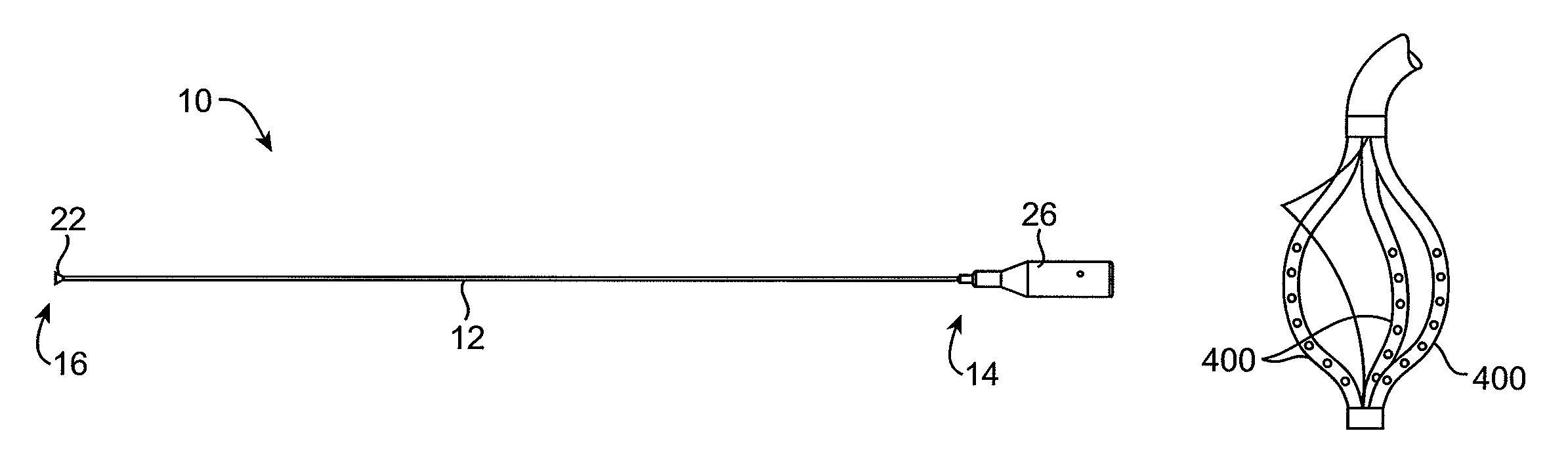
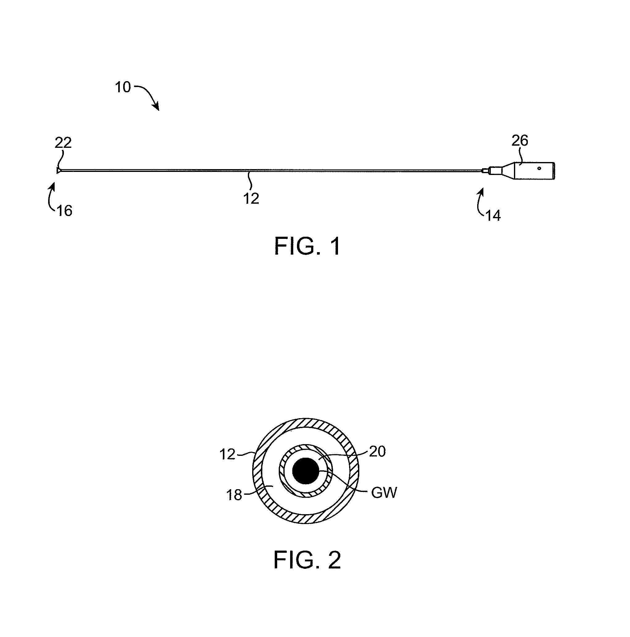
FIG. 1 illustrates a suction catheter constructed in accordance with the principles of the present invention.
FIG. 2 is a cross-sectional view of the catheter of FIG. 1.
FIGS. 3 and 4 are detailed views of the distal end of the catheter of FIG. 1, with FIG. 4 showing a suction housing in an expanded configuration.
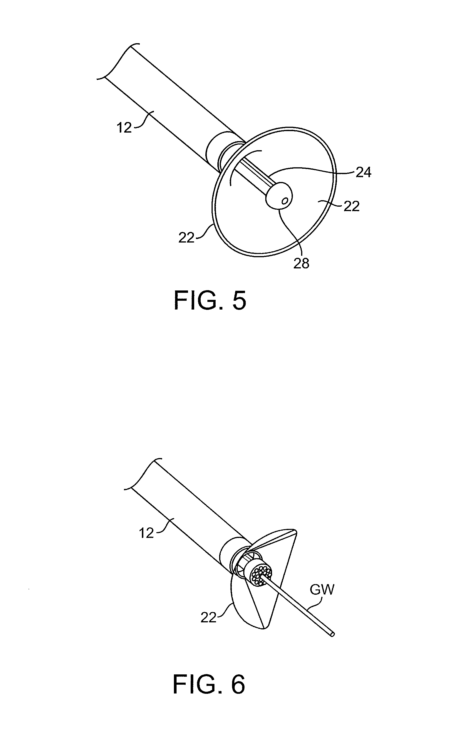
FIG. 5 is similar to FIG. 4, showing the catheter without a guidewire.
FIGS. 6-8 show modified suction housings.
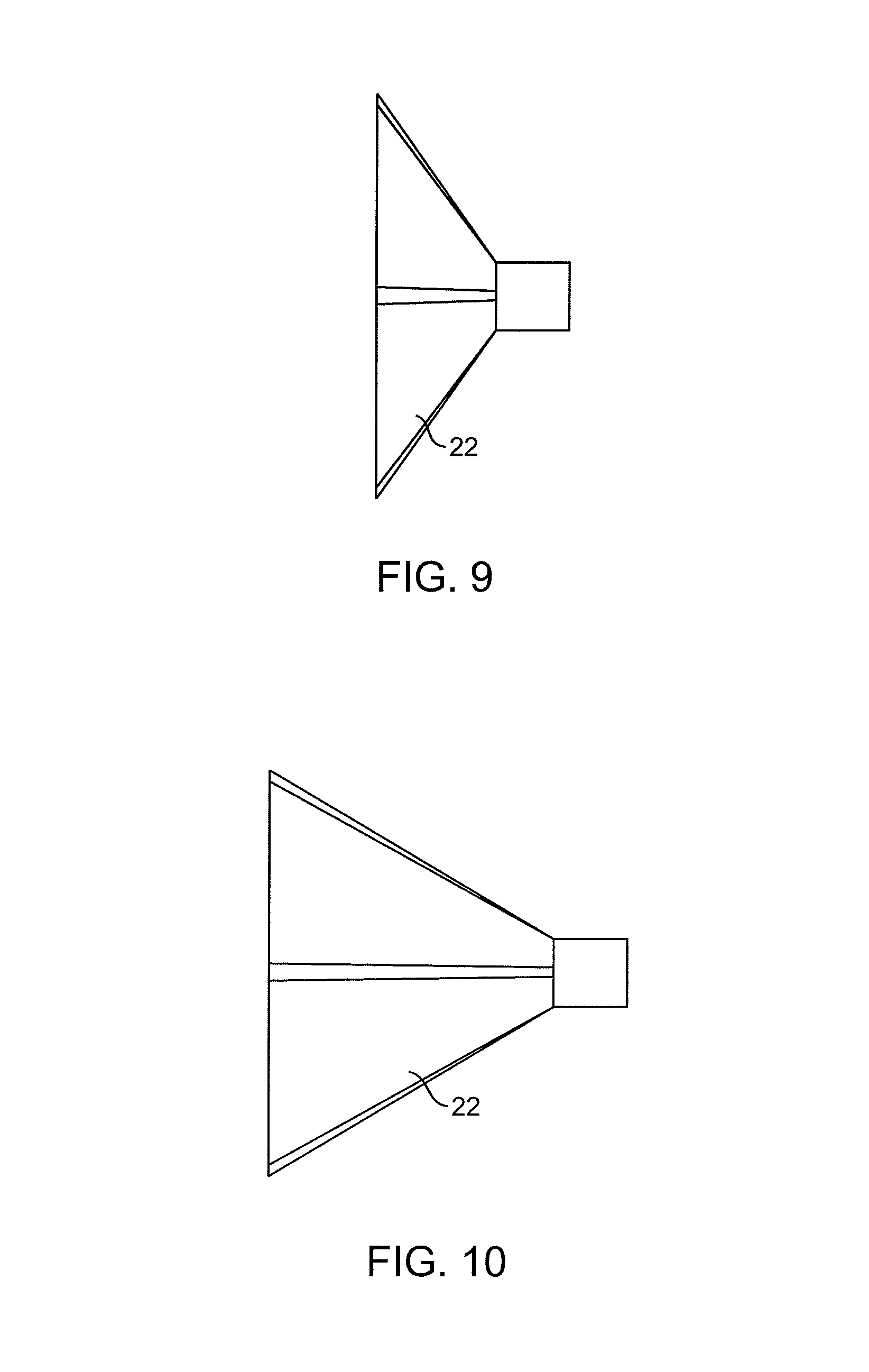
FIGS. 9 and 10 show suction housings having different depths.
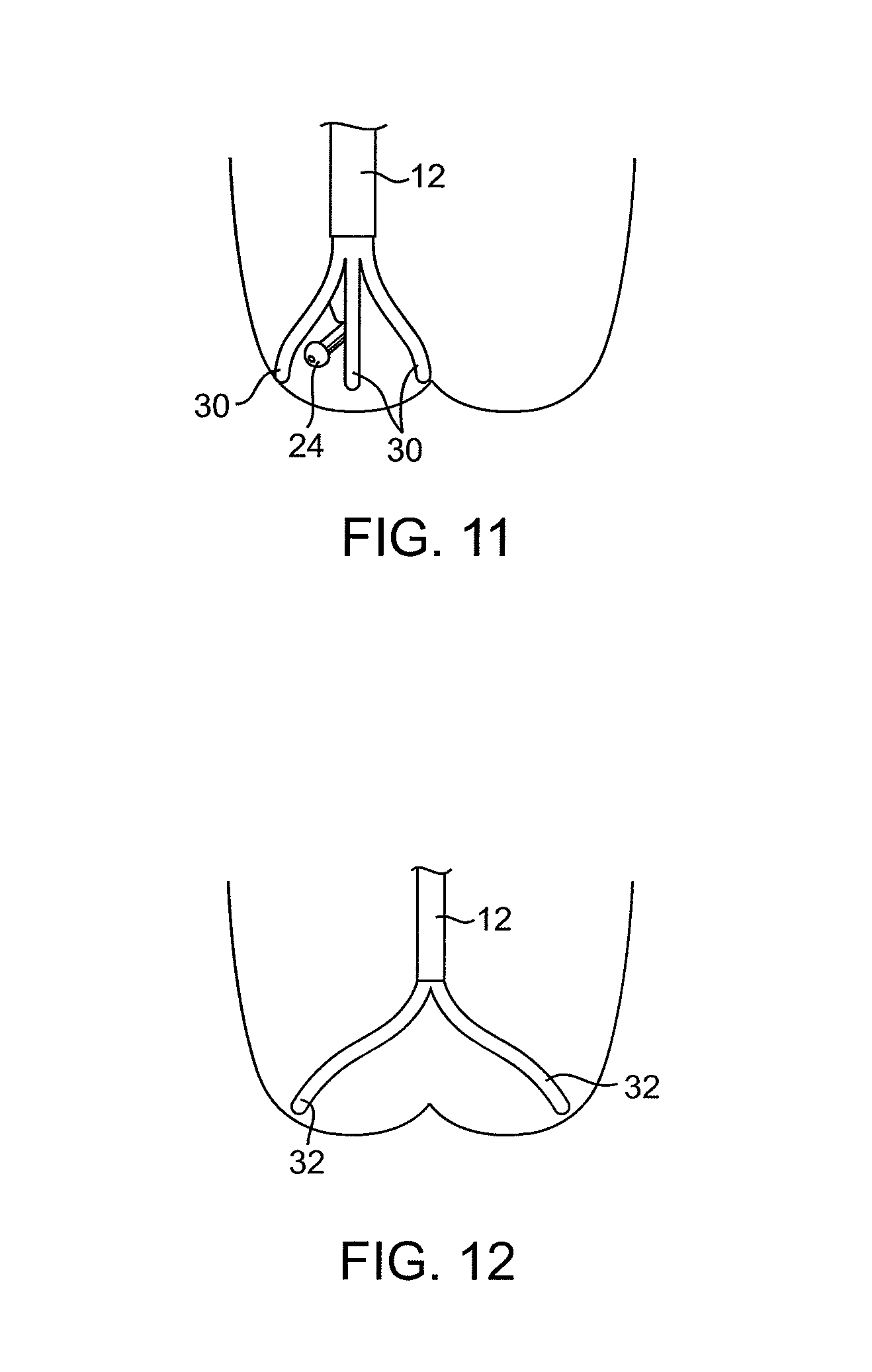
FIGS. 11-13 show suction housings having rigid or semi-rigid members around their circumferences.
FIG. 14 shows a suction catheter having a stabilizing structure near its distal end.
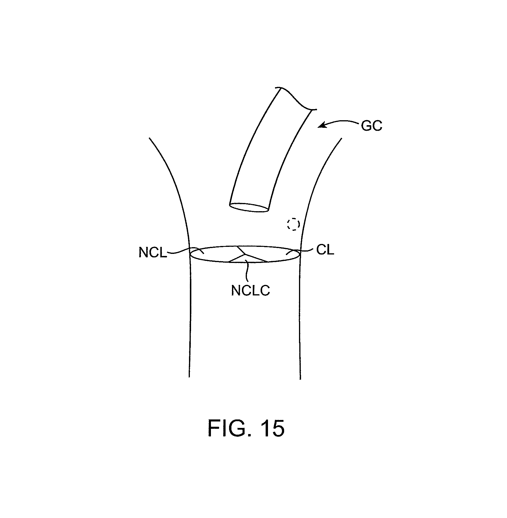
FIG. 15 illustrates how a guiding catheter would be used to place the catheters of the present invention above a treatment area.
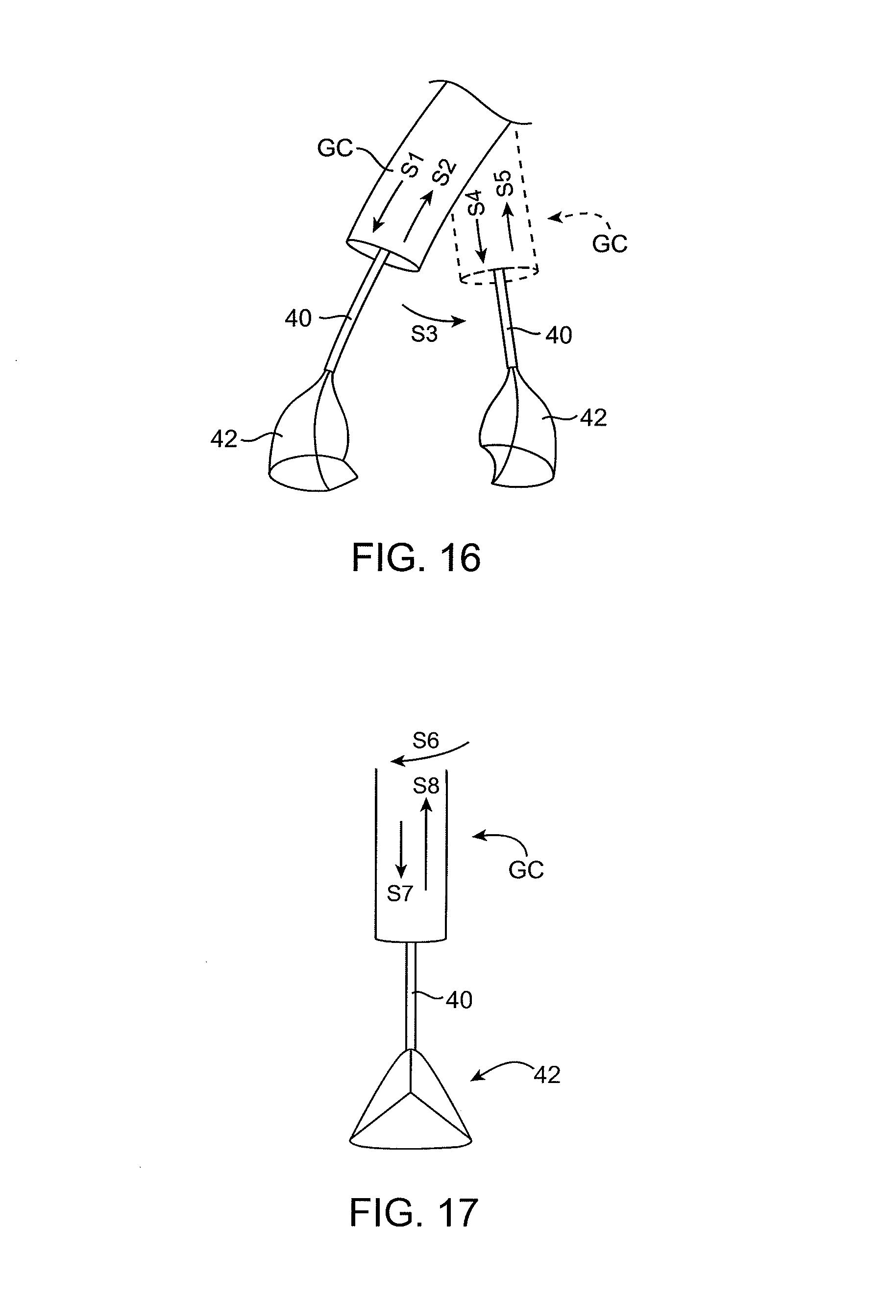
FIGS. 16 and 17 show how suction catheters would be placed through the guide catheters.
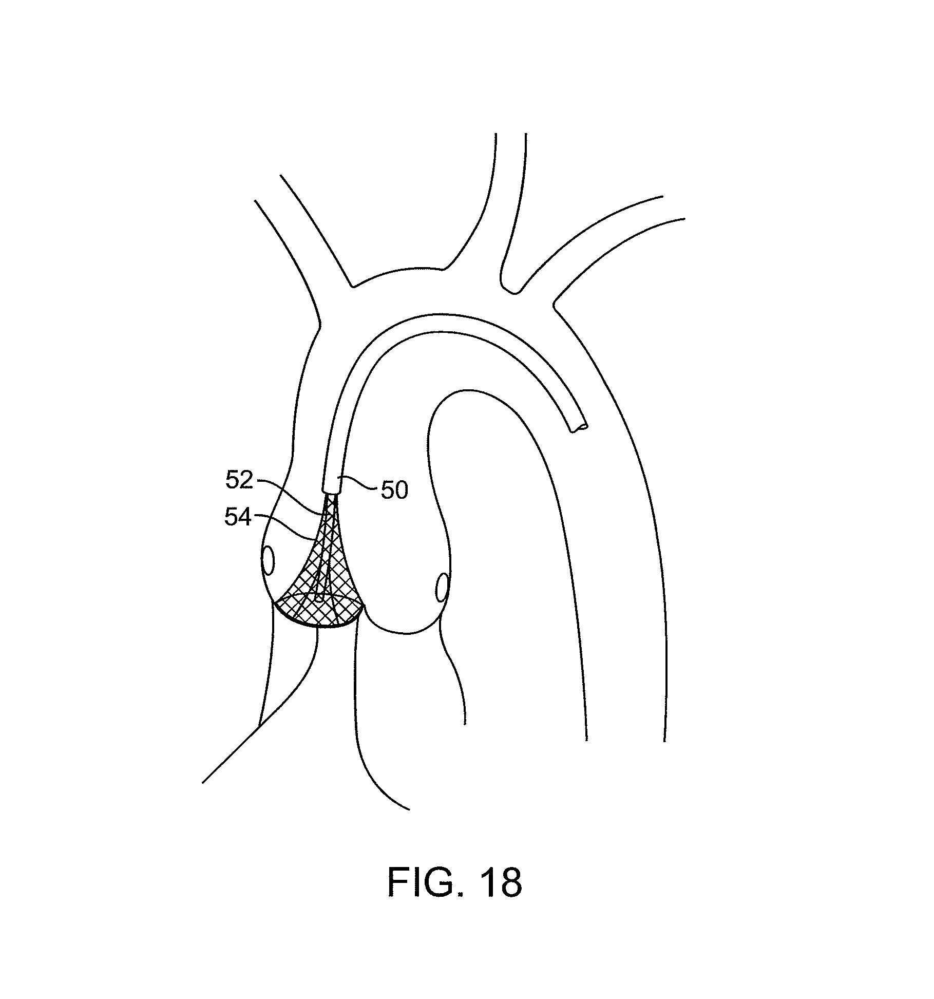
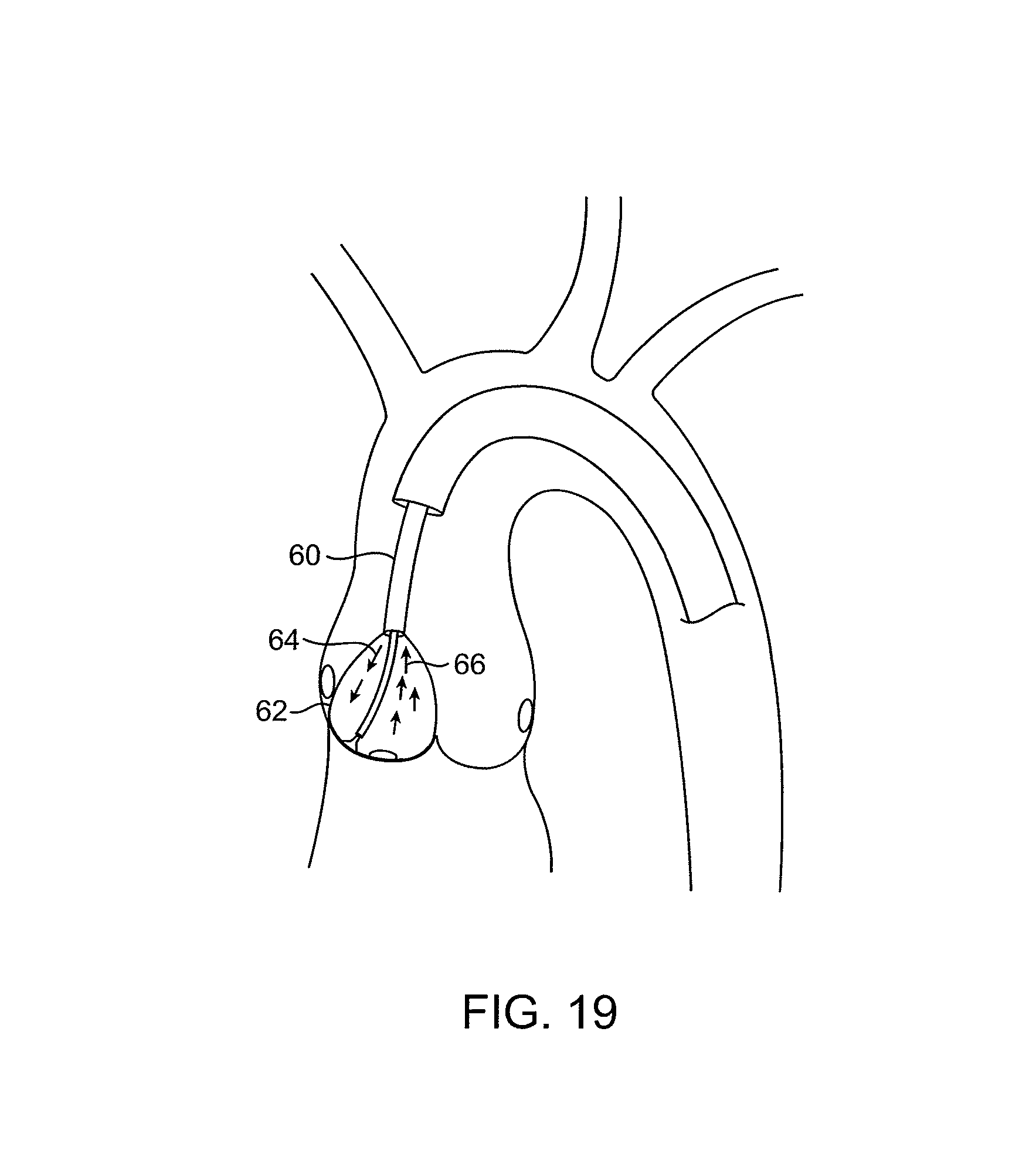
FIGS. 18-22 illustrate the use of treatment catheters having ultrasonic probes for decalcifying leaflets in accordance with the principles of the present invention.
FIG. 23 illustrates a catheter having a distal portion shaped to correspond to a shape of a targeted valve leaflet.
FIG. 24 illustrates a catheter having a distal end with an annular treatment surface adapted to apply energy to a valve annulus.
FIGS. 25A-25D illustrate catheters having different working ends in accordance with the principles of the present invention.
FIGS. 26-28 illustrate catheters having ultrasonic transmission members and enlarged working ends.
FIGS. 29-31 illustrate catheters having enlarged distal working ends with central lumens therethrough.
FIGS. 32 and 33 illustrate catheters having ultrasonic transmission elements adjacent a working end.
FIGS. 34-37 illustrate different patterns of motion which may be imparted by the electronic catheters of the present invention.
FIG. 38 illustrates a catheter having a force limiting feature.
FIGS. 39 and 40 illustrate a catheter having a deflectable distal end.
FIGS. 41 and 42 illustrate treatment catheters being advanced through a sheath.
FIG. 43 illustrates an ultrasonic catheter having a distal horn and a PZT stack.
FIG. 44 illustrates a suction housing placed over a PZT stack and ultrasonic horn in an embodiment of the present invention.
FIG. 45 illustrates a proximal housing for steering a distal end of the catheters of the present invention.
FIG. 46 illustrates use of a pair of suction catheters for treating a valve in accordance with the principles of the present invention.
FIG. 47 illustrates a catheter having an eccentrically loaded coil in the working end thereof.
FIGS. 48 and 49 show variations on the coil of FIG. 47.
FIGS. 50-52 illustrate catheters having mechanical elements in their distal ends.
FIGS. 53 and 54 show catheters having distal impellers and grinders.
FIGS. 55-57 illustrate catheters having disk-like grinders with abrasive surfaces.
FIGS. 58 and 59 illustrate rotating burrs which may be placed in the distal end of the catheters of the present invention.
FIG. 60 illustrates a catheter having a piezoelectric film element in its distal end.
FIGS. 61 and 62 show guiding catheters having filter elements at their distal ends which are used for introducing the catheters of the present invention.
FIG. 63 illustrates a filter device deployed to protect an entire region of treatment.
FIG. 64 illustrates a filter device covering a single leaflet.
FIG. 65 shows a filter shape optimized for a leaflet at the treatment site.
FIGS. 66-68 show catheter positions optimized for reducing calcium deposits.
FIG. 69 shows a device having an open lattice structure.
FIGS. 70-72 show implants formed from lattice wire structures.
FIGS. 73-76 illustrate implants having multiple loops.
FIGS. 77-80 show embodiments of the present invention for delivering drugs to the target treatment sites.
FIGS. 81 and 82 illustrate catheters having balloons with both drug release capability and blood perfusion capability.
FIGS. 83 and 84 show implantable devices having deployable struts.
FIGS. 85 and 86 show implantable devices having anchoring elements which lie against the wall of the aorta.
FIGS. 87-89 show embodiments where the device struts also provide for anchoring.
DETAILED DESCRIPTION OF THE INVENTION
Treatment Catheter Design--General
Treatment catheters 10 (FIG. 1) of the present invention typically comprise an elongate catheter body 12 that comprises a proximal end 14, a distal end 16, and one or more lumens 18, 20 (FIG. 2) within the catheter body. The distal end 16 may optionally comprise a suction housing 22 (FIGS. 4 and 5) that extends distally from the distal end of the catheter body 12 for isolating the leaflet during treatment as well as providing a debris evacuation path during treatment and protecting the vasculature from adverse embolic events. An energy transmission element 24 (e.g., a drive shaft, wire leads, or a waveguide-ultrasonic transmission element, or the like) may be positioned in one of the lumens in the elongate body 12 and will typically extend from the proximal end to the distal end of the catheter body. A handle 26 is coupled to the proximal end 14 of the elongate catheter body 12. A generator (e.g., RF generator, ultrasound generator, motor, optical energy source, etc.) may be coupled to the handle to deliver energy to a distal waking end 28, the energy transmission element 24 that is disposed within a lumen of the catheter body. As described herein, the distal working element 28 may be coupled to the distal end of the energy transmission element 24 to facilitate delivery of the energy to the calcification on the aortic valve.
Typically, the treatment catheters 10 of the present invention are configured to be introduced to the target area "over the wire." The treatment catheters may be positioned adjacent the aortic valve through a guide catheter or sheath. As such, the treatment catheters of the present invention may comprise a central guidewire lumen 20 for receiving a guidewire GW (FIG. 2). The guidewire lumen 20 of the treatment catheters of the present invention may also be used for irrigating or aspirating the target area. For example, while not shown, the handle may comprise one or more ports so as to allow for irrigation of the target leaflet and/or aspiration of the target area. An irrigation source and/or an aspiration source may be coupled to the port(s), and the target area may be aspirated through one of the lumen of the catheter and/or irrigated through one of the lumens of the catheter. In one embodiment, one of the irrigation source and aspiration source may be coupled to the central guidewire lumen (central lumen) and the other of the aspiration source and the irrigation source may be coupled to the lumen that is coaxial to the guidewire lumen. In some embodiments, however, there will be no inner guidewire lumen and the guidewire will simply extend through the ultrasound waveguide and the rotatable drive shaft, as shown in FIGS. 3, 4 and 6.
As noted above, the treatment catheters 10 of the present invention may comprise a suction housing positioned at the distal end of the catheter body having an expanded configuration and a retracted configuration and configured to conform to the valve leaflet to be treated. While the suction housing 22 may be fixedly attached at the distal end, in preferred embodiments, the suction housing is movable between a retracted configuration (FIG. 3) and an expanded configuration (FIGS. 4 and 5). A separate sheath may also be retracted to expose the suction housing and advanced to fold the housing. The suction housing may be made from silicone or urethane and may be reinforced with an internal frame or mesh reinforcement to provide structural support or to enhance placement of the housing on a specified area of the valve leaflet. The housing may further act as an embolic filter as detailed later in this specification.
In the embodiment of FIG. 4, the energy transmission element 24 is advanced beyond the distal end of the catheter body 12 and into the suction housing 22. The guidewire GW is positioned through an opening in the distal tip. As in FIG. 5, once the treatment catheter is positioned at the target area, the guidewire GW is withdrawn and the distal working element 28 is ready for use to treat the calcification.
In FIG. 6, the suction housing 22 is shaped to substantially conform to the shape of a bicuspid valve leaflet. By shaping the suction housing to conform to the shape of the leaflet, the suction housing may be better configured to isolate the target leaflet. In other embodiments, the suction housing may be shaped to substantially conform to a tricuspid valve (FIGS. 7 and 8), etc.
The depth of the suction housing may take many forms such that it is compatible with the valve to be treated. For example, the suction housing 22 may be shallow (FIG. 9) or deep (FIG. 10). The depth on the cup can reduce or eliminate obstructing the coronary ostia if one of the leaflets under treatment is a coronary leaflet.
The suction cups/housings may also have rigid or semi-rigid members around the circumference or part of the circumference of the housing to preferentially align the cup on certain valve features, such as the annulus. The suction cup housings have a depth range of 0.1'' to 0.5'' and a diameter of 15 mm to 30 mm. The cup or housing may have fingers 30 or longitudinal stabilizing elements 32 to assist in placing the housing against the valve as shown in FIGS. 11, 12, and 13.
Such stabilizing elements may also be in the form of pleats, rings or hemispherical elements, or other reinforcements to assist the device to seat within the annulus of the valve or against the leaflet. Such reinforcements or stabilizing elements may be formed of stainless steel, NiTi (superelastic or shape memory treated), Elgiloy.RTM., cobalt chromium, various polymers, or may be in the form of an inflatable ringed cup. The cup or housing of the present invention is intended to function to provide sufficient approximation with the treatment area so as to stabilize or localize the working element while also minimizing embolic events. It that sense, it is substantially sealing against the treatment region, but such seal is not necessarily an "airtight" seal, but an approximation that performs the desired functions listed above.
In addition, certain stabilizing devices 36, 38 may be located on the main catheter shaft 12 to provide stability within the aorta, and may, in some cases, extend through the valve leaflets L below the valve to further stabilize the treatment device, as shown in FIG. 14.
Given the variety of leaflet geometries (e.g. size, curvature) from leaflet to leaflet, and patient to patient, it may be desirable to provide a main treatment catheter through which a variety of sized and shaped cups or housings can be passed, depending on the particular geometry to be treated. For example, a system could include a main guide catheter GC placed over the treatment area as depicted in FIG. 15: The treatment area (leaflets) include the coronary leaflet (CL), the non-coronary leaflet (NCL) and the non-coronary leaflet (center) (NCLC). As shown below in FIG. 16, once the guide catheter GC is in place a first treatment catheter 40 having a distal housing 42 adapted to conform to the NCL is advanced as indicated by arrow S1. The leaflet is treated and the NCL housing catheter is withdrawn as indicated by S2. The guide catheter position is then adjusted as indicated by arrow S3 to better approximate the CL. CL housing catheter is the advanced through the guide as indicated by arrow S4. Once the CL position is treated, the CL housing catheter is removed as indicated by arrow S5. As further depicted in FIG. 17, the guide catheter GC is then repositioned to treat NCLC as indicated by arrow S6, and finally the NCLC housing catheter is advanced through the guide according to arrow S7. Once the treatment is complete, the NCLC is removed as indicated by arrow S8 and the guide is removed and procedure completed.
It is within the scope of the present invention to use any one of these steps, in any order to treat the targeted region, for example, one leaflet may be treated only, more than one leaflet, and in any order according to the type of calcification, health of the patient, geometry of the target region or preference of the operator.
Ultrasound Treatment Catheters
In accordance with one aspect of the present invention a treatment catheter 50 is provided having an ultrasonic probe for decalcifying the leaflet. An ultrasonic probe 52 may be surrounded by a frame or sheath 54. Both the frame and the sheath may be connected to a source of ultrasonic vibration (not shown). In certain embodiments, the probe 52 is surrounded by a sheath or housing that enables the system to be substantially sealed against the treatment surface via a source of suction attached at the proximal end of the catheter system and connected to the catheter housing via a suction lumen in the catheter body. Alternatively, the system may be placed or localized at the treatment site with a mechanical clip or interface that physically attaches the housing to the treatment area (annulus or leaflet). In operation, the ultrasonic probe 52 is activated to disintegrate the calcium on the leaflets, creating debris that may then be removed through a suction lumen in the catheter body 50. In some cases it may be desirable to also infuse saline or other fluids into the housing area simultaneously or prior to application of suction. It may be advantageous to provide a cooling fluid to the ultrasonic waveguide as well and to other embodiments such as one with a PZT stack at the distal end of the device. It may also be advantageous to infuse anti-calcification therapy to the site of the valve, including a ferric and/or stannic salt, or other solution as in known in the art to tan or otherwise make the leaflets resistant to calcium buildup, such as the type set forth in U.S. Pat. No. 5,782,931, the contents of which is expressly incorporated by reference herein. Another embodiment of an ultrasonic probe 60 having a silicone cup is shown in FIG. 19 where infusate is indicated by arrows 62 and aspirate is indicated by arrows 64.
In embodiments where a filter device 74 is disposed on the main catheter shaft (shown in FIG. 20), the ultrasonic probe 70 may be a separate element, allowing the ultrasonic treatment catheter 72 to move independently within the sealed region. The treatment probe 70 may be operated in a variety of directions and patterns that are further detailed in the specification, including sweeping in a circular pattern along the cusp of each leaflet and creating concentric circles during treatment to effectively treat the entire leaflet, if necessary. In the absence of a filter device, the ultrasonic element may be coaxial with the suction housing and adapted to move independently therewithin.
As shown in FIG. 21, in accordance with another aspect of the present invention, a treatment catheter 80 may be placed through a series of guide catheters 82, 84 to assist placement accuracy. The first guide member 84 may be placed and anchored in the aortic root using either the shape of the guide to anchor against the aortic wall, or a separate balloon or filter device to stabilize the guide or a stabilizing ring made from shape memory material or other suitable material that can provide stabilization to allow the catheter to be directed to the treatment site. A second steerable or articulable catheter 82 may then be placed through the initial guide to direct the treatment catheter to one area of the leaflet or other. The treatment catheter 80 may then be placed through the system once these guides are in place, and deployed directly to the targeted valve region. In the case of a method that treats one leaflet at a time, the steerable guide may then be actuated to target the next treatment location, thereby directing the treatment catheter (and related filtering devices) to the next site. It may only be necessary to place one guide catheter prior to the treatment catheter, or alternatively, the treatment catheter may be steerable, allowing it to be placed directly to the treatment site without the aid of other guide catheters. The guide catheter may also be steerable and an integral part of the treatment catheter. Steerable guides such as those depicted in US Patent Publications 2004/0092962 and 2004/0044350 are examples, the contents of which is expressly incorporated by reference in its entirety. Treatment device may then re-directed to a second treatment site, as shown in FIG. 22.
The distal portion 90 of the treatment catheters of the present invention may be shaped to substantially correspond to a shape of the targeted leaflet L (e.g., formed to fit within shape of the leaflet cusp, with the mouth of the housing being shaped to conform to the leaflet shape as shown in FIG. 23). This also enables the surface of the leaflet to be stabilized for treatment. The distal portion may have an internal frame that supports the distal section during deployment and treatment but is flexible such that it collapses into the treatment catheter or sheath to assist with withdrawal.
Alternatively, the treatment catheter 100 of the present invention may be formed having a circumferential, annular treatment 102 surface to apply energy/vibration to the annulus to be treated. In this embodiment the catheter may be placed antegrade or retrograde, or two circumferential treatment surfaces may be used in conjunction with each other, as shown in FIG. 24.
Various ultrasonic working ends may be used, depending on the type and location of the disease to be treated. For example, the distal tip of an ultrasonic catheter may be coupled to a ultrasound transmission member or waveguide. The distal tip may be chosen from the various examples below, including a blunt tip, a beveled tip, a rounded tip, a pointed tip and may further include nodules or ribs (FIG. 25C) that protrude from the surface of the tip to enhance breakup of calcium. Arrows show exemplary patterns of use.
The distal tip of the ultrasonic catheters of the present invention may also take the shape of the waveguide tips that are shown and described in U.S. Pat. No. 5,304,115, the contents of which is expressly incorporated by reference herein. U.S. Pat. No. 5,989,208 ("Nita"), the contents of which is expressly incorporated by reference herein, illustrate some additional tips in FIGS. 2-7A that may also be useful for decalcifying a valve leaflet.
The ultrasound transmission members of the present invention may comprise a solid tube that is coupled to an enlarged distal working end. A central lumen may extend throughout the ultrasonic transmission member and may be used for aspiration, suction, and/or to receive a guidewire. In the embodiment illustrated in FIGS. 26, 27 and 28, the enlarged working end 110 (which has a larger diameter than the elongate proximal portion), may comprise a cylindrical portion that comprises a plurality of elongated members 112. In the illustrated configuration, the elongated members are arranged in castellated pattern (e.g., a circular pattern in which each of the elongated members extend distally) and provide an opening along the longitudinal axis of the ultrasound transmission member. While the elongated members are cylindrically shaped, in other embodiments, the elongated members may be rounded, sharpened, or the like.
In a further embodiment of the distal working end, similar to the embodiment illustrated above, a central lumen may extend through the ultrasound transmission element and through the enlarged distal working end. In the configuration illustrated in FIGS. 29, 30 and 31, the distal working end 120 is enlarged and rounded.
In alternative embodiments, the portion of the ultrasound transmission element (or waveguide) that is adjacent the distal working end may be modified to amplify the delivery of the ultrasonic waves from the working end. The waveguide may comprises a plurality of axial slots in the tubing that act to create a plurality of "thin wires" from the tubing, which will cause the ultrasonic waves to move radially, rather than axially. The enlarged distal working end may then be attached to the plurality of thin wires. Two embodiments of such a configuration are illustrated in FIGS. 32 and 33. In an alternative embodiment, each castellation may be housed on its own shaft extending back to the proximal end of the device. Other potential tip geometries are depicted below.
The ultrasonic catheters of the present invention may be adapted to impart motion to the distal tip that is oscillatory, dottering, circular, lateral or any combination thereof. For any of such distal tips described herein, Applicants have found that the use of a small distal tip relative to the inner diameter of the catheter body provides a better amplitude of motion and may provide improved decalcification. In addition, an ultrasonic tip of the present invention can be operated in a variety of treatment patterns, depending on the region of the leaflet or annulus that is being treated, among other things. For example, the treatment pattern, either controlled by the user programmed into the treatment device, may be a circular motion to provide rings of decalcification on the surface being treated, a cross-hatching pattern to break up larger deposits of calcium (FIG. 24), or a hemispherical (FIG. 36) or wedge-shaped (FIG. 37) pattern when one leaflet or region is treated at a time. It is within the scope of the present invention to use combinations of any of the patterns listed, or to employ more random patterns, or simply a linear motion.
Certain safety mechanisms may be incorporated on the treatment catheter and related components to ensure that the treatment device does not perforate or otherwise degrade the leaflet. In one embodiment, a force limiting feature may be incorporated into the treatment catheter shaft as shown in FIG. 38, where a structure 140 can contract in response to force applied to catheter 142 in the direction of arrows 144.
In another embodiment, features of the catheter shaft may limit the force that is delivered to the tissues. A soft distal tip 150 (FIG. 39) on a relatively rigid catheter shaft 152, where the forces can deflect the tip, as shown in FIG. 40.
In addition, the treatment catheter 200 may be advanced through a sheath 202 that acts as a depth limiter to the treatment catheter as shown in FIGS. 41 and 42. These various safety features may be incorporated into any of the treatment devices of the present invention, regardless of the energy employed.
An assembly of an ultrasonic catheter of the present invention is shown in FIG. 43, including an ultrasonic transmission member 210, a transmission-head 212, a guide wire GW, a suction cup 214, a spring 216, and catheter body 218.
Another embodiment of an ultrasonic catheter 220 includes a PZT stack 222 and a distal horn 224 at the distal end of the device as shown in FIG. 44.
The advantage of the embodiment of FIG. 44 that it eliminates a long waveguide and the losses that occur when using a long waveguide. In this embodiment the suction housing would fit over the PZT stack and the ultrasonic horn. Certain useful ultrasound elements are depicted in U.S. Pat. No. 5,725,494 to Brisken, U.S. Pat. No. 5,069,664 to Zalesky, U.S. Pat. Nos. 5,269,291 and 5,318,014 to Carter, the contents of which are expressly incorporated by reference in their entirety.
The proximal end of the ultrasonic catheter of the present invention may be configured according to the schematic depicted in FIG. 45. Knobs 230 on a proximal housing 232 are coupled to control wires that are connected to the distal end of the device. These knobs operate to tension the control wires thereby manipulating the angle of the distal end. Controls 234 for the steerable guide, such as gearing, pins, and shafts, are housed in the control box 236 on which the knobs are located. The main body of the treatment device further comprises an outer shaft and an inner shaft connected to slide knob. In turn the inner shaft is operatively connected at the distal end of the device to the housing such that when the slide knob is retracted the housing is translated from a retracted position to an extended position, or vice versa. Further depicted in FIG. 45 is a drive shaft or drive coil 230 that is operatively connected to an energy source or prime mover, for imparting motion to the drive coil. Drive coil terminates in the distal end of the device at the working element that contacts the tissue to be treated. Alternatively, in designs utilizing ultrasound, the ultrasonic waveguide or transmission element may be positioned within the outer shaft and/or inner shaft.
Mechanical Treatment Catheter and Methods
In addition to ultrasound treatment catheters described above, the present invention further provides treatment catheters and methods that use mechanically activatable tips to mechanically disrupt or obliterate the calcium on the leaflets. In general, the catheters will comprise a catheter body that comprises one or more lumens. A drive shaft (or similar element) may extend from a proximal end of one of the lumens to the distal end of the lumen. A distal working element may be coupled to (or formed integrally from) the drive shaft and will be configured to extend at least partially beyond a distal end of the catheter body. The proximal end of the drive shaft may be coupled to a source of mechanical motion (rotation, oscillation, and/or axial movement) to drive the drive shaft and distal working element.
The catheters of the present invention may use a variety of configurations to decalcify the leaflet. Some examples of the working elements and distal ends of the catheter body that may be used are described below.
In one embodiment (FIG. 46), the distal end of the catheter 240 comprises a suction housing 242 that may be used to contact and/or isolate the leaflet that is being decalcified. While the suction housing is illustrated as a funnel shaped element, in alternative embodiments, the suction housing may be of a similar shape as the leaflets that are to be treated (as described above). The suction housing 242 may be fixedly coupled to the distal end of the catheter body 240 or it may be movably coupled to the distal end portion. In such movable embodiments, the suction housing may be moved from a retracted position (not shown), in which the suction housing is at least partially disposed within the lumen of the catheter body, to an expanded configuration (shown below). Alternatively, a mechanical clip, clamp or other fixation element may be used to localize the treatment device at the annulus or leaflet to be treated such as that depicted below, including an element placed from the retrograde direction and the antegrade direction to secure the leaflets.
In the configuration of FIG. 47, the distal working element may comprise a rotatable, eccentrically loaded coil 250. The distal portion of the coil may taper in the distal direction and may comprise a ball 252 (or other shaped element) at or near its distal end. Optionally, one or more weighted elements (not shown) may be coupled along various portions of the coil to change the dynamics of the vibration of the coil. As can be appreciated, if the weight is positioned off of a longitudinal axis of the coil, the rotation profile of the coil will change. Consequently, strategic placement of the one or more weights could change the vibration of the coil from a simple rotation, to a coil that also has an axial vibration component.
In another embodiment (FIG. 48), the working element may comprise an eccentrically loaded non-tapering coil 260. The coil may or may not comprise a ball or weight at its distal tip.
In yet another embodiment (FIG. 49), the distal coil may comprise an elongated distal wire tip 270 in which at least a portion extends radially beyond an outer diameter of the distal coil working element. As illustrated, the distal wire tip may comprise one (or more) balls or weights. The distal wire tip may be curved, straight or a combination thereof As an alternative to (or in addition to) the aforementioned distal coils, the distal working element may comprise a "drill bit" type impeller or a Dremel type oscillating or rotating member at the distal tip that is configured to contact the calcification and mechanically remove the calcification from the leaflet. As can be appreciated, such embodiments will be rotated and oscillated in a non-ultrasonic range of operation, and typically about 10 Hz to 20,000 Hz, preferably 100 Hz to 1000 Hz. In such configurations, rotation of the shaped impellers will typically cause the calcification debris to be moved proximally toward the lumen in the catheter body. In some configurations, the impeller may comprise rounded edges so as to provide some protection to the leaflets. In each of the above mentioned embodiments, a sheath may cover the rotating elements to provide protection or to provide more directed force by transmitting the rotational and axial movements through the sheath.
The working elements may also comprise mechanically rotating devices. In the embodiment of FIG. 50, an oval shaped burr 280 is shown that the orientation of which ranges from vertically aligned with the central axis of the device (rotating axis) to 90 degrees or more from the central axis of the device. This off axis orientation allows a range of debridement locations and may be more applicable for certain situations, such as stenoses that are located eccentrically within the valve annulus, or to treat leaflet surfaces that are angled with respect to the central axis of the device. Angulation of the treatment tip relative to the central axis of the treatment device facilitates fragmentation of the calcification by providing increased velocity at the tip region. A similar arrangement is shown in FIG. 51, but with a different shaped, more elongate burr 282. In addition, FIG. 52 shows a burr element 284 in the form of a disk having holes in the face of the disk to allow evacuation of debris through the burr element. It is within the scope of the present invention that any mechanical working elements may have a roughened surface, a carbide tip material, or diamond coating to enhance fragmentation of the targeted material. Representative burr elements are manufactured by several companies such as Ditec Manufacturing (Carpenteria, Calif.), Diamond Tool (Providence, R.I.), and Carbide Grinding Co. (Waukesha, Wis.).
In alternative methods, it may be possible to position an impeller element 290 (FIG. 53) proximal to the aortic valve and not actually contact the leaflets. The rotation of the impeller may cause a vortex to remove calcific material off of the leaflet and into the suction housing and catheter body. The impeller may take a variety of forms such as the one described in U.S. Pat. No. 4,747,821 to Kensey, the contents of which are expressly incorporated herein by reference.
In another configuration, a rotating grinder head 292 (FIG. 54) may be coupled to the distal coil 294. The rotating grinder distal tip can take a variety of shapes. In the configuration illustrated below, the grinder distal tip is convex shaped and comprises a plurality of holes that are in a radial circular pattern around a central opening that is in communication with an axial lumen of the drive shaft. In such a configuration, the grinder distal tip is symmetrically positioned about the longitudinal axis of the distal coil and the rest of the drive shaft. The radial openings allow for irrigation and aspiration of particles. In some configurations, the grinder distal tip may comprise abrasive material, such as diamond dust, to assist in removal of the calcific material from the aortic valve.
In another grinder distal tip configuration shown in FIGS. 55 and 56, the grinder distal tip may comprise a flat pate 300. The flat grinder distal tip may comprise an abrasive material, holes, and/or machined protrusions or nubs. Such elements may be used to enhance the calcification removal from the leaflet.
In an alternative configuration as shown in FIG. 57, a grinder distal tip 304 may be mounted eccentrically about the distal coil 306 so that upon rotation, the grinder tips may cover a greater surface area of the leaflet without having to enlarge the size of the grinder distal tip. The figure below illustrates the flat grinder distal tip, but it should be appreciated that any of the distal tips described herein may be mounted eccentrically with the distal coil.
In another embodiment, the distal working element may comprise a castellated mechanical tip, such as that shown above for the ultrasonic working element. Optionally, the castellated tip may have an impeller that is set back from the distal tip.
In yet another embodiment, the present invention may use the Rotablator device that is described in U.S. Pat. No. 5,314,407 or 6,818,001, the complete disclosure of which are expressly incorporated herein by reference, to decalcify a leaflet. The Rotablator (as shown below) may be used as originally described, or the distal tip may be modified by flattening the tip, applying diamond dust on the tip, making the distal tip more bulbous, or the like. See FIG. 58 which is taken from the '407 patent.
The air turbine used for the Rotablator may be used to power some or all of the aforementioned mechanically-based treatment catheters. The air turbine provides an appropriate amount of torque and speed for disruption of calcium on the leaflets. The torque and speed, combined with a low moment of inertia of the drive shaft and distal tips of the present invention, reduce the risk of catastrophic drive shaft failure. For example, when the distal tip becomes "loaded" due to contact with the calcific deposits, the speed of rotation will reduce to zero without snapping or wrapping up the drive shaft. As an alternative to the air turbine, it may also be possible to use a motor with an electronic feedback system that can sense torque and speeds such that the motor may be slowed down at appropriate times.
Some embodiments of the treatment catheter may comprise an optional sheath that surrounds the distal working element. As illustrated in FIG. 54, the sheath may comprise a spherical shaped distal tip 310 that surrounds the distal working element. An elongated proximal portion is attached to the spherical distal tip and is sized and shaped to cover some or all of the drive shaft that is within the lumen of the catheter body. The spherical shaped distal tip may comprise an opening 312 that will allow for the delivery of a media (e.g., contrast media, coolant, etc.) and/or for passageway of a guidewire. The mechanical element or ultrasonic transmission element may extend beyond the tip of the sheath. A similar depiction is shown in U.S. Pat. No. 6,843,797 to Nash, the contents of which are expressly incorporated herein by reference.
In some embodiments, the sheath may comprise bellows or a flexible portion that allows for the end of the sheath to bend, extend, and/or retract. The sheath will typically not rotate, and the sheath will typically be sized to allow the distal working element and the drive shaft to rotate within the sheath. Rotation of the distal working element within the sheath will articulate the sheath (which will depend on the shape and type of actuation of the drive shaft) and may create a "scrubbing effect" on the calcific deposits. Advantageously, the sheath will transmit the mechanical motion of the drive shaft, while providing a layer of protection to the leaflets by controlling the oscillation of the working element. The sheath may be made of a variety of materials as known in the art and reinforced in such a way as to withstand the friction from the rotation of the distal working element within the spherical distal tip Consequently, one useful material for the sheath is steel, or a braided or other catheter reinforcement technique.
In any of the mechanical embodiments, it may be desirable to circulate or inject a cooling fluid may be to decrease the heat energy seen by the tissue, and assist in the removal of debris during debridement. Such a fluid may also assist with tissue fragmentation by providing a cavitation effect in either the ultrasonic embodiments or the mechanical embodiments.
Virtual Decalcification Use of Microspheres and/or Microbubbles
As noted above, most embodiments of the ultrasound treatment catheters and the mechanical treatment catheters comprise a lumen that runs through the catheter body to the distal end. It may be useful to deliver a media, such as a cooling fluid, an ultrasound contrast fluid, or the like, through the lumen to the target leaflet to amplify the effect of the energy delivery to the embedded calcific nodules on the leaflet. In one preferred configuration, the media may comprise microspheres or microbubbles. One useful contrast media that may be used with the methods and treatment catheters of the present invention is the Optison.TM. contrast agent (GE Healthcare). Various depictions of techniques utilizing cavitation and/or microbubbles to enhance a therapeutic effect may be found in U.S. patent RE036939 to Tachibana, and U.S. Pat. No. 6,321,109 to Ben-Haim, the contents of which are expressly incorporated by reference herein in their entirety.
Delivery of the ultrasonic wave through the contrast media that contains the microbubbles can increase the amount of cavitation or fragmentation energy delivered to the leaflet. Applying suction during the procedure can also enhance the fragmentation energy as described by Cimino and Bond, "Physics of Ultrasonic Surgery using Tissue Fragmentation: Part I and Part II", Ultrasound in Medicine and Biology, Vol. 22, No. 1, pp. 89-100, and pp. 101-117, 1996. It has been described that the interaction of gas bodies (e.g., microbubbles) with ultrasound pulses enhances non-thermal perturbation (e.g., cavitation-related mechanical phenomena). Thus, using a controlled amount of contrast agent with microbubbles may enhance the removal of the calcification from the leaflets. A more complete description of the use of microbubbles with ultrasound energy is described in Guzman et al., "Bioeffects Caused by Changes in Acuostic Cavitation Bubble Density and Cell Concentration: A Unified Explanation Based on Cell-to-Bubble Ratio and Blast Radius," Ultrasound in Med. & Biol., Vol. 29, No. 8, pp. 1211-1222, 2003 and Miller et al., "Lysis and Sonoporation of Epidel moid and Phagocytic Monolayer Cells by Diagnostic Ultrasound Activation of Contrast Agent Gas Bodies," Ultrasound in Med. & Biol., Vol. 27, No. 8, pp 1107-1113, 2001, the complete disclosures of which are incorporated herein by reference.
It should be appreciated however, that the use of microbubbles are not limited to the ultrasound or mechanical treatment catheters. For example, as shown below, the contrast media may be used with an RF catheter or a piezoelectric-based catheter. In the RF catheter embodiment, the catheter body may comprise two RF electrodes positioned at or near the distal end of the catheter. The media with the microbubbles may be delivered to the target leaflet through the lumen of the catheter, and an RF energy may be delivered between two leads to deliver energy to the microbubbles. In some embodiments, it may be desirable to deliver RF energy to the calcification on the leaflets without the use of the microbubbles. In other embodiments, it may be desirable to use other types of energy sources to deliver energy to the leaflets.
As an alternative to RF electrodes, it may be possible to position a piezo film 330 at the distal tip of the catheter (FIG. 60). Wire leads will extend through, within (or outside) the lumen of the catheter body and will be coupled to a generator. If the wire leads are disposed within the lumen of the catheter body, the catheter may comprise an inner tube to insulate the wires. The media may be delivered through the inner lumen of the catheter body and exposed to the piezo film at the distal end of the catheter body, and the energy may be delivered from the piezo film and into the media with the microbubbles.
Protection
In a further aspect of the present invention, protection devices and methods may be used to trap and evacuate debris from the treatment site. In one embodiment shown in FIGS. 61 and 62, a filter device 336 is located on the shaft of a guide catheter 338. This structure may also provide anchoring of the guide catheter in the aortic root to provide a stable access system to the valve or placing additional treatment catheters.
In another embodiment (FIG. 63), a filter device is deployed to protect the entire region of treatment and may include a systemic filtering device 340 such as those where blood and aspirate are removed from the arterial side of the vasculature, filtered and then infused back into the venous circulation, further details in U.S. Pat. No. 6,423,032 to Parodi, the disclosure of which is expressly incorporated herein by reference. A suction port 342 surrounds the ultrasound probe 344 at the distal end of catheter 346.
It may be advantageous to have filtering applied more locally closer to the treatment site (e.g. one leaflet at a time), to protect local structures such as the ostium of the coronaries located just above the aortic valve. Such a filtering device may be used in conjunction with treatment devices, such as the ultrasonic suction catheter shown in FIG. 64, where filter device 350 covers a single leaflet which is also engaged by ultrasonic probe 352 at suction port 354. Further, the filter shape may be optimized to access the most relevant leaflet or treatment site, as shown in FIG. 6. Any of the above filtering or protection systems may be used with any of the treatment catheters disclosed herein.
Numerous features of the present invention aid in directing, positioning and stabilizing the treatment catheter optimally at the site of the disease to be treated. In addition to catheter and guide features, baskets, anchor or filter configurations that seat within the valve, certain methods may be used to position the catheter. For example, the heart may be connected to a pacing lead and the heart then paced at an increased rate, for example 200 beats per minute, which then holds the aortic leaflets in a relatively fixed location arresting blood flow and allowing the treatment catheter of the present invention to be applied to at least one leaflet. Following placement of the catheter, such as a suction housing, pacing is stopped, and the remaining leaflets not engaged by the catheter, function normally. In the event that all leaflets are engaged at once, it may be necessary to provide flow through the treatment catheter, such as in a perfusion balloon or device known in the art, some features of which are shown in U.S. Pat. No. 4,909,252 to Goldberg the disclosure of which is expressly incorporate by reference herein.
Imaging
Features of the present invention include various devices and methods for monitoring and imaging prior to, during and post procedure. Various imaging modalities may be employed for this purpose, including intracardiac echocardiography (ICE), transesophageal echocardiography (TEE), fluoroscopy, intravascular ultrasound (IVUS), angioscopy, infrared, capacitive ultrasonic transducers (cMUTs) available from Sensant, Inc./Seimens (San Leandro, Calif.) or other means known in the art. For example the treatment catheter may have an imaging device integrated into the housing or treatment element catheter shaft, such as a phased array intravascular ultrasound element. In some embodiments it may be advantageous to construct the device of the present invention so that they working element is a separate, removable element that is coaxial with the sheath to enable the operator to remove the working element and place an imaging element in its place.
Imaging may become critical at various stages of the procedure, including diagnosing the type and location of the disease, placing the treatment catheter, assessing the treatment process, and verifying the function of the valve once it is treated. Imaging devices may be placed locally at the treatment site, such as on the catheter tip, or catheter body, alongside the treatment catheter, or in more remote locations such as known in the art (e.g. superior vena cava, esophagus, or right atrium). If the imaging element is placed on the treatment catheter, it may be adapted to be "forward looking" e.g. image in a plane or multiple planes in front of the treatment device.
It is also within the scope of the present invention to employ interrogation techniques or other imaging modalities, such as infrared imaging to see through blood for direct visualization of the treatment site, or elastography, the ultrasonic measurement of tissue motion, to sense what type of tissue is targeted, e.g. leaflet tissue or calcium, or to sense the region of the valve that is most calcified. Elastography in this context may be performed using an intravascular ultrasound (IVUS) catheter, either a mechanical transducer or phased array system, such as those described in "Characterization of plaque components and vulnerability with intravascular ultrasound elastography" Phys. Med. Biol. 45 (2000) 1465-1475, the contents of which is expressly incorporated by reference herein. In practice, the transducer may be advanced to a treatment site on the valve, and using either externally applied force, or "periodic excitation" of the tissue region either by externally applied force or the naturally occurring movement in the tissue itself (such as the opening and closing of the valve leaflets), an initial baseline reading can be taken. This baseline could be set by engaging the region or leaflet to be treated with a suction catheter of the present invention (including circulating fluid within the treatment site), inserting an ultrasound transducer through the treatment catheter up to the treatment site, and interrogating the targeted region with the ultrasound transducer to establish the elasticity of the region (stress/strain profile). For a particular region of the leaflet, infusion can then be stopped, putting the leaflet under additional stress (by suction alone) and the displacement in the stress/strain profile can be noted and evaluated to direct the treatment device to those locations showing less elasticity ("stiffer" regions indicating the presence of calcific deposits. See also those techniques set forth in "Elastography--the movement begins" Phys. Med. Biol. 45 (2000) 1409-1421 and "Selected Methods for Imaging Elastic Properties of Biological Tissues" Annu Rev. Biomed. Eng. (2003) 5:57-78, the contents of which are expressly incorporated by reference herein.
In some instances, for example with ultrasound or laser, the same transducer or fiber optic that is used to interrogate or image the region may also be used to break up or treat the underlying calcific deposits. Certain parameters may be adjusted to transition the therapy device from diagnostic to therapeutic, including frequency, power, total energy delivered, etc.
In addition, other characterization techniques may be employed to both target the calcific region to be treated or assess the result of a treatment, including MRI, Doppler, and techniques that utilize resistivity data, impedance/inductance feedback and the like. Using imaging and other monitoring techniques such as those described, can result in a more targeted procedure that focuses on removing calcific deposits and limits potential tissue damage to the leaflet and annulus that can lead to an unwanted proliferative response.
Energy Sources/Methods of Treatment
A variety of energy modalities may be used in the treatment catheters envisioned by the present invention. Those modalities more specifically useful for breaking down or obliterating calcific deposits may be ultrasonic energy, laser energy and the like. Specifically, some Er:YAG lasers may specifically target calcium when operated in appropriate ranges. Some detail of targeted bone ablation supports this as found in "Scanning electron microscopy and Fourier transformed infrared spectroscopy analysis of bone removal using Er:YAG and CO2 lasers" J Periodontol. 2002 June; 73(6):643-52, the contents of which are expressly incorporated by reference herein. Alternatively, energy may be delivered to selectively remove tissue from around or over a calcium deposit by employing a resurfacing laser that selectively targets water-containing tissue resulting in controlled tissue vaporization, such as a high-energy pulsed or scanned carbon dioxide laser, a short-pulsed Er:YAG, and modulated (short-and-long-pulsed) Er:YAG system. This application of energy may be useful for accessing plaque or calcium that is distributed between the leaflets (spongiosa). In practice, it would be desirable to remove the layer of tissue covering the deposit so that the majority of the leaflet remained intact and shielded from unnecessary thermal damage. Further, such specific tissue destruction may also be applied to the removal of scar tissue or regions of hypertrophy within the valve annulus as part of the treatment of the present invention.
The ultrasonic treatment catheters of the present invention may be operated in ranges between 5 and 100 kHz, for example 10-50 kHz, with an oscillation rate in the range of 10-200 microns, for example 75-150 microns (maximum travel between 20-400 microns). In addition, to minimize potential for thermal damage or other tissue damage, it may be advantageous to operate the treatment devices in a pulsed manner, such as a 5-50% duty cycle, for example a 5-20% duty cycle, and to minimize the tissue that is exposed to the energy application by carefully targeting the delivery of energy to the most diseased regions.
In addition, it may be advantageous to focus the treatment on certain locations of the diseased valve where removing or reducing calcium deposits result in the greatest amount of restored leaflet mobility and resulting valve function. For example, deposits within the annulus of the valve, at the nadir of the leaflet, in the mid-section of the leaflet, or at the commissures may be initially targeted. A schematic depiction of these various positions with the valve are depicted in FIGS. 66, 67, and 68, where FIGS. 67 and 68 are cross-sections along lines A-A and B-B of FIG. 66, respectively.
Depending on the type and frequency of energy used, the treatment catheters of the present invention may also be utilized to not only remove calcium, but also to remove or obliterate the leaflet itself, such as in preparation for implantation of a minimally invasive prosthetic valve, such as those disclosed in U.S. Pat. Nos. 5,840,081 and 6,582,462 to Anderson, US Patent Application 2004/0092858 to Wilson, PCT Publication WO 2004/093728 to Khairkhahan, WO 2005/009285 to Hermann and the like, the disclosures of which are expressly incorporated herein by reference. Pre-treatment with devices of the present invention may facilitate placement of such prosthetic valves since removing calcium from the site of implantation may reduce perivalvular leak, dislodgement, and may result in a larger prosthesis being implanted due to an increased effective valve orifice.
Implantable Devices
A. As an alternative or adjunct to the devices described above which are removed once the repair is achieved, devices may be provided which are temporarily or permanently implanted across or within the aortic valve. The devices which appear below are all intended to remain for at least a period of time within the body after the repair of the stenosis has been completed in order to prevent or delay the valves from degenerating, by either recalcifying, fusion of leaflets, and restenosing. An implant of the present invention is depicted in FIG. 67 in either a sub annular 360 or supra annular position 362.
In some embodiments, it may be desirable to place an implant such as the coil depicted below, to extend both sub annular and supra annular to provide additional support to the valve and provide a greater treatment area across the valve. The coil design of this embodiment has a single strut that joins the two ring portions but is low profile enough that is does not occlude the coronaries just above the valve annulus. See, FIG. 68. Because of its open structure, the supra annular portion of the implant can extend above the coronaries into the aortic root for additional anchoring. See, FIG. 69.
In a further embodiment, the implant may be formed of a wire, series of wire, or cellular structure similar to that used in peripheral or coronary stents. To better seat in the valve annulus, or below the valve, it may be advantageous to form the implant ring to follow the cusps of the valve, in a sinusoidal form. In addition, the implant ring may have struts that extend to seat against the annulus of the valve to provide structure or further disseminate a pharmacologic coating at specific valve sites. See, FIGS. 70, 71, and 72.
In yet another embodiment, the implant may be formed of multiple loops, such as three loops 120 degrees from each other. See, FIGS. 73-76.
In this embodiment, and others depicting wire forms, the wire may have a diameter between 0.020'' and 0.250'' depending on the force desired. In addition, the wire may be flat and the structure may include a mesh between the loops to provide a larger surface area for supporting the valve or delivery the pharmacologic agent. The loops of this device may be moved distally and proximally in a cyclic way to further open the valve leaflets and disrupt plaque as a stand alone therapy. The device may then be permanently implanted as detailed above. It may be desirable to recapture the device, either once the valve has been treated, or during positioning of the permanent implant to ensure proper placement. A recapture device may be the delivery catheter from which the implant is deployed, or may include an expandable funnel on the distal end of a retrieval catheter or may include any number of mechanical devices including a grasper or a hook that mates with a hook on the implant, or grasps the implant at some point such that it may be drawn into the delivery sheath and removed from the body.
The structure of any of the implants described herein may have surface enhancements or coatings to make them radiopaque or echogenic for purposes of procedure assessment as is known in the art. As is further known in the art in the field of coronary artery stenting, the devices described may be permanent, removable, or bio-erodable. They can incorporate anti-restenosis agents or materials such as those set forth above, in the form of coatings, holes, depots, pores or surface irregularities designed into or applied onto the devices. In addition, the implants can be formed of certain calcification resistant materials such as those set forth in U.S. Pat. No. 6,254,635, the contents of which are expressly incorporated by reference herein. Further, implants of the present invention may be configured to emit a slight electrical charge. Since calcium is positively charged, it may be advantageous to repel calcium by positively charging the surface of the aortic implant. In addition, electrical energy may be supplied by the implant to minimize calcification by an implantable pacemaker type device as described in U.S. Pat. No. 6,505,080, which is expressly incorporated by reference herein.
Further, it is within the scope of the present invention to combine certain mechanical procedures and implants with various appropriate pharmacologic agents such as those listed previously. Anti-restenosis agents which may be useful in this application may be chosen from any of the families of agents or energy modalities known in the art. For example, pharmaceutical agents or their analogues such as rapamycin, paclitaxel, sirolimus or nitric-oxide enhancing agents may be coated onto these devices using drug eluting coatings, incorporated into intentionally created surface irregularities or specific surface features such as holes or divots. The devices may be designed for drug infusion through the incorporation of coatings or other surfaces to adhere the agents to the implants utilized to perform the procedures of the present invention, or may be prescribed for oral administration following procedures of the present invention. For example, following a treatment of the present invention, a patient may be prescribed a dose of statins, ACE inhibitors or other drugs to prolong the valve function provided by the intervention.
FIGS. 77-89 represent various embodiments of systems intended for acute or sub-chronic procedures. These devices may be placed across the aortic valve and expanded to reopen the aortic valve, and then left in place for a period of time in order to expose the treated valve to anti-restenosis agents or energy modalities designed to facilitate the repair and/or to prevent restenosis. The device shown in FIGS. 77 and 78 features mechanical vanes 400 which extend outward to engage and separate the fused leaflets at the commissures. The vanes may be made of any suitable metal, plastic or combination. They may be self expanding (made from nitinol or elgiloy, for instance) or they might be mechanically actuated using a pneumatic, hydraulic, threaded or other mechanical actuation system. The vanes might be deformable members as shown above, or each vane might be made up of several more rigid parts connected at hinged portions to allow expansion and contraction of the unit. The vanes may be designed with a cross section which is rectangular in shape, with the narrower edge designed to facilitate separation of fused leaflets and to fit within the commissures without impacting the ability if he valves to close. The wider face of these rectangular vanes would contact the newly separated edges of the leaflets. As an alternative to the rectangular cross section, the vanes might be designed to have more of a wing-shaped or other cross sectional shape to minimize turbulence within the bloodstream and to minimize trauma to the valve leaflets.
The device of FIGS. 79 and 80 shows a balloon system to be used in accordance with the inventive methods. The balloon 410 may feature a plurality of holes 412 to be used for the infusion of anti-restenosis agents as described in more detail below. These holes maybe small enough to allow only a slight weeping of the agents to be infused, or they might be of a size which would allow more rapid infusion or a greater volume of infusate to be delivered. The holes might be placed in even distribution around the circumference of the balloon, or they might be placed to align more directly with the location of the commissures.
The device of FIGS. 81 and 82 comprise a balloon system which combines features of FIGS. 77 and 78 with those of 79 and 80. Several balloons are placed such that each balloon aligns with a commissure 424. Inflation of this device may allow continued perfusion of blood out of the heart and into the body which the device is in place. This in turn might low for more prolonged delivery of anti-restenosis agents. Holes might be placed on the balloons of FIG. 3 similar to the description for the holes on the device in FIGS. 79 and 80.
Anti-restenosis agents which may be useful in this application may be chosen from any of the families of agents or energy modalities known in the art. For example, pharmaceutical agents or their analogues such as rapamycin, paclitaxel, sirolimus or nitric-oxide enhancing agents may be coated onto any of the inventive devices using drug eluting coatings, incorporated into intentionally created surface irregularities or specific surface features such as holes or divots. As described, the devices may be designed for drug infusion through the incorporation of infusion channels and infusion holes in the work-performing elements of the devices such as the balloons or commissurotomy vanes shown in the drawings.
Energy delivery may be achieved by several different modalities and for different purposes. Radiofrequency energy can be applied by energizing the commissurotomy vanes or by using the pores on the balloons to achieve a wet electrode. Microwave, ultrasound, high frequency ultrasound energy or pulsed electric fields (for the purpose of inducing cellular electroporation) might be used by incorporating antennae or electrodes into the vanes, balloons or catheter shafts that support these work performing elements. Cryotherapy can be achieved by circulating cooling fluids such as phase-change gases or liquid nitrogen through the work performing elements. Multiple modalities might be incorporated into a single device for achieving the goal of durable aortic valve repair.
This energy may be used to facilitate the valve repair, for instance by making easier the parting of fused leaflets. Alternatively, the energy may be used to delay or prevent restenosis of the treated valve. One example of the use of energy delivery for the prevention of restenosis is the use of pulsed electric fields to induce cellular apoptosis. It is known in the art that the application of pulses of electricity on the order of nanosecond duration can alter the intracellular apparatus of a cell and induce apoptosis, or programmed cell death, which is known to be a key aspect of the mechanism of action of the clinically proven anti-restenosis drugs such as paclitaxel or sirolimus.
These agents or energy applications might be administered while the patient is in the catheterization lab, over the course of minutes to hours. Alternatively, the devices may be designed to allow the patient to return to the hospital floor with the device in place, so that the infusion of agents or the application of energy could proceed over the course of hours or days.
B. As an alternative or adjunct to the devices described above which are removed once the repair is achieved and administration of the anti-restenosis agents is completed, devices may be provided which are temporarily or permanently implanted across or within the aortic valve. The devices which appear below are all intended to remain for at least a period of time within the body after the repair of the stenosis has been completed in order to prevent or delay the valves from readhering to one another and restenosing.
The devices described may be permanent, removable, or bio-erodable. They can incorporate anti-restenosis agents or materials into coatings, holes, depots, pores or surface irregularities designed into or applied onto the devices
The struts 430 may be made of any suitable metal, plastic or combination as shown in FIGS. 83 and 84. They may be self expanding (made from nitinol or elgiloy, for instance) or they might be mechanically actuated during implantation using a pneumatic, hydraulic, threaded or other mechanical actuation system and then locked into their final position prior to deployment of the device from the delivery system. The struts might be deformable members as shown above, or each strut might be made up of several more rigid parts connected at hinged portions to allow expansion and contraction of the unit. The struts may be designed with a cross section which is rectangular in shape, with the narrower edge designed to facilitate separation of fused leaflets and to fit within the commissures without impacting the ability if he valves to close. The wider face of these rectangular struts would contact the newly separated edges of the leaflets. As an alternative to the rectangular cross section, the struts might be designed to have more of a wing-shaped or other cross sectional shape to minimize turbulence within the bloodstream and to minimize trauma to the valve leaflets.
FIGS. 85-89 show alternate designs for the implantable device. It should be noted that any design for the implant which achieves the goals of providing long-term anti-restenosis agents or energy modalities to the treated regions of the repaired leaflets should be considered as subjects of this invention. Anchoring elements which lie against the wall of the aorta and are generally contiguous with the struts (as shown in FIGS. 83 and 84), which join in the center of the aorta before reforming with the struts (as in FIGS. 85 and 86), or designs in which the struts themselves are the anchoring elements (as in FIGS. 87-89) are all embodiments of the subject invention.
The implantable and bio-erodable devices might all feature pharmaceutical agents or their analogues such as rapamycin, paclitaxel, sirolimus or nitric-oxide enhancing agents, which may be coated onto any of the inventive devices using drug eluting coatings, or incorporated into intentionally created surface irregularities or specific surface features such as holes or divots.
Additional anti-restenosis agents or energy modalities might be delivered separate from and/or in addition to those agents that are incorporated onto the implant, for instance as a feature of the delivery system.
While the invention is susceptible to various modifications, and alternative forms, specific examples thereof have been shown in the drawings and are herein described in detail. It should be understood, however, that the invention is not to be limited to the particular forms or methods disclosed, but to the contrary, the invention is to cover all modifications, equivalents and alternatives falling within the spirit and scope of the disclosure and appended claims.
* * * * *
References
D00000
D00001
D00002
D00003
D00004
D00005
D00006
D00007
D00008
D00009
D00010
D00011
D00012
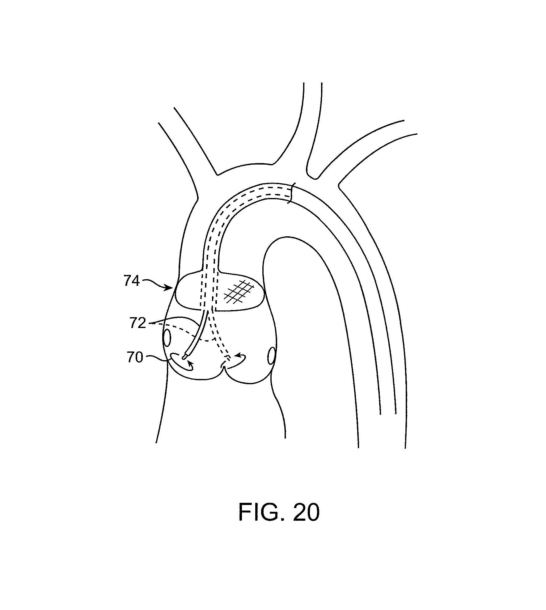
D00013
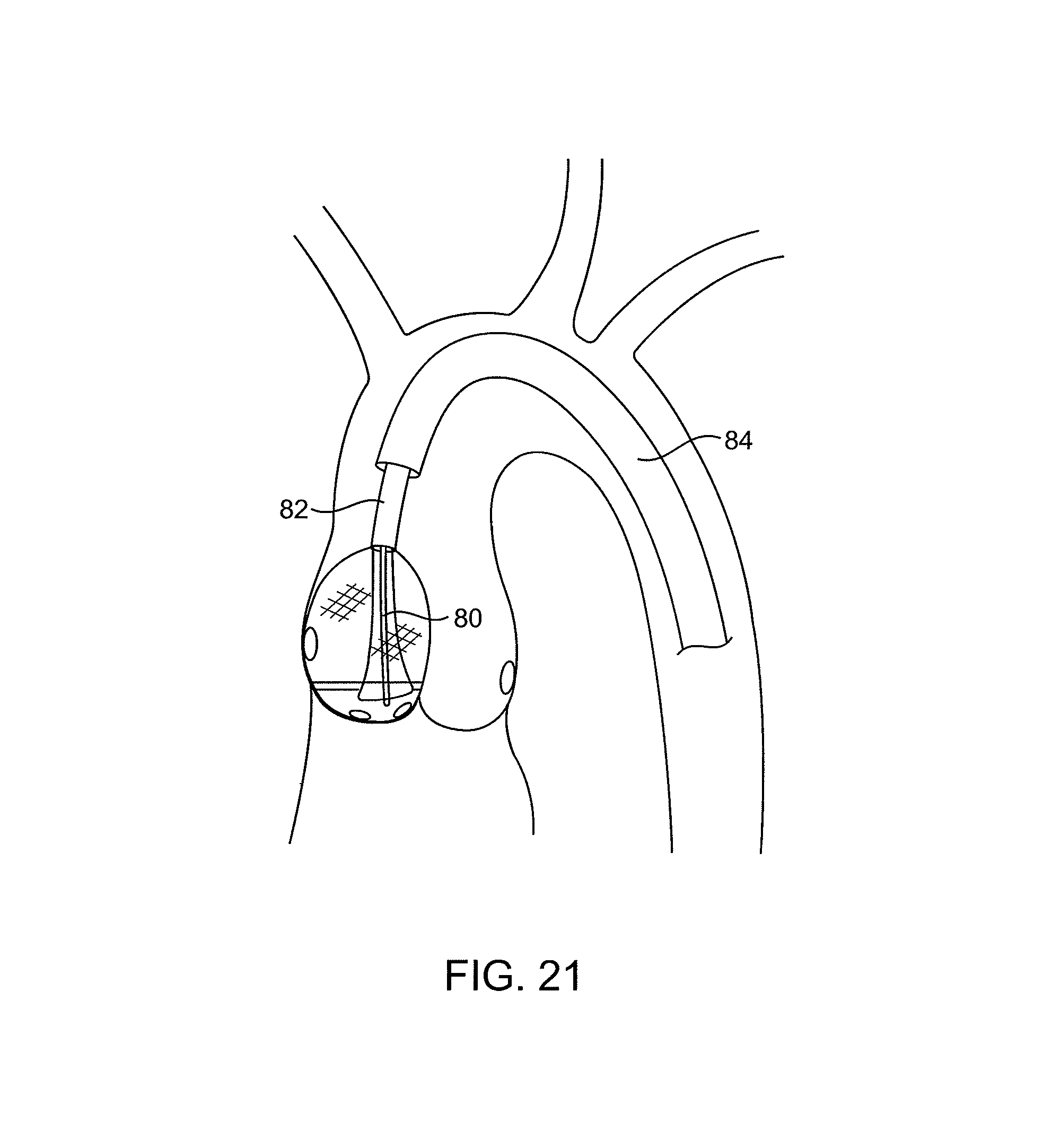
D00014
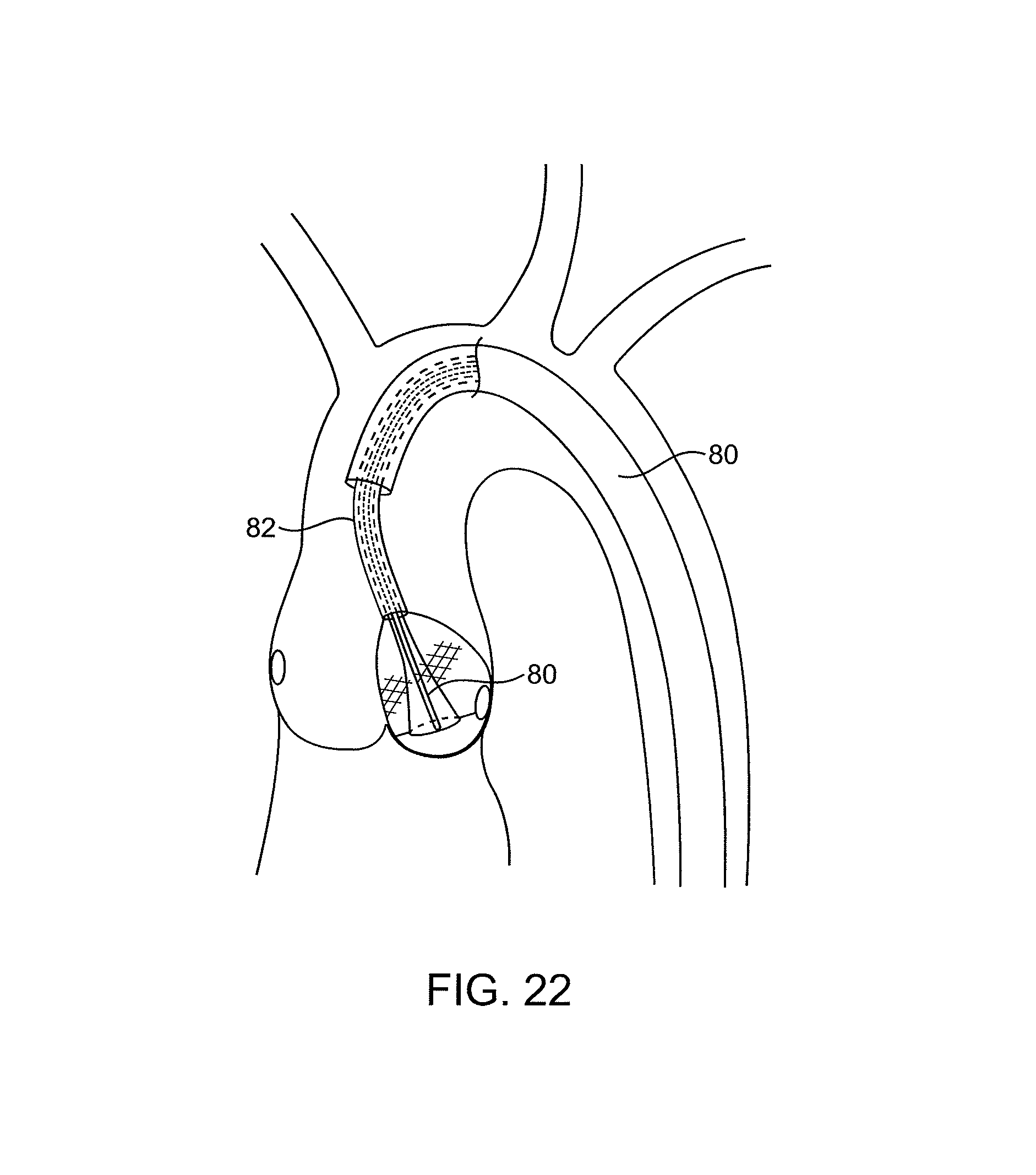
D00015
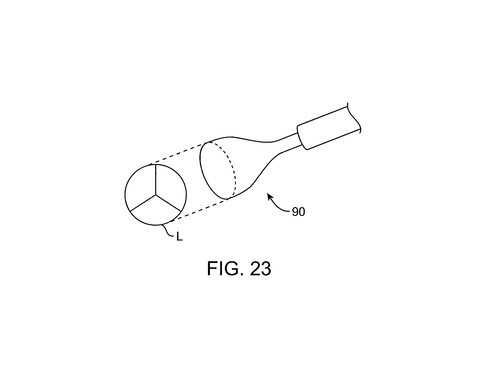
D00016
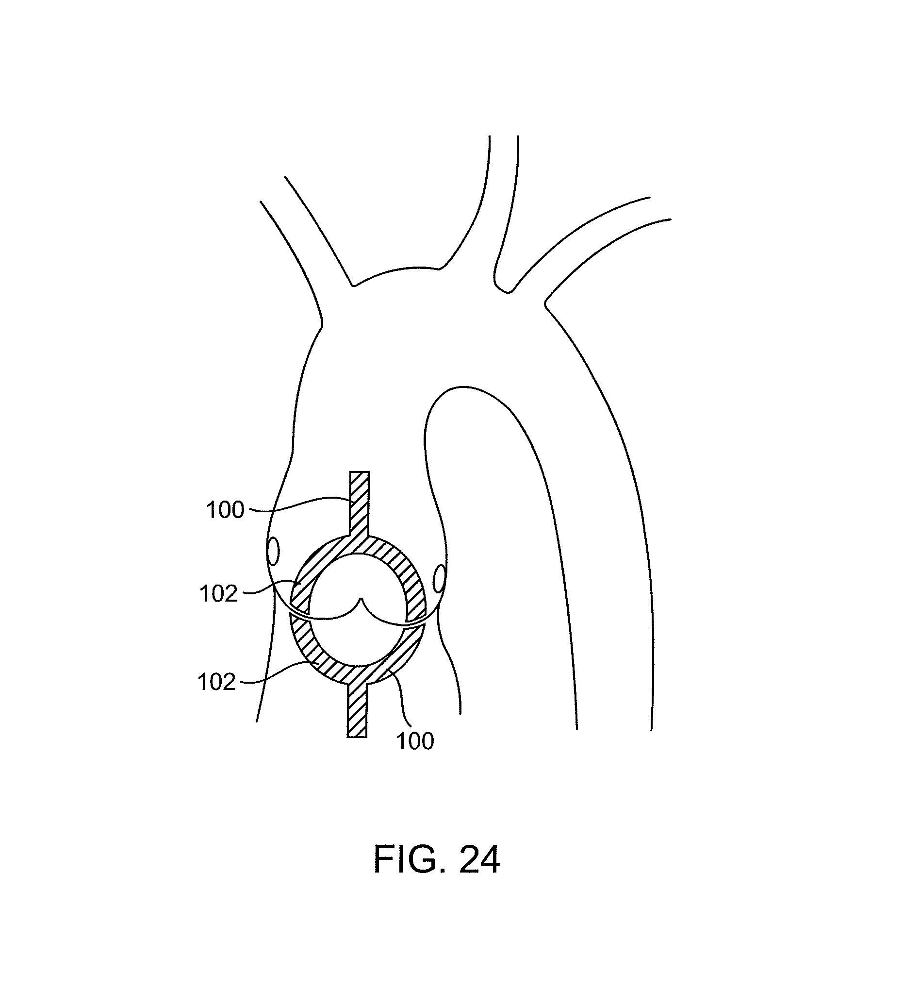
D00017
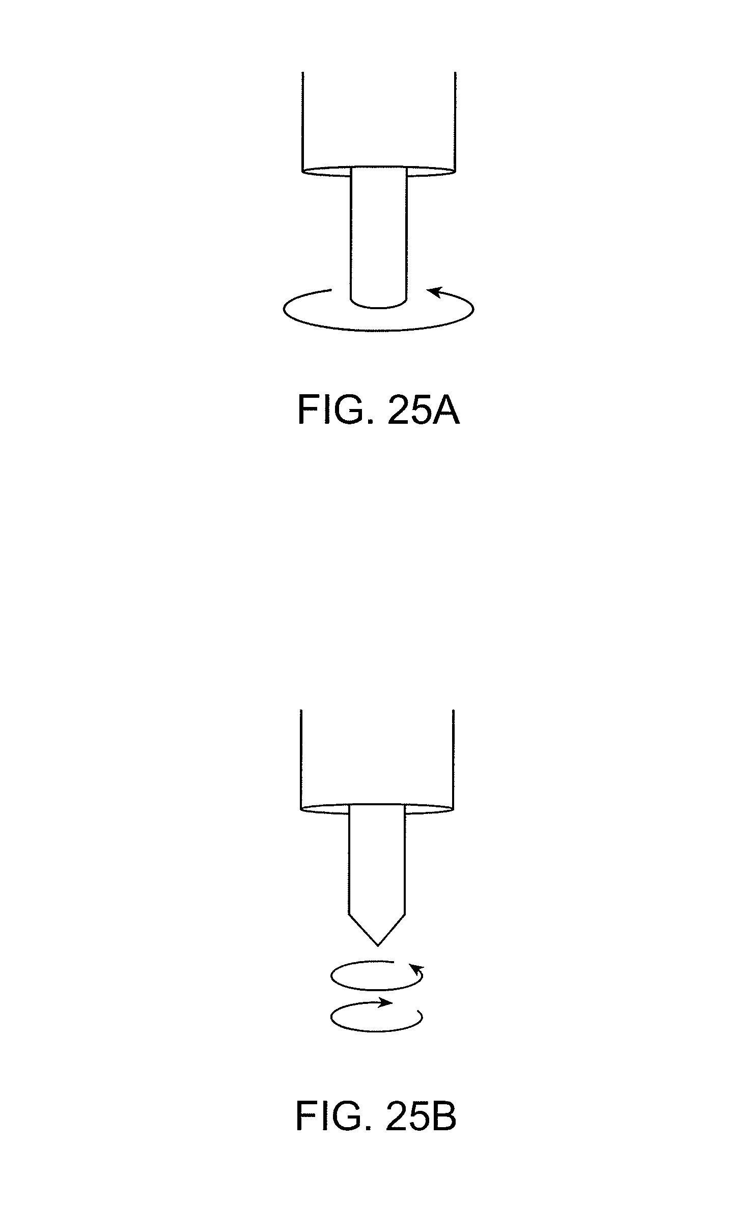
D00018

D00019
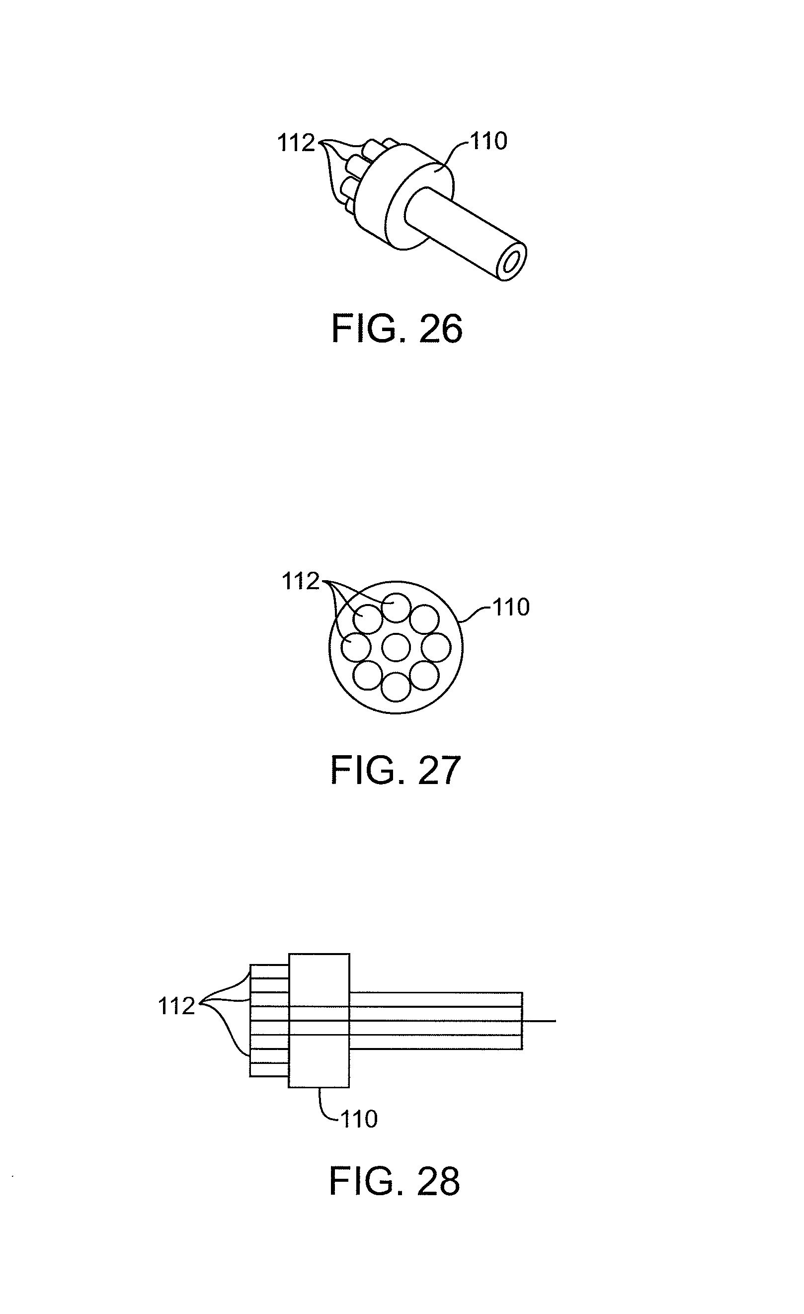
D00020

D00021
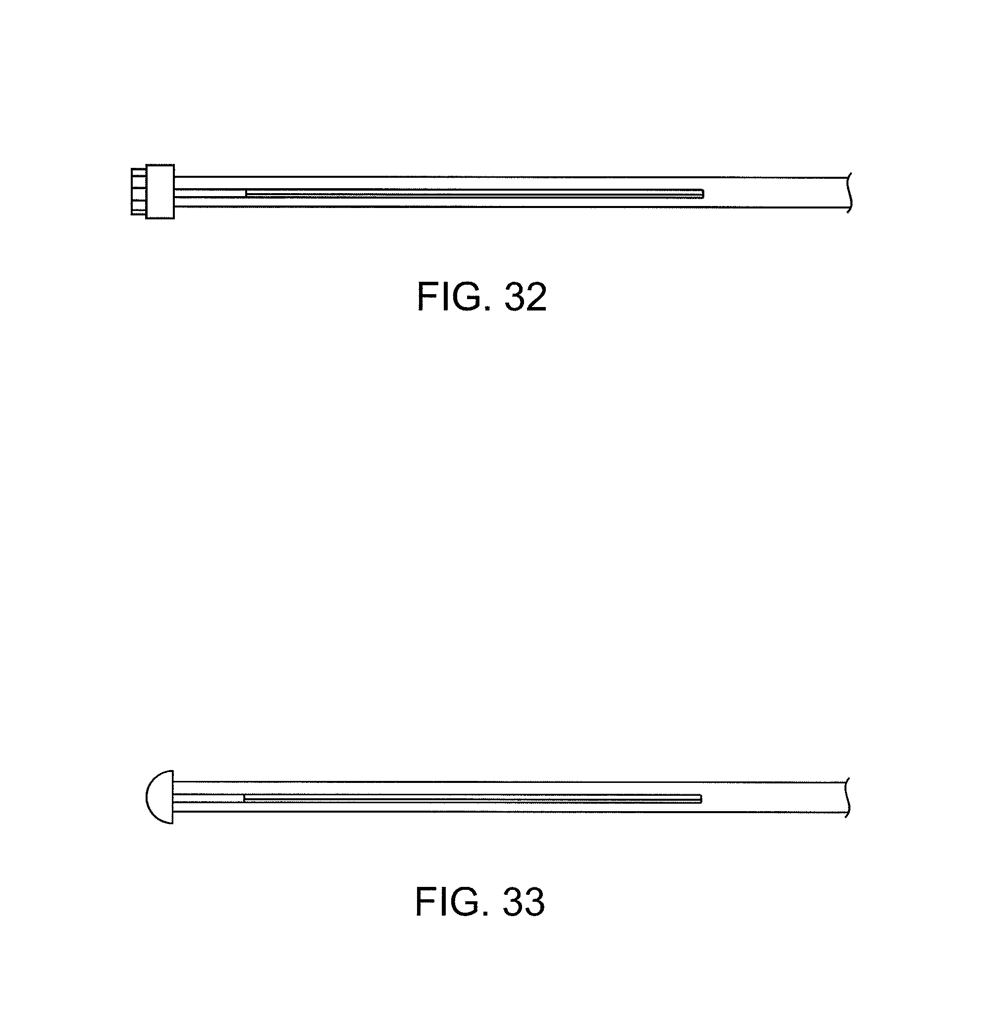
D00022

D00023
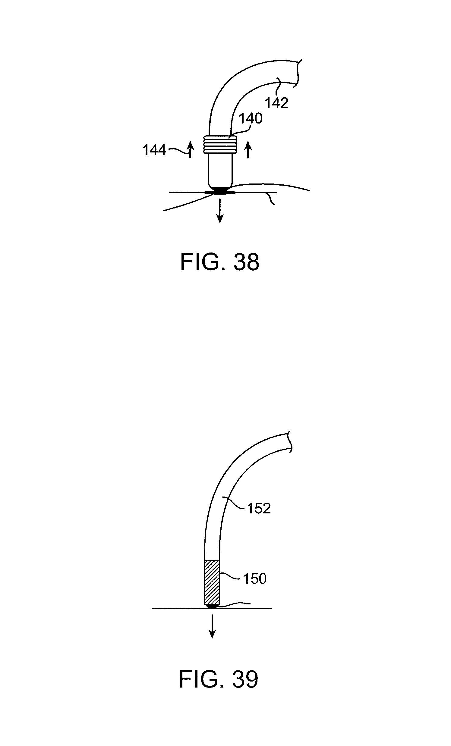
D00024

D00025

D00026
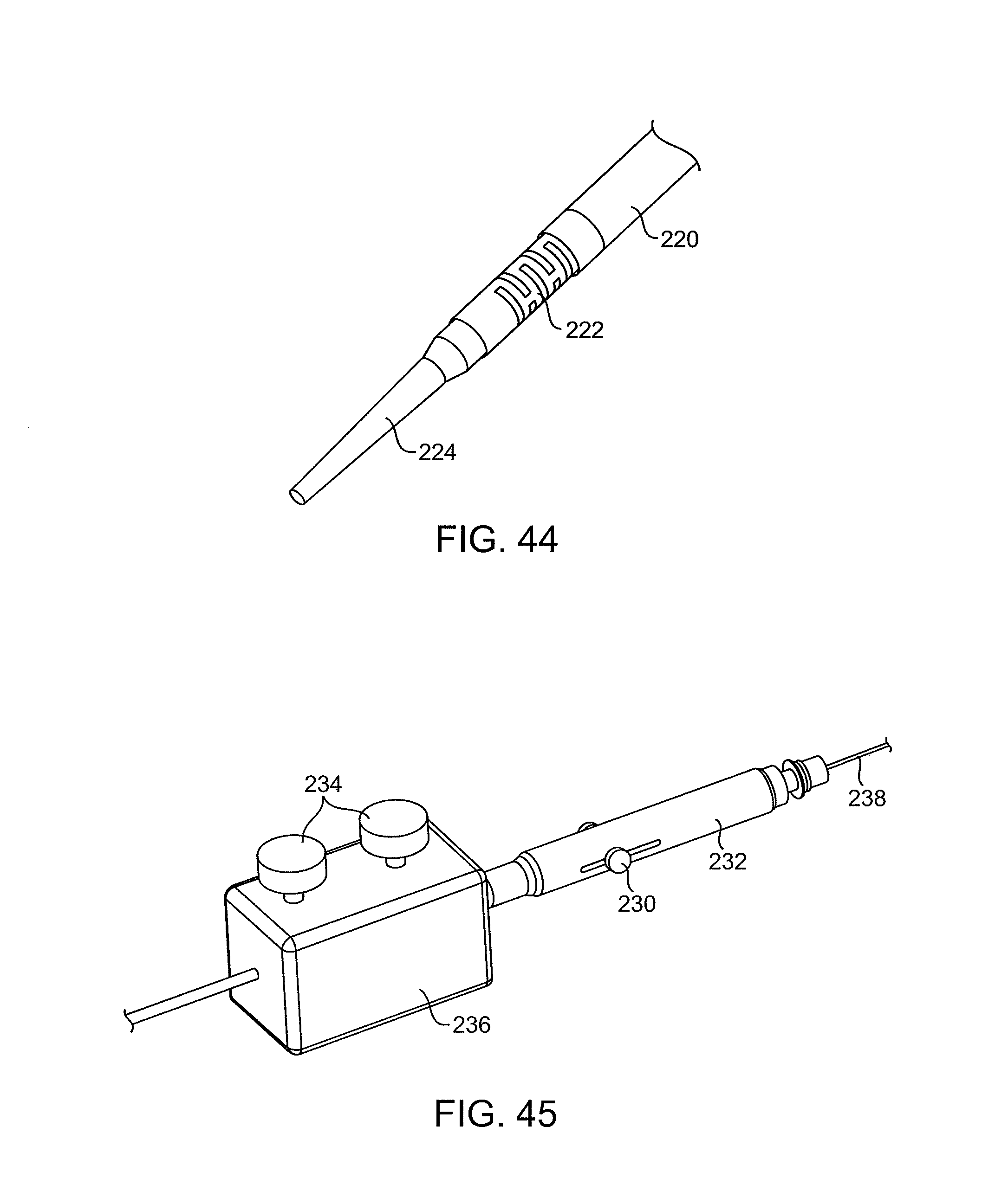
D00027
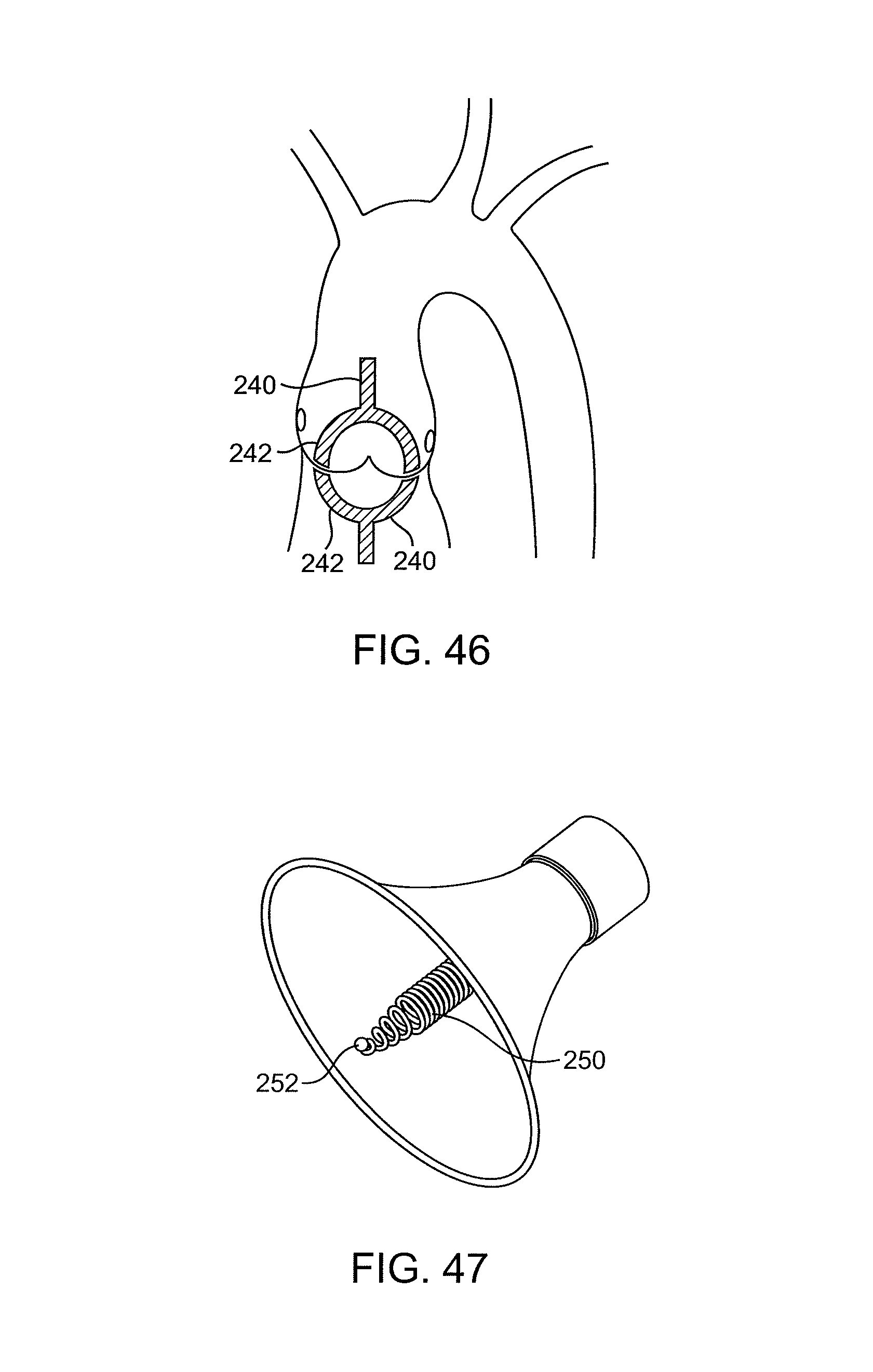
D00028

D00029
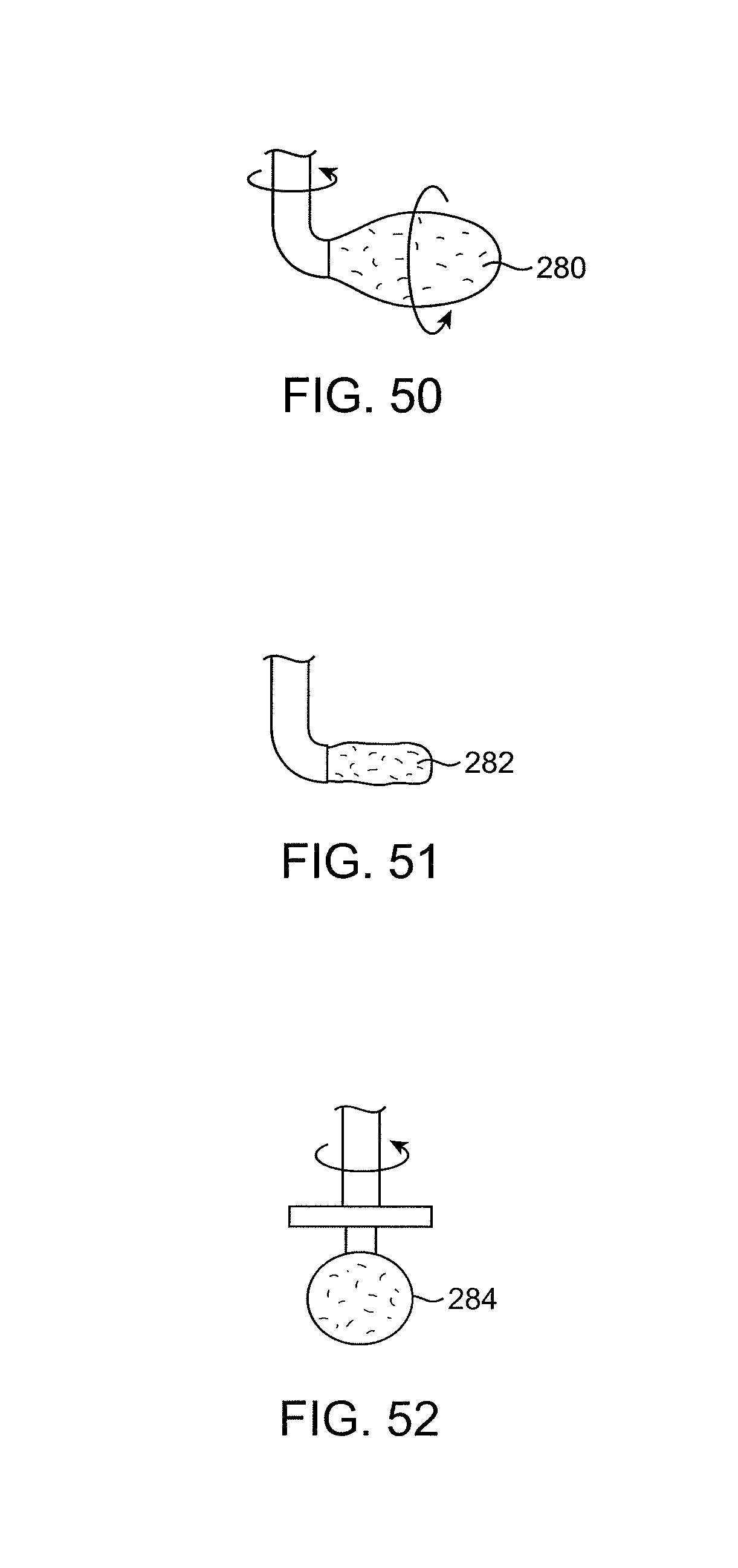
D00030
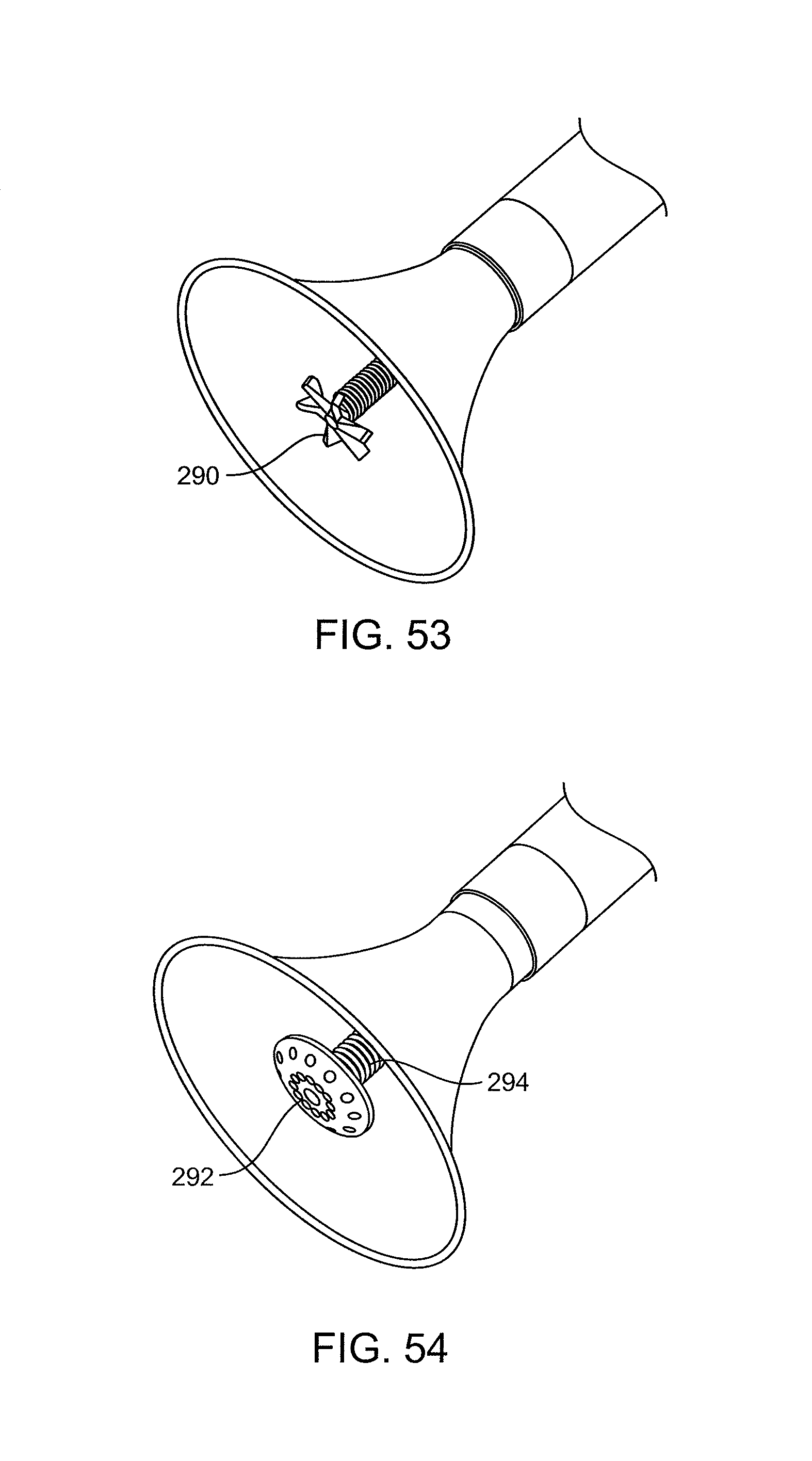
D00031
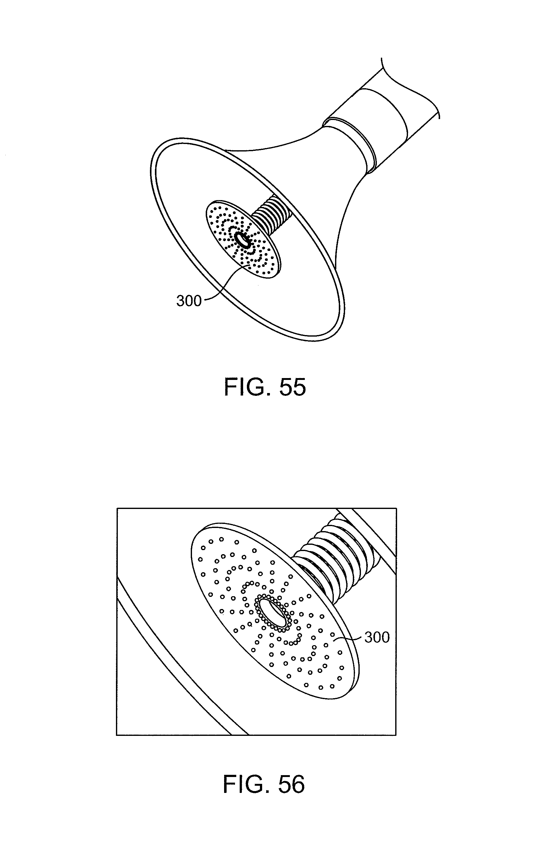
D00032
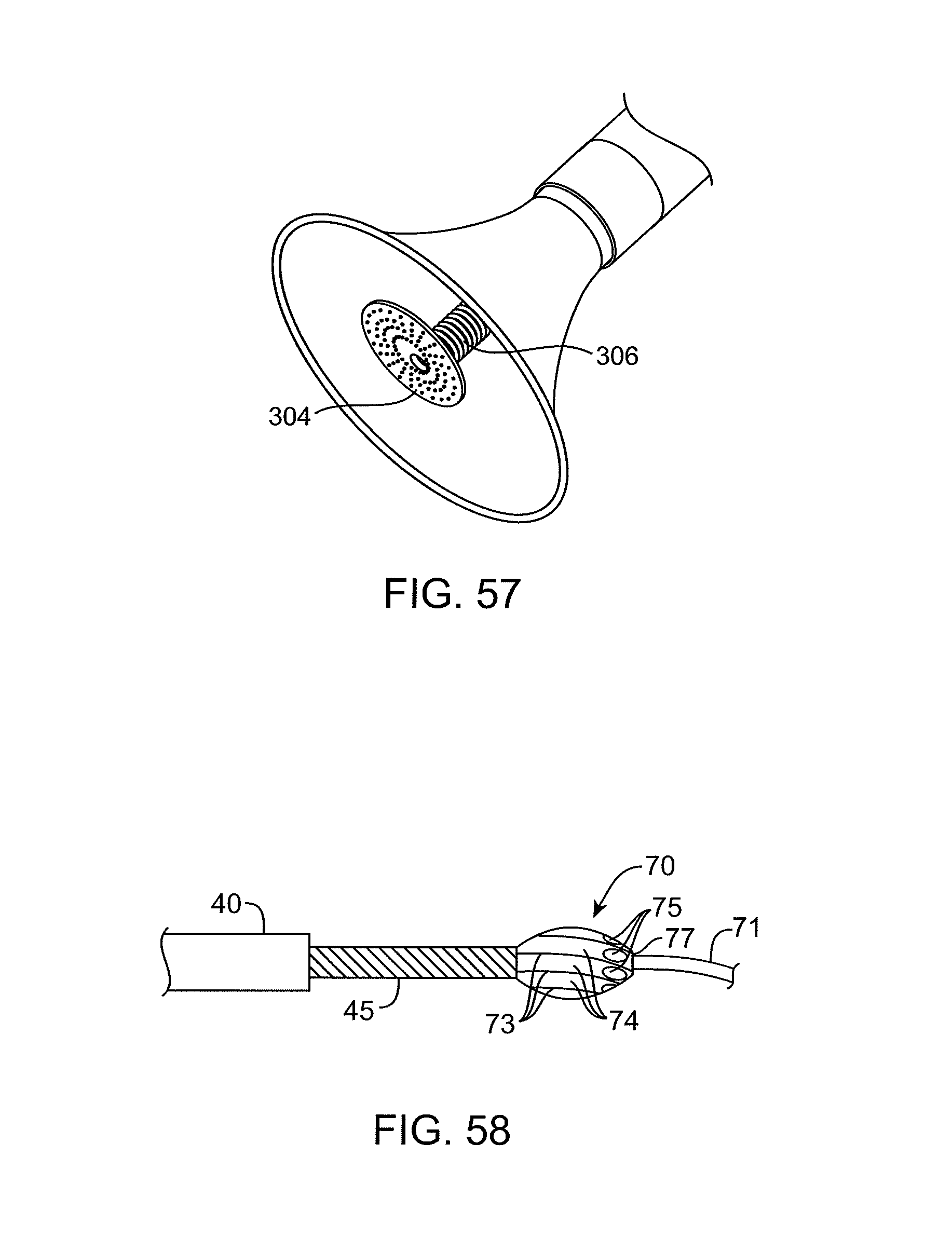
D00033

D00034

D00035
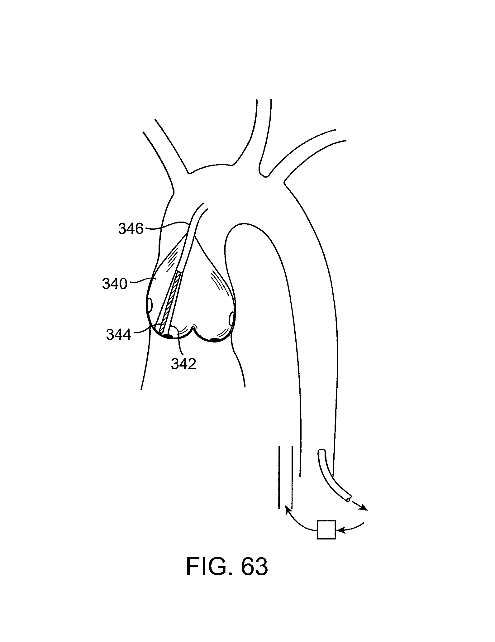
D00036
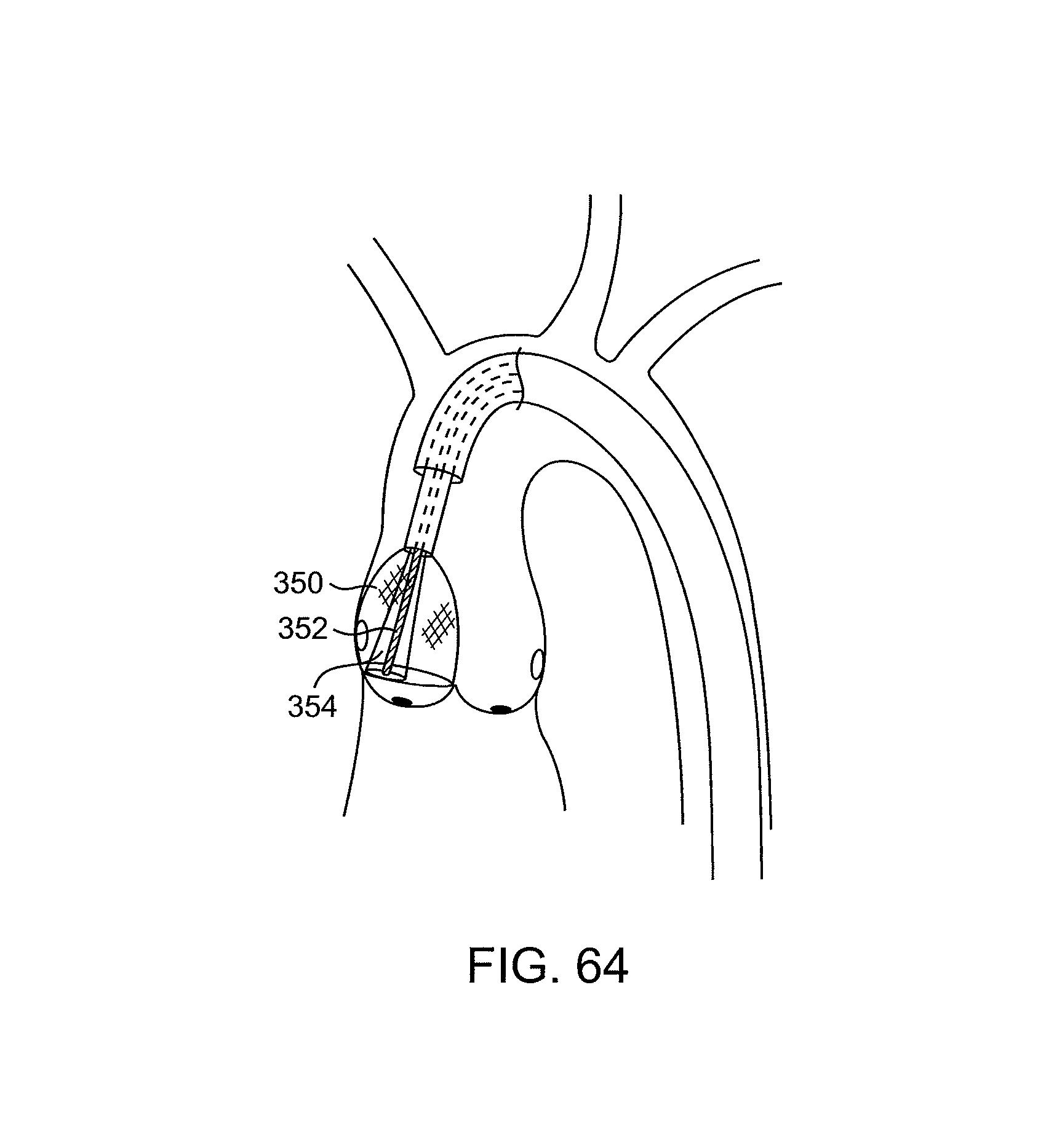
D00037
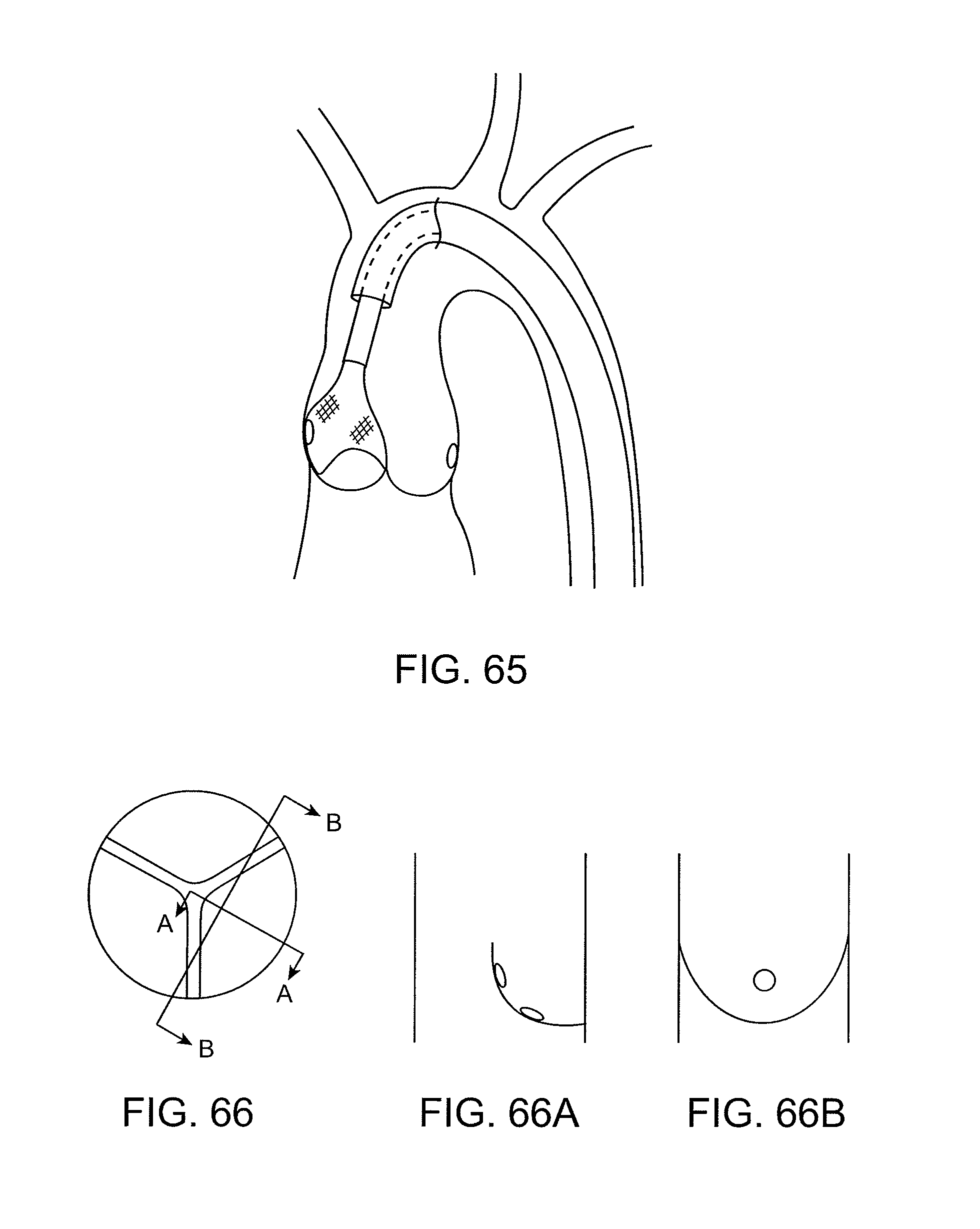
D00038

D00039
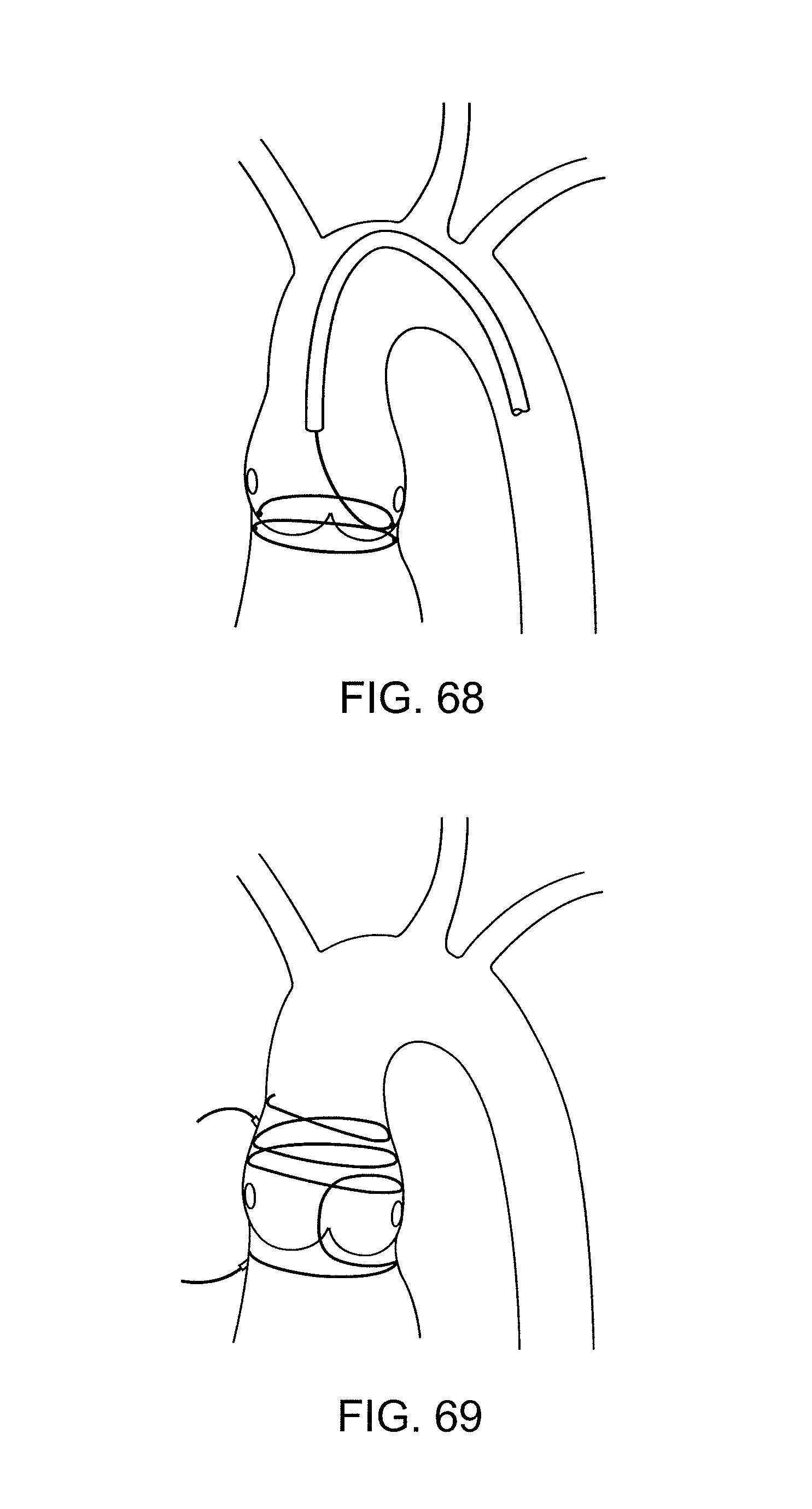
D00040

D00041

D00042

D00043
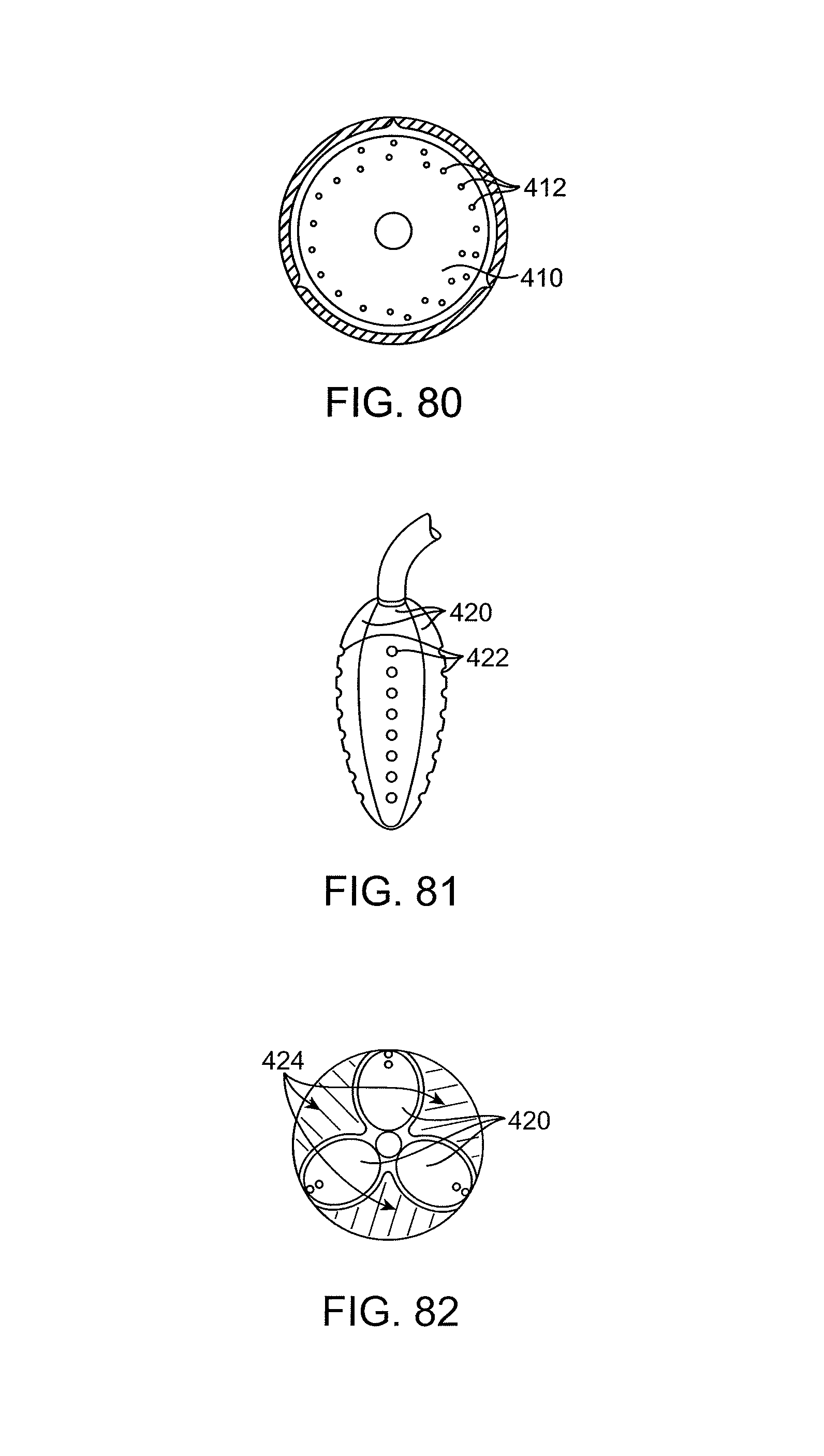
D00044

D00045

D00046
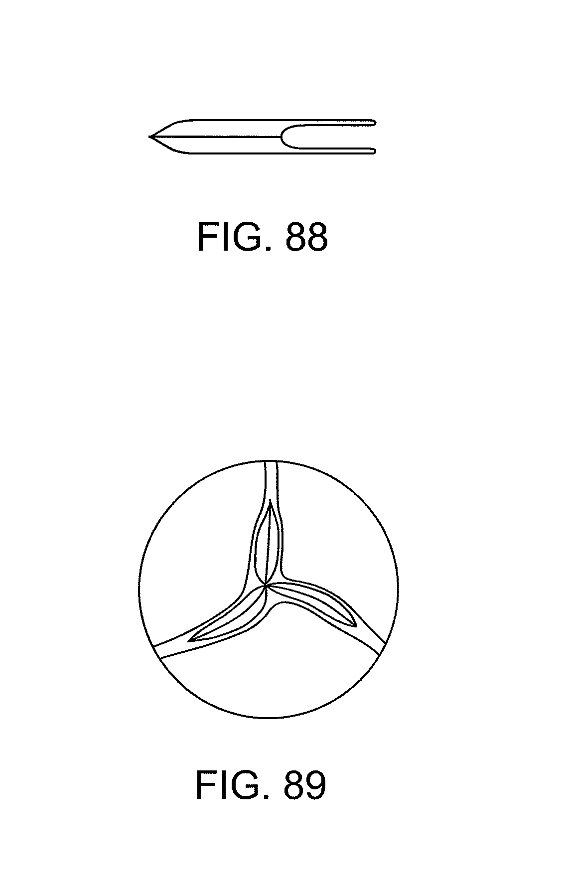
XML
uspto.report is an independent third-party trademark research tool that is not affiliated, endorsed, or sponsored by the United States Patent and Trademark Office (USPTO) or any other governmental organization. The information provided by uspto.report is based on publicly available data at the time of writing and is intended for informational purposes only.
While we strive to provide accurate and up-to-date information, we do not guarantee the accuracy, completeness, reliability, or suitability of the information displayed on this site. The use of this site is at your own risk. Any reliance you place on such information is therefore strictly at your own risk.
All official trademark data, including owner information, should be verified by visiting the official USPTO website at www.uspto.gov. This site is not intended to replace professional legal advice and should not be used as a substitute for consulting with a legal professional who is knowledgeable about trademark law.