Connector for securing ultrasound catheter to transducer
Nita , et al. July 16, 2
U.S. patent number 10,349,964 [Application Number 15/256,233] was granted by the patent office on 2019-07-16 for connector for securing ultrasound catheter to transducer. This patent grant is currently assigned to Flowcardia, Inc.. The grantee listed for this patent is Flowcardia, Inc.. Invention is credited to Henry Nita, Martinos Tran.


| United States Patent | 10,349,964 |
| Nita , et al. | July 16, 2019 |
Connector for securing ultrasound catheter to transducer
Abstract
An ultrasound system has an ultrasound transducer having a transducer housing and a horn provided at the distal end of the transducer housing, an ultrasound transmission member, a sonic connector that is connected to the horn and the proximal end of the ultrasound transmission member, and a catheter knob having a proximal end that is coupled to the distal end of the transducer housing. The catheter knob has a proximal bore that houses the sonic connector. The system also includes a nesting piece that is retained inside the proximal bore of the catheter knob. The nesting piece can be moved from a first position where the sonic connector is received inside the nesting piece to a second position where the sonic connector is separated from the nesting piece when ultrasound energy is being propagated through the ultrasound transmission member.
| Inventors: | Nita; Henry (Redwood Shores, CA), Tran; Martinos (Tracy, CA) | ||||||||||
|---|---|---|---|---|---|---|---|---|---|---|---|
| Applicant: |
|
||||||||||
| Assignee: | Flowcardia, Inc. (Franklin
Lakes, NJ) |
||||||||||
| Family ID: | 35481583 | ||||||||||
| Appl. No.: | 15/256,233 | ||||||||||
| Filed: | September 2, 2016 |
Prior Publication Data
| Document Identifier | Publication Date | |
|---|---|---|
| US 20160367284 A1 | Dec 22, 2016 | |
Related U.S. Patent Documents
| Application Number | Filing Date | Patent Number | Issue Date | ||
|---|---|---|---|---|---|
| 14169009 | Jan 30, 2014 | 9433433 | |||
| 12831883 | Jul 7, 2010 | 8641630 | |||
| 11192749 | Jul 29, 2005 | 7758510 | |||
| 10666459 | Sep 19, 2003 | 6942620 | |||
| Current U.S. Class: | 1/1 |
| Current CPC Class: | A61B 8/445 (20130101); A61B 8/12 (20130101); A61B 90/50 (20160201); A61B 17/320068 (20130101); A61B 2017/320069 (20170801); C08L 2201/12 (20130101); A61B 2017/00867 (20130101) |
| Current International Class: | A61B 8/00 (20060101); A61B 17/32 (20060101); A61B 8/12 (20060101); A61B 90/50 (20160101); A61B 17/00 (20060101) |
References Cited [Referenced By]
U.S. Patent Documents
| 3296620 | January 1967 | Rodda |
| 3433226 | March 1969 | Boyd |
| 3443226 | May 1969 | Knight |
| 3565062 | February 1971 | Kurls |
| 3585082 | June 1971 | Siller |
| 3612038 | October 1971 | Halligan |
| 3631848 | January 1972 | Muller |
| 3679378 | July 1972 | Van Impe et al. |
| 3719737 | March 1973 | Vaillancourt et al. |
| 3739460 | June 1973 | Addis et al. |
| 3754746 | August 1973 | Thiele |
| 3823717 | July 1974 | Pohlman et al. |
| 3835690 | September 1974 | Leonhardt et al. |
| 3839841 | October 1974 | Amplatz |
| 3896811 | July 1975 | Storz |
| 4016882 | April 1977 | Broadwin et al. |
| 4033331 | July 1977 | Guss et al. |
| 4136700 | January 1979 | Broadwin et al. |
| 4337090 | June 1982 | Harrison |
| 4368410 | January 1983 | Hance et al. |
| 4417578 | November 1983 | Banko |
| 4425115 | January 1984 | Wuchinich |
| 4453935 | June 1984 | Newton |
| 4486680 | December 1984 | Bonnet et al. |
| 4495232 | January 1985 | Bauser et al. |
| 4505767 | March 1985 | Quin |
| 4535759 | August 1985 | Polk et al. |
| 4545767 | October 1985 | Suzuki et al. |
| 4565589 | January 1986 | Harrison |
| 4565787 | January 1986 | Bossle et al. |
| 4572184 | February 1986 | Stohl et al. |
| 4664112 | May 1987 | Kensey et al. |
| 4665906 | May 1987 | Jervis |
| 4679558 | July 1987 | Kensey et al. |
| 4700705 | October 1987 | Kensey et al. |
| 4721117 | January 1988 | Mar et al. |
| 4750902 | June 1988 | Wuchinich et al. |
| 4781186 | November 1988 | Simpson et al. |
| 4808153 | February 1989 | Parisi |
| 4811743 | March 1989 | Stevens |
| 4827911 | May 1989 | Broadwin et al. |
| 4838853 | June 1989 | Parisi |
| 4854325 | August 1989 | Stevens |
| 4870953 | October 1989 | DonMicheal et al. |
| 4886060 | December 1989 | Wiksell |
| 4920954 | May 1990 | Alliger et al. |
| 4923462 | May 1990 | Stevens |
| 4924863 | May 1990 | Sterzer |
| 4931047 | June 1990 | Broadwin et al. |
| 4936281 | June 1990 | Stasz |
| 4936845 | June 1990 | Stevens |
| 4979952 | December 1990 | Kubota et al. |
| 5000185 | March 1991 | Yock |
| 5015227 | May 1991 | Broadwin et al. |
| 5026384 | June 1991 | Farr et al. |
| 5030201 | July 1991 | Palestrant |
| 5030357 | July 1991 | Lowe |
| 5046503 | September 1991 | Schneiderman |
| 5053008 | October 1991 | Bajaj |
| 5058570 | October 1991 | Idemoto et al. |
| 5076276 | December 1991 | Sakurai et al. |
| 5091205 | February 1992 | Fan |
| 5100423 | March 1992 | Fearnot |
| 5109859 | May 1992 | Jenkins |
| 5114414 | May 1992 | Buchbinder |
| 5116350 | May 1992 | Stevens |
| 5127917 | July 1992 | Niederhauser et al. |
| 5131393 | July 1992 | Ishiguro et al. |
| 5156143 | October 1992 | Bocquet et al. |
| 5163421 | November 1992 | Bernstein et al. |
| 5171216 | December 1992 | Dasse et al. |
| 5180363 | January 1993 | Idemoto et al. |
| 5183470 | February 1993 | Wettermann |
| 5195955 | March 1993 | Don Michael |
| 5215614 | June 1993 | Wijkamp et al. |
| 5217565 | June 1993 | Kou et al. |
| 5221255 | June 1993 | Mahurkar et al. |
| 5226421 | July 1993 | Frisbie et al. |
| 5234416 | August 1993 | Macaulay et al. |
| 5236414 | August 1993 | Takasu |
| 5238004 | August 1993 | Sahatjian et al. |
| 5242385 | September 1993 | Strukel |
| 5243997 | September 1993 | Uflacker et al. |
| 5248296 | September 1993 | Alliger |
| 5255669 | October 1993 | Kubota et al. |
| 5267954 | December 1993 | Nita |
| 5269291 | December 1993 | Carter |
| 5269297 | December 1993 | Weng et al. |
| 5269793 | December 1993 | Simpson |
| 5279546 | January 1994 | Mische et al. |
| 5287858 | February 1994 | Hammerslag et al. |
| 5290229 | March 1994 | Paskar |
| 5304115 | April 1994 | Pflueger et al. |
| 5304131 | April 1994 | Paskar |
| 5312328 | May 1994 | Nita et al. |
| 5318014 | June 1994 | Carter |
| 5318570 | June 1994 | Hood et al. |
| 5324255 | June 1994 | Passafaro et al. |
| 5324260 | June 1994 | O'Neill et al. |
| 5325860 | July 1994 | Seward et al. |
| 5326342 | July 1994 | Pflueger et al. |
| 5328004 | July 1994 | Fannin et al. |
| 5329927 | July 1994 | Gardineer et al. |
| 5341818 | August 1994 | Abrams et al. |
| 5342292 | August 1994 | Nita et al. |
| 5344395 | September 1994 | Whalen et al. |
| 5346502 | September 1994 | Estabrook et al. |
| 5362309 | November 1994 | Carter |
| 5368557 | November 1994 | Nita |
| 5368558 | November 1994 | Nita et al. |
| 5376084 | December 1994 | Bacich et al. |
| 5378234 | January 1995 | Hammerslag et al. |
| 5380274 | January 1995 | Nita |
| 5380316 | January 1995 | Aita et al. |
| 5382228 | January 1995 | Nita et al. |
| 5383460 | January 1995 | Jang |
| 5389096 | February 1995 | Aita et al. |
| 5391144 | February 1995 | Sakurai et al. |
| 5397293 | March 1995 | Alliger et al. |
| 5397301 | March 1995 | Pflueger et al. |
| 5403324 | April 1995 | Ciervo et al. |
| 5405318 | April 1995 | Nita |
| 5409483 | April 1995 | Campbell et al. |
| 5417672 | May 1995 | Nita et al. |
| 5417703 | May 1995 | Brown et al. |
| 5421923 | June 1995 | Clarke et al. |
| 5427118 | June 1995 | Nita et al. |
| 5431168 | July 1995 | Webster, Jr. |
| 5431663 | July 1995 | Carter |
| 5443078 | August 1995 | Uflacker |
| 5447509 | September 1995 | Mills et al. |
| 5449369 | September 1995 | Imran |
| 5449370 | September 1995 | Vaitekunas |
| 5451209 | September 1995 | Ainsworth et al. |
| 5462529 | October 1995 | Simpson et al. |
| 5465733 | November 1995 | Hinohara et al. |
| 5474530 | December 1995 | Passafaro et al. |
| 5474531 | December 1995 | Carter |
| 5480379 | January 1996 | La Rosa |
| 5484398 | January 1996 | Stoddard |
| 5487757 | January 1996 | Truckai et al. |
| 5498236 | March 1996 | Dubrul et al. |
| 5507738 | April 1996 | Ciervo |
| 5516043 | May 1996 | Manna et al. |
| 5527273 | June 1996 | Manna et al. |
| 5538512 | July 1996 | Zenzon et al. |
| 5540656 | July 1996 | Pflueger et al. |
| 5542917 | August 1996 | Nita et al. |
| 5597497 | January 1997 | Dean et al. |
| 5597882 | January 1997 | Schiller et al. |
| 5607421 | March 1997 | Jeevanandam et al. |
| 5611807 | March 1997 | O'Boyle |
| 5618266 | April 1997 | Liprie |
| 5626593 | May 1997 | Imran |
| 5627365 | May 1997 | Chiba et al. |
| 5649935 | July 1997 | Kremer et al. |
| 5658282 | August 1997 | Daw et al. |
| 5665062 | September 1997 | Houser |
| 5685841 | November 1997 | Mackool |
| 5695460 | December 1997 | Siegel et al. |
| 5695507 | December 1997 | Auth et al. |
| 5715825 | February 1998 | Crowley |
| 5720724 | February 1998 | Ressemann et al. |
| 5725494 | March 1998 | Brisken |
| 5728062 | March 1998 | Brisken |
| 5738100 | April 1998 | Yagami et al. |
| 5797876 | August 1998 | Spears et al. |
| 5816923 | October 1998 | Milo et al. |
| 5827203 | October 1998 | Nita |
| 5827971 | October 1998 | Hale et al. |
| 5830127 | November 1998 | DeCastro |
| 5830222 | November 1998 | Makower |
| 5846218 | December 1998 | Brisken et al. |
| 5873835 | February 1999 | Hastings et al. |
| 5876385 | March 1999 | Ikari et al. |
| 5893838 | April 1999 | Daoud et al. |
| 5895397 | April 1999 | Jang et al. |
| 5902287 | May 1999 | Martin |
| 5904667 | May 1999 | Falwell |
| 5916192 | June 1999 | Nita et al. |
| 5916912 | June 1999 | Ames et al. |
| 5935142 | August 1999 | Hood |
| 5935144 | August 1999 | Estabrook |
| 5937301 | August 1999 | Gardner et al. |
| 5944737 | August 1999 | Tsonton et al. |
| 5957882 | September 1999 | Nita et al. |
| 5957899 | September 1999 | Spears et al. |
| 5964223 | October 1999 | Baran |
| 5967984 | October 1999 | Chu et al. |
| 5971949 | October 1999 | Levin et al. |
| 5976119 | November 1999 | Spears et al. |
| 5989208 | November 1999 | Nita |
| 5989275 | November 1999 | Estabrook et al. |
| 5997497 | December 1999 | Nita et al. |
| 6004280 | December 1999 | Buck et al. |
| 6004335 | December 1999 | Vaitekunas et al. |
| 6007499 | December 1999 | Martin et al. |
| 6007514 | December 1999 | Nita |
| 6022309 | February 2000 | Celliers et al. |
| 6024764 | February 2000 | Schroeppel |
| 6029671 | February 2000 | Stevens et al. |
| 6030357 | February 2000 | Daoud |
| 6036689 | March 2000 | Tu et al. |
| 6051010 | April 2000 | DiMatteo et al. |
| 6066135 | May 2000 | Honda |
| 6113558 | September 2000 | Rosenschein et al. |
| 6120515 | September 2000 | Rogers et al. |
| 6123698 | September 2000 | Spears et al. |
| 6142971 | November 2000 | Daoud et al. |
| 6149596 | November 2000 | Bancroft |
| 6159176 | December 2000 | Broadwin et al. |
| 6159187 | December 2000 | Park et al. |
| 6165127 | December 2000 | Crowley |
| 6165188 | December 2000 | Saadat et al. |
| 6179809 | January 2001 | Khairkhahan et al. |
| 6180059 | January 2001 | Divino, Jr. et al. |
| 6190353 | February 2001 | Makower et al. |
| 6206842 | March 2001 | Tu et al. |
| 6210356 | April 2001 | Anderson et al. |
| 6217543 | April 2001 | Anis et al. |
| 6217565 | April 2001 | Cohen |
| 6217588 | April 2001 | Jerger et al. |
| 6221015 | April 2001 | Yock |
| 6231546 | May 2001 | Milo et al. |
| 6231587 | May 2001 | Makower |
| 6235007 | May 2001 | Divino, Jr. et al. |
| 6241692 | June 2001 | Tu et al. |
| 6241703 | June 2001 | Levin et al. |
| 6241744 | June 2001 | Imran et al. |
| 6248087 | June 2001 | Spears et al. |
| 6277084 | August 2001 | Abele et al. |
| 6283983 | September 2001 | Makower et al. |
| 6287271 | September 2001 | Dubrul et al. |
| 6287285 | September 2001 | Michal et al. |
| 6287317 | September 2001 | Makower et al. |
| 6296620 | October 2001 | Gesswein et al. |
| 6298620 | October 2001 | Hatzinikolas |
| 6302875 | October 2001 | Makower et al. |
| 6309358 | October 2001 | Okubo |
| 6315741 | November 2001 | Martin et al. |
| 6315754 | November 2001 | Daoud et al. |
| 6331171 | December 2001 | Cohen |
| 6346192 | February 2002 | Buhr et al. |
| 6379378 | April 2002 | Werneth et al. |
| 6387109 | May 2002 | Davison et al. |
| 6387324 | May 2002 | Patterson et al. |
| 6394956 | May 2002 | Chandrasekaran et al. |
| 6398736 | June 2002 | Seward |
| 6409673 | June 2002 | Yock |
| 6416533 | July 2002 | Gobin et al. |
| 6423026 | July 2002 | Gesswein et al. |
| 6427118 | July 2002 | Suzuki |
| 6433464 | August 2002 | Jones |
| 6434418 | August 2002 | Neal et al. |
| 6450975 | September 2002 | Brennan et al. |
| 6454737 | September 2002 | Nita et al. |
| 6454757 | September 2002 | Nita et al. |
| 6454997 | September 2002 | Divino, Jr. et al. |
| 6484052 | November 2002 | Visuri et al. |
| 6491707 | December 2002 | Makower et al. |
| 6494891 | December 2002 | Cornish et al. |
| 6494894 | December 2002 | Mirarchi |
| 6500141 | December 2002 | Irion et al. |
| 6508781 | January 2003 | Brennan et al. |
| 6508784 | January 2003 | Shu |
| 6511458 | January 2003 | Milo et al. |
| 6514249 | February 2003 | Maguire et al. |
| 6524251 | February 2003 | Rabiner et al. |
| 6533766 | March 2003 | Patterson et al. |
| 6544215 | April 2003 | Bencini et al. |
| 6547754 | April 2003 | Evans et al. |
| 6547788 | April 2003 | Maguire et al. |
| 6551337 | April 2003 | Rabiner et al. |
| 6554846 | April 2003 | Hamilton et al. |
| 6555059 | April 2003 | Myrick et al. |
| 6558502 | May 2003 | Divino, Jr. et al. |
| 6562031 | May 2003 | Chandrasekaran et al. |
| 6573470 | June 2003 | Brown et al. |
| 6576807 | June 2003 | Brunelot et al. |
| 6582387 | June 2003 | Derek et al. |
| 6589253 | July 2003 | Cornish et al. |
| 6595989 | July 2003 | Schaer |
| 6596235 | July 2003 | Divino, Jr. et al. |
| 6602467 | August 2003 | Divino, Jr. et al. |
| 6602468 | August 2003 | Patterson et al. |
| 6605217 | August 2003 | Buhr et al. |
| 6607698 | August 2003 | Spears et al. |
| 6610077 | August 2003 | Hancock et al. |
| 6613280 | September 2003 | Myrick et al. |
| 6615062 | September 2003 | Ryan et al. |
| 6616617 | September 2003 | Ferrera et al. |
| 6622542 | September 2003 | Derek et al. |
| 6623448 | September 2003 | Slater |
| 6635017 | October 2003 | Moehring et al. |
| 6650923 | November 2003 | Lesh et al. |
| 6652547 | November 2003 | Rabiner et al. |
| 6660013 | December 2003 | Rabiner et al. |
| 6676900 | January 2004 | Divino, Jr. et al. |
| 6682502 | January 2004 | Bond et al. |
| 6685657 | February 2004 | Jones |
| 6689086 | February 2004 | Nita et al. |
| 6695781 | February 2004 | Rabiner et al. |
| 6695782 | February 2004 | Ranucci et al. |
| 6695810 | February 2004 | Peacock, III et al. |
| 6702748 | March 2004 | Nita et al. |
| 6702750 | March 2004 | Yock |
| 6719715 | April 2004 | Newman et al. |
| 6719725 | April 2004 | Milo et al. |
| 6729334 | May 2004 | Baran |
| 6733451 | May 2004 | Rabiner et al. |
| 6758846 | July 2004 | Goble et al. |
| 6761698 | July 2004 | Shibata et al. |
| 6814727 | November 2004 | Mansouri-Ruiz |
| 6855123 | February 2005 | Nita |
| 6866670 | March 2005 | Rabiner et al. |
| 6936025 | August 2005 | Evans et al. |
| 6936056 | August 2005 | Nash et al. |
| 6942620 | September 2005 | Nita |
| 6942677 | September 2005 | Nita et al. |
| 6955680 | October 2005 | Satou et al. |
| 7004173 | February 2006 | Sparks et al. |
| 7004176 | February 2006 | Lau |
| 7056294 | June 2006 | Khairkhahan et al. |
| 7131983 | November 2006 | Murakami |
| 7137963 | November 2006 | Nita et al. |
| 7149587 | December 2006 | Wardle et al. |
| 7150853 | December 2006 | Lee et al. |
| 7166098 | January 2007 | Steward et al. |
| 7220233 | May 2007 | Nita et al. |
| 7267650 | September 2007 | Chow et al. |
| 7297131 | November 2007 | Nita |
| 7335180 | February 2008 | Nita et al. |
| 7341569 | March 2008 | Soltani et al. |
| 7384407 | June 2008 | Rodriguez et al. |
| 7393338 | July 2008 | Nita |
| 7421900 | September 2008 | Karasawa et al. |
| 7425198 | September 2008 | Moehring et al. |
| 7494468 | February 2009 | Rabiner et al. |
| 7503895 | March 2009 | Rabiner et al. |
| 7540852 | June 2009 | Nita et al. |
| 7604608 | October 2009 | Nita et al. |
| 7621902 | November 2009 | Nita et al. |
| 7621929 | November 2009 | Nita et al. |
| 7628763 | December 2009 | Noriega et al. |
| 7648478 | January 2010 | Soltani et al. |
| 7758510 | July 2010 | Nita |
| 7771358 | August 2010 | Moehring et al. |
| 7771452 | August 2010 | Pal et al. |
| 7775994 | August 2010 | Lockhart |
| 7776025 | August 2010 | Bobo, Jr. |
| 7819013 | October 2010 | Chan et al. |
| 7850623 | December 2010 | Griffin et al. |
| 7918819 | April 2011 | Karmarkar et al. |
| 7935108 | May 2011 | Baxter et al. |
| 7938819 | May 2011 | Kugler et al. |
| 7942809 | May 2011 | Leban |
| 7955293 | June 2011 | Nita et al. |
| 7993308 | August 2011 | Rule et al. |
| 8038693 | October 2011 | Allen |
| 8043251 | October 2011 | Nita et al. |
| 8052607 | November 2011 | Byrd |
| 8083727 | December 2011 | Kugler et al. |
| 8133236 | March 2012 | Nita |
| 8152753 | April 2012 | Nita et al. |
| 8172758 | May 2012 | Harhen |
| 8221343 | July 2012 | Nita et al. |
| 8226566 | July 2012 | Nita |
| 8246643 | August 2012 | Nita |
| 8257378 | September 2012 | O'connor |
| 8308677 | November 2012 | Nita et al. |
| 8343134 | January 2013 | Kost et al. |
| 8414543 | April 2013 | Mcguckin, Jr. et al. |
| 8496669 | July 2013 | Nita et al. |
| 8506519 | August 2013 | Nita |
| 8613700 | December 2013 | Ueno et al. |
| 8613751 | December 2013 | Nita et al. |
| 8617096 | December 2013 | Nita et al. |
| 8632560 | January 2014 | Pal et al. |
| 8641630 | February 2014 | Nita |
| 8647293 | February 2014 | Nita |
| 8647296 | February 2014 | Moberg et al. |
| 8663259 | March 2014 | Levine et al. |
| 8668709 | March 2014 | Nita et al. |
| 8690818 | April 2014 | Bennett et al. |
| 8690819 | April 2014 | Nita et al. |
| 8702595 | April 2014 | Ueki |
| 8708892 | April 2014 | Sugiyama et al. |
| 8708994 | April 2014 | Pettis et al. |
| 8725228 | May 2014 | Koblish et al. |
| 8764700 | July 2014 | Zhang et al. |
| 8768433 | July 2014 | Jenkins et al. |
| 8790291 | July 2014 | Nita et al. |
| 8974446 | March 2015 | Nguyen et al. |
| 8978478 | March 2015 | Ishioka |
| 9101387 | August 2015 | Plowe et al. |
| 9107590 | August 2015 | Hansmann et al. |
| 9237837 | January 2016 | Omoto et al. |
| 9265520 | February 2016 | Nita |
| 9282984 | March 2016 | Nita |
| 9314258 | April 2016 | Nita et al. |
| 9381027 | July 2016 | Nita et al. |
| 9421024 | August 2016 | Nita et al. |
| 9433433 | September 2016 | Nita |
| 9603615 | March 2017 | Sarge |
| 9770250 | September 2017 | Nita et al. |
| 9955994 | May 2018 | Nita |
| 10004520 | June 2018 | Nita et al. |
| 2002/0022858 | February 2002 | Demond et al. |
| 2002/0049409 | April 2002 | Noda et al. |
| 2002/0077550 | June 2002 | Rabiner et al. |
| 2002/0188276 | December 2002 | Evans et al. |
| 2002/0189357 | December 2002 | Lai et al. |
| 2003/0009153 | January 2003 | Brisken et al. |
| 2003/0036705 | February 2003 | Hare et al. |
| 2003/0040762 | February 2003 | Dorros et al. |
| 2003/0199817 | October 2003 | Thompson et al. |
| 2003/0216732 | November 2003 | Truckai et al. |
| 2003/0225332 | December 2003 | Okada et al. |
| 2004/0019349 | January 2004 | Fuimaono et al. |
| 2004/0024393 | February 2004 | Nita et al. |
| 2004/0054367 | March 2004 | Teodoro, Jr. et al. |
| 2004/0164030 | August 2004 | Lowe et al. |
| 2004/0167511 | August 2004 | Buehlmann et al. |
| 2004/0193033 | September 2004 | Badehi et al. |
| 2005/0033311 | February 2005 | Guldfeldt et al. |
| 2005/0149110 | July 2005 | Wholey et al. |
| 2005/0165388 | July 2005 | Bhola |
| 2005/0171527 | August 2005 | Bhola |
| 2005/0228286 | October 2005 | Messerly et al. |
| 2006/0074441 | April 2006 | Mcguckin, Jr. et al. |
| 2006/0149169 | July 2006 | Nunomura et al. |
| 2006/0206039 | September 2006 | Wilson et al. |
| 2006/0264809 | November 2006 | Hansmann et al. |
| 2007/0032749 | February 2007 | Overall et al. |
| 2007/0161945 | July 2007 | Nita et al. |
| 2007/0178768 | August 2007 | Harshrnan et al. |
| 2008/0033284 | February 2008 | Hauck |
| 2008/0071343 | March 2008 | Mayberry et al. |
| 2008/0208084 | August 2008 | Horzewski et al. |
| 2008/0221506 | September 2008 | Rodriguez et al. |
| 2008/0294037 | November 2008 | Richter |
| 2009/0017293 | January 2009 | Arai et al. |
| 2009/0143795 | June 2009 | Robertson |
| 2010/0004558 | January 2010 | Frankhouser et al. |
| 2010/0023037 | January 2010 | Nita et al. |
| 2010/0069854 | March 2010 | Okoh et al. |
| 2010/0076454 | March 2010 | Bos |
| 2010/0121144 | May 2010 | Farhadi |
| 2010/0217306 | August 2010 | Raabe et al. |
| 2010/0268206 | October 2010 | Manwaring et al. |
| 2011/0046522 | February 2011 | Chan et al. |
| 2011/0105960 | May 2011 | Wallace |
| 2011/0130834 | June 2011 | Wilson et al. |
| 2011/0196399 | August 2011 | Robertson et al. |
| 2011/0196403 | August 2011 | Robertson et al. |
| 2011/0237982 | September 2011 | Wallace |
| 2011/0313328 | December 2011 | Nita |
| 2012/0010506 | January 2012 | Ullrich |
| 2012/0109021 | May 2012 | Hastings et al. |
| 2012/0130475 | May 2012 | Shaw |
| 2012/0217306 | August 2012 | Morrill Webb et al. |
| 2012/0238916 | September 2012 | Nita et al. |
| 2012/0238946 | September 2012 | Nita et al. |
| 2012/0311844 | December 2012 | Nita et al. |
| 2012/0330196 | December 2012 | Nita |
| 2013/0046297 | February 2013 | Lingeman et al. |
| 2013/0060169 | March 2013 | Yamada |
| 2013/0331652 | December 2013 | Okamoto |
| 2013/0338580 | December 2013 | Yamatani et al. |
| 2014/0005706 | January 2014 | Gelfand et al. |
| 2014/0012087 | January 2014 | Omoto |
| 2014/0039491 | February 2014 | Bakos et al. |
| 2014/0171804 | June 2014 | Van Hoven |
| 2014/0224375 | August 2014 | Willis |
| 2014/0236118 | August 2014 | Unser et al. |
| 2014/0243712 | August 2014 | Humayun et al. |
| 2014/0350401 | November 2014 | Sinelnikov |
| 2014/0358028 | December 2014 | Vetter et al. |
| 2014/0358029 | December 2014 | Vetter et al. |
| 2015/0025544 | January 2015 | Nita et al. |
| 2015/0073357 | March 2015 | Bagwell et al. |
| 2015/0105621 | April 2015 | Farhadi |
| 2015/0105715 | April 2015 | Pikus et al. |
| 2015/0133918 | May 2015 | Sachar |
| 2015/0148795 | May 2015 | Amos et al. |
| 2015/0157443 | June 2015 | Hauser et al. |
| 2015/0190660 | July 2015 | Sarge et al. |
| 2015/0297258 | October 2015 | Escudero et al. |
| 2015/0359651 | December 2015 | Wubbeling |
| 2016/0128717 | May 2016 | Nita |
| 2016/0128767 | May 2016 | Azamian et al. |
| 2016/0135835 | May 2016 | Onuma |
| 2016/0183956 | June 2016 | Nita |
| 2016/0271362 | September 2016 | Van Liere |
| 2016/0328998 | November 2016 | Nita et al. |
| 2016/0338722 | November 2016 | Nita et al. |
| 2016/0367284 | December 2016 | Nita et al. |
| 2017/0065288 | March 2017 | Imai et al. |
| 2017/0128090 | May 2017 | Sarge |
| 2017/0265879 | September 2017 | Washburn, II et al. |
| 2017/0265886 | September 2017 | Nita et al. |
| 2017/0354428 | December 2017 | Nita et al. |
| 2018/0042636 | February 2018 | Nita |
| 2018/0140321 | May 2018 | Deepa |
| 2018/0168668 | June 2018 | Zheng |
| 2018/0177515 | June 2018 | Boyle et al. |
| 2018/0197856 | July 2018 | Chou et al. |
| 2018/0221040 | August 2018 | Roll Hoye |
| 2018/0280005 | October 2018 | Parmentier |
| 2018/0280044 | October 2018 | Nita et al. |
| 2007240154 | Jan 2008 | AU | |||
| 2256127 | May 1974 | DE | |||
| 2438648 | Feb 1976 | DE | |||
| 8910040 | Dec 1989 | DE | |||
| 3821836 | Jan 1990 | DE | |||
| 4042435 | Feb 1994 | DE | |||
| 10146011 | Apr 2003 | DE | |||
| 0005719 | Dec 1979 | EP | |||
| 0316789 | May 1989 | EP | |||
| 0316796 | May 1989 | EP | |||
| 0376562 | Jul 1990 | EP | |||
| 0379156 | Jul 1990 | EP | |||
| 0394583 | Oct 1990 | EP | |||
| 0443256 | Aug 1991 | EP | |||
| 0472368 | Feb 1992 | EP | |||
| 0541249 | May 1993 | EP | |||
| 0820728 | Jan 1998 | EP | |||
| 1323481 | Jul 2003 | EP | |||
| 1106957 | Mar 1968 | GB | |||
| H2-7150 | Oct 1988 | JP | |||
| 01-099547 | Apr 1989 | JP | |||
| 6086822 | Mar 1994 | JP | |||
| H07500752 | Jan 1995 | JP | |||
| 7116260 | May 1995 | JP | |||
| 9-503137 | Mar 1997 | JP | |||
| 10-216140 | Aug 1998 | JP | |||
| 2000-291543 | Oct 2000 | JP | |||
| 2001-104356 | Apr 2001 | JP | |||
| 2001-321388 | Nov 2001 | JP | |||
| 2002-186627 | Jul 2002 | JP | |||
| 2005-253874 | Sep 2005 | JP | |||
| 2006-522644 | Oct 2006 | JP | |||
| 2007512087 | May 2007 | JP | |||
| 2007520255 | Jul 2007 | JP | |||
| 8705739 | Sep 1987 | WO | |||
| 8705793 | Oct 1987 | WO | |||
| 8906515 | Jul 1989 | WO | |||
| 9001300 | Feb 1990 | WO | |||
| 9004362 | May 1990 | WO | |||
| 9107917 | Jun 1991 | WO | |||
| 9211815 | Jul 1992 | WO | |||
| 9308750 | May 1993 | WO | |||
| 9316646 | Sep 1993 | WO | |||
| 9412140 | Jun 1994 | WO | |||
| 9414382 | Jul 1994 | WO | |||
| 9508954 | Apr 1995 | WO | |||
| 9509571 | Apr 1995 | WO | |||
| 9515192 | Jun 1995 | WO | |||
| 9635469 | Nov 1996 | WO | |||
| 9705739 | Feb 1997 | WO | |||
| 9721462 | Jun 1997 | WO | |||
| 9745078 | Dec 1997 | WO | |||
| 9827874 | Jul 1998 | WO | |||
| 9835721 | Aug 1998 | WO | |||
| 9851224 | Nov 1998 | WO | |||
| 9852637 | Nov 1998 | WO | |||
| 9925412 | May 1999 | WO | |||
| 0053341 | Sep 2000 | WO | |||
| 0067830 | Nov 2000 | WO | |||
| 02094103 | Nov 2002 | WO | |||
| 03039381 | May 2003 | WO | |||
| 2004012609 | Feb 2004 | WO | |||
| 2004093736 | Nov 2004 | WO | |||
| 2004112888 | Dec 2004 | WO | |||
| 2005053769 | Jun 2005 | WO | |||
| 2005112770 | Dec 2005 | WO | |||
| 2006049593 | May 2006 | WO | |||
| 2013109269 | Jul 2012 | WO | |||
| 2014022716 | Feb 2014 | WO | |||
| 2014105754 | Jul 2014 | WO | |||
| 2014106847 | Jul 2014 | WO | |||
| 2018097856 | May 2018 | WO | |||
| 20180187159 | Oct 2018 | WO | |||
Other References
|
Japanese Office Action for Japanese Application No. 2010-134566, dated Mar. 2, 2012. cited by applicant . Sehgal, et al., Ultrasound-Assisted Thrombolysis, Investigative Radiology, 1993, vol. 28, Issue 10, pp. 939-943. cited by applicant . Siegel, et al., "In Vivo Ultrasound Arterial Recanalization of Atherosclerotic Total Occlusions", Journal of the American College of Cardiology, Feb. 1990, vol. 15, No. 2, pp. 345-351. cited by applicant . "What is Electron Beam Curing?" downloaded from web on Nov. 14, 2002, 4 pages total. (http://www.ms.oml.gov/researchgroups/composites/new%20orccmt%20pages/pag- es/ebwha>. cited by applicant . EP Extended Search Report dated Aug. 13, 2009; Application 04710537.5-1269, 5 pages. cited by applicant . Noone, D.: Experimental and Numerical Investigation of Wire Waveguides for Therapeutic Ultrasound Angioplasty. M.Eng. Dublin City University. 2008. cited by applicant . Definition of the term "connected", retrieved on Sep. 21, 2013. <www.thefreedictionary.com/connected> 1 page total. cited by applicant . Supplemental European Search Report dated Nov. 5, 2009 for European Application No. EP03766931. cited by applicant . International Search Report dated Oct. 28, 2003 for PCT Application No. PCT/US2003/023468. cited by applicant . Extended European Search Report dated Mar. 22, 2012 for European Application No. EP11188799. cited by applicant . International Search Report dated Dec. 23, 2005 for PCT Application No. PCT/US2004/019378. cited by applicant . Extended European Search Report for Patent Application No. 06718204.8, dated May 30, 2012. cited by applicant . International Search Report dated Aug. 1, 2013 for PCT Application No. PCT/US2013/053306. cited by applicant . International Preliminary Report dated Aug. 1, 2013 for PCT Application No. PCT/US2013/053306. cited by applicant . Written Opinion dated Aug. 1, 2013 for PCT Application No. PCT/US2013/053306. cited by applicant . Supplemental European Search Report dated Apr. 29, 2009 for European Application No. EP 04711207.3. cited by applicant . Office Action dated Aug. 3, 2010 from Japanese Application No. 2006-517355 filed on Jun. 16, 2004. cited by applicant . Office Action dated Jan. 26, 2010 from Japanese Application No. 2006-517355 filed on Jun. 16, 2004. cited by applicant . International Preliminary Report and Written Opinion dated Aug. 1, 2017 for PCT Application No. PCT/US2017/030675. cited by applicant . International Preliminary Report and Written Opinion dated Feb. 6, 2018 for PCT Application No. PCT/US2018/017022. cited by applicant . Extended European Search Report dated Mar. 5, 2012 for European Application No. 12153606.4-1269. cited by applicant . Margaret Fyfe et al., Mast cell degranulation and increased vascular permeability induced by therapeutic' ultrasound in the rate ankle joint, Br. J. exp. Path., 1984, vol. 65, pp. 671-676. cited by applicant . "Irradiation, Biological, and Other Technologies: E-beam, Biological, and Sharps Treatment Systems", Non-Incineration Medical Waste Treatment Technologies, Aug. 2001, Chapter 9, pp. 69-74, Health Care Without Harm, Washington, DC. cited by applicant . Paul Yock et al., Catheter-Based Ultrasound Thrombolysis Shake, Rattle, and Repertuse, https://doi.org/10.1161/01.CIR.95.6.1360 Circulation. 1997;95:1360-1362 Originally published Mar. 18, 1997. cited by applicant . Calhoun et al., "Electron-Beam Systems for Medical Device Sterilization", downloaded from web on Oct. 8, 2002 <http://www.devicelink.com/mpb/archive/97/07/002.html> 7 pages total. cited by applicant . Definition of the term "coupled", retrieved on May 18, 2013. <http://www.merriam-webster.com/dictionary/couple> 1 page total. cited by applicant . "E-Beam Theory" RDI-IBA Technology Group, downloaded from web on Oct. 8, 2002 <http://www.e-beamrdi/EbeamTheory.htm> 2 pages total. cited by applicant . Office Action dated May 20, 2010 from Japanese Application No. 2006-541200 filed on Oct. 25, 2004. cited by applicant . Office Action dated Oct. 11, 2012 from Japanese Application No. 2010-181956. cited by applicant. |
Primary Examiner: Cwern; Jonathan
Parent Case Text
CROSS-REFERENCE TO RELATED APPLICATIONS
This application is a continuation of U.S. patent application Ser. No. 14/169,009, filed Jan. 30, 2014, now U.S. Pat. No. 9,433,433, which is a continuation of Ser. No. 12/831,883, now U.S. Pat. No. 8,641,630, which is a continuation of Ser. No. 11/192,749, filed Jul. 29, 2005, entitled "Connector for Securing Ultrasound Catheter to Transducer" (now U.S. Pat. No. 7,758,510), which is a continuation of Ser. No. 10/666,459, filed Sep. 19, 2003, entitled "Connector for Securing Ultrasound Catheter to Transducer" (now U.S. Pat. No. 6,942,620), each of which is incorporated by reference as though set forth fully herein.
Claims
What is claimed is:
1. A system comprising: an ultrasound transducer housing containing a transducer horn that is connected to a signal generator; a transducer mechanism comprising a slide collar assembly that comprises an outer ring that is disposed around an inner ring having a longitudinal slit through a wall of the inner ring; and a catheter having: a flexible body; a proximal end; a distal end; at least one longitudinal lumen; an ultrasound transmission member having a proximal end and disposed in the lumen; a connector joining the proximal end of the ultrasound transmission member and the transducer horn; a knob having a proximal end that is coupled to the distal end of the transducer housing, the knob having a proximal bore that houses the connector; and a nesting piece that is retained inside the proximal bore of the knob, the nesting piece movable from a first position where the connector is received inside the nesting piece to a second position where the connector is separated from the nesting piece.
2. The system of claim 1, wherein the transducer mechanism is configured to move from a first position to a second position, and wherein the transducer mechanism is configured such that movement of the transducer mechanism from the first position to the second position engages a control ring on the catheter.
3. The system of claim 2, wherein the catheter mechanism has a longitudinal interface.
4. The system of claim 2, wherein the catheter mechanism has a transverse interface.
5. The system of claim 2, wherein the connector and the transducer horn have a threaded connection.
6. The system of claim 2, wherein the connector and the transducer horn have a frictional connection.
7. The system of claim 2, wherein the catheter mechanism freely overlaps at least a portion of the connector.
8. The system of claim 2, wherein the catheter mechanism comprises removable components.
9. The system of claim 2, wherein the catheter mechanism comprises fixed and removable components.
10. The system of claim 2, wherein the catheter mechanism is configured to be movable in a direction parallel to the ultrasound transmission member.
11. A method comprising: providing a catheter comprising: an elongated flexible body, a proximal end, a distal end, a knob having a proximal end, and a distal end, wherein the elongated flexible body extends from the distal end of the knob, a control ring disposed around the proximal end of the knob, a nesting piece that is retained inside a proximal bore of the knob, the nesting piece movable from a first position where a connector is received inside the nesting piece to a second position where the connector is separated from the nesting piece, at least one longitudinal lumen, an ultrasound transmission member having a proximal end and extending through the lumen, a connector that is secured to the proximal end of the ultrasound transmission member and disposed within the nesting piece, and a catheter mechanism comprising the control ring and the nesting piece, the catheter mechanism being movable from a first position where the nesting piece is engaged around the connector so as to restrain the connector and a second position where the nesting piece is disengaged from the connector; providing a transducer housing comprising: a transducer horn that is connectable to a signal generator, and a transducer mechanism comprising a slide collar assembly separate from and disposed around a longitudinally slit inner ring, wherein the transducer mechanism is movable from a first position to a second position, operatively coupling the transducer housing to the proximal end of the ultrasound transmission member; moving the transducer mechanism from the first position to the second position to engage the control ring on the catheter and move the nesting piece from the first position to the second position, when the transducer is connected and transmitting ultrasound energy to the catheter, the catheter mechanism in the first position substantially prevents the transmission of ultrasound energy to the ultrasound transmission member and the catheter mechanism in the second position permits the transmission of ultrasound energy to the ultrasound transmission member; and transmitting ultrasound energy to the proximal end of the catheter.
Description
BACKGROUND OF THE INVENTION
Field of the Invention
The present invention pertains to medical equipment, and more particularly, to a device and method for attaching an ultrasound catheter to an ultrasound transducer which prevents frequency shifts and minimizes the mechanical impact of the handling connection area during a medical procedure.
Description of the Related Art
A number of ultrasound systems and devices have heretofore been proposed for use in ablating or removing obstructive material from blood vessels. Ultrasound catheters have been utilized to ablate various types of obstructions from blood vessels of humans and animals. Successful applications of ultrasound energy to smaller blood vessels, such as the coronary arteries, require the use of relatively small diameter ultrasound catheters which are sufficiently small and flexible to undergo transluminal advancement through the tortuous vasculature of the aortic arch and coronary tree. These ultrasound catheters incorporate a very small diameter ultrasound transmission member which extends through such catheters. The proximal end of the ultrasound transmission member is typically connected to an ultrasound transducer via a sonic connector.
The attachment of the ultrasound transmission member to an ultrasound transducer plays a very important role in ultrasound energy propagation. The attachment region needs to be accurately aligned and free of mechanical stress and other interfaces. For example, undesirable stress at the attachment region can be caused by pressing upon, pushing, pulling, torquing, bending or bumping the attachment region during use of the ultrasound catheter. In addition, it is preferable for the sonic connector to be free from any interface (i.e., contact) with any other component during energy transmission. Otherwise, such stresses and interfaces can negatively impact the propagation of ultrasound energy through the ultrasound transmission member. Contact of the sonic connector with any other part of the catheter housing during the delivery of ultrasound energy might also cause a shift in frequency and impact performance.
Thus, there still exists a need for an improved connection of the proximal end of the ultrasound transmission member to an ultrasound transducer.
SUMMARY OF THE INVENTION
It is an object of the present invention to provide an improved connection between the ultrasound catheter and the ultrasound transducer.
It is yet another object of the present invention to improve the propagation of ultrasound energy by limiting and minimizing the impact of undesirable external forces.
In order to accomplish the objects of the present invention, there is provided an ultrasound system and method of using the ultrasound system during a medical procedure. The ultrasound system has an ultrasound transducer having a transducer housing and a horn provided at the distal end of the transducer housing, an ultrasound transmission member, a sonic connector that is connected to the horn and the proximal end of the ultrasound transmission member, and a catheter knob having a proximal end that is coupled to the distal end of the transducer housing. The catheter knob has a proximal bore that houses the sonic connector. The system also includes a nesting piece that is retained inside the proximal bore of the catheter knob. The nesting piece can be moved from a first position where the sonic connector is received inside the nesting piece to a second position where the sonic connector is separated from the nesting piece when ultrasound energy is being propagated through the ultrasound transmission member.
BRIEF DESCRIPTION OF THE DRAWINGS
FIG. 1 is a perspective view of an ultrasound system according to one embodiment of the present invention.
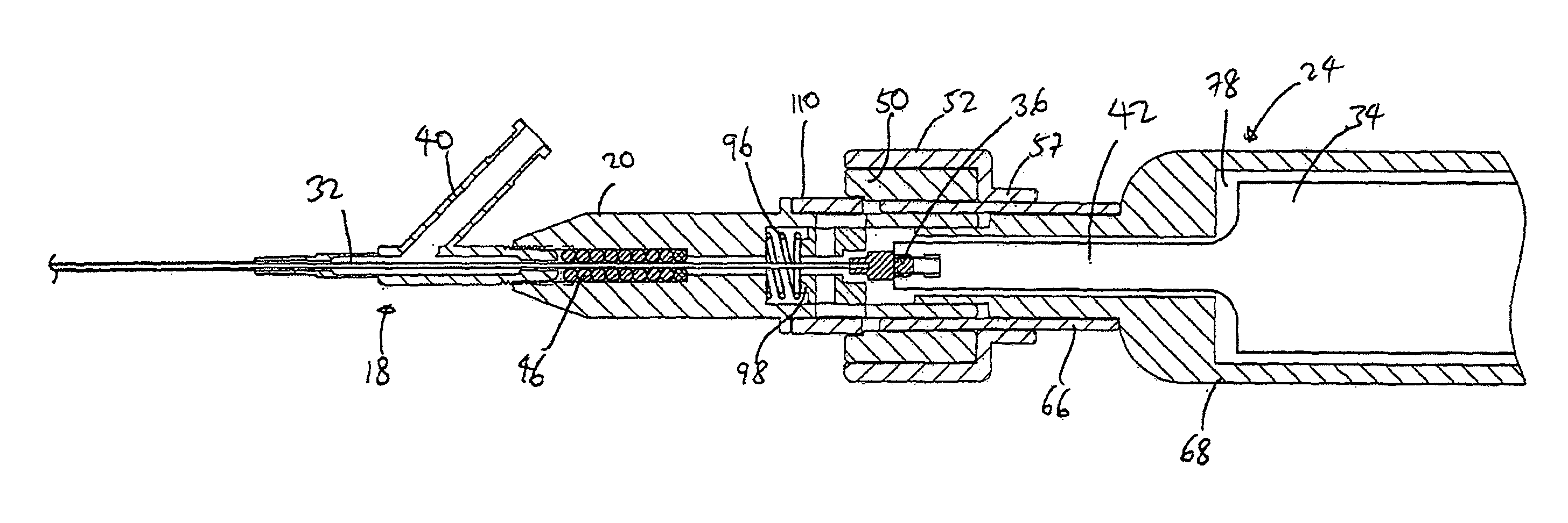
FIG. 2 is a cross-sectional view of the Y-connector and catheter knob of the system of FIG. 1.
FIG. 3 is a cross-sectional view of the Y-connector, the catheter knob, the slide collar assembly and the transducer housing of the system of FIG. 1 with the slide collar assembly in the non-supporting position.
FIG. 4 is a cross-sectional view of the Y-connector, the catheter knob, the slide collar assembly and the transducer housing of the system of FIG. 1 with the slide collar assembly in the supporting position.
FIG. 5 is an exploded perspective view of some of the elements of the slide collar assembly of the system of FIG. 1.
FIG. 6 is an assembled perspective view of the elements of FIG. 5.
FIG. 7 is an exploded perspective view of the catheter knob of the system of FIG. 1.
FIG. 8 is an assembled perspective view of the catheter knob of FIG. 7.
FIG. 9 is a perspective view of the system of FIG. 1 with the slide collar assembly in the non-supporting position.
FIG. 10 is a perspective view of the system of FIG. 1 with the slide collar assembly in the supporting position.
FIG. 11 is a perspective view of the catheter knob of the system of FIG. 1 with the slide collar assembly in the non-supporting position.
FIG. 12 is a perspective view of the catheter knob of the system of FIG. 1 with the slide collar assembly in the supporting position.
DETAILED DESCRIPTION OF THE PREFERRED EMBODIMENT
The following detailed description is of the best presently contemplated modes of carrying out the invention. This description is not to be taken in a limiting sense, but is made merely for the purpose of illustrating general principles of embodiments of the invention. The scope of the invention is best defined by the appended claims. In certain instances, detailed descriptions of well-known devices, compositions, components, mechanisms and methods are omitted so as to not obscure the description of the present invention with unnecessary detail.
FIG. 1 illustrates an ultrasound system according to the present invention for use in ablating and removing occlusive material inside the vessel of an animal or human being. The ultrasound system includes an ultrasonic catheter device 10 which has an elongate catheter body 12 having a proximal end 14, a distal end 16, and defining at least one lumen extending longitudinally therethrough. The ultrasound catheter device 10 is operatively coupled at its proximal end 14, by way of a Y-connector 18, a catheter knob 20, and a slide collar assembly 22, to an ultrasound transducer housing 24 As shown in FIGS. 3-4, an ultrasound transducer 34 is housed inside the transducer housing 24. The ultrasound transducer 34 is connected to a signal generator 26, which can be provided with a foot actuated on-off switch 28. The signal generator 26 can be supported by an IV pole 27. When the on-off switch 28 is depressed, the signal generator 26 sends an electrical signal to the ultrasound transducer 34, which converts the electrical signal to ultrasound energy. Such ultrasound energy subsequently passes through the catheter device 10 and is delivered to the distal end 16.
Referring also to FIGS. 2-4, an ultrasound transmission member 32 extends through the lumen of the catheter 10 from the distal end 16 to the proximal end 14. The ultrasound transducer 34 is coupled via a sonic connector 36 (described in greater detail below) to the ultrasound transmission member 32, so that the ultrasound energy can be passed through the sonic connector 36 and the ultrasound transmission member 32 to be delivered to the distal end 16 of the catheter 10. A guidewire 30, which can be any conventional monorail or over-the-wire guidewire, may be utilized in conjunction with the catheter 10 in a manner that is well-known in the catheter art.
The frontal portion of the Y-connector 18 is connected to the proximal end 12 of the catheter 10 using techniques that are well-known in the catheter art. An injection pump (not shown) or IV bag (not shown) can be connected, by way of an infusion tube (not shown), to an infusion port or sidearm 40 of the Y-connector 18. The injection pump can be used to infuse coolant fluid (e.g., 0.9% NaCl solution) into and/or through the lumen of the catheter 10. Such flow of coolant fluid may be utilized to prevent overheating of the ultrasound transmission member 32 extending longitudinally through the lumen of the catheter 10. Such flow of the coolant fluid through the lumen of the catheter 10 serves to bathe the outer surface of the ultrasound transmission member 32, thereby providing for an equilibration of temperature between the coolant fluid and the ultrasound transmission member 32. Thus, the temperature and/or flow rate of coolant fluid may be adjusted to provide adequate cooling and/or other temperature control of the ultrasound transmission member 32. In addition to the foregoing, the injection pump may be utilized to infuse a radiographic contrast medium into the catheter 10 for purposes of imaging.
Examples of iodinated radiographic contrast media which may be selectively infused into the catheter 10 via the injection pump are commercially available as Angiovist 370 from Berlex Labs, Wayne, N.J. and Hexabrix from Malinkrodt, St. Louis, Mo.
The proximal end of the ultrasound transmission member 32 is attached to the sonic connector 36 which is configured to effect operative and removable attachment of the proximal end of the ultrasound transmission member 32 to the distal horn 42 of the ultrasound transducer 34. The sonic connector 36 is preferably configured and constructed to permit passage of ultrasound energy through the ultrasound transmission member 32 with minimal lateral side-to-side movement of the ultrasound transmission member 32 while, at the same time, permitting unrestricted longitudinal forward/backward vibration or movement of the ultrasound transmission member 32.
The ultrasound transmission member 32 may be formed of any material capable of effectively transmitting the ultrasonic energy from the ultrasound transducer 34 to the distal end 16 of the catheter 10, including but not necessarily limited to metal, plastic, hard rubber, ceramic, fiber optics, crystal, polymers, and/or composites thereof. In accordance with one aspect of the invention, all or a portion of the ultrasound transmission member 32 may be formed of one or more materials which exhibit super-elasticity. Such materials should preferably exhibit super-elasticity consistently within the range of temperatures normally encountered by the ultrasound transmission member 32 during operation of the catheter 10. Specifically, all or part of the ultrasound transmission member 32 may be formed of one or more metal alloys known as "shape memory alloys". Such super-elastic metal alloys are well-known in the art and will not be described in any further detail herein.
The proximal end of the Y-connector 18 is attached to the distal end of the catheter knob 20 by threadably engaging the proximal end of the Y-connector 18 inside a threaded distal bore 44 at the distal end of the catheter knob 20. O-rings 46 are provided in the threaded distal bore 44 to minimize transverse vibrations. The proximal end of the catheter knob 20 receives the extension 70 of the transducer housing 24 and is supported by the slide collar assembly 22. The slide collar assembly 22 is positioned over the distal end of the transducer housing 24, and has a non-supporting position where the slide collar assembly 22 is retracted towards the transducer housing 24; and has a supporting position where the slide collar assembly 22 is extended to cover at least a portion of the catheter knob 20. Thus, the slide collar assembly 22 functions as a support member that is disposed on the transducer housing 24 to support at least a portion of the catheter knob 20.
Referring also to FIGS. 5 and 6, the slide collar assembly 22 has an inner ring 50 (also referred to as collar 50) and an outer ring 52 (also referred to as collar 52). The inner ring 50 has a bore 54 and a longitudinal slit 58 that extends through the length of the inner ring 50. The distal portion of the bore 54 can be stepped as shown at 55 (see FIG. 3) to function as a pushing surface that pushes a nesting piece 94 (described below) in a distal direction as the inner ring 50 is moved from the non-supporting position to the supporting position. The outer ring 52 also has a bore 56, and has a narrowed proximal end 57. The inner ring 50 is retained inside the bore 56 of the outer ring 52 and abuts the narrowed proximal end 57 which acts as a stop to limit the proximal movement of the inner ring 50. Each of the inner ring 50 and the outer ring 52 has an opening 60 and 62, respectively, that are aligned with each other and that are adapted to receive a locking pin 64. A tubular inner sleeve 66 extends through the inside of the bore 54 of the inner ring 50 to ensleeve the first extension 70 of the transducer housing 24, as explained below. The sleeve 66 has a proximal section 80 and an enlarged distal section 82. The inner ring 50 is normally fitted around the proximal section 80 when the slide collar assembly 22 is in the non-supporting position, but the inner ring 50 is fitted around the distal section 82 when the slide collar assembly 22 is in the supporting position. Thus, providing the distal section 82 in an enlarged configuration allows for the inner ring 50 to achieve a friction-fit with the distal section 82, while the inner ring 50 experiences a loose fit over the proximal section 80.
The transducer housing 24 has a cylindrical wall 68 having a distal extension that comprises two stepped cylindrical extensions 70 and 72 extending from the distal end of the cylindrical wall 68. The first extension 70 is attached to the distal end of the cylindrical wall 68, and has a greater outer diameter than the second extension 72 that is attached to the distal end of the first extension 70. A throughbore 76 extends from the hollow interior 78 of the cylindrical wall 68 and through the extensions 70 and 72. The throughbore 76 can have the same diameter throughout its length. The second extension 72 is adapted to be received inside the proximal bore 90 of the catheter knob 20, while the first extension 70 is received inside the sleeve 66. In addition, an opening 84 is provided in the proximal section 80 of the sleeve 66 and is aligned with a corresponding opening 86 on the first extension 70, with the openings 84, 86 adapted to receive a locking pin 88 that secures the sleeve 66 to the first extension 70 at a fixed position.
A longitudinal slot 92 is provided on the sleeve 66. When the slide collar assembly 22 is in the non-supporting position (i.e., inner ring 50 positioned over the proximal section 80), the slot 92 is opened. However, when the slide collar assembly 22 is moved to the supporting position, the inner ring 50 is positioned over the distal section 82 and compresses the enlarged distal section 82 to close the slot 92. With the slot 92 closed, the sleeve 66 provides a frictional grip of the proximal end 91 of the catheter knob 20.
Referring now to FIGS. 2-4 and 7-8, the catheter knob 20 has a proximal bore 90 that can be sleeved over the second extension 72 in a manner such that the outer surface of the catheter knob 20 can be substantially flush with the outer surface of the first extension 70 (as best shown in FIGS. 3 and 4). The proximal bore 90 houses the sonic connector 36 and a nesting piece 94. An elastic element 96, such as a spring, is seated in the distal part of the proximal bore 90, and has one end carried on a projection 98 provided at the distal end of the nesting piece 94. The nesting piece 94 has a generally cylindrical configuration and has a receptacle 100 which functions to selectively retain the sonic connector 36, as will be explained in greater detail below. In addition, a control ring 110 is positioned around the outer surface 112 of the catheter knob 20. The control ring 112 cooperates with the nesting piece 94 to move the nesting piece 94 in a reciprocal manner inside the proximal bore 90 of the catheter knob 20, as explained below.
The nesting piece 94 has two opposite and aligned openings 102; only the top opening 102 is shown in FIG. 7, but the bottom opening is the same and is aligned on a straight line with the top opening 102. Similarly, the catheter knob 20 has two opposite and aligned channels 104; only the top channel 104 is shown in FIG. 7, but the bottom channel is the same and is aligned on a straight line with the top channel 104. In addition, the control ring 110 has two opposite and aligned openings 114. The channels 104 and the openings 102, 114 are aligned, as best shown in FIGS. 3 and 4. Two opposing pins 106 are provided, with each pin 106 adapted to be fitted inside a corresponding set of channel 104 and openings 102, 114, so as to couple the control ring 110 and the nesting piece 94 as a unitary moving piece. The width of the channels 104 define the distal and proximal limits of movement for the control ring 110 and the nesting piece 94. The catheter knob 20 also has an annular flange 116 provided about its outer surface 112 that also defines the distal limit of the movement of the control ring 110.
In use, the sonic connector 36 is shown in FIGS. 3-4 as connecting the transducer horn 42 (e.g., with a threaded connection) with the ultrasound transmission member 32. The sonic connector 36 is always located at a fixed position inside the proximal bore 90 of the catheter knob 20. When the slide collar assembly 22 is in the non-supporting position shown in FIGS. 3, 9 and 11, the elastic element 96 normally biases the nesting piece 94 in the proximal direction so that the sonic connector 36 is received inside the receptacle 100 of the nesting piece 94 to be supported by the nesting piece 94. The proximal movement of the nesting piece 94 will cause the pins 106 to move in the proximal direction inside the channels 104, thereby causing the control ring 110 to move proximally away from the flange 116. The outer ring 52 and the inner ring 50 are positioned completely over the proximal section 80 of the sleeve 66, with the narrowed proximal end 57 positioned adjacent the cylindrical wall 68 of the transducer housing 24.
When the slide collar assembly 22 is now moved from the non-supporting position to the supporting position shown in FIGS. 4, 10 and 12, the user pushes the outer ring 52 in the distal direction. The step 55 on the distal end of the inner ring 50 engages the proximal end of the control ring 110 and pushes the control ring 110 in the distal direction, Movement of the control ring 110 in the distal direction will cause the pins 106 to move in the distal direction inside the channels 104, thereby causing the nesting piece 94 to counter the bias of the elastic element 96 and move in the distal direction. As the nesting piece 94 moves in the distal direction, the sonic connector 36 becomes free from the receptacle 100 of the nesting bore 94. In addition, the distal movement of the inner ring 50 will cause the inner surface of the inner ring 50 to engage the enlarged distal section 82 of the sleeve 66, which functions to close the slot 92 so as to frictionally grip the proximal portion 91 of the knob 20 when the slide collar assembly 22 is in the supporting position. The flange 116 and the width of the channels 104 function as stops to limit the distal movement of the control ring 110.
In the supporting position, the sonic connector 36 is not supported by the nesting piece 94 so that the sonic connector 36 can be free from any component or material interfaces, thereby promoting improved ultrasound energy propagation. The medical procedure can then be earned out while the slide collar assembly 22 is in the supporting position. Upon completion of the medical procedure, the above-described steps are reversed. In particular, the combined inner and outer rings 50, 52 (slide collar assembly 22) are retracted in the proximal direction so that they are now positioned over the proximal section 80 of the sleeve 66. The bias of the elastic element 96 will push the nesting piece 94 in the proximal direction so that the sonic connector 36 is received inside the receptacle 100 of the nesting piece 94. In addition, the proximal movement of the nesting piece 94 will cause the pins 106 to move in the proximal direction inside the channels 104, thereby causing the control ring 110 to move proximally away from the flange 116. Now, the catheter 10 can be disconnected from the transducer 34.
While the description above refers to particular embodiments of the present invention, it will be understood that many modifications may be made without departing from the spirit thereof. The accompanying claims are intended to cover such modifications as would fall within the true scope and spirit of the present invention.
* * * * *
References
D00000
D00001
D00002
D00003
D00004
D00005
D00006
D00007
XML
uspto.report is an independent third-party trademark research tool that is not affiliated, endorsed, or sponsored by the United States Patent and Trademark Office (USPTO) or any other governmental organization. The information provided by uspto.report is based on publicly available data at the time of writing and is intended for informational purposes only.
While we strive to provide accurate and up-to-date information, we do not guarantee the accuracy, completeness, reliability, or suitability of the information displayed on this site. The use of this site is at your own risk. Any reliance you place on such information is therefore strictly at your own risk.
All official trademark data, including owner information, should be verified by visiting the official USPTO website at www.uspto.gov. This site is not intended to replace professional legal advice and should not be used as a substitute for consulting with a legal professional who is knowledgeable about trademark law.