Devices and methods for endovascular electrography
Grunwald July 16, 2
U.S. patent number 10,349,857 [Application Number 15/266,977] was granted by the patent office on 2019-07-16 for devices and methods for endovascular electrography. This patent grant is currently assigned to Bard Access Systems, Inc.. The grantee listed for this patent is Bard Access Systems, Inc.. Invention is credited to Sorin Grunwald.


View All Diagrams
| United States Patent | 10,349,857 |
| Grunwald | July 16, 2019 |
Devices and methods for endovascular electrography
Abstract
A method for positioning an endovascular device in or near the heart using electrocardiogram (ECG) signals. The method includes receiving an endovascular ECG signal including a plurality of waveforms, processing the endovascular ECG signal to calculate a P-wave amplitude and a spectral power for each predetermined time period, determining a maximum P-wave amplitude and an associated maximum spectral power, associating the maximum P-wave amplitude and the maximum spectral power with a predetermined location in or near the heart, calculating a location based on a ratio of the P-wave amplitude to the maximum P-wave amplitude and a ratio of the spectral power to the maximum spectral power, and displaying the location to a user.
| Inventors: | Grunwald; Sorin (Bucharest, RO) | ||||||||||
|---|---|---|---|---|---|---|---|---|---|---|---|
| Applicant: |
|
||||||||||
| Assignee: | Bard Access Systems, Inc. (Salt
Lake City, UT) |
||||||||||
| Family ID: | 43586787 | ||||||||||
| Appl. No.: | 15/266,977 | ||||||||||
| Filed: | September 15, 2016 |
Prior Publication Data
| Document Identifier | Publication Date | |
|---|---|---|
| US 20170000367 A1 | Jan 5, 2017 | |
Related U.S. Patent Documents
| Application Number | Filing Date | Patent Number | Issue Date | ||
|---|---|---|---|---|---|
| 12854083 | Sep 20, 2016 | 9445734 | |||
| 12815331 | May 17, 2016 | 9339206 | |||
| 61213474 | Jun 12, 2009 | ||||
| 61272025 | Aug 10, 2009 | ||||
| Current U.S. Class: | 1/1 |
| Current CPC Class: | A61B 5/04017 (20130101); A61M 25/0147 (20130101); A61B 5/042 (20130101); A61B 5/0452 (20130101); A61M 25/0026 (20130101); A61B 5/06 (20130101); A61B 5/065 (20130101); A61B 34/20 (20160201); A61N 1/056 (20130101); A61B 5/742 (20130101); A61M 25/0097 (20130101); A61M 25/0102 (20130101); A61M 25/0194 (20130101); A61B 5/726 (20130101); A61B 5/7203 (20130101); A61M 2025/09116 (20130101); A61M 2039/1022 (20130101) |
| Current International Class: | A61N 1/05 (20060101); A61B 5/0452 (20060101); A61B 5/04 (20060101); A61B 34/20 (20160101); A61B 5/00 (20060101); A61B 5/042 (20060101); A61B 5/06 (20060101); A61M 25/00 (20060101); A61M 25/01 (20060101); A61M 25/09 (20060101); A61M 39/10 (20060101) |
References Cited [Referenced By]
U.S. Patent Documents
| 3795855 | March 1974 | Browning |
| 3817241 | June 1974 | Grausz |
| 3902501 | September 1975 | Citron et al. |
| 3995623 | December 1976 | Blake et al. |
| 4365639 | December 1982 | Goldreyer |
| 4565201 | January 1986 | Lass |
| 4577634 | March 1986 | Gessman |
| 4587975 | May 1986 | Salo et al. |
| 4595012 | June 1986 | Webler et al. |
| 4644960 | February 1987 | Johans |
| 4681117 | July 1987 | Brodman et al. |
| 4793361 | December 1988 | DuFault |
| 4809681 | March 1989 | Kantrowitz et al. |
| 4821731 | April 1989 | Martinelli et al. |
| 4836214 | June 1989 | Sramek |
| 4852580 | August 1989 | Wood |
| 4873987 | October 1989 | Djordjevich et al. |
| 4905698 | March 1990 | Strohl, Jr. et al. |
| 4957110 | September 1990 | Vogel et al. |
| 5029585 | July 1991 | Lieber et al. |
| 5058583 | October 1991 | Geddes et al. |
| 5058595 | October 1991 | Kern |
| 5092341 | March 1992 | Kelen |
| 5109862 | May 1992 | Kelen et al. |
| 5121750 | June 1992 | Katims |
| 5146151 | September 1992 | Korn |
| 5184627 | February 1993 | de Toledo |
| 5220924 | June 1993 | Frazin |
| 5243995 | September 1993 | Maier |
| 5269306 | December 1993 | Warnking et al. |
| 5330496 | July 1994 | Alferness |
| 5385146 | January 1995 | Goldreyer |
| 5398683 | March 1995 | Edwards et al. |
| 5417701 | May 1995 | Holmes |
| 5450846 | September 1995 | Goldreyer |
| 5500011 | March 1996 | Desai |
| 5517989 | May 1996 | Frisbie et al. |
| 5540681 | July 1996 | Strul et al. |
| 5570671 | November 1996 | Hickey |
| 5640967 | June 1997 | Fine et al. |
| 5718241 | February 1998 | Ben-Haim et al. |
| 5727550 | March 1998 | Montecalvo |
| 5730129 | March 1998 | Darrow et al. |
| 5769786 | June 1998 | Wiegel |
| 5820560 | October 1998 | Sinderby et al. |
| 5830145 | November 1998 | Tenhoff |
| 5833622 | November 1998 | Meathrel et al. |
| 5840030 | November 1998 | Ferek-Petric et al. |
| 5840031 | November 1998 | Crowley |
| 5846198 | December 1998 | Killmann |
| 5899860 | May 1999 | Pfeiffer et al. |
| 5908385 | June 1999 | Chechelski et al. |
| 5931863 | August 1999 | Griffin, III et al. |
| 5935160 | August 1999 | Auricchio et al. |
| 5944022 | August 1999 | Nardella et al. |
| 5951472 | September 1999 | Van Vaals et al. |
| 5967978 | October 1999 | Littmann et al. |
| 5983126 | November 1999 | Wittkampf |
| 6006123 | December 1999 | Nguyen et al. |
| 6014473 | January 2000 | Hossack et al. |
| 6019725 | February 2000 | Vesely et al. |
| 6052618 | April 2000 | Dahlke et al. |
| 6058323 | May 2000 | Lemelson |
| 6063032 | May 2000 | Grunwald |
| 6102862 | August 2000 | Grunwald et al. |
| 6107699 | August 2000 | Swanson |
| 6115624 | September 2000 | Lewis et al. |
| 6190370 | February 2001 | Tsui |
| 6197001 | March 2001 | Wilson et al. |
| 6212426 | April 2001 | Swanson |
| 6217517 | April 2001 | Grunwald |
| 6230042 | May 2001 | Slettenmark |
| 6231518 | May 2001 | Grabek et al. |
| 6236883 | May 2001 | Ciaccio et al. |
| 6246898 | June 2001 | Vesely et al. |
| 6249234 | June 2001 | Ely et al. |
| 6254543 | July 2001 | Grunwald et al. |
| 6259938 | July 2001 | Zarychta et al. |
| 6266551 | July 2001 | Osadchy et al. |
| 6266552 | July 2001 | Slettenmark |
| 6266563 | July 2001 | KenKnight et al. |
| 6275724 | August 2001 | Dickinson et al. |
| 6287259 | September 2001 | Grunwald |
| 6324416 | November 2001 | Seibert |
| 6350160 | February 2002 | Feuersanger et al. |
| 6354999 | March 2002 | Dgany et al. |
| 6360123 | March 2002 | Kimchi et al. |
| 6379303 | April 2002 | Seitz et al. |
| 6385476 | May 2002 | Osadchy et al. |
| 6398738 | June 2002 | Millar |
| 6406422 | June 2002 | Landesberg |
| 6471656 | October 2002 | Shalman et al. |
| 6494832 | December 2002 | Feldman et al. |
| 6508802 | January 2003 | Rosengart et al. |
| 6511413 | January 2003 | Landesberg |
| 6514202 | February 2003 | Grunwald |
| 6514249 | February 2003 | Maguire et al. |
| 6522906 | February 2003 | Salisbury, Jr. et al. |
| 6538634 | March 2003 | Chui et al. |
| 6540699 | April 2003 | Smith et al. |
| 6546270 | April 2003 | Goldin et al. |
| 6569160 | May 2003 | Goldin et al. |
| 6569862 | May 2003 | Marban |
| 6577896 | June 2003 | Werner et al. |
| 6584343 | June 2003 | Ransbury et al. |
| 6589181 | July 2003 | Grunwald et al. |
| 6649914 | November 2003 | Moorman et al. |
| 6690968 | February 2004 | Mejia |
| 6709390 | March 2004 | Marie Pop |
| 6719756 | April 2004 | Muntermann |
| 6733458 | May 2004 | Steins et al. |
| 6763261 | July 2004 | Casscells, III et al. |
| 6816266 | November 2004 | Varshneya et al. |
| 6941166 | September 2005 | MacAdam et al. |
| 6945938 | September 2005 | Grunwald |
| 6950689 | September 2005 | Willis et al. |
| 6959214 | October 2005 | Pape et al. |
| 7015393 | March 2006 | Weiner et al. |
| 7096059 | August 2006 | Geddes et al. |
| 7141019 | November 2006 | Pearlman |
| 7184820 | February 2007 | Jersey-Willuhn et al. |
| 7190819 | March 2007 | Viswanathan |
| 7207941 | April 2007 | Sharf |
| 7231243 | June 2007 | Tearney et al. |
| 7261691 | August 2007 | Asomani |
| 7299085 | November 2007 | Bergelson et al. |
| 7308296 | December 2007 | Lys et al. |
| 7327872 | February 2008 | Vaillant et al. |
| 7331462 | February 2008 | Steppe |
| 7366563 | April 2008 | Kleen et al. |
| 7479141 | January 2009 | Kleen et al. |
| 7529584 | May 2009 | Laske et al. |
| 7546158 | June 2009 | Allison et al. |
| 7613478 | November 2009 | Jabri et al. |
| 7640053 | December 2009 | Verin |
| 7666191 | February 2010 | Orban, III et al. |
| 7699829 | April 2010 | Harris et al. |
| 7729743 | June 2010 | Sabczynski et al. |
| 7774051 | August 2010 | Voth |
| 7774055 | August 2010 | Min |
| 7822464 | October 2010 | Maschke et al. |
| 7831294 | November 2010 | Viswanathan |
| 7840252 | November 2010 | Strommer et al. |
| 7846157 | December 2010 | Kozel |
| 7869854 | January 2011 | Shachar et al. |
| 7869865 | January 2011 | Govari et al. |
| 7873402 | January 2011 | Shachar |
| 7947040 | May 2011 | Davies et al. |
| 7969142 | June 2011 | Krueger et al. |
| 8055327 | November 2011 | Strommer et al. |
| 8057394 | November 2011 | Dala-Krishna |
| 8082025 | December 2011 | Amitai et al. |
| 8090430 | January 2012 | Makower et al. |
| 8105338 | January 2012 | Anderson et al. |
| 8155732 | April 2012 | Scholz et al. |
| 8241274 | August 2012 | Keogh et al. |
| 8244339 | August 2012 | Shen et al. |
| 8255035 | August 2012 | Cao et al. |
| 8303505 | November 2012 | Webler et al. |
| 8326419 | December 2012 | Rosenberg et al. |
| 8326651 | December 2012 | McLaren et al. |
| 8346343 | January 2013 | Kimura et al. |
| 8369922 | February 2013 | Paul et al. |
| 8388541 | March 2013 | Messerly et al. |
| 8391956 | March 2013 | Zellers et al. |
| 8400164 | March 2013 | Osadchy et al. |
| 8401616 | March 2013 | Verard et al. |
| 8412313 | April 2013 | Amitai et al. |
| 8456182 | June 2013 | Bar-Tal et al. |
| 8478388 | July 2013 | Nguyen et al. |
| 8494608 | July 2013 | Markowitz et al. |
| 8504139 | August 2013 | Jacobsen et al. |
| 8521122 | August 2013 | Scott et al. |
| 8527036 | September 2013 | Jalde et al. |
| 8538509 | September 2013 | Harlev et al. |
| 8597193 | December 2013 | Grunwald et al. |
| 8620412 | December 2013 | Griffiths et al. |
| 8644907 | February 2014 | Hartmann et al. |
| 8663116 | March 2014 | Hamilton, Jr. |
| 8690776 | April 2014 | Razzaque et al. |
| 8700137 | April 2014 | Albert |
| 8715195 | May 2014 | Ziv |
| 8721655 | May 2014 | Viswanathan et al. |
| 8761862 | June 2014 | Ridley et al. |
| 8942784 | January 2015 | Neidert et al. |
| 8965490 | February 2015 | Lee et al. |
| 8971994 | March 2015 | Burnside et al. |
| 9014794 | April 2015 | Brodnick et al. |
| 9033889 | May 2015 | Hamilton, Jr. |
| 9179860 | November 2015 | Markowitz et al. |
| 9198600 | December 2015 | Grunwald et al. |
| 9415188 | August 2016 | He et al. |
| 9456766 | October 2016 | Cox et al. |
| 9492097 | November 2016 | Wilkes et al. |
| 9521961 | December 2016 | Silverstein et al. |
| 9526440 | December 2016 | Burnside et al. |
| 9532724 | January 2017 | Grunwald |
| 9554716 | January 2017 | Burnside et al. |
| 9636031 | May 2017 | Cox |
| 9642986 | May 2017 | Beasley |
| 9649048 | May 2017 | Cox et al. |
| 9681823 | June 2017 | Messerly et al. |
| 9833169 | December 2017 | Rothenberg |
| 9839372 | December 2017 | Bukhman et al. |
| 9901714 | February 2018 | Lemon et al. |
| 9907513 | March 2018 | Silverstein |
| 9999371 | June 2018 | Messerly et al. |
| 10004875 | June 2018 | Bown et al. |
| 10046139 | August 2018 | Powers et al. |
| 10105121 | October 2018 | Burnside et al. |
| 10165962 | January 2019 | Messerly et al. |
| 10231643 | March 2019 | Grunwald |
| 10231753 | March 2019 | Burnside et al. |
| 10238418 | March 2019 | Cox et al. |
| 10271762 | April 2019 | Grunwald |
| 2001/0014774 | August 2001 | Grunwald |
| 2001/0027332 | October 2001 | Grunwald et al. |
| 2002/0173721 | November 2002 | Grunwald et al. |
| 2002/0193756 | December 2002 | Prindle |
| 2003/0009132 | January 2003 | Schwartz et al. |
| 2003/0013959 | January 2003 | Grunwald et al. |
| 2003/0018251 | January 2003 | Solomon |
| 2003/0036696 | February 2003 | Willis et al. |
| 2003/0083698 | May 2003 | Whitehurst et al. |
| 2003/0092993 | May 2003 | Grunwald |
| 2003/0149368 | August 2003 | Hennemann et al. |
| 2003/0162414 | August 2003 | Schulz et al. |
| 2003/0220578 | November 2003 | Ho et al. |
| 2003/0236445 | December 2003 | Couvillon |
| 2004/0059217 | March 2004 | Kessman et al. |
| 2004/0059237 | March 2004 | Narayan et al. |
| 2004/0138569 | July 2004 | Grunwald et al. |
| 2004/0150963 | August 2004 | Holmberg et al. |
| 2004/0243118 | December 2004 | Ayers et al. |
| 2004/0267086 | December 2004 | Anstadt et al. |
| 2005/0085715 | April 2005 | Dukesherer et al. |
| 2005/0178396 | August 2005 | Hunter et al. |
| 2005/0182454 | August 2005 | Gharib et al. |
| 2005/0256398 | November 2005 | Hastings et al. |
| 2005/0283210 | December 2005 | Blischak et al. |
| 2005/0283216 | December 2005 | Pyles |
| 2006/0217755 | September 2006 | Eversull et al. |
| 2006/0241432 | October 2006 | Herline et al. |
| 2006/0253029 | November 2006 | Altmann et al. |
| 2006/0253115 | November 2006 | Avitall et al. |
| 2006/0287595 | December 2006 | Maschke |
| 2007/0010753 | January 2007 | MacAdam |
| 2007/0016007 | January 2007 | Govari et al. |
| 2007/0016013 | January 2007 | Camus |
| 2007/0049817 | March 2007 | Preiss et al. |
| 2007/0049846 | March 2007 | Bown et al. |
| 2007/0055141 | March 2007 | Kruger et al. |
| 2007/0055142 | March 2007 | Webler |
| 2007/0055294 | March 2007 | Giap |
| 2007/0060992 | March 2007 | Pappone |
| 2007/0066888 | March 2007 | Maschke |
| 2007/0078343 | April 2007 | Kawashima et al. |
| 2007/0093710 | April 2007 | Maschke |
| 2007/0135803 | June 2007 | Belson |
| 2007/0135886 | June 2007 | Maschke |
| 2007/0161914 | July 2007 | Zdeblick et al. |
| 2007/0161915 | July 2007 | Desai |
| 2007/0167738 | July 2007 | Timinger et al. |
| 2007/0197905 | August 2007 | Timinger et al. |
| 2007/0197926 | August 2007 | Danehorn et al. |
| 2007/0225589 | September 2007 | Viswanathan |
| 2007/0225610 | September 2007 | Mickley et al. |
| 2007/0232882 | October 2007 | Glossop et al. |
| 2007/0232896 | October 2007 | Gilboa et al. |
| 2007/0239004 | October 2007 | Kakee et al. |
| 2007/0247454 | October 2007 | Rahn et al. |
| 2007/0299353 | December 2007 | Harley et al. |
| 2008/0033282 | February 2008 | Bar-Tal et al. |
| 2008/0081958 | April 2008 | Denison et al. |
| 2008/0082136 | April 2008 | Gaudiani |
| 2008/0108949 | May 2008 | Beasley et al. |
| 2008/0119697 | May 2008 | Vadodaria et al. |
| 2008/0137927 | June 2008 | Altmann et al. |
| 2008/0146939 | June 2008 | McMorrow et al. |
| 2008/0146940 | June 2008 | Jenkins et al. |
| 2008/0146941 | June 2008 | Dala-Krishna |
| 2008/0146942 | June 2008 | Dala-Krishna |
| 2008/0190438 | August 2008 | Harlev et al. |
| 2008/0200801 | August 2008 | Wildes et al. |
| 2008/0200913 | August 2008 | Viswanathan |
| 2008/0269581 | October 2008 | Wood et al. |
| 2009/0062646 | March 2009 | Creighton, IV et al. |
| 2009/0062772 | March 2009 | Wakeford et al. |
| 2009/0080738 | March 2009 | Zur et al. |
| 2009/0099468 | April 2009 | Thiagalingam et al. |
| 2009/0115406 | May 2009 | Anderson et al. |
| 2009/0204113 | August 2009 | MacAdam et al. |
| 2009/0209872 | August 2009 | Pop |
| 2009/0209950 | August 2009 | Starksen |
| 2009/0270729 | October 2009 | Corbucci et al. |
| 2009/0270746 | October 2009 | Min |
| 2009/0281419 | November 2009 | Troesken et al. |
| 2009/0312629 | December 2009 | Razzaque et al. |
| 2010/0004547 | January 2010 | Scholz et al. |
| 2010/0041973 | February 2010 | Vu et al. |
| 2010/0049062 | February 2010 | Ziv |
| 2010/0076328 | March 2010 | Matsumura et al. |
| 2010/0106011 | April 2010 | Byrd et al. |
| 2010/0113917 | May 2010 | Anderson |
| 2010/0117659 | May 2010 | Osadchy et al. |
| 2010/0130858 | May 2010 | Arai et al. |
| 2010/0152596 | June 2010 | Griffiths et al. |
| 2010/0152604 | June 2010 | Kaula et al. |
| 2010/0160772 | June 2010 | Gardeski et al. |
| 2010/0204614 | August 2010 | Lindquist et al. |
| 2010/0217116 | August 2010 | Eck et al. |
| 2010/0274150 | October 2010 | Harley et al. |
| 2010/0291521 | November 2010 | Simon |
| 2011/0015496 | January 2011 | Sherman et al. |
| 2011/0106101 | May 2011 | Tortonese et al. |
| 2011/0282187 | November 2011 | Harlev et al. |
| 2011/0282285 | November 2011 | Blanchard et al. |
| 2011/0282686 | November 2011 | Venon et al. |
| 2011/0295108 | December 2011 | Cox et al. |
| 2011/0306859 | December 2011 | Saldivar et al. |
| 2012/0004564 | January 2012 | Dobak, III |
| 2012/0059270 | March 2012 | Grunwald |
| 2012/0059271 | March 2012 | Amitai et al. |
| 2012/0071751 | March 2012 | Sra et al. |
| 2012/0071782 | March 2012 | Patil et al. |
| 2012/0095319 | April 2012 | Kondrosky et al. |
| 2012/0143029 | June 2012 | Silverstein et al. |
| 2012/0265084 | October 2012 | Stewart et al. |
| 2012/0296200 | November 2012 | Shachar et al. |
| 2012/0310052 | December 2012 | Mahapatra et al. |
| 2012/0310066 | December 2012 | Shachar et al. |
| 2012/0310660 | December 2012 | Liu et al. |
| 2013/0006100 | January 2013 | Shachar et al. |
| 2013/0018248 | January 2013 | Hurezan |
| 2013/0041254 | February 2013 | Hagy et al. |
| 2013/0079628 | March 2013 | Groszmann et al. |
| 2013/0085416 | April 2013 | Mest |
| 2013/0090938 | April 2013 | Fishman et al. |
| 2013/0131503 | May 2013 | Schneider et al. |
| 2013/0169272 | July 2013 | Eichler et al. |
| 2013/0281837 | October 2013 | Ridley et al. |
| 2013/0289417 | October 2013 | Grunwald et al. |
| 2013/0296693 | November 2013 | Wenzel et al. |
| 2013/0303878 | November 2013 | Nevo et al. |
| 2013/0303945 | November 2013 | Blumenkranz et al. |
| 2013/0345555 | December 2013 | Kanade et al. |
| 2014/0089836 | March 2014 | Damani et al. |
| 2014/0128712 | May 2014 | Banet et al. |
| 2014/0187917 | July 2014 | Clark et al. |
| 2014/0187990 | July 2014 | Banet et al. |
| 2014/0221862 | August 2014 | Tambe |
| 2014/0249428 | September 2014 | Ingold, Jr. et al. |
| 2014/0249505 | September 2014 | Bukhman |
| 2014/0253270 | September 2014 | Nicholls et al. |
| 2014/0257080 | September 2014 | Dunbar et al. |
| 2014/0276010 | September 2014 | Anderson |
| 2015/0025365 | January 2015 | Esguerra Wilczynski et al. |
| 2015/0025402 | January 2015 | Rothenberg |
| 2015/0073285 | March 2015 | Albert et al. |
| 2015/0080716 | March 2015 | Powers et al. |
| 2015/0209008 | July 2015 | Ridley et al. |
| 2015/0216445 | August 2015 | Carmeli et al. |
| 2015/0216446 | August 2015 | Bukhman et al. |
| 2015/0223775 | August 2015 | Hamilton, Jr. |
| 2015/0245809 | September 2015 | Hagy et al. |
| 2015/0245872 | September 2015 | Hagy et al. |
| 2015/0246247 | September 2015 | Binnekamp et al. |
| 2015/0282734 | October 2015 | Schweikert et al. |
| 2015/0289781 | October 2015 | Grunwald et al. |
| 2015/0317810 | November 2015 | Grunwald et al. |
| 2015/0335310 | November 2015 | Bernstein et al. |
| 2015/0335383 | November 2015 | Cohen |
| 2016/0067449 | March 2016 | Misener et al. |
| 2016/0278869 | September 2016 | Grunwald |
| 2016/0374589 | December 2016 | Misener et al. |
| 2017/0020561 | January 2017 | Cox et al. |
| 2017/0079548 | March 2017 | Silverstein et al. |
| 2017/0079552 | March 2017 | Grunwald |
| 2017/0079615 | March 2017 | Burnside et al. |
| 2017/0079681 | March 2017 | Burnside et al. |
| 2017/0086782 | March 2017 | Hagy et al. |
| 2017/0151022 | June 2017 | Jascob et al. |
| 2017/0215762 | August 2017 | Burnside et al. |
| 2017/0231700 | August 2017 | Cox et al. |
| 2017/0281029 | October 2017 | Messerly et al. |
| 2018/0070856 | March 2018 | Grunwald |
| 2018/0103869 | April 2018 | Bukhman et al. |
| 2018/0116551 | May 2018 | Newman et al. |
| 2018/0169389 | June 2018 | Lemon et al. |
| 2019/0069877 | March 2019 | Burnside et al. |
| 2019/0099108 | April 2019 | Messerly et al. |
| 2031655 | Feb 1989 | CN | |||
| 1913833 | Feb 2007 | CN | |||
| 101854853 | Oct 2010 | CN | |||
| 1319033 | Jun 1994 | DE | |||
| 0359697 | Mar 1990 | EP | |||
| 0362821 | Apr 1990 | EP | |||
| 1015967 | Apr 2002 | EP | |||
| 1504713 | Feb 2005 | EP | |||
| 1117331 | May 2005 | EP | |||
| 1117332 | Aug 2005 | EP | |||
| 1118019 | May 2006 | EP | |||
| 1717601 | Nov 2006 | EP | |||
| 1887940 | Feb 2008 | EP | |||
| 2531098 | Dec 2012 | EP | |||
| 2605699 | Jun 2013 | EP | |||
| 2474268 | Jul 2013 | EP | |||
| 2618727 | Jul 2013 | EP | |||
| 2992825 | May 2017 | EP | |||
| 2170162 | Aug 2017 | EP | |||
| 2265175 | Aug 2017 | EP | |||
| 2001-145630 | May 2001 | JP | |||
| 2002-224069 | Aug 2002 | JP | |||
| 2007-105450 | Apr 2007 | JP | |||
| 2007-313122 | Dec 2007 | JP | |||
| 2009101949 | Jul 2010 | RU | |||
| 1980002376 | Nov 1980 | WO | |||
| 1997/22395 | Jun 1997 | WO | |||
| 97/48438 | Dec 1997 | WO | |||
| 1998035611 | Aug 1998 | WO | |||
| 1999049407 | Sep 1999 | WO | |||
| 2000074775 | Dec 2000 | WO | |||
| 2001013792 | Mar 2001 | WO | |||
| 02/07794 | Jan 2002 | WO | |||
| 2003077759 | Sep 2003 | WO | |||
| 2004002303 | Jan 2004 | WO | |||
| 2005/089851 | Sep 2005 | WO | |||
| 2005117690 | Dec 2005 | WO | |||
| 2005117733 | Dec 2005 | WO | |||
| 2007002541 | Jan 2007 | WO | |||
| 2007005976 | Jan 2007 | WO | |||
| 2007067324 | Jun 2007 | WO | |||
| 2007069168 | Jun 2007 | WO | |||
| 2007109123 | Sep 2007 | WO | |||
| 2007126536 | Nov 2007 | WO | |||
| 2008097767 | Aug 2008 | WO | |||
| 2008118992 | Oct 2008 | WO | |||
| 2008126074 | Oct 2008 | WO | |||
| 2008129326 | Oct 2008 | WO | |||
| 2008131017 | Oct 2008 | WO | |||
| 2008136008 | Nov 2008 | WO | |||
| 2009003138 | Dec 2008 | WO | |||
| 2009100158 | Aug 2009 | WO | |||
| 2009123819 | Oct 2009 | WO | |||
| 2009126340 | Oct 2009 | WO | |||
| 2009129477 | Oct 2009 | WO | |||
| 2009134605 | Nov 2009 | WO | |||
| 2010018500 | Feb 2010 | WO | |||
| 2011057289 | May 2011 | WO | |||
| 2012039866 | Mar 2012 | WO | |||
| 2012173697 | Dec 2012 | WO | |||
| 2014042329 | Mar 2014 | WO | |||
| 2015/055797 | Apr 2015 | WO | |||
| 2015048514 | Apr 2015 | WO | |||
| 2015073962 | May 2015 | WO | |||
| 2015/120256 | Aug 2015 | WO | |||
| 2016/210325 | Dec 2016 | WO | |||
| 2018/112252 | Jun 2018 | WO | |||
Other References
|
AU 2012278809 filed Nov. 12, 2013 Notice of Acceptance dated Sep. 13, 2016. cited by applicant . CA 2,721,715 filed Apr. 17, 2009 Examiner's Report dated Oct. 25, 2016. cited by applicant . CA 2800810 filed Nov. 26, 2012 Office Action dated Mar. 30, 2017. cited by applicant . CN 200980144663.8 filed May 9, 2011 Decision of Re-Examination dated Feb. 21, 2017. cited by applicant . CN 200980144663.8 filed May 9, 2011 Notice of Reexamination dated Aug. 5, 2016. cited by applicant . CN 201180037065.8 filed Jan. 28, 2013 Notice of Grant dated Aug. 30, 2016. cited by applicant . CN 201380051172.5 filed Mar. 30, 2015 Office Action dated May 2, 2017. cited by applicant . CN 201380065663.5 filed Jun. 15, 2015 Office Action dated Mar. 15, 2017. cited by applicant . CN 201510144728.6 filed Apr. 17, 2015 Office Action dated Jan. 23, 2017. cited by applicant . CO 15110530 filed May 14, 2015 Office Action dated May 8, 2017. cited by applicant . CO 15110530 filed May 14, 2015 Office Action dated Nov. 25, 2016. cited by applicant . EP 09743249.6 filed Oct. 18, 2010 Intention to Grant dated Mar. 2, 2017. cited by applicant . EP 11850625.2 filed Jul. 22, 2013 Extended European Search Report dated Jun. 21, 2017. cited by applicant . EP 13840356.3 filed Apr. 27, 2015 Extended European Search Report dated Mar. 22, 2017. cited by applicant . EP 13840356.3 filed Apr. 27, 2015 Partial European Search Report dated Oct. 19, 2016. cited by applicant . EP 13846380.7 filed May 15, 2015 Extended European Search Report dated Sep. 30, 2016. cited by applicant . EP 13846380.7 filed May 15, 2015 Partial European Search Report dated Sep. 30, 2016. cited by applicant . EP 14761249.3 Filed Sep. 3, 2015 Extended European Search Report dated Sep. 19, 2016. cited by applicant . EP 15746326.6 filed Jul. 1, 2016 Extended European Search Report dated Jun. 9, 2017. cited by applicant . EP 17157118.5 filed Feb. 21, 2017 Extended European Search Report Jun. 8, 2017. cited by applicant . JP 2013-530322 filed Mar. 18, 2013, Office Action dated Mar. 2, 2017. cited by applicant . JP 2015-534770 filed Mar. 26, 2015 Office Action dated Jun. 12, 2017. cited by applicant . KR 10-2012-7000866 filed Jan. 11, 2012 Second Office Action dated Nov. 3, 2016. cited by applicant . PCT/US2016/039356 filed Jun. 24, 2016 International Search Report and Written Opinion dated Sep. 16, 2016. cited by applicant . U.S. Appl. No. 12/426,175, filed Apr. 17, 2009 Decision on Appeal dated Nov. 7, 2016. cited by applicant . U.S. Appl. No. 12/426,175, filed Apr. 17, 2009 Notice of Allowance dated Dec. 13, 2016. cited by applicant . U.S. Appl. No. 12/545,762, filed Aug. 21, 2009 Final Office Action dated Apr. 10, 2017. cited by applicant . U.S. Appl. No. 12/545,762, filed Aug. 21, 2009 Non-Final Office Action dated Sep. 26, 2016. cited by applicant . U.S. Appl. No. 12/545,762, filed Aug. 21, 2009 Notice of Panel Decision dated Jul. 14, 2017. cited by applicant . U.S. Appl. No. 12/893,916, filed Sep. 29, 2010 Non-Final Office Action dated Aug. 31, 2016. cited by applicant . U.S. Appl. No. 13/118,033, filed May 27, 2011 Notice of Allowance dated Sep. 2, 2016. cited by applicant . U.S. Appl. No. 13/469,932, filed May 11, 2012 Notice of Allowance dated Jan. 31, 2017. cited by applicant . U.S. Appl. No. 13/665,420, filed Oct. 31, 2012 Non-Final Office Action dated Mar. 15, 2017. cited by applicant . U.S. Appl. No. 13/890,158, filed May 8, 2013 Non-Final Office Action dated Apr. 7, 2017. cited by applicant . U.S. Appl. No. 14/040,205, filed Sep. 27, 2013 Advisory Action dated Dec. 15, 2016. cited by applicant . U.S. Appl. No. 14/040,205, filed Sep. 27, 2013 Examiner's Answer dated Jul. 20, 2017. cited by applicant . U.S. Appl. No. 14/040,205, filed Sep. 27, 2013 Final Office Action dated Oct. 19, 2016. cited by applicant . U.S. Appl. No. 14/054,700, filed Oct. 15, 2013 Advisory Action dated Dec. 15, 2016. cited by applicant . U.S. Appl. No. 14/054,700, filed Oct. 15, 2013 Examiner's Answer dated Jul. 3, 2017. cited by applicant . U.S. Appl. No. 14/054,700, filed Oct. 15, 2013 Final Office Action dated Oct. 19, 2016. cited by applicant . U.S. Appl. No. 14/141,046, filed Dec. 26, 2013 Non-Final Office Action dated Apr. 7, 2017. cited by applicant . U.S. Appl. No. 14/201,300, filed Mar. 7, 2014 Advisory Action dated Mar. 2, 2017. cited by applicant . U.S. Appl. No. 14/201,300, filed Mar. 7, 2014 Final Office Action dated Dec. 19, 2016. cited by applicant . U.S. Appl. No. 14/201,300, filed Mar. 7, 2014 Final Office Action dated Jul. 10, 2017. cited by applicant . U.S. Appl. No. 14/201,300, filed Mar. 7, 2014 Non-Final Office Action dated Mar. 30, 2017. cited by applicant . U.S. Appl. No. 14/548,151, filed Nov. 19, 2014 Final Office Action dated Apr. 19, 2017. cited by applicant . U.S. Appl. No. 14/548,151, filed Nov. 19, 2014 Non-Final Office Action dated Sep. 28, 2016. cited by applicant . U.S. Appl. No. 14/615,932, filed Feb. 6, 2015 Non-Final Office dated Dec. 29, 2016. cited by applicant . U.S. Appl. No. 14/846,496, filed Sep. 4, 2015 Non-Final Office Action dated Nov. 25, 2016. cited by applicant . U.S. Appl. No. 15/160,958, filed May 20, 2016 Advisory Action dated Jul. 10, 2017. cited by applicant . CN 201380065663.5 filed Jun. 15, 2015 Office Action dated Oct. 10, 2017. cited by applicant . CN 201480010988.8 filed Aug. 27, 2015 Office Action dated Dec. 13, 2017. cited by applicant . CN 201510144728.6 filed Apr. 17, 2015 Office Action dated Aug. 29, 2017. cited by applicant . CN 201610127217.8 filed Mar. 7, 2016 Office Action dated Dec. 28, 2017. cited by applicant . CN 201610166569.4 filed Dec. 23, 2010, Office Action dated Nov. 1, 2017. cited by applicant . EP 10786978.6 filed Dec. 19, 2011 Office Action dated Aug. 11, 2017. cited by applicant . EP 11827551.0 filed Feb. 7, 2013 Extended European Search Report dated Sep. 19, 2017. cited by applicant . EP 14197137.4 filed Dec. 10, 2014 Extended European Search Report dated Nov. 4, 2015. cited by applicant . EP 14197137.4 filed Dec. 10, 2014 Office Action dated, Sep. 20, 2017. cited by applicant . EP 14197137.4 filed Dec. 10, 2014, Partial European Search Report dated May 29, 2015. cited by applicant . EP 14761249.3 Filed Sep. 3, 2015 Office Action dated Sep. 28, 2017. cited by applicant . EP 15179061.5 filed Jul. 30, 2015 Partial European Search Report dated Jan. 17, 2018. cited by applicant . JP 2013-530322 filed Mar. 18, 2013, Office Action dated Nov. 6, 2017. cited by applicant . KR 10-2013-7006933 filed Mar. 19, 2013 Office Action dated Aug. 7, 2017. cited by applicant . MX/a/2015/004864 filed Apr. 16, 2015 Office Action dated Dec. 18, 2017. cited by applicant . RU 2015111669 filed Apr. 1, 2015 Office Action dated Sep. 5, 2017. cited by applicant . U.S. Appl. No. 13/887,166, filed May 3, 2013 Appeal Decision dated Aug. 17, 2017. cited by applicant . U.S. Appl. No. 13/887,166, filed May 3, 2013 Notice of Allowance dated Nov. 6, 2017. cited by applicant . U.S. Appl. No. 13/890,158, filed May 8, 2013 Final Office Action dated Nov. 21, 2017. cited by applicant . U.S. Appl. No. 14/141,046, filed Dec. 26, 2013 Final Office Action dated Dec. 11, 2017. cited by applicant . U.S. Appl. No. 14/317,501, filed Jun. 27, 2014 Decision on Appeal dated Nov. 17, 2017. cited by applicant . U.S. Appl. No. 14/548,151, filed Nov. 19, 2014 Advisory Action dated Aug. 1, 2017. cited by applicant . U.S. Appl. No. 14/548,151, filed Nov. 19, 2014 Non-Final Office Action dated Sep. 21, 2017. cited by applicant . U.S. Appl. No. 14/788,305, filed Jun. 30, 2015 Non-Final Office Action dated Jan. 10, 2018. cited by applicant . U.S. Appl. No. 14/788,305, filed Jun. 30, 2015 Restriction Requirement dated Aug. 25, 2017. cited by applicant . U.S. Appl. No. 15/284,355, filed Oct. 3, 2016 Non-Final Office Action dated Nov. 17, 2017. cited by applicant . U.S. Appl. No. 15/365,698, filed Nov. 30, 2016 Non-Final Office Action dated Dec. 14, 2017. cited by applicant . U.S. Appl. No. 15/365,752, filed Nov. 30, 2016 Non-Final Office Action dated Dec. 13, 2017. cited by applicant . Arrow International, Inc., The Arrow-Johans RAECG Adapter-Making Proper Central Venous Catheter Placement More Reliable (Modle No. EG-04900), Technical Report 1987, USA. cited by applicant . B. Braun, Certofix Central Venous Catheter for Placement Using the Seldinger Technique with Simultaneous ECG Lead Option, Feb. 2010. cited by applicant . Colley, Peter S et al, ECG-Guided Placement of Sorenson CVP Catheters via Arm Veins, Anesthesia and Analgesia, pp. 953-956, vol. 63, 1984. cited by applicant . Corsten, et al., "Central Placement Catheter Placement Using the ECG-Guided Cavafix-Certodyn SD Catheter." Journal of Clinical Anesthesiology, vol. 6, Nov./Dec. 1994. cited by applicant . David, et al., "Is ECG-Guidance a Helpful Method to Correctly Position a Central Venous Catheter During Prehospital Emergency Care?" ACTA Anaesthesiologica Scandinavica, vol. 49, pp. 1010-1014, 2005. cited by applicant . Engelhardt, W et al, ECG-Controlled Placement of Central Venous Catheters in Patients with Atrial Fibrallation, Anaesthesist, pp. 476-479, vol. 38 No. 9, Sep. 1989 (Abstract only). cited by applicant . Jeon, Yunseok et al., "Transesophageal Echocardiographic Evaluation of ECG-guided Central Venous Catheter Placement," Canadian Journal of Anesthesia, vol. 53, No. 10, Oct. 1, 2006, pp. 978-983. cited by applicant . Kjelstrup T et al, Positioning of Central Venous Catheters using ECG, Tidssk nor Laegeforen, pp. 599-601, vol. 111 No. 5, Feb. 1999 (Abstract only). cited by applicant . Lepage Ronan et al. ECG Segmentation and P-wave Feature Extraction: Application to Patients Prone to Atrial Fibrillation, IEEE/EMBS Proceedings, 23rd Annual Conference, Istanbul, Turkey, Oct. 25-28, 2001. cited by applicant . Madias, John E, Intracardiac (Superior Vena Cava/Right Atrial) ECGs using Saline Solution as the Conductive Medium for the Proper Positioning of the Shiley Hemodialysis Catheter: Is it Not Time to Forego the Postinsertion Chest Radiograph?, pp. 2363-2367, CHEST, 2003. cited by applicant . McDonnall, "Intra-Atrial Electrocardiography (ECG) for Catheter Placement." Literature review prepared for Bard Access Systems, Oct. 2007. cited by applicant . MedGraphics, CardioPerfect.RTM. Resting/Stress ECG System, 3 pages, 2001. cited by applicant . Moureau, Nancy L. et al., "Electrocardiogram (EKG) Guided Peripherally Inserted Central Catheter Placement and Tip Position: Results of a Trial to Replace Radiological Confirmation," Journal of the Association for Vascular Access, pp. 8-14, vol. 15, No. 1, 2010. cited by applicant . Nakatani, K et al, Accurate Placement of Central Venous Catheters--ECG-guided method vs Patient Height Method, Masui, pp. 34-38, vol. 51 No. 1, Jan. 2002. cited by applicant . Pittiruti, et al, "The intracavitary ECG method for positioning the tip of central venous catheters: results of an Italian multicenter study," J Vasc Access, pp. 1-9, Nov. 21, 2011. cited by applicant . Pittiruti, et al, Intracavitary EKG Monitoring: A reliable method for controlling tip position during and after PICC Insertion presentation in Catholic University, Rome, Italy in 2008. cited by applicant . Pittiruti, et al. "The EKG Method for Positioning the Tip of PICCs: Results from Two Preliminary Studies." JAVA, vol. 13, No. 4, pp. 179-185, 2008. cited by applicant . Schafer et al. "Incorrect placement of a vena cava catheter and its prevention by intra-atrial ECG" Anaesthesist. Jan. 1988;37(1):49-51. cited by applicant . Schummer, et al. "Central Venous Catheters--The inability of `intra-atrial ECG` to prove adequate positioning." British Journal of Anaesthesia, vol. 93, No. 2, pp. 193-198, 2004. cited by applicant . Schummer, W et al, ECG-guided Central Venous Catheter Positioning: Does it detect the Pericardial Reflection rather than the Right Atrium?, Eur J Anaesthesiol, pp. 600-605, vol. 21 No. 8, Aug. 2004 (Abstract only). cited by applicant . Schummer, W et al, Intra-Atrial ECG is not a Reliable Method for Positioning Left Internal Jugular Vein Catheters, Br J Anaesth, pp. 481-486, vol. 91 No. 4, Oct. 2003. cited by applicant . Schummer, W, Central Venous Catheter--The Inability of "Intra-Atrial ECG" to prove Adequate Positioning, Br J Anaesth, pp. 193-198, vol. 93 No. 2, Aug. 2004. cited by applicant . Starr, David S et al, EKG Guided Placement of Subclavian CVP Catheters Using J-Wire, pp. 673-676, Ann. Surg, Dec. 1986. cited by applicant . Tepa.RTM. Health Innovation PC based ECG System Introduction and Technical Specifications, EKG Master USB, 2 pages, Nov. 2003. cited by applicant . Welch Allyn Cardioperfect.RTM. PC-Based Resting ECG, 2003. cited by applicant . Zachariou, Zacharias et al., Intra-atrial ECG recording: a new and safe method for implantation of Broviac catheters in children, Pediatr Surg Int (1994) 9: 457-458. cited by applicant . U.S. Appl. No. 15/160,958, filed May 20, 2016 Final Office Action dated Apr. 21, 2017. cited by applicant . U.S. Appl. No. 15/160,958, filed May 20, 2016 Non-Final Office Action dated Dec. 15, 2016. cited by applicant . U.S. Appl. No. 15/160,958, filed May 20, 2016 Notice of Allowance dated Jul. 26, 2017. cited by applicant . U.S. Appl. No. 15/284,355, filed Oct. 3, 2016 Non-Final Office Action dated Apr. 24, 2017. cited by applicant . U.S. Appl. No. 15/585,051, filed May 2, 2017 Non-Final Office Action dated Jul. 14, 2017. cited by applicant . AZoMaterials. Nickel-Based Super Alloy Inconel 625--Properties and Applications by United Performance Alloys. Oct. 27, 2015. Last accessed Mar. 23, 2018. <URL:https:I/web.archive.org/web/20151027202821/https://www.azom.com/a- rtic1e.aspx?ArticleID=4461>. cited by applicant . CA 2800810 filed Nov. 26, 2012 Office Action dated Mar. 13, 2018. cited by applicant . CA 2800813 filed Nov. 26, 2012 Office Action dated Mar. 5, 2018. cited by applicant . CN 2013800511725 filed Mar. 30, 2015 Office Action dated Jan. 16, 2018. cited by applicant . CN 2013800511725 filed Mar. 30, 2015 Office Action dated Jul. 30, 2018. cited by applicant . CN 201480010988.8 filed Aug. 27, 2015 Office Action dated Aug. 17, 2018. cited by applicant . CN 201610127217.8 filed Mar. 7, 2016 Office Action dated Jun. 11, 2018. cited by applicant . Enrique Company-Bosch, "ECG Front-End Design is Simplified with MicroConverter." Analog Dialogue 37-11, (dated Nov. 2003). cited by applicant . EP 11850625.2 filed Jul. 22, 2013 Office Action dated Sep. 24, 2018. cited by applicant . EP 14197137.4 filed Dec. 10, 2014 Office Action dated Apr. 5, 2018. cited by applicant . EP 17186624.7 filed Aug. 17, 2017 Extended European Search Report dated Jan. 17, 2018. cited by applicant . EP 17186624.7 filed Aug. 17, 2017 Partial European Search Report dated Jan. 17, 2018. cited by applicant . Hamza, N. et al. "Interference reduction in ECG signal acquisition: Ground electrode removal." 2013 International Conference on Computer Medical Applications (ICCMA), Jan. 2013. cited by applicant . Honeywell, "1, 2 and 3 Axis Magnetic Sensors HMC1051/HMC1052L/HMC1053" dated Jan. 2010. cited by applicant . JP 2013-530322 filed Mar. 18, 2013, Office Action dated Jul. 6, 2018. cited by applicant . JP 2015-534770 filed Mar. 26, 2015 Office Action dated Feb. 21, 2018. cited by applicant . KR 10-2014-7002789 filed Feb. 3, 2014 Office Action dated Jun. 21, 2018. cited by applicant . MX/a/2015/004864 filed Apr. 16, 2015 Office Action dated Apr. 24, 2018. cited by applicant . Not Resource Center. Magnetic Permeability. Oct. 18, 2014. Last accessed Mar. 23, 2018. <URL:https://web.archive.org/web/20141018213902/https://www.nde-ed.org- /EducationResources/CommunityCollege/Materials/Physical_Chemical/Permeabil- ity.htm>. cited by applicant . PCT/US2017/066503 filed Dec. 14, 2017 International Search Report and Written Opinion dated Feb. 20, 2018. cited by applicant . RU 2015111669 filed Apr. 1, 2015 Office Action dated Jan. 25, 2018. cited by applicant . RU 2015111669 filed Apr. 1, 2015 Office Action dated May 18, 2018. cited by applicant . Thakor, N. V., et al. "Ground-Free ECG Recording with Two Electrodes." IEEE Transactions on Biomedical Engineering, vol. BME-27, No. 12, Dec. 1980. cited by applicant . U.S. Appl. No. 13/665,420, filed Oct. 31, 2012 Notice of Allowance dated Feb. 7, 2018. cited by applicant . U.S. Appl. No. 13/890,158, filed May 8, 2013 Advisory Action dated Feb. 13, 2018. cited by applicant . U.S. Appl. No. 13/890,158, filed May 8, 2013 Notice of Allowance dated May 30, 2018. cited by applicant . U.S. Appl. No. 14/141,046, filed Dec. 26, 2013 Examiner's Answer dated Oct. 15, 2018. cited by applicant . U.S. Appl. No. 14/201,300, filed Mar. 7, 2014 Examiner's Answer dated Apr. 19, 2018. cited by applicant . U.S. Appl. No. 14/317,501, filed Jun. 27, 2014 Notice of Allowance dated Feb. 9, 2018. cited by applicant . U.S. Appl. No. 14/788,305, filed Jun. 30, 2015 Final Office Action dated Jul. 27, 2018. cited by applicant . U.S. Appl. No. 15/192,561, filed Jun. 24, 2016 Non-Final Office Action dated Apr. 6, 2018. cited by applicant . U.S. Appl. No. 15/284,355, filed Oct. 3, 2016 Advisory Action dated Aug. 13, 2018. cited by applicant . U.S. Appl. No. 15/284,355, filed Oct. 3, 2016 Final Office Action dated May 24, 2018. cited by applicant . U.S. Appl. No. 15/365,698, filed Nov. 30, 2016 Final Office Action dated Jul. 12, 2018. cited by applicant . U.S. Appl. No. 15/365,734, filed Nov. 30, 2016 Non-Final Office Action dated Feb. 23, 2018. cited by applicant . U.S. Appl. No. 15/365,734, filed Nov. 30, 2016 Notice of Allowance dated Jun. 4, 2018. cited by applicant . U.S. Appl. No. 15/365,752, filed Nov. 30, 2016 Final Office Action dated Jul. 12, 2018. cited by applicant . U.S. Appl. No. 15/365,872, filed Nov. 30, 2016 Non-Final Office Action dated Aug. 27, 2018. cited by applicant . U.S. Appl. No. 15/365,872, filed Nov. 30, 2016 Restriction Requirement dated Apr. 5, 2018. cited by applicant . U.S. Appl. No. 15/585,051, filed May 2, 2017 Final Office Action dated Feb. 28, 2018. cited by applicant . U.S. Appl. No. 15/585,051, filed May 2, 2017 Final Office Action dated Mar. 15, 2018. cited by applicant . U.S. Appl. No. 15/900,623, filed Feb. 20, 2018 Final Office Action dated Sep. 20, 2018. cited by applicant . U.S. Appl. No. 15/900,623, filed Feb. 20, 2018 Non-Final Office Action dated May 3, 2018. cited by applicant . CN 201580007645.0 filed Aug. 8, 2016 Office Action dated Sep. 12, 2018. cited by applicant . CN 201610127217.8 filed Mar. 7, 2016 Office Action dated Nov. 19, 2018. cited by applicant . EP 10786978.6 filed Dec. 19, 2011 Office Action dated Jan. 16, 2019. cited by applicant . EP 14197137.4 filed Dec. 10, 2014, Office Action dated Nov. 21, 2018. cited by applicant . EP 15746326.6 filed Jul. 1, 2016 Office Action dated Jan. 29, 2019. cited by applicant . EP14197136.6 filed Dec. 10, 2014 Office Action dated Nov. 21, 2018. cited by applicant . RU 2015110633 filed Mar. 26, 2015 Office Action dated Oct. 25, 2018. cited by applicant . U.S. Appl. No. 14/788,305, filed Jun. 30, 2015 Advisory Action dated Oct. 19, 2018. cited by applicant . U.S. Appl. No. 14/788,305, filed Jun. 30, 2015 Notice of Allowance dated Nov. 15, 2018. cited by applicant . U.S. Appl. No. 15/192,561, filed Jun. 24, 2016 Final Office Action dated Nov. 1, 2018. cited by applicant . U.S. Appl. No. 15/365,752, filed Nov. 30, 2016 Notice of Allowance dated Nov. 6, 2018. cited by applicant . U.S. Appl. No. 15/365,872, filed Nov. 30, 2016 Notice of Allowance dated Dec. 21, 2018. cited by applicant . EP 11850625.2 filed Jul. 22, 2013 Office Action dated Feb. 25, 2019. cited by applicant . KR 10-2014-7002789 filed Feb. 3, 2014 Office Action dated Feb. 22, 2019. cited by applicant . U.S. Appl. No. 14/040,205 filed Sep. 27, 2013 Board Decision dated May 1, 2019. cited by applicant . U.S. Appl. No. 14/054,700 filed Oct. 15, 2013 Board Decision dated May 1, 2019. cited by applicant . U.S. Appl. No. 14/201,300 filed Mar. 7, 2014 Board Decision dated Apr. 12, 2019. cited by applicant . U.S. Appl. No. 14/996,247 filed Jan. 15, 2016 Restriction Requirement dated Mar. 22, 2019. cited by applicant . U.S. Appl. No. 15/284,355 filed Oct. 3, 2016 Notice of Allowance dated Feb. 21, 2019. cited by applicant . U.S. Appl. No. 15/365,698 filed Nov. 30, 2016 Non-Final Office Action dated Apr. 18, 2019. cited by applicant . U.S. Appl. No. 15/585,051 filed May 2, 2017 Examiner's Answer dated May 2, 2019. cited by applicant. |
Primary Examiner: Marlen; Tammie K
Attorney, Agent or Firm: Rutan & Tucker, LLP
Parent Case Text
CROSS-REFERENCE TO RELATED APPLICATIONS
This application is a division of U.S. patent application Ser. No. 12/854,083, filed on Aug. 10, 2010, now U.S. Pat. No. 9,445,734, which is a continuation-in-part (CIP) of U.S. patent application Ser. No. 12/815,331, filed on Jun. 14, 2010, now U.S. Pat. No. 9,339,206, which claims priority to U.S. Provisional Patent Application No. 61/213,474, filed on Jun. 12, 2009, the disclosures of which are incorporated herein by reference in their entirety. This application also claims the benefit of U.S. Provisional Patent Application No. 61/272,025, filed on Aug. 10, 2009, the disclosure of which is incorporated herein by reference in its entirety.
Claims
What is claimed is:
1. A computer-based method for positioning an endovascular device in or near a heart using electrocardiogram (ECG) signals, comprising: receiving an endovascular ECG signal, associated with the endovascular device, including a plurality of waveforms, each waveform having at least a P-wave component; processing the endovascular ECG signal, over a plurality of predetermined time periods, to calculate a P-wave amplitude and a spectral power for each predetermined time period; determining a maximum P-wave amplitude from a plurality of P-wave amplitudes resulting from processing the endovascular ECG signal over the plurality of predetermined time periods, and an associated maximum spectral power from a plurality of spectral powers resulting from processing the endovascular ECG signal over the plurality of predetermined time periods; associating the maximum P-wave amplitude and the maximum spectral power with a predetermined location in or near the heart; calculating a location of the endovascular device, for each predetermined time period, based on a ratio of the P-wave amplitude to the maximum P-wave amplitude and a ratio of the spectral power to the maximum spectral power; and displaying the location of the endovascular device to a user for each predetermined time period.
2. The computer-based method according to claim 1, wherein the P-wave amplitude for each predetermined time period is a peak-to-peak value, and the maximum P-wave amplitude is a peak-to-peak value.
3. The computer-based method according to claim 2, wherein processing the endovascular ECG signal includes determining a polarity for each P-wave amplitude, for each predetermined time period, and calculating the location of the endovascular device is also based on the P-wave polarity for each predetermined time period.
4. The computer-based method according to claim 3, wherein the predetermined location is a caval-atrial junction.
5. The computer-based method according to claim 4, wherein the location of the endovascular device is an upper portion of a superior vena cava if the ratio of the P-wave amplitude to the maximum P-wave amplitude is less than 0.4, the ratio of the spectral power to the maximum spectral power is less than 0.4, and the P-wave polarity is unipolar.
6. The computer-based method according to claim 5, wherein the location of the endovascular device is a lower third of the superior vena cava if the ratio of the P-wave amplitude to the maximum P-wave amplitude is between 0.4 and 0.6, the ratio of the spectral power to the maximum spectral power is between 0.4 and 0.6, and the P-wave polarity is unipolar.
7. The computer-based method according to claim 6, further comprising: calculating an R-wave amplitude for each predetermined time period when processing the endovascular ECG signal, wherein the location of the endovascular device is the caval-atrial junction if the ratio of the P-wave amplitude to the maximum P-wave amplitude is greater than 0.9, the ratio of the spectral power to the maximum spectral power is greater than 0.9, and the P-wave amplitude is greater than the R-wave amplitude.
8. The computer-based method according to claim 7, wherein the location of the endovascular device is a right atrium if the ratio of the spectral power to the maximum spectral power is between 0.6 and 0.9, and the P-wave polarity is bipolar.
9. The computer-based method according to claim 8, wherein the location of the endovascular device is an upper third of an inferior vena cava if the ratio of the P-wave amplitude to the maximum P-wave amplitude is between 0.4 and 0.6, the ratio of the spectral power to the maximum spectral power is between 0.4 and 0.6, and the P-wave polarity is unipolar with reversed polarity.
10. The computer-based method according to claim 4, wherein the endovascular device is a central venous catheter coupled to an adapter that includes an electrode in contact with a saline solution column exposed to a tip of the catheter, and the endovascular ECG signal is based on an electrical signal measured by the electrode.
11. The computer-based method according to claim 10, further comprising: simultaneously receiving a skin ECG signal with the endovascular ECG signal, associated with a skin ECG lead, including a plurality of waveforms, each waveform having at least a P-wave component; processing the skin ECG signal, over the plurality of predetermined time periods, to calculate a skin P-wave amplitude and a skin spectral power for each predetermined time period; determining a maximum skin P-wave amplitude from a plurality of skin P-wave amplitudes resulting from processing the skin ECG signal over the plurality of predetermined time periods, and an associated maximum skin spectral power from a plurality of skin spectral powers resulting from processing the skin ECG signal over the plurality of predetermined time periods; associating the maximum skin P-wave amplitude and the maximum skin spectral power with the predetermined location in or near the heart; and calculating the location of the endovascular device, for each predetermined time period, based on a ratio of the skin P-wave amplitude to the maximum skin P-wave amplitude and a ratio of the skin spectral power to the maximum skin spectral power.
12. The computer-based method according to claim 11, wherein the location of the endovascular device is an upper portion of a superior vena cava if the ratio of the skin P-wave amplitude to the maximum skin P-wave amplitude is between 0.9 and 1.2, the ratio of the skin spectral power to the maximum skin spectral power is between 0.9 and 1.2, and the P wave polarity is unipolar.
13. The computer-based method according to claim 12, wherein the location of the endovascular device is a lower third of the superior vena cava if the ratio of the skin P-wave amplitude to the maximum skin P-wave amplitude is between 1.5 and 2.0, the ratio of the skin spectral power to the maximum skin spectral power is between 1.5 and 2.0, and the P-wave polarity is unipolar.
14. The computer-based method according to claim 13, further comprising: calculating an R-wave amplitude for each predetermined time period when processing the skin ECG signal, wherein the location of the endovascular device is the caval-atrial junction if the ratio of the skin P-wave amplitude to the maximum skin P-wave amplitude is greater than 2.5, the ratio of the skin spectral power to the maximum skin spectral power is greater than 2.59, and the skin P-wave amplitude is greater than the skin R-wave amplitude.
15. The computer-based method according to claim 14, wherein the location of the endovascular device is a right atrium if the ratio of the skin spectral power to the maximum skin spectral power is between 2.0 and 2.5, and a skin P-wave polarity determined for each skin P-wave amplitude for each predetermined time period is bipolar.
16. The computer-based method according to claim 15, wherein the location of the endovascular device is an upper third of an inferior vena cava if the ratio of the skin P-wave amplitude to the maximum skin P-wave amplitude is between 0.9 and 1.2, the ratio of the skin spectral power to the maximum skin spectral power is between 0.9 and 1.2, and the P-wave polarity is unipolar with reversed polarity.
Description
FIELD OF THE INVENTION
The present invention relates to endovascular device positioning. Specifically, the present invention relates to an adapter for an endovascular device and a steering device for a catheter.
BACKGROUND
The electrical conduction system of the heart creates specific electrical signals, electrical energy distributions and behaviors thereof which are indicative of specific locations in the thoracic cavity and/or of specific heart functions or conditions. When measured endovascularly, i.e., from within blood vessels or from within the heart, certain parameters of the electrical activity of the heart can be used to identify specific locations in the cardiovascular system and/or functional conditions, normal or abnormal. Moreover, by locally and accurately identifying the location and the type of condition, therapy of such conditions can be optimized and the effect of the therapy monitored in real-time.
Two types of clinical applications are typically addressed. The first is related to guiding endovascular devices through the cardiovascular system, while the second is related to the non-invasive or the minimally invasive remote monitoring of the electrical activity of the heart.
The guidance, positioning, and placement confirmation of endovascular catheters are necessary in a number of clinical applications, such as, for example: 1. Central venous access, e.g., CVC, PICC, implantable ports; 2. Hemodialysis catheters; 3. Placement of pacemaker leads; 4. Hemodynamics monitoring catheters, e.g., Swan-Ganz and central pressure monitoring catheters; and 5. Guiding guidewires and catheters into the left heart.
The location of the catheter tip is very important to the patient safety, the duration and the success of the procedure. Today's golden standard for confirming the target location of the catheter tip is the chest X-ray. In addition, there are currently two types of real-time guiding products available on the market, which try to overcome the limitations of chest X-ray confirmation: electromagnetic and ECG-based. In hospitals where real-time guidance is used results have improved in terms of reducing the number of X-rays, the procedure time, and the cost of the procedure. Under real-time guidance first-time success rate has typically increased from 75%-80% to 90%-95%. In addition, in hospitals where ECG guidance is used, e.g., in Italy, Belgium, Germany, chest X-ray confirmation has been eliminated for more than 90% of the patients. Electromagnetic systems are used mostly in the United States while ECG-based systems are used mostly in Europe. Amongst other factors which determine the difference between the markets in the United States and Europe in terms of technology adoption: a) type of health care personnel allowed to perform procedures: nurses have more flexibility in the United States, b) type of devices placed: PICCs are placed more and more often in the United States, c) price sensitivity: the European market seems to be more price sensitive, and d) the current guiding devices are commercialized by specific manufacturers to work exclusively with their catheters: market penetration of the guiding systems reflects the market penetration of the catheter manufacturer.
It was also found that different opinions exist regarding where the target tip location should be: for example, lower third of the SVC or RA. Therefore guiding technologies should allow for discrimination of these locations. The chest X-ray, which is the current golden standard does not always allow for such discrimination requiring an accuracy of typically better than 2 cm. Also, because ECG-based systems make use of physiological information related to the heart activity, their ability to guide placement is accurate with respect to the anatomy. This is not the case with electromagnetic guiding systems which measure the distance between the catheter tip in the vasculature and an external reference placed typically on the patient's chest. Because of this aspect, ECG-based systems can be used to document the final result of the catheter placement potentially replacing the chest X-ray as the golden standard.
One of the most valuable diagnostic tools available, the ECG records the heart's electrical activity as waveforms. By interpreting these waveforms, one can identify rhythm disturbances, conduction abnormalities, and electrolyte imbalance. An ECG aids in diagnosing and monitoring such conditions as acute coronary syndromes and pericarditis. The heart's electrical activity produces currents that radiate through the surrounding tissue to the skin. When electrodes are attached to the skin, they sense these electrical currents and transmit them the electrocardiograph. Because the electrical currents from the heart radiate to the skin in many directions, electrodes are placed at different locations on the skin to obtain a total picture of the heart's electrical activity. The electrodes are then connected to an electrocardiograph device, or computer, and record information from different perspectives, which are called leads and planes. A lead provides a view of the heart's electrical activity between two points or poles. A plane is a cross section of the heart which provides a different view of the heart's electrical activity. Currently, the interpretation of an ECG waveform is based on identifying waveform component amplitudes, analyzing and then comparing the amplitudes with certain standards. Modifications of these amplitude components are indicative of certain conditions, e.g., the elevation of the ST segment or of certain locations in the heart, e.g., the amplitude of the P-wave. In today's practice ECG monitors are widely used to record ECG waveforms. More and more often applications are made available for automatic identification of the ECG amplitude components. In certain cases tools are available for decision making support and for automatic interpretation of ECG amplitude components with respect to underlying heart conditions.
Remote patient monitoring is a well-established medical field. Still remote monitoring of heart conditions is not as widely accepted as it would be need and possible. One of the reasons is related to the relatively complicated way of acquiring signals related to the heart activity, in particular ECG signals. Another important limiting factor of the current remote monitoring technologies is the use of communications channels, like the telephone line, which are difficult to interface with at both the patient and the physician ends.
SUMMARY OF THE INVENTION
Embodiments of the present invention advantageously provide an adapter for an endovascular device and a steering device for a catheter.
According to one embodiment of the present invention, an adapter for an endovascular device includes a body, a conductive metal ring and a conductive wire. The body includes a first open end, a second open end, a central lumen having a substantially cylindrical surface extending from the first open end to the second open end, and a channel extending from the central lumen to an external opening. The conductive metal ring is attached to the surface of the central lumen, and the conductive wire is coupled to the conductive metal ring and extends through the channel and the external opening.
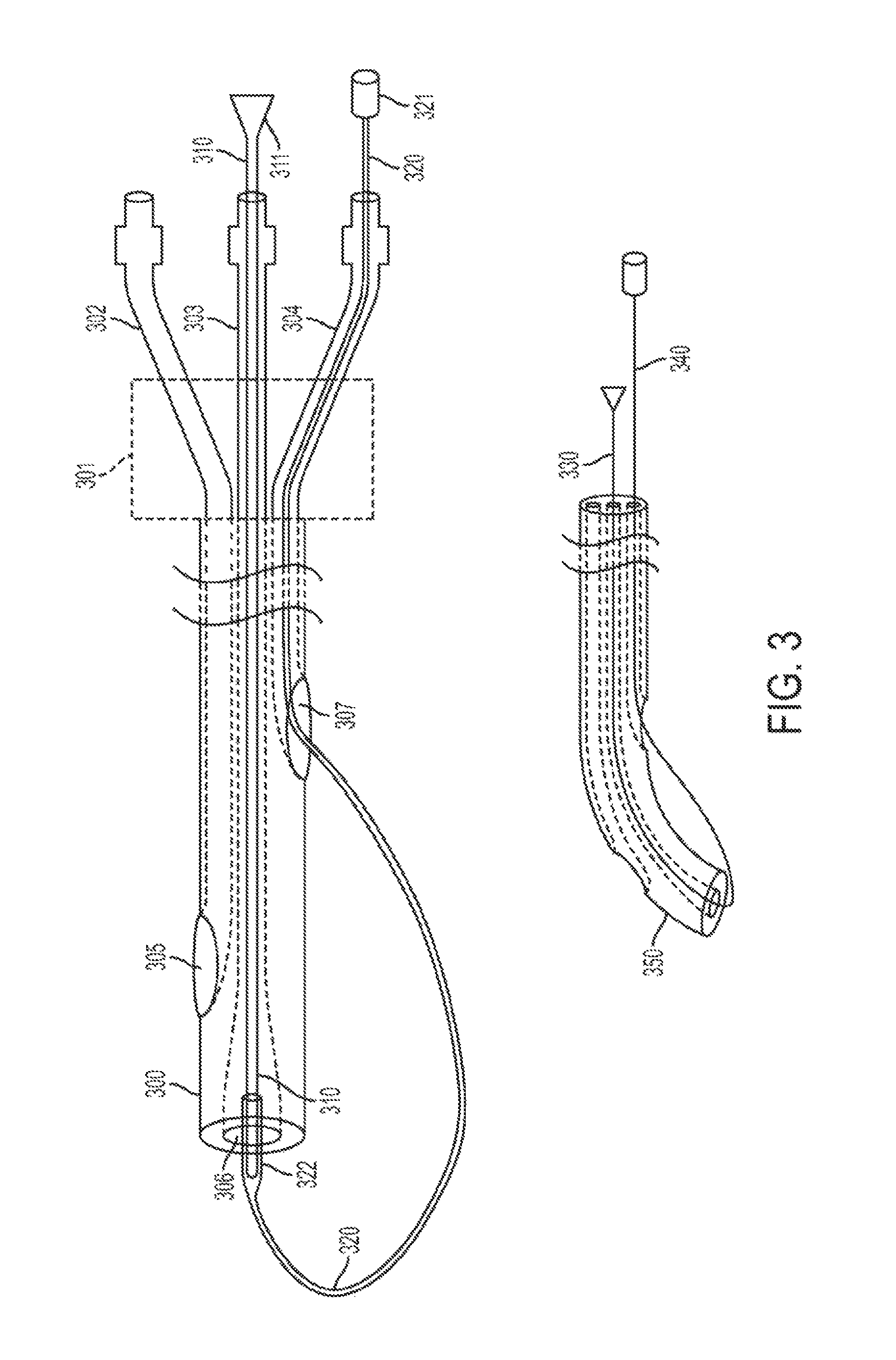
According to another embodiment of the present invention, a steering device for a catheter that has a plurality of lumens with spaced distal openings includes a stylet for disposition within one of the plurality of lumens, and a steering member for disposition within a different one of the plurality of lumens. In the installed position, the stylet and the steering member are connected together at respective distal ends such that a portion of the steering member is disposed outside of the distal end of the catheter.
There has thus been outlined, rather broadly, certain embodiments of the invention in order that the detailed description thereof herein may be better understood, and in order that the present contribution to the art may be better appreciated. There are, of course, additional embodiments of the invention that will be described below and which will form the subject matter of the claims appended hereto.
In this respect, before explaining at least one embodiment of the invention in detail, it is to be understood that the invention is not limited in its application to the details of construction and to the arrangements of the components set forth in the following description or illustrated in the drawings. The invention is capable of embodiments in addition to those described and of being practiced and carried out in various ways. Also, it is to be understood that the phraseology and terminology employed herein, as well as the abstract, are for the purpose of description and should not be regarded as limiting.
As such, those skilled in the art will appreciate that the conception upon which this disclosure is based may readily be utilized as a basis for the designing of other structures, methods and systems for carrying out the several purposes of the present invention. It is important, therefore, that the claims be regarded as including such equivalent constructions insofar as they do not depart from the spirit and scope of the present invention.
BRIEF DESCRIPTION OF DRAWINGS
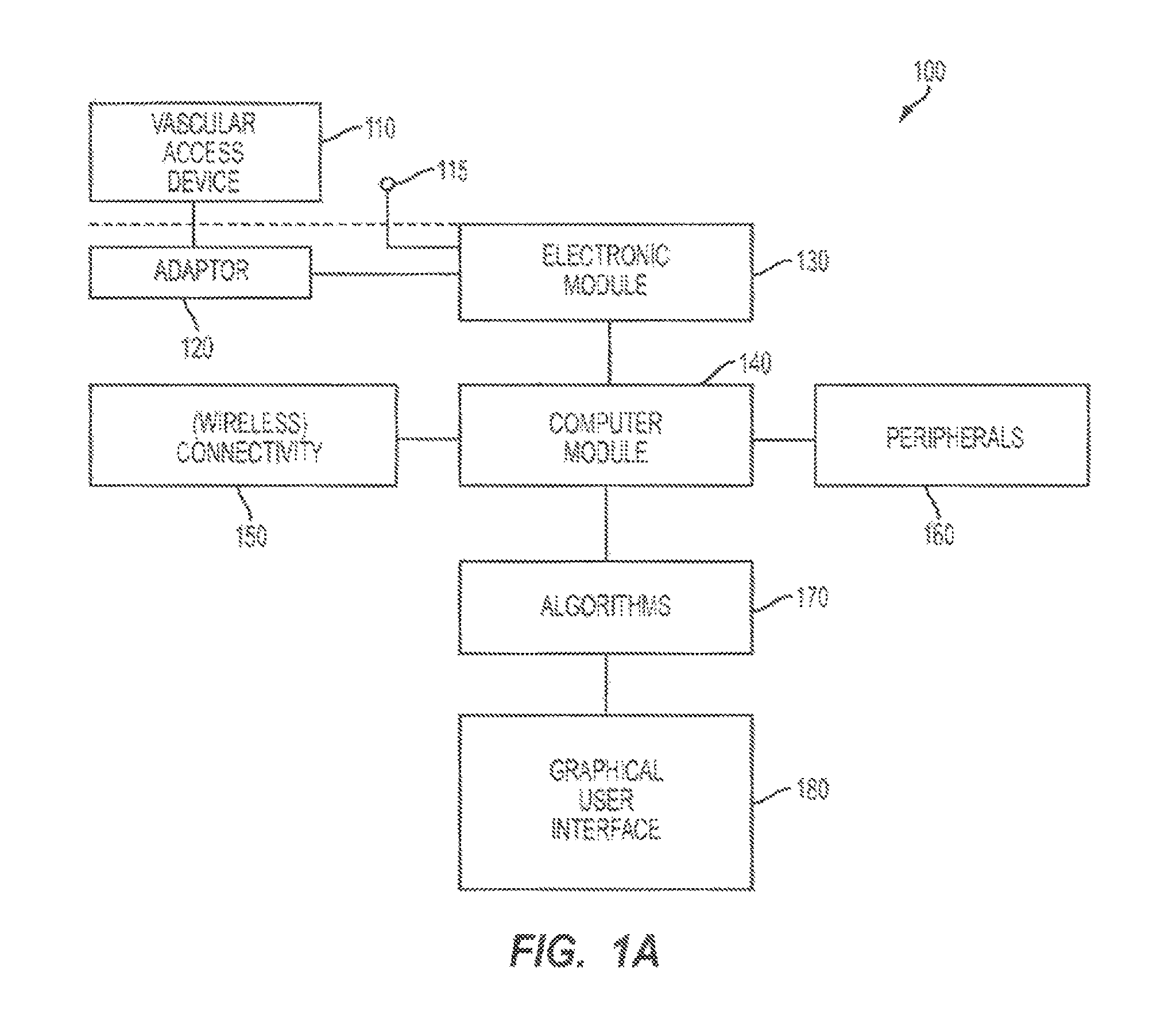
FIG. 1A is a block diagram that depicts an apparatus according to an embodiment of the present invention.
FIG. 1B is a block diagram of an electronic module for acquisition and processing of endovascular electrocardiogram according to an embodiment of the present invention.
FIG. 2 depicts an adaptor for an endovascular device according to an embodiment of the present invention.
FIG. 3 depicts a catheter steering device according to an embodiment of the present invention.
FIGS. 4A, 4B, 4C, and 4D depict electrode configurations that provide optimal acquisition of endovascular electrocardiogram according to various embodiments of the present invention. FIG. 4A depicts a single lead configuration, FIG. 4B depicts a modified 3-lead configuration with monitoring and guiding capabilities, FIG. 4C depicts a telemetry configuration with a single grounded lead, and FIG. 4D depicts one use of ECG monitors for guiding endovascular devices.
FIG. 5 illustrates exemplary electrocardiogram signal amplitudes at different locations in the central venous system.
FIG. 6 illustrates exemplary electrocardiogram signal power spectra at different locations in the central venous system.
FIG. 7 illustrates exemplary electrocardiogram signal electrical energy distribution at different locations in the central venous system.
FIG. 8 depicts a graphical user interface according to an embodiment of the present invention.
FIG. 9 depicts a graphical user interface according to another embodiment of the present invention.
FIGS. 10A and 10B depict an exemplary printouts for the information displayed by the graphical user interface, according to an embodiment of the present invention.
FIG. 11 is a block diagram for a computer-based method for positioning an endovascular device in or near the heart using electrocardiogram signals.
FIG. 12 illustrates another decision support algorithm for a computer-based method for positioning an endovascular device in or near the heart using electrocardiogram signals, according to an alternative embodiment.
FIG. 13 illustrates the cardiac conduction system of the heart.
FIG. 14 illustrates electrical signal propagation in the conduction system of the heart.
FIG. 15 illustrates electrical activity in the cardiovascular system due to neuronal control system.
FIG. 16 illustrates a framework for analyzing the endovascular electrography signals, according to an embodiment of the present invention.
FIG. 17 illustrates several embodiments for electrogram waveform processing.
DETAILED DESCRIPTION
The invention will now be described with reference to the drawing figures, in which like reference numerals refer to like parts throughout.
Embodiments of the present invention advantageously provide an inventive apparatus(es), computer-based data processing algorithms and methods for obtaining and using endovascular ECGs in a number of clinical applications and settings. For example, once device can be used to guide endovascular devices in and around the heart, e.g., guiding central venous access devices in the superior vena cava, right atrium, and right ventricle. Such central venous access devices may include central venous catheters (CVC), peripherally inserted central catheters (PICC), implantable ports, hemodialysis catheters, tunneled catheters and others. Other devices which may benefit from guidance with the inventive apparatus are temporary pacemaker leads placed through the central venous system. Catheters and guidewires used in left heart procedures may also benefit from the present invention by decreasing the amount of contrast and radiation required to guide these devices in position. In another example, the apparatus can be used for minimally invasive monitoring and assessing heart conditions based on its electrical activity, e.g., assessing preload in a heart cycle or monitoring ST segments and T-waves in congestive heart failure.
In one aspect of the invention, an apparatus is described consisting of sterile adaptors, an electronic module for signal acquisition, a computer module, software, and peripheral devices and connections. In one embodiment, the electronic module for signal acquisition can be dedicated to acquiring and processing endovascular electrical signals generated by the body (endovascular ECG), in another embodiment the electronic module can be dedicated to acquiring and processing endovascular ECGs as well as skin ECGs.
In one embodiment, the electronic module and the computer module can be separate modules, in another embodiment they can be integrated in the same module and enclosure, and yet in another embodiment they can communicate with each other via a wireless connection, such as Bluetooth. In one embodiment, the apparatus can contain an integrated printer, while in another embodiment the printer can be external and attached to the apparatus and the apparatus connected via network, e.g., wireless to other devices. In yet another embodiment the apparatus can be used for telemetry and for transmitting the endovascular electrograms to a remote location, e.g., via a telephone line, Internet, and/or wireless phone. Any combination of embodiments mentioned above is also possible.
In another aspect of the invention, various configurations allow the connection of endovascular devices, such as central venous access devices, to the electronic module for signal acquisition and processing. In one embodiment, the device consists of a connecting wire with two ends and special connectors at each end. At one end, the wire can be connected to a metal or nitinol guidewire or stylet as commonly available on the market. At the other end, the wire can be safely connected to the electronic module. In another embodiment, the device includes a coated guidewire, e.g., made of nitinol or stainless steel with uncoated distal and proximal ends and cm markings. In such an embodiment, the coated guidewire is inserted endovascularly, while the connecting wire is connected to the proximal end of the coated guidewire. In another embodiment, the device includes a catheter-syringe adaptor provided with an electrical connecting wire. At one end, the electrical connecting wire is in contact with the fluid, e.g., saline flowing within the catheter syringe adapter. At the other end the connecting wire can be connected to the electronic module.
In another aspect of the invention, various electrode configurations allow for the optimal acquisition of endovascular ECGs. In one embodiment, a single lead is used to provide information about the tip location of an endovascular device within the vasculature. In another embodiment a modified three lead configuration is used to provide simultaneous 3-lead monitoring of the heart activity at the same time with providing tip location information. In another embodiment a modified single lead configuration plus ground is used for telemetry and transferring information from the tip of the catheter remotely.
In another aspect of the invention algorithms are introduced for the analysis of the ECG waveforms and for supporting decision making based on these waveforms. These algorithms discriminate between different locations in the vasculature and assess body functions (systemic and at specific locations in the body), in particular heart functionality. In various embodiments, these algorithms use time domain analysis of waveforms: morphologic, for example shape; statistic, for example behavior.
In other embodiments, the algorithms use frequency domain analysis of waveforms: morphologic, for example shape; statistic, for example behavior. In further embodiments, signal energy analysis in time and frequency domains is also performed, morphologic and statistic. Fuzzy, statistical, and knowledge-based decision making are also contemplated by the present invention as decision support tools.
In another aspect of the invention, a user interface is provided that advantageously simplifies interpretation of data and workflow. In one embodiment the user interface includes simplified graphics showing the location in the vasculature and in the heart of the tip of the endovascular device in use without showing any of the ECG waveforms. In another embodiment, the user interface shows, in real-time, the change in location of the tip of the endovascular device in use.
In another aspect of the invention, several inventive methods are presented which use the apparatus described herein in clinical applications. In one embodiment, a computer-based method is provided that guides central venous catheters (CVC, PICCs, hemodialysis, implantable ports, and others) using stylets, guidewires and saline solution to the superior vena cava, inferior vena cava, the right atrium, and the right ventricle. This method is advantageously less sensitive to patients with arrhythmias than the prior art, and represents an alternative to chest X-ray confirmation of tip location of central venous catheters in most clinical cases. In another embodiment, a computer-based method is provided that guides coated guidewires in the right and left heart. In another embodiment, a computer-based method is provided that guides the placement of temporary pacemaker leads through the central venous system. In another embodiment, a method is provided that is minimally invasive and monitors preload using depolarization and heart rhythms. In another embodiment, a method is provided that is minimally invasive and monitors arrhythmias using P-wave analysis. In another embodiment, a method is provided that is minimally invasive and monitors heart failure using ST segment and T-wave analysis.
FIG. 1A is a block diagram that depicts an apparatus according to an embodiment of the present invention.
The apparatus 100 can be attached through an adaptor (120) to a large variety of commercially available and custom designed vascular access devices (110). Examples of such devices are: central venous catheters (CVC), peripherally inserted central catheters (PICC), implantable ports, tunneled catheters, hemodialysis catheters, guiding catheters for pacemaker leads, guidewires used for coronary and other vascular interventions, guiding catheters for coronary and other vascular interventions, stylets, syringe needles, and others. If the vascular access devices is a stylet, a guidewire, or a syringe needle, its material must be sufficiently electrically conductive, e.g., stainless steel or nitinol. In such a case the hook or the alligator clip adaptor according to the present invention should be used. If the vascular access devices is a catheter, than saline should be used to establish a conductive path through one of the catheter's lumens. In such a case, the syringe-catheter adaptor according to the present invention should be used.
The electronic module (130) receives electrical signals from the adaptor and from one or more other electrodes placed on the patient's skin (115). Alternatively, more than one adaptor can be used at the same time to connect to more than one endovascular device in order to provide different electrical signals to the electronic module. The use of skin electrodes is optional in certain device configurations. The electronic module processes the electrical signals and transmits them to a computer module (140) for further processing and other functions. In one embodiment the electronic module and the computer module can be packaged separately, in another embodiment they can be integrated in the same package. In one embodiment the connection between the electronic module and the computer module can be hardwired, in another embodiment it can be wireless, e.g., using Bluetooth.
The computer module processes the signals from the electronic module applying algorithms (170) as described by the current invention. The computer module can also be connected to peripherals (160), e.g., a printer or a label printer and storage devices and provides connectivity including wireless connectivity (150) to other computers or to the internet. The storage device can be used to store a database of know ledge and information regarding the application at hand. The connectivity interface can be used to update this database remotely with newest relevant knowledge and information, e.g., new clinical cases, new findings regarding the relationship between electrograms and heart conditions. The computer module supports a graphical user interface (180) optimized for the purpose of the clinical application at hand.
FIG. 1B is a block diagram of an electronic module (2) for acquisition and processing of endovascular electrocardiogram according to an embodiment of the present invention.
The patient connector interface (10) allows for connecting electrical leads to the patient (5). Any combination of skin electrodes and/or electrical connections to endovascular devices using the adaptors discussed above can be used. In one embodiment, the amplifier (20) is a four stage amplifier with variable gain, which can amplify electrical signals coming through the patient cable, for example, typical of electrocardiographic values. The analog-to-digital converter (30) converts the signals in digital format readable by the microprocessor (40). Any number and configurations of microprocessors, microcontrollers, or digital signal processors can be used to implement the micro-processing function (45).
In one embodiment, a microcontroller is responsible for controlling the serial communication with a computer module (90) via the serial interface (70) or via the wireless interface (80) and a digital signal processor (DSP) is responsible for implementing one or several of the inventive algorithms described herein. Alternatively, a single processor (46) can be used for both communication and processing.
The micro-processor (40) also receives commands from the computer module (90) and controls different elements of the electronic module, e.g., the amplifier (20) accordingly. The patient isolation block (50) decouples electrically the power (60) and the serial communication channel (70) from the patient interface (10) in order to ensure patient protection to electrical shock. In one embodiment the isolation block (50) can consists of a transformer and/or couplers, e.g. optical couplers.
FIG. 2 depicts an adaptor (200) for an endovascular device according to an embodiment of the present invention. Vascular access devices like catheters, syringes, syringe needles, stopcocks, infusion pumps and others connect to each other through standard connections. For example, in FIG. 2 such a standard connection between two devices is illustrated on device (201) by the luer (202) with inner diameter (203) and outer diameter (204), and on device (250) by threaded port (251) with inner diameter (252) and fluid opening diameter (253). The threaded port (251) and the luer (202) allow for connecting the two devices (201, 250) by threading, attaching, coupling, etc., the port (251) into the luer (202).
The adaptor (200) has a body (220) with two ends (226, 227) with a length 225, and is made, for example, of strong biocompatible plastic material with some degree of elasticity. End (227) has a shape of a cone. In one embodiment, end (227) has an elastic sealing portion (228) such that end (227) can easily fit in the luer (202) of device (201) to seal the connection for fluid flow. The other end (226) is in the shape of a standard luer, such as, for example, luer (202) of device (201). The threaded port (251) of the device (250) can be connected to end (226) of the adaptor (200). The cone piece (227) also allows a connection to a device that does not have a luer. The stand-alone cone piece (270) allows a connection between two devices with different accessible diameters. The end (227) of adaptor (200) has a diameter (223) and fits inside the diameter (272) of the cone piece (270). The end (271) of the cone piece (270) fits in a simple catheter end portion (261) with a diameter (262) of a typical device (260). For example, device (260) can be a catheter for an implantable port.
In one embodiment, device (201) is a syringe needle, and device (250) is a syringe. Fluid, e.g., a conductive electrolyte, flows through adaptor (200) through a central inner bore or lumen (222) having a certain diameter, and provides a fluid path between the devices (250, 201). A conductive metal ring (240) is attached to a portion of the substantially cylindrical surface of lumen (222) and, preferably, induces very little perturbations to the fluid flow. For example, the metal ring (240) may be disposed within a recessed portion of the substantially cylindrical surface of the lumen (222). One end (230) of a conductive wire (233) is electrically coupled to the metal ring (240); in one embodiment, the end (230) is soldered to metal ring (240). In another embodiment, the end (230) is captured between the surface of the lumen (222) and the metal ring (240), and the end (230) and the metal ring (240) maintain good electrical contact through mechanical pressure. The wire (233) may be bare or insulated. In a preferred embodiment, the metal ring (240) is fixedly attached to the surface of lumen (222) using, for example, adhesive, an interference fit, a press fit, etc., while in other embodiments, the metal ring (240) may be removably attached to the surface of lumen (222), free-floating, etc.
The wire (233) passes through a channel (231), which extends from the lumen (222) to an opening in the outer surface of the body (220). Epoxy (232), or other suitable material, may be used to seal the opening of the channel (231), as well as to provide a strain relief for the wire (233). The metal ring (240) may be advantageously disposed adjacent to the channel (231) to provide additional sealing. Thus, the metal ring (240), the wire (233), the channel (231) and the epoxy (232) provide a sealed, electrical connection to the fluid flowing through the adaptor (200). A connector (234) may provide a standard electrical connection to the electrography system; a non-terminated wire may also be used. In one embodiment, the wire (233) terminates at the opening of the channel (231) and the connector (234) is attached directly to the body (222), while in another embodiment, the wire (233) extends through the opening of the channel (231) and the connecter (234) is attached to the free end of the wire (233).
In one embodiment, the substantially cylindrical surface of lumen (222) is tapered along the longitudinal direction. This taper may extend along the entire length of lumen (222), or restricted to a certain portion thereof. For example, the surface of lumen (222) may be cone-shaped and have a larger diameter at the proximal end, or, alternatively, the larger diameter may be located at the distal end.
In one example, device (201) is a syringe needle that is inserted into a lumen of a catheter for an implantable port, and device (250) is a syringe. The syringe is filled with saline, which is then injected into the catheter through the adaptor (200). Thus, the adaptor (200) becomes filled with saline solution, and, because the conductive metal ring (240) is in contact with saline and the conductive wire (233), an electrical connection is established between the catheter lumen and the wire (233). In this way, the electrical signal at the tip of the catheter may be measured through the saline solution. Other electrically conductive solutions may also be used to obtain the endovascular electrogram using the adaptor (200). In another embodiment, the adaptor (200) may be used with infusion pumps, as well as other types of power injections. In an alternative embodiment, the adaptor (200) does not include the metal ring (240), and the electrically conductive ending (230) is in direct contact with the electrolyte.
FIG. 3 illustrates a catheter steering device according to an embodiment of the present invention. In this embodiment, the catheter (300) is a triple lumen catheter and the distal end of each of the lumens is spaced with respect to each other. The catheter steering device can be used with any catheter having two or more lumens with spaced distal lumen openings. The open end of one lumen (306) of catheter (300) is at the very distal end of the catheter, another end or opening of a lumen (305) is spaced back from the distal end and the end or opening of the third lumen (307) is spaced back compared to the second end (305). The distance between the open end (306) and the end (307) is typically from one to several centimeters.
Several types of catheters have multiple lumens with spaced ends, and the inventive steering device can accommodate such catheters. For example, in the case of a peripherally inserted central catheter, the typical length of a catheter is 50 to 60 centimeters and the spacing between the distal lumen ends (305, 306, and 307) is from one to several centimeters. A hemodialysis catheter with two lumens can typically be 20 to 40 centimeters in length, with one to several centimeters spacing between the distal ends of the two lumens. A multi-lumen central venous catheter (CVC) can typically be 15 to 25 cm in length with spacing between distal ends or openings of the lumens being from several millimeters to several centimeters.
At the proximal end, the catheter has a catheter hub (301) which splits the three lumens and connects each of them with a luer (302, 303, 304). The inventive catheter steering device includes a stylet (310) with a handle (311) at the proximal end to allow for pushing, pulling, and removal after use, and a steering member (320) which connects to the distal end of the stylet (322) and which can be fed back into a distal lumen opening of one of the other lumens, such as, for example, lumen (307). The steering member (320) returns to the proximal end of the catheter through the catheter lumen and exits at the proximal end through the luer corresponding the respective lumen (304). So disposed, the steering device is in the installed position. In one embodiment, the member (320) has a handle (321) which can be used to pull the member through the lumen. In another embodiment, the handle (321) is detachable from the member (320).
The member (320) may be polyurethane, silicone, PTFE, or other similar materials. In different embodiments, the member (320) may be any kind of biocompatible thread, e.g., surgical thread. In another embodiment, the member (320) is stainless steel wire. In one embodiment, the stylet is provided pre-inserted into one of the catheter lumens, typically the central lumen with the most distal opening (306) with the member 320 attached at the distal end of the stylet (322) and pre-inserted into the lumen (304) through the lumen opening (307). In order to steer the catheter, the user pulls the member 320 out of the catheter while preventing the stylet 310 to be pulled into the catheter. Thus, the catheter tip can be bent in a desired direction. This situation is illustrated by the bent catheter tip (350), the member (340) which was pulled back and the member (330) which is its initial position with respect to the catheter. If the stylet (310) or the steering member (320), or both are made of any electrically conductive material, then each or both of them can be used to measure electrical signals or endovascular electrograms at the distal tip of the catheter by connecting their proximal ends to the endovascular electrography system. In one embodiment, the steering member (320) can be tied to the stylet (310) through the opening (307) of the catheter lumen.
In another embodiment, the stylet (310) and the steering member (320) are manufactured as a single component to form an extended steering member that is looped back through the opening (305) of a different catheter lumen. By pulling one of the two ends of the extended steering member coming out through luers (304) and (302), the same effect is achieved and the catheter tip can be bent in a desired direction. In another embodiment, in the case of a double lumen catheter, the stylet (310) can be inserted in one lumen and the steering member (320) can be inserted in the other lumen, such that the effect of bending the catheter tip can be achieved by pulling the proximal ends. In a further embodiment, the steering member (320) can be inserted in the lumen (302) and through the opening (305).
FIGS. 4A, 4B, 4C, and 4D depict electrode configurations that provide optimal acquisition of endovascular electrocardiogram according to various embodiments of the present invention.
FIG. 4A depicts a single lead configuration with a reference electrode (410), for example attached to the patient's skin over the right arm and with the other electrode attached through an adaptor to an endovascular device (415). The reference electrode attached to the skin over the right arm is presented in this configuration for illustration purposes only. Other locations of the reference electrode are possible depending on the type of ECG required. The reference electrode over the right arm together with the tip of the endovascular device used with the adaptor can be similar to lead II of a standard ECG. In this case the ECGs obtained from the superior vena cava (401) and inferior vena cava (402) can be optimized. The reference electrode can be attached to the skin in any other location in order to simulate other leads of the standard ECG. The reference electrode can be also connected to adaptors attached to other endovascular devices in order to obtain more local information from within the patient's heart (400).
FIG. 4B depicts a modified 3-lead configuration, with monitoring and guiding capabilities, with 4 electrodes. Three (3) electrodes correspond to the standard ECG electrodes: right arm (RA, 420), left arm (LA, 425), and left leg (LL, 430) used as reference. The fourth electrode is attached through an adapter to the endovascular device (C, 435). In this configuration, the electronic module and the algorithm perform two functions simultaneously: the three standard electrodes (RA, LL, and LL) perform a monitoring function of the heart, while the C electrode (435) allow for recording the ECG at the tip of device.
FIG. 4C depicts a telemetry configuration with a single grounded lead, including the configuration illustrated in FIG. 4A and a ground reference (450). This configuration can be used to transmit ECGs remotely through a telemetry system configuration.
FIG. 4D depicts one use of ECG monitors for guiding endovascular devices. A standard ECG monitor is used having standard inputs RA (465), LA (460), and LL (470). LA (460) is connected to the left arm and LL (470) to the left leg of the patient. The RA input (465) is connected to a switch which can be used be the clinician to switch the RA input (465) between the RA electrode and the catheter (C) electrode 475. Thus either monitoring or guiding of catheter placement can be achieved alternatively.
FIG. 5 illustrates exemplary electrocardiogram signal amplitudes at different locations in the central venous system.
The heart (504), right atrium (501), superior vena cava (SVC) (502), and the inferior vena cava (IVC) (503) are illustrated. Location A is in the upper SVC, location B is in the lower third of the SVC, location C is at the caval-atrial junction, location D is in the right atrium, and location E is in the upper inferior vena cava.
Graph 510 illustrates an ECG waveform as a function of time at recorded at location A. The absolute amplitude of the waveforms is recorded on an amplitude scale (590). In the case of an endovascular ECG, the standard elements of the electrocardiogram are illustrated: the P-wave (560), the R-wave (570), and the T-wave (580). The amplitudes and shape at location A recorded with a lead configuration as in FIG. 4D are similar to an electrocardiogram recoded at the skin level with the same electrode configuration.
Graph 520 illustrates an endovascular ECG depicted at location B. The amplitude at this location is higher than the one at location A but the overall shapes of the waveform are similar at location A and B.
Graph 530 illustrates an endovascular ECG depicted at location C. At location Cat the caval-atrial junction, the amplitude of the waveform is yet higher than the one at location B and the P-wave has dramatically changed becoming higher than the R-wave. This waveform is an indication of the proximity of the sino-atrial node.
Graph 540 illustrates an endovascular ECG depicted at location D. At location Din the right atrium, the amplitudes are similar to location C but the P-wave changes polarity becoming bi-polar. This is an indication that the measurement of the ECG occurs beyond the sino-atrial node.
Graph 550 illustrates an endovascular ECG depicted at location E. At location E in the inferior vena cava, the waveform is similar to the one at location A in terms of amplitude except the P-wave has reverse polarity. The differences in the ECG waveforms at different locations are used by the algorithms introduced herein to discriminate between the corresponding locations and to assess heart and blood vessel functionality.
FIG. 6 illustrates exemplary electrocardiogram signal power spectra at different locations in the central venous system, using a spectral scale (690).
The heart (604), right atrium (601), superior vena cava (SVC) (602), and the inferior vena cava (IVC) (603) are illustrated. Graph 610 illustrates an endovascular ECG spectrum depicted at location A. At location A, the spectrum (610) has the appearance of a single central frequency or single band (660) and with a frequency distribution spectral power and energy similar to those at skin level.
Graph 620 illustrates an endovascular ECG spectrum depicted at location B. At location B the frequency distribution has two major bands and a higher energy and spectral power than the one at location A.
Graph 630 illustrates an endovascular ECG spectrum at location C. At location C, there are multiple (3-4) major frequencies or principal spectral components distributed over a wider range of frequencies (670). This spectral distribution is indicative of the energy distribution around the sino-atrial node. The spectral power and signal energy have increased compared to location B.
Graph 640 illustrates an endovascular ECG spectrum depicted at location D. At location D the spectrum is wider and more broadband indicative of the electrical activity of the right atrium.
Graph 650 illustrates an endovascular ECG spectrum depicted at location E. The frequency spectrum at location E is similar to the one at location A. The differences in the spectral waveforms at different locations are used by the algorithms introduced herein to discriminate between the corresponding locations and to assess heart and blood vessel functionality.
FIG. 7 illustrates exemplary electrocardiogram signal electrical energy distribution at different locations in the central venous system. The heart (704), right atrium (701), superior vena cava (SVC) (702), and the inferior vena cava (IVC) (703) are illustrated. Graphs (710, 720, 730, 740, 750) depict the energy distribution at different locations (A, B, C, D and E, respectively) and the changes in time are used by the algorithms introduced herein to discriminate between the corresponding locations and to assess heart and blood vessel functionality.
Considering FIG. 16 for a moment, a framework for analyzing the endovascular electrography signals according to an embodiment of the present invention is illustrated. The heart is represented by (1600), the superior vena cava by (1601), the inferior vena cava by (1602) and the right atrium by (1603). In this embodiment, there are three regions of interest for placing central venous access devices: the lower third of the superior vena cava or SVC (1605), the caval-atrial junction or CAJ (1606), and the upper right atrium or RA (1607).
The graph (1620) illustrates the electrical energy profile as a function of location in the heart and the graph (1640) illustrates the different electrography waveforms which can be obtained at different locations in the heart. The curve (1630) illustrates the increase of electrical energy detected in each of the regions at the tip of an endovascular catheter advancing from the superior vena cava into the heart. In one embodiment, the energy curve is calculated in time domain, while in another embodiment, the energy curve is calculated in the frequency domain using the frequency spectrum. In one embodiment, the energy is calculated for the actual signal levels, while in another embodiment, the baseline value or other mean values are first subtracted from the signal values before energy calculations. The signal energy or power is calculated in time domain by summing up the squared amplitude values before and/or after baseline subtraction over a determined period of time, e.g., a heartbeat. In the frequency domain, the signal energy or power is calculated by summing up the squared values of the frequency components. In one embodiment, the curve is calculated using the entire electrogram, while in other embodiments, only certain segments of the electrogram are used for the energy calculations, e.g., only the segment corresponding to a "P-wave" of an electrocardiogram. Such a "P-wave" segment is representative of the electrical activity of the sino-atrial node.
Different levels of energy characterize the different locations along the catheter path from the SVC to the heart. These regions can be differentiated in terms of their electrical energy level by using thresholds. Threshold (1631) of energy level defines the beginning of the lower third of the superior vena cava. The energy levels (1621) define the regions in the vasculature of low energy which are distant or further away from the sino-atrial node. The energy levels (1622) between thresholds (1631) and (1632) define the region labeled as the lower third of the superior vena cava (1625 and 1605). The energy levels (1623) between thresholds (1632) and (1633) define the region labeled as the caval-atrial junction (1626 and 1606). The energy levels (1624) between thresholds (1633) and (1634) define the region labeled right atrium (1627 and 1607).
Similarly, the shape and size of the electrogram in graph (1640) relative to a baseline (1650) can be correlated to a location in the heart. Thresholds (1631), (1632), (1633), and (1634) are determined specifically for the type of energy considered for calculations, e.g. the entire electrogram, the P-wave, and/or the S-T segment. Before the lower third of the SVC and corresponding to a relatively low level of energy (1621), the P-wave (1651) and the R-wave (1652) are similar in size and shape with a standard electrocardiogram lead II recorded at the skin level if the right arm standard ECG lead is connected to the catheter and measuring the electrogram signal at the tip of the catheter. In the lower third of the SVC (1605 and 1645), the energy level of the electrogram increases, the electrogram amplitudes increase and the P-wave (1653) increases amplitude and energy relative to the R-wave (1654) to where the P-wave amplitude and energy between half and three quarters of the amplitude and energy of the R-wave. At the caval-atrial junction (1606 and 1646), the energy level of the electrogram increases further, the electrogram amplitudes continue to increase and the P-wave (1655) increases amplitude and energy relative to the R-wave (1656) to where the P-wave amplitude and energy are larger or equal to the amplitude and energy of the R-wave. In the right atrium (1607 and 1647), the energy level of the electrogram increases further, the electrogram amplitudes increase, the P-wave (1657) becomes bipolar and its amplitude and energy relative to the R-wave (1658) start decreasing. These behaviors are quantified, analyzed, and used in order to provide location information regarding the tip of the catheter.
Considering FIG. 17 for a moment, several electrogram waveform processing embodiments are illustrated. Graphs (1710) and (1720) illustrate a P-wave analysis embodiment. Since the P-wave corresponds to electrical activity of the heart generated by the sino-atrial node, the changes of the P-wave are most relevant with respect to determining the proximity of the sino-atrial node in an endovascular approach. Therefore, in order to assess proximity of the sino-atrial node and location in the vasculature, signal analysis methods in time and frequency domains, as well as signal energy criteria can be applied only to the P-wave segment of an electrogram. In graph (1710), the segment designated for the P-wave analysis (1711) starts at moment (1713) and ends at moment (1714). During the period of time between the starting moment and the ending moment of the P-wave segment, the highest amplitude detected corresponds to the P-wave peak (1712). The starting moment (1713) of the P-wave segment analysis can be determined in a number of ways. In one embodiment, the heart beat is calculated and the R-peak is detected as the maximum amplitude of the heartbeat. Going back from each R-peak a certain percentage of the heartbeat, for example between 20% and 30%, determines the moment when the analysis of the P-wave starts (1713). Going back 2% to 5% of the heart beat from each R-peak determines the end of the segment designated for the P-wave analysis (1714). Similarly, in graph (1720), the designated segment for the P-wave analysis (1721) starts at moment (1723) in the heart cycle and ends at moment (1724). The P-wave in this case is bipolar with a positive maximum amplitude (1722) and a negative maximum amplitude (1725) when compared to the baseline (amplitude equals zero). For the P-waveform defined between the starting point (1713 on graph 1710 and 1723 on graph 1720) and the end point (1714 on graph 1710 and 1724 on graph 1720) time-domain and frequency-domain algorithms are applied according to the present invention.
Graph (1730) illustrates the advantages of baseline subtraction prior to signal energy computation. If the signal energy is calculated in time domain as the sum of the squared signal amplitudes over a heartbeat, then the amplitude variations between levels (1731 and 1732) around baseline (1733) may lead to a lower energy level than the signal with amplitude variations between levels (1734 and 1735) whereby the level (1734) is the baseline. The baseline value (1733) is subtracted from the amplitude values (1731 to 1732) and the baseline value (1734) is subtracted from the amplitude values (1734 to 1735). After subtracting the baseline, the sum of squared amplitude values is calculated. Thus, this sum is proportional to the energy of signal variation around the baseline and therefore it is more appropriate to characterize changes in the signal values/behavior.
Graph (1740) shows a typical electrogram waveform with a P-wave (1741) and an R-wave (1742) and a distorted signal with the P-wave covered by high frequency noise (1744) and the R-wave saturated to a maximum value (1743). In the presence of these kind of artifacts (1744 and 1743) it is very difficult and sometimes impossible to recover the original signal (1741 and 1742). Therefore, according to the present invention, an algorithm is used to detect the presence of artifacts and reduce the amount of artifacts as much as possible. If, after reducing the artifacts, the signal cannot be recovered, then the signal is discarded for the computation of signal energy. The presence of artifacts can be detected in time domain by a high value of the derivative and of its integral, a jump in signal energy, a jump in the value of the baseline or in different averages calculated form the signal. In frequency domain, the artifacts can be detected as a jump in the value of the DC component (frequency zero of the spectrum), as the sudden appearance of high frequency components, and in a jump of the spectral power/energy. In the frequency domain, selective filtering can be applied and all components removed, which are not "typical" for the average behavior of the signal. After selective filtering, the signal is reconstructed in the time domain using an inverse Fourier transform in order to allow for verification of the success of the selective filtering.
FIG. 8 depicts a graphical user interface according to an embodiment of the present invention.
Window (810) presents the ECG waveform in real-time as it is acquired by the electronic module using the attached electrode configuration. Window (820) is a reference window and shows a frozen waveform used to compare with the current window. In one embodiment, the reference waveform in window (820) can be obtained through the electrodes connected to the electronic module at a reference location of the catheter and/or using a reference configuration of the skin electrodes. For example, such a reference waveform can be the ECG recorded using an adaptor according to the present invention connected to an endovascular device placed at the caval-atrial junction. In a different embodiment, the reference waveform in window 820 can be a typical waveform at a certain location in the vasculature or of a certain heart condition as it is recorded in a database of waveforms and as it is stored in the storage medium of the computer system. If the electrode configuration allows for simultaneous heart monitoring and recording of electrograms using an endovascular device, window (830) shows one of the standard ECG leads for heart monitoring, while window (810) shows the ECG at the tip of the endovascular devices when connected to an adaptor, such as the ones discussed above.
The icon (870) is a representation of the heart, and the locations A through E (875) illustrate different locations in the heart and vascular system which can be discriminated by analyzing endovascular ECGs in accordance with the methods disclosed herein. As a location in the vasculature is identified by the algorithms, the corresponding place and letter on the icon (875) becomes highlighted or in some other way is made visible to the user. The bars (884), (885), and (886) show signal energy levels. The "E" bar (885) presents the amount of electrical energy computed from the ECG frequency spectrum at the current location of the tip of the endovascular device. The "R" bar (884) presents the amount of electrical energy computed from the ECG frequency spectrum at a reference location. The "M" bar (886) presents amount of electrical energy computed from the ECG frequency spectrum using the monitoring ECG signal from the skin electrodes. The window (840) depicts monitoring information, e.g., heart rate. Patient information (name, date of procedure and others) are shown in window (850). Window (860) contains system control elements like buttons and status information, e.g., scale, scroll speed, system parameters and system diagnostics.
FIG. 9 depicts a graphical user interface according to another embodiment of the present invention.
The icon (920) is a representation of the heart and the locations A through E (930) illustrate different locations in the heart and vascular system which can be discriminated by analyzing endovascular ECGs. As a location in the vasculature is identified by the algorithms, the corresponding place and letter on the icon (930) becomes highlighted or in some other way is made visible to the user. The bars (940), (950), and (960) show signal energy levels. The "E" bar (940) depicts the amount of electrical energy computed from the ECG frequency spectrum at the current location of the tip of the endovascular device. The "R" bar (950) shows the amount of electrical energy computed from the ECG frequency spectrum at a reference location. The "M" bar (960) shows amount of electrical energy computed from the ECG frequency spectrum using the monitoring ECG signal coming from the skin electrodes. The button "Print" (960) allows the user to print the information documenting the case on a printer, for example on a label printer for quick attachment to the patient's chart.
FIGS. 10A and 10B depict an exemplary printouts for the information displayed by the graphical user interface, according to an embodiment of the present invention.
FIG. 10A illustrates a printout (1000) for the case of a catheter tip placement procedure in the lower third of the SVC. The field 1010 depicts the heart icon whereby the letter "B" corresponding to the lower third of the superior vena cava (SVC) is highlighted (1040). Field 1030 depicts the reference ECG waveform recorded at the tip of the catheter at the caval-atrial junction in the proximity of the sino-atrial node. Field 1020 depicts the ECG waveform at the tip of the catheter in the position in which it was placed at the end of the procedure. For FIG. 10A, this location is in the lower third of the SVC and the ECG waveform corresponds to this location. The patient name (1001) and the date of procedure (1002) are also printed.
FIG. 10B depicts a similar printout (1050) except that the final position at the end of the procedure is at the caval-atrial junction at location C (1090) on the heart icon (1060). The "SA Node" field depicts the reference ECG waveform (1080), and the "Final Position" field (1070) shows that the catheter was placed with the tip at the sino-atrial node: the ECG waveform in final location is similar or even identical with the one in the reference location at the sino-atrial node (SA Node). It is known that the proximity of the SA Node indicates a location at the caval-atrial junction. These locations are sometimes considered identical by some clinicians.
FIG. 11 is a block diagram for a computer-based method (1100) for positioning an endovascular device in or near the heart using electrocardiogram signals.
The algorithms are applied to the input signal (1102) (ECG) acquired by the adaptor to the endovascular devices and, optionally, through skin electrodes as well. The Error Detection Block (1105) detects at least three types of error conditions/exceptions, such as, for example, when a defibrillator has been applied to the patient, when a pacemaker is firing excitation pulses and/or when a lead/electrode is off. These errors/exceptions may be handled differently, and the user may be informed about the presence of an exception and the way of handling the exception (1110).
The Pre-Processing block (1115) may amplify the signal, reduce noise, eliminate artifacts, etc. In one embodiment, rescaling the signal to the display range occurs under user control and is not automatic, as with most currently available ECG monitors. Thus, changes in the amplitude of the ECGs are easily noticed. A high-pass filter corrects the baseline and reduces such artifacts as respiratory artifact. Wideband noise suppression may be achieved using a selective filter, e.g., a wavelet transform. Electromagnetic interference with other equipment and the power grid may be suppressed by a notch filter (narrow band filter) centered at 60 Hz or 50 Hz to accommodate domestic or international power supplies. High frequency noise may be suppressed with a low-pass filter, which, in one embodiment, is implemented with variable length averaging, such as, for example, a running window corresponding to a heart cycle, an averaging of the ECG over several consecutive heart cycles, etc. The Adaptive Filtering block (1120) optimizes the filter coefficients by minimizing an error signal.
The Time-Domain Pattern Recognition block (1130) identifies elements of the ECG waveform, their relationship(s) and their behavior(s) in time. An important aspect of the time-domain pattern recognition algorithm in block 1130, as well as of the Frequency Domain Patter Recognition block 1140, is data history. The ECGs are analyzed in real time for certain elements, and, for other elements, a data buffer with an appropriate buffer length is maintained in the memory of the electronic and/or computer modules in order to allow for historic data analysis and prediction based on this analysis. In one embodiment, the data history buffer is several seconds long allowing for the ECG signal corresponding to several heartbeats to be saved in the buffer. A double buffering technique allows the waveform in one buffer to be processed while the second buffer continues to store signals. Thus no signal data are lost while the waveform in one buffer is processed. After data processing on one buffer is completed, the results are sent to the Decision Support Algorithms (1150) and the two buffers switch roles. The length of the buffer accommodates the time duration of data processing in order to ensure that no data are lost. A similar double buffering technique is also applied to the data subject to Frequency Domain Pattern Recognition block (1140).
In the case of an endovascular ECG, elements of interest may include, but are not limited to, one or more of the following: 1. The P, Q, R, S, T, and U waves, their peaks, amplitudes and duration;
2. The duration of the P-R, S-T, and T-P segments/intervals; 3. The elevation of the S-T segment; 4. The variances of the P-P and R-R intervals; 5. The variance of the S-T and of the R-T intervals, etc.; 6. The peak-to-peak values of the P-wave and of the QRS complex; 7. The ratio of the P-wave and R-wave amplitudes and the ratio of the P-wave and QRS complex peak-to-peak amplitudes; 8. The polarity of the P-wave: single positive, single negative, or bipolarity; 9. The derivative of the P-wave, QRS-complex, and T-wave; 10. Temporal average of the R-R interval and the heart beat; 11. Maximum value of the P-wave amplitude/peak and of the P-wave peak-to-peak amplitude over a certain period of time; 12. Maximum value of the R-wave amplitude/peak and of the ORS complex peak-to-peak amplitude over a certain period of time.
Several techniques may be used to derive the information listed above from the ECG waveforms, including, but not limited to, one or more of the following: 1. "Peak detection"; 2. Computation of first derivatives; 3. Running averages along the signal in one heartbeat and along multiple heartbeats; 4. Adaptive thresholding; 5. Auto-correlation.
The Fast Fourier Transform in block (1125) performs a Fast Fourier Transform on a number of ECG samples stored in a buffer of a certain length, e.g., 256, 512, 1024, 2048 or more data samples. The Fourier Transform transforms the waveform from the time domain into the frequency domain.
The Frequency-Domain Pattern Recognition block (1140) illustrates various aspects of pattern recognition performed on the ECGs in the frequency domain, including, but not limited to, one or more of the following: 1. Principal components analysis, i.e., determination of the most significant elements of the frequency spectrum (similarly to determining the morphological elements of the electrograms, e.g., certain waves and segments in time domain); 2. Data compression in order to reduce the amount of computation based on the principal components; 3. Determination of the number and morphology of the principal components, in particular determination if the spectrum has only one, two or multiple main frequencies (frequency bands); 4. Calculation of the spectral power and of the signal energy from the frequency spectrum; 5. Running average along the frequency dimension over a single spectrum in order to reduce wideband noise; 6. Running average along several spectra in order to filter out artifacts; 7. Determination of additional morphological elements of the spectrum, e.g., the maximum frequency, the energy contained in the maximum frequency, the frequency histogram, i.e., what frequencies contain how much energy, the frequency of the highest significant maximum energy peak, etc.; 8. Calculation of behavior and averages over time of the principal components and other parameters determined from the spectral distribution, e.g., determining the maximum value of the signal energy and of the spectral power over a certain period of time; 9. Determine/estimate certain heart conditions based on the spectral analysis. This determination/estimation is also performed in more detailed in the decision support blocks 1150 and 1250.
Several decision support algorithms use the information provided by the time domain pattern recognition and frequency-domain pattern recognition algorithms. In one embodiment, block (1150) supports placing an endovascular device in either the lower third of the SVC or at the caval-atrial junction.
In particular, block 1150 is based on the concept of first reaching the caval-atrial junction during catheter placement. At the caval-atrial junction or near the sino-atrial node the P-wave and other electrical parameters reach a maximum value. At the caval-atrial junction the P-wave is unipolar. After reaching the sino-atrial node at the caval-atrial junction, i.e., the maximum value of the P-peak amplitude and spectral power, the catheter is pulled back several centimeters until the P-wave decreases to half the amplitude reached at the caval-atrial junction. At the location where the P-wave has decreased to half the amplitude as the caval-atrial junction, the catheter is considered to be in the lower third of the superior vena cava. The P-wave peak amplitude or peak-to peak amplitude, as well as the spectral power, is used to map the location in the vasculature to the ECG waveform.
More particularly, after receiving an endovascular ECG signal associated with an endovascular device, the signal is processed, over a plurality of predetermined time periods, to calculate a P-wave amplitude and a spectral power for each predetermined time period. A maximum P-wave amplitude is then determined from the plurality of P-wave amplitudes, as well as an associated maximum spectral power from the plurality of spectral powers. The location at which these maximum values are determined is associated with a predetermined location in or near the heart, such as the cava-atrial junction. The location of the endovascular device is then calculated, for each predetermined time period, based on a ratio of the P-wave amplitude to the maximum P-wave amplitude and a ratio of the spectral power to the maximum spectral power, and the location of the endovascular device is then displayed to the user. Additionally, the polarity of the P-wave and the R-wave amplitude may also be used to determine the location of the endovascular device.
A single criterion or a combination of such criteria can be used to support decision making. In one embodiment, T1, T2, and T3 may be empirically established thresholds which are different for each patient, and the algorithm can use an adaptive loop to adjust the thresholds based on the current measurements. In another embodiment, these thresholds are predetermined.
In alternative embodiments, the ratio between the P-peak/P amplitude or the P-wave peak-to-peak amplitude to the R-peak/R amplitude or to the QRS complex peak-to-peak amplitude can also be used to establish location relative to the sino-atrial node. In one embodiment the P-peak/amplitude must be approximately half of the R-peak/amplitude and the P-wave must be unipolar for the location to correspond to the lower third of the SVC. In another embodiment, the P-wave peak-to-peak must be half of the QRS peak-to-peak amplitude and the P-wave must be unipolar for the location to correspond to the lower third of the SVC.
As discussed above, the results of the decision support algorithms block 1150 may be presented to the user, for example, by high lightening the appropriate location on the heart icon corresponding to the type of ECG identified by the system (1160).
The decision support algorithm block 1250, depicted in FIG. 12, is based on comparing the P-wave, R-wave and P-wave spectral power at the current locations with the values of these parameters determined from the skin electrocardiograms in an equivalent lead, e.g., lead II. Thresholds T1 through T6 are empirical values subject to adaptive adjustments relative to each patient. Each of the criteria or a combination of criteria shown in FIG. 12 can be used.
Other decision algorithms can also be used, in particular related to the level of electrical energy as calculated from the ECG spectrum. In the case of placing endovascular devices, one criterion may be that, at the location corresponding to the lower third of the SVC, the average electrical energy calculated from the endovascular ECG is twice as high as the average electrical energy calculated from the endovascular ECG at skin level or from a skin ECG in a corresponding lead, e.g., lead II.
Method for Placement of Central Venous Catheters
A method of placing a central venous catheter (CVC) is presented below. 1. Estimate or measure the required length of the vascular access device (CVC) for the given patient. 2. If using saline and adaptor (200), go to step 11; if not, proceed as follows. Insert a guidewire into the CVC and flush align the guidewire tip and the catheter tip. Measure the length of the guidewire outside the CVC. This measurement is necessary in order to be able to realign the tip of the catheter and of the guidewire after inserting the guidewire in the vasculature. After taking the measurement, for example with sterile measuring tape or with surgical thread, remove the guidewire from the CVC. 3. Gain vascular access and insert the guidewire for the estimated required length. 4. Insert the CVC over the wire such as to leave outside the CVC the length of the guidewire measured at step 1. Thus the CVC inserted over the wire and the guidewire tip are flush aligned. 5. Connect a sterile electrical adaptor to the guidewire per the instructions for use. 6. Connect the other end of the sterile electrical adapter to the ECG cable of the electrography system. 7. Check that the display of the electrography system indicates desired position of the catheter tip per the instructions for use of the electrography system: in the lower third of the SVC, at the caval-atrial junction or in the right atrium. Typically, the location of the tip of the catheter will be identifiable through the specific shape of the P-wave and of the P-wave relative to the R-wave of the electrogram and/or by the energy levels and thresholds. 8. Adjust the position of the guidewire and CVC by pulling and/or pushing them together as not to change the flush alignment until the ECG waveform on the screen indicates that the desired position has been reached. Correlate the actual inserted length with the estimated length. 9. After the position has been reached, disconnect the electrical adaptor and remove the guidewire. 10. Secure the CVC in location. 11. Continue here if saline and adaptor (200) are used. 12. Gain vascular access and introduce the CVC over the guidewire as currently specified by the existing protocols. 13. Remove the guidewire. 14. Attach the sterile adaptor (200) to the CVC. 15. Attach the electrical connection (234) of the adaptor (200) to the ECG cable of the electrography system. 16. Fill a syringe with saline and connect it to the other end of the adaptor (200). Flush the catheter lumen with saline as to create a conductive saline column all way through the catheter tip. 17. Check that the ECG waveform shown on the display of the electrography system indicates desired position of the catheter tip per the instructions for use of the electrography system: in the lower third of the SVC, at the caval-atrial junction or in the right atrium. Typically, the location of the tip of the catheter will be identifiable through the specific shape of the P-wave and of the P-wave relative to the R-wave of the electrogram and/or by energy levels and thresholds. 18. Adjust the position of the CVC by pulling and/or pushing until the ECG waveform on the screen indicates that the desired position has been reached. Correlate the actual length with the estimated length. 19. After the desired position has been reached remove the syringe and the adaptor (200). 20. Secure the catheter. Method for Placement of Implantable Ports
A method of placing the catheter piece of an implantable port is similar to the method for placing a CVC. The adaptor (200) should be connected to the catheter of the implantable port, and the syringe with saline must be connected to the other end of the universal adaptor. A different electrical adaptor should be connected to a syringe needle placed in the catheter of the implantable port. After reaching the desire position, the catheter should be connected to the implantable port. Method for Placement of Peripherally Inserted Central Catheters Open and Closed Ended
Both open-ended and closed-ended peripherally inserted central catheters (PICC) can be placed as described herein, and the method of PICC placement is similar to the one of placing CVCs. The inventive steering mechanism described herein can be used to bend the tip of the PICC in case the catheter fails to advance in the desired direction.
Method for Placement of Hemodialysis Catheters
A method for placing hemodialysis catheters is similar to the method introduced herein for placing CVCs. The inventive steering mechanism described herein can be used to bend the tip of the hemodialysis catheter in case the catheter fails to advance in the desired direction. Two different guidewires with adaptors (220) can be used for each of the lumens of the hemodialysis catheter as to guide placement of one lumen into the right atrium and of the other lumen at the caval-atrial junction using the electrography system. Each of the lumens of the hemodialysis catheter can be placed independently in sequence or at the same time by connecting the adaptors (220) of each of the lumens with different electrodes of the ECG cable of the electrograph system.
Method for Placing Central Venous Access Devices in Patients with Arrhythmias
Traditionally, patients with arrhythmias have been excluded from procedures of guiding central venous lines placement using the endovascular ECG method because of the lack of visible changes in the shape of the P-wave. The energy criteria for the P-wave analysis described herein can be used to guide the placement of central venous access devices in patients with arrhythmias. In arrhythmia patients, the electrical signals generated by the sino-atrial node have a certain degree of randomness, such that they are not synchronized in order to produce a consistent P-wave. Nevertheless, as previous studies have shown, the electrical activity of the sino-atrial node exists and generates electrical energy of intensities typical to the proximity of the sino-atrial node. In one embodiment, the algorithm uses the energy as measured from the endovascular electrogram in order to map certain location in the vasculature. As such, this algorithm can be used to guide placement in patients with arrhythmias when only the electrical energy is indicative of location but not the shape of the P-wave.
Method for Monitoring Tip Location and Certain Aspects of the Electrical Activity of the Heart
Certain aspects of the electrical activity of the heart can be monitored continuously or intermittently using the devices introduced herein. Either an electrical adaptor or adaptor (200) connected to the electrography system can be used for monitoring. The electrical adaptor can be connected to any stylet or other conductive member introduced in any venous access device or in any arterial device. Adapter (200) can also be connected to any venous or arterial line as long as the infusion of a conductive solution, e.g., saline is possible. Adapter (200) can also be used when electrically conductive fluids are inserted in the body using an infusion pump. Monitoring the tip location and/or certain aspects of the electrical activity of the heart can be performed in a number of clinical situations. 1. Adaptor (200) can be attached to a number of central venous devices post insertion, e.g., at bedside and/or in home care situations: PICCs, CVC, hemodialysis catheters. By connecting the adapter to such a catheter and to an electrography system according to the present invention and by injecting saline into the catheter, the location of the tip of the catheter can be confirmed and/or certain electrically activity of the heart can be monitored during the time the adapter is connected by using methods similar to those introduced above in the present inventions. 2. Adaptor (200) can be connected to an arterial line between the arterial line and the other devices connected to the arterial line. The blood present in the arterial line and in the universal adaptor ensures the electrical connection between the blood and the electrography system. Thus the electrical activity of the heart can be continuously monitored. This is particularly important in the case of monitoring the preload changes which translate in changes of the electrical energy of the heart during the S-T segment of the ECG waveform. 3. Monitoring of the tip location and of the electrical activity of the heart can also be achieved by using the electrography system and connecting the adaptor (200) between a central venous line and a pressure measuring system while performing central venous pressure measurements. 4. In the case of an implanted port, a needle can be inserted into the port chamber and the catheter can be flushed with saline using a syringe filled with saline. An electrical adaptor can be attached to the needle and to the electrography system. The detected electrogram signal will contain information from the skin level where the needle is in contact with the skin and from the tip of the catheter through the injected saline column. Since the impedance of the path to the catheter tip is lower than the one to the skin, the detected signal contains both components, i.e., at the skin level and at the tip of the catheter. By subtracting the skin level signal, the signal at the tip of the catheter can be estimated and thus the tip position and certain electrical activity of the heart according to the algorithms described in the present invention.
FIG. 13 illustrates the cardiac conduction system of the heart, while FIG. 14 illustrates electrical signal propagation in the conduction system of the heart.
These figures illustrate the conductive mechanism of the heart, which explains why the electrical energy distribution within the heart as measured is indicative of specific locations within the heart. Accordingly, local electrical signals, behaviors and energy concentrations can be measured and locations within the heart and blood vessel can be determined more accurately; local heart conditions can also be described more accurately.
The conduction system of the heart begins with the heart's dominant pacemaker, the sino-atrial node (1310). The intrinsic rate of the SA node is 60 to 100 beats/minute. When an impulse leaves the SA node, it travels through the atria along the Bachmann's bundle (1350) and the inter-nodal pathways, on its way to the atrioventricular (AV) node (1320) and ventricles. After the impulse passes through the AV node, it travels to the ventricles, first down to the bundle of His (1330) then along the bundle branches and finally down to the Purkinje fibers (1340). Pacemaker cells in the junctional tissue and Purkinje fibers on the ventricles normally remain dormant because they receive impulses from the SA node. They initiate an impulse only they do not receive one from the SA node. The intrinsic rate of the AV junction is 40 to 60 beats/minute, the intrinsic rate of the ventricles 20 to 40 beats/minute. The different propagation speeds of the electrical impulses are shown in FIG. 14. From the SA node (1410) the impulses propagate through the atrial muscle (1420) and through the ventricular muscle (1460) at app. 0.5 ms, through the bundle branches (1440) and (1450) at app. 2 m/sec, through the Purkinje fibers (1470) at app 4 m/s and through the AV node (1430) at app. 0.05 m/s.
The electrical signals and the electrical energy distribution are advantageously used to identify the proximity of the sino-atrial node and right atrial electrical activity even in the cases of arrhythmia, i.e., in the absence of a coherent P-wave measured by standard skin electrocardiogram. While in some cases of arrhythmia random electrical signal generated in the right atrium is not coherent enough to propagate through the body to the skin, the electrical energy is still present in the right atrium and can be detected by local endovascular measurements as a non-coherent P-wave, i.e., as significant electrical activity in the P-segment of the ECG waveform. Energy measurements are also less sensitive to some local abnormalities in impulse conduction: altered automaticity (arrhythmias), retrograde conduction of impulses, reentry abnormalities.
The electrical signals and the electrical energy distribution are also advantageously used to quantify heart functionality, e.g., preload which is related to the depolarization and extension of the heart muscle.
The electrical signals and the electrical energy distribution are also advantageously used to guide guidewires and guiding catheters through the aorta into the left heart. This method is useful in simplifying the access to the left atrium and to the coronary arteries and in reducing the amount of contrast and radiation needed to guide endovascular devices to those locations. In a different application, the inventive apparatus can also be used to guide catheters, e.g. Swan-Ganz through the right ventricle into the pulmonary artery. Other endovascular devices can be guided and be used to measure endovascular electrical activity in other locations of the cardiovascular system which are identifiable by the cardiograms measured with the new apparatus introduced in the present invention.
FIG. 15 illustrates electrical activity in the cardiovascular system due to neuronal control system. Several paths of conduction are related to the mechanism of control of heart (1530) and blood vessel (1520) activity: receptors (1510), e.g., pressure receptors transmit information related to the state of the blood vessels and to the state of the heart to the nervous system through the Medullary centers (1500). The hypothalamus (1540) and the higher centers (1550) are involved in processing and reacting to the information received from the sensors/receptors. In turn they send impulses (1560) back to blood vessels and the heart. By measuring electrical activity related to the control system, information regarding heart conditions can be obtained which could not have been obtained previously.
The many features and advantages of the invention are apparent from the detailed specification, and, thus, it is intended by the appended claims to cover all such features and advantages of the invention which fall within the true spirit and scope of the invention. Further, since numerous modifications and variations will readily occur to those skilled in the art, it is not desired to limit the invention to the exact construction and operation illustrated and described, and, accordingly, all suitable modifications and equivalents may be resorted to that fall within the scope of the invention.
* * * * *
References
D00000
D00001
D00002
D00003
D00004
D00005
D00006
D00007
D00008
D00009
D00010
D00011
D00012

D00013

D00014

D00015

D00016
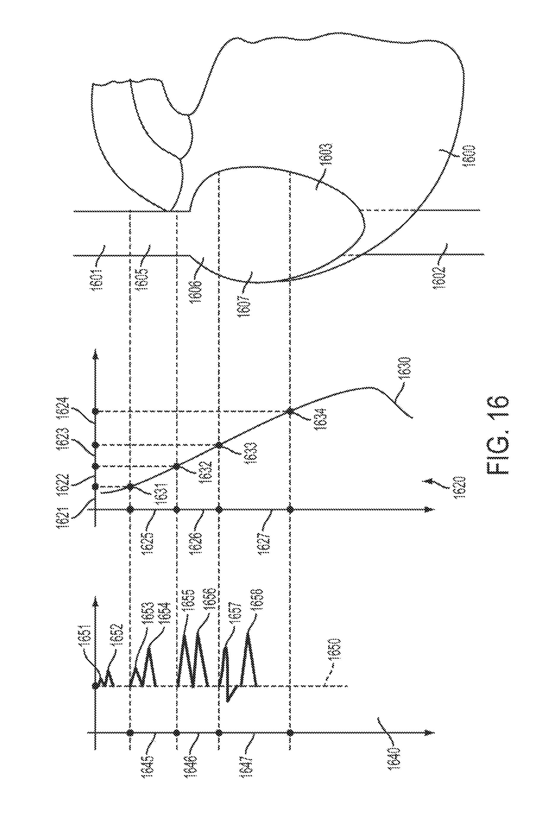
D00017

XML
uspto.report is an independent third-party trademark research tool that is not affiliated, endorsed, or sponsored by the United States Patent and Trademark Office (USPTO) or any other governmental organization. The information provided by uspto.report is based on publicly available data at the time of writing and is intended for informational purposes only.
While we strive to provide accurate and up-to-date information, we do not guarantee the accuracy, completeness, reliability, or suitability of the information displayed on this site. The use of this site is at your own risk. Any reliance you place on such information is therefore strictly at your own risk.
All official trademark data, including owner information, should be verified by visiting the official USPTO website at www.uspto.gov. This site is not intended to replace professional legal advice and should not be used as a substitute for consulting with a legal professional who is knowledgeable about trademark law.