Table elevating device
Tseng , et al. July 16, 2
U.S. patent number 10,349,736 [Application Number 15/725,276] was granted by the patent office on 2019-07-16 for table elevating device. This patent grant is currently assigned to TIMOTION TECHNOLOGY CO., LTD.. The grantee listed for this patent is TIMOTION TECHNOLOGY CO., LTD.. Invention is credited to Kuan-Shu Tseng, Chung-Jen Yang.


| United States Patent | 10,349,736 |
| Tseng , et al. | July 16, 2019 |
Table elevating device
Abstract
A table elevating device includes: a table, formed with a bottom surface, a first side edge and a second side edge spaced away from the first side edge; a support mechanism, vertically disposed for supporting the table, and at least including an electric pushing rod used for driving the support mechanism to be elevated; a driver, served to drive the electric pushing rod to be operated via electric power; and a controller, including a case body having a first case part and a second case part and disposed on the bottom surface, and a control circuit unit electrically connected to the driver; wherein, the second case part is formed with an expansion hole oriented to face the second side edge along an extending direction defined from the interior towards the exterior.
| Inventors: | Tseng; Kuan-Shu (New Taipei, TW), Yang; Chung-Jen (New Taipei, TW) | ||||||||||
|---|---|---|---|---|---|---|---|---|---|---|---|
| Applicant: |
|
||||||||||
| Assignee: | TIMOTION TECHNOLOGY CO., LTD.
(New Taipei, TW) |
||||||||||
| Family ID: | 65095986 | ||||||||||
| Appl. No.: | 15/725,276 | ||||||||||
| Filed: | October 4, 2017 |
Prior Publication Data
| Document Identifier | Publication Date | |
|---|---|---|
| US 20190059573 A1 | Feb 28, 2019 | |
Foreign Application Priority Data
| Aug 29, 2017 [CN] | 2017 2 1090501 U | |||
| Current U.S. Class: | 1/1 |
| Current CPC Class: | A47B 9/04 (20130101); A47B 13/10 (20130101); A47B 2200/0041 (20130101); A47B 2200/0056 (20130101); A47B 21/02 (20130101); A47B 13/081 (20130101) |
| Current International Class: | A47B 9/04 (20060101); A47B 13/10 (20060101); A47B 13/08 (20060101); A47B 21/02 (20060101) |
| Field of Search: | ;108/50.01,50.02,147 |
References Cited [Referenced By]
U.S. Patent Documents
| 4440096 | April 1984 | Rice |
| 4711184 | December 1987 | Wallin |
| 6099093 | August 2000 | Spence |
| 6360675 | March 2002 | Jones |
| 6595144 | July 2003 | Doyle |
| 6885796 | April 2005 | Lubkert |
| 7377078 | May 2008 | Golino |
| 7430114 | September 2008 | Rouleau |
| 7892148 | February 2011 | Stauffer |
| 8087737 | January 2012 | Shoenfeld |
| D678847 | March 2013 | Helm |
| 8522695 | September 2013 | Ellegaard |
| 9084475 | July 2015 | Hjelm |
| D753609 | April 2016 | Wetzel |
| 9703278 | July 2017 | Kristensen |
| D820221 | June 2018 | Yang |
| 2006/0176656 | August 2006 | Sullivan |
| 2009/0078167 | March 2009 | Ellegaard |
| 2012/0126072 | May 2012 | Pettersson |
| 2013/0199420 | August 2013 | Hjelm |
| 2014/0177688 | June 2014 | Chang |
| 2015/0246404 | September 2015 | Teraoka |
| 2015/0351262 | December 2015 | Jorgensen |
| 2016/0022031 | January 2016 | Scott |
| 2016/0238263 | August 2016 | Meissner |
| 2016/0309889 | October 2016 | Lin |
| 2018/0014097 | January 2018 | Lin |
| 19506897 | Feb 1995 | DE | |||
| 29804853 | Mar 1998 | DE | |||
| 19907606 | Aug 2000 | DE | |||
Attorney, Agent or Firm: Shih; Chun-Ming HDLS IPR Services
Claims
What is claimed is:
1. A table elevating device, comprising: a table, formed with a bottom surface, a first side edge formed at one side of the bottom surface and a second side edge formed at another side of the bottom surface, wherein the first side edge is spaced away from the second side edge; a support mechanism, disposed for supporting the table at a vertical direction, and at least including an electric pushing rod used for driving the support mechanism to be elevated; a driver, served to drive the electric pushing rod to be operated via electric power; and a controller, including a case body and a control circuit unit disposed in the case body, wherein the case body is disposed on the bottom surface of the table and arranged to be close to the first side edge, and the control circuit unit is electrically connected to the driver; wherein, the case body includes a first case part and a second case part, the second case part is arranged at an opposite side with respect to the first case part and the second case part is formed with an expansion hole, and the expansion hole is oriented to face the second side edge of the table along an extending direction that is defined from the interior towards the exterior and intersects with the second side edge; wherein the first case part is tilted outwardly to be away from the first side edge and downwardly to be away from the bottom surface, and both a length and a height of the first case part along the first side edge and the vertical direction, respectively, are larger than that of the second case part so that the second case part is concealed by viewing from the first case part.
2. The table elevating device according to claim 1, wherein the bottom surface is further formed with two third side edges arranged between the first side edge and the second side edge.
3. The table elevating device according to claim 2, wherein the first side edge of the table is divided into a linear front edge and at least an inclined edge at one side of the front edge, and the two third side edges on the bottom surface of the table are arranged between the inclined edge and the second side edge.
4. The table elevating device according to claim 2, wherein the amount of the support mechanism is two, and the two support mechanisms are disposed at the two third side edges of the table, a supporter is provided on the bottom surface of the table for connecting the two support mechanisms, and the extending direction is defined as passing the supporter then being perpendicular to the second side edge.
5. The table elevating device according to claim 1, wherein a minimum distance defined from a hole edge of the expansion hole to the first side edge is smaller than a minimum distance defined from the expansion hole to the second side edge.
6. The table elevating device according to claim 1, wherein the controller further includes a display screen.
7. The table elevating device according to claim 1, wherein the control circuit unit includes a control circuit board and a plurality of control buttons disposed on the control circuit board, and the plural control buttons are partially exposed on the first case part.
8. The table elevating device according to claim 7, wherein the control buttons are rotary buttons and press buttons.
9. The table elevating device according to claim 1, wherein an expansion circuit unit is disposed in the second case part, the expansion circuit unit includes an expansion circuit board and an expansion connector disposed on the expansion circuit board, the expansion connector is corresponding to the expansion hole and allows an expansion accessory to be connected to the expansion connector via the expansion hole.
10. The table elevating device according to claim 9, wherein the expansion connector is a connector with RJ specification.
Description
BACKGROUND OF THE INVENTION
Field of the Invention
The present invention relates to an elevating device, especially to a table elevating device capable of being used to adjust the height of a desk surface.
Description of Related Art
A conventional device used for elevation, for example applied to adjust the height of a desk, is often driven by a motor, so that a retractable linkage rod mechanism is enabled to upwardly or downwardly displace the desk surface for allowing the height of the desk surface to be adjusted according to the actual needs, thereby meeting various requirements of users.
However, a conventional elevating desk is often provided with basic functions, or provided with other functions such as expansion or optional accessory. For the functions of expansion or optional accessory, an additional accessory is required for achieving the needs, a main control case of the elevating desk is formed with an insertion hole for the purpose of expansion, so that an objective of expanding function can be achieved through inserting the expansion or optional accessory. The conventional main control case is hidden in a location where the user cannot easily touch, the above-mentioned arrangement can prevent the main control case from being damaged by the user or other people and a better appearance can be provided while designing the desk, but the accessory is difficult to be inserted when an expansion is required. For solving the above-mentioned disadvantage, a conventional means for allowing the accessory to be inserted in an operation panel is provided, but the panel is often located close to the desk edge for allowing the user to conveniently operate, the accessory may protrude from the desk edge after being inserted, thus the operation convenience is affected or the accessory may be damaged or even broken while being accidently hit by the user.
Accordingly, the applicant of the present invention has devoted himself for improving the mentioned disadvantages.
SUMMARY OF THE INVENTION
The present invention is to provide a table elevating device, which has advantages of allowing an expansion accessory to be inserted without causing the problems existed in the prior art, and the expansion accessory can be prevented from being exposed and affecting the appearance and can also be protected from being hit or damaged.
Accordingly, the present invention provides a table elevating device, which comprises a table, a support mechanism, a driver and a controller; the table is formed with a bottom surface, a first side edge formed at one side of the bottom surface and a second side edge formed at another side of the bottom surface, wherein the first side edge is spaced away from the second side edge; the support mechanism is vertically disposed for supporting the table, and at least includes an electric pushing rod used for driving the support mechanism to be elevated; the driver is served to drive the electric pushing rod to be operated via electric power; the controller includes a case body and a control circuit unit disposed in the case body, the case body is disposed on the bottom surface of the table and arranged to be close to the first side edge, and the control circuit unit is electrically connected to the driver; wherein, the case body includes a first case part and a second case part, the second case part is arranged at an opposite side with respect to the first case part and the second case part is formed with an expansion hole, and the expansion hole is oriented to face the second side edge of the table along an extending direction defined from the interior towards the exterior.
BRIEF DESCRIPTION OF DRAWING
FIG. 1 is a perspective view according to the present invention;
FIG. 2 is a perspective view showing a controller according to the present invention;
FIG. 3 is another perspective view showing the controller according to the present invention;
FIG. 4 is a plane top view according to the present invention;
FIG. 5 is a plane side view according to the present invention;
FIG. 6 is a plane top view showing an expansion accessory being inserted according to the present invention;
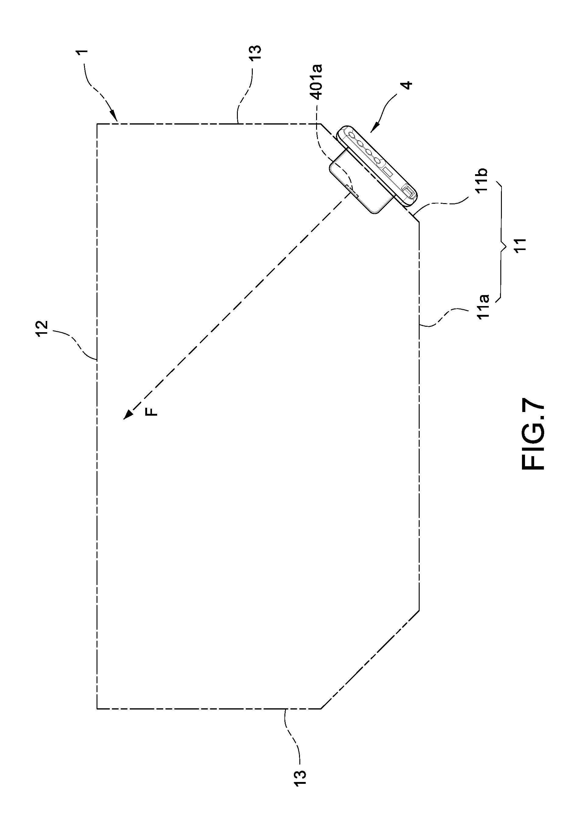
FIG. 7 is a plane top view according to another embodiment of the present invention; and
FIG. 8 is a plane top view according to one another embodiment of the present invention.
DETAILED DESCRIPTION OF THE INVENTION
Preferred embodiments of the present invention will be described with reference to the drawings.
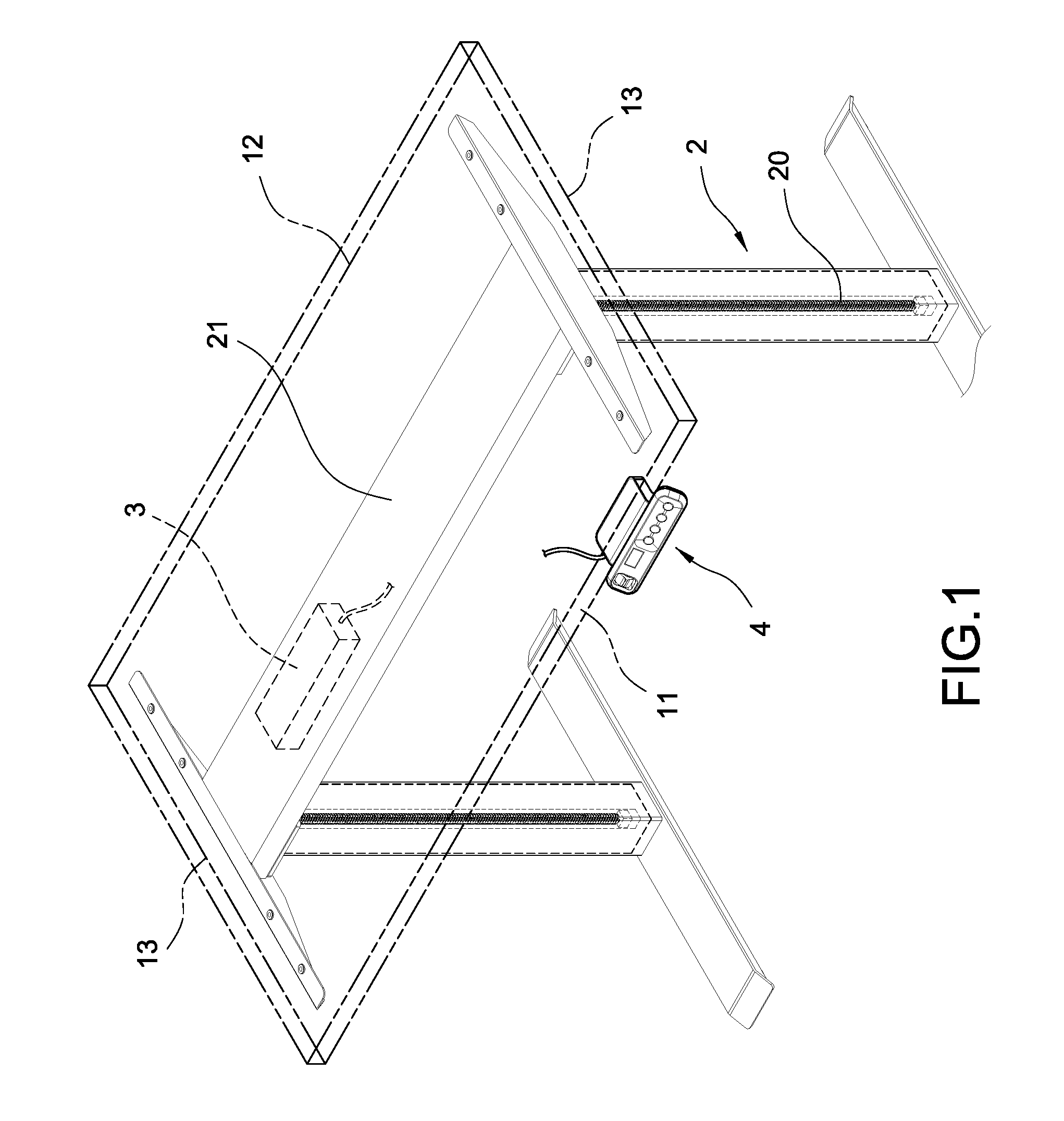
Please refer to FIG. 1, which is a perspective view according to the present invention. A table elevating device comprising a table 1, a support mechanism 2, a driver 3 and a controller 4 is provided by the present invention.
The table 1 can be served as a desk surface, a top surface thereof allows a user to use, and the table 1 is formed with a bottom surface 10 (as shown in FIG. 5) for allowing the above-mentioned components to be disposed thereon. The table 1 is formed with a first side edge 11 arranged at one side of the bottom surface 10, and a second side edge 12 arranged at another side of the bottom surface 10; according to this embodiment, the bottom surface 10 is further formed with two third side edges 13 arranged between the first side edge 11 and the second side edge 12, so that the first side edge 11 is spaced away from the second side edge 12.
As shown in FIG. 1, the support mechanism 2 is vertically disposed for supporting the table 1, and the support mechanism 2 at least includes an electric pushing rod 20. The electric pushing rod 20 is driven by the driver 3 via electric power so as to be operated, thus the support mechanism 2 can be driven to be elevated or descended for adjusting the height of the table 1.
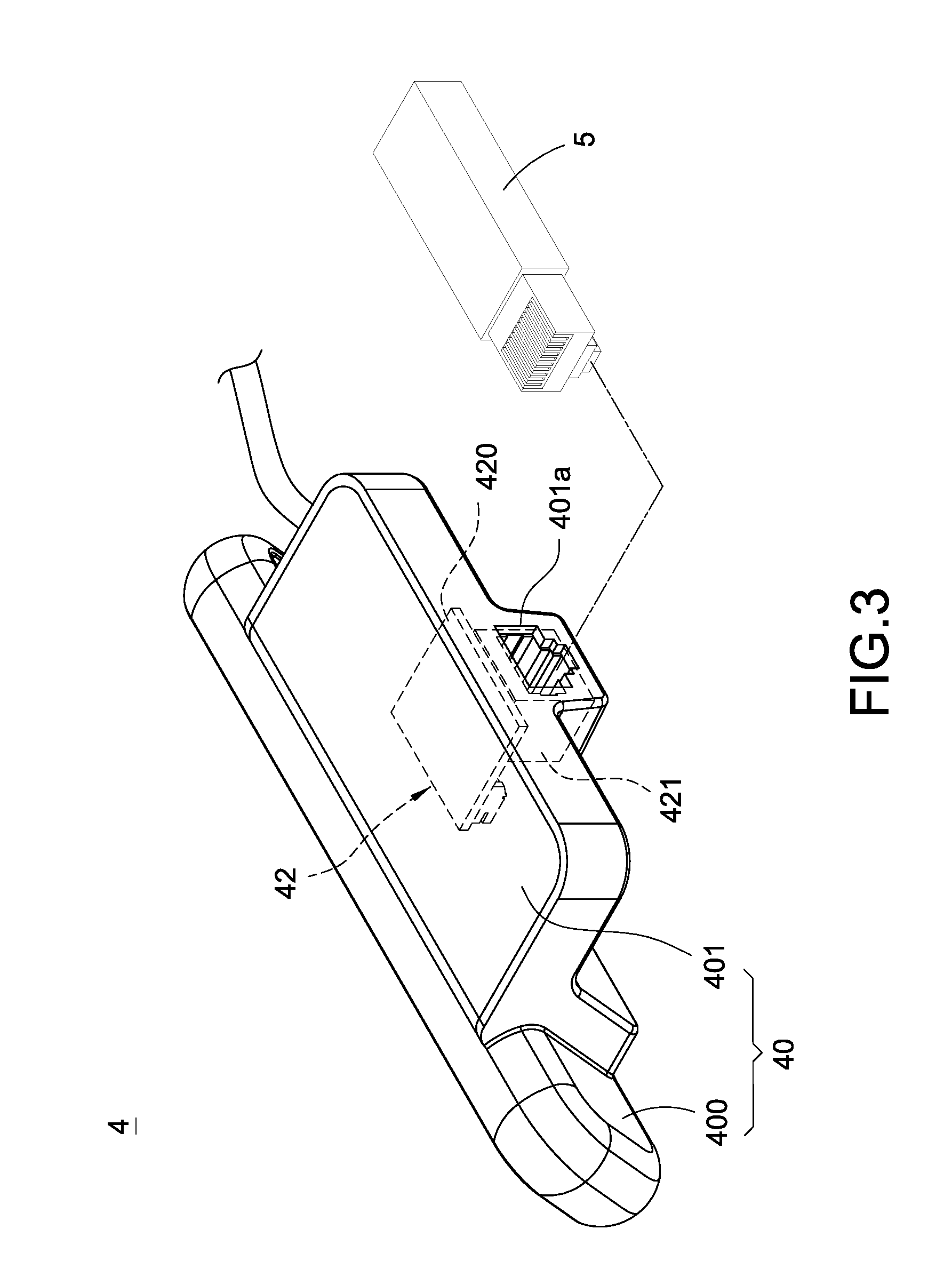
Please refer to FIG. 2 and FIG. 3, the controller 4 includes a case body 40 and a control circuit unit 41 disposed in the case body 40. The controller 4 is disposed on the bottom surface 10 of the table 1 and arranged to be close to the first side edge 11, and the control circuit unit 41 is electrically connected to the driver 3 via a wiring means. Details are provided as follows. The case body 40 includes a first case part 400 and a second case part 401. The control circuit unit 41 includes a control circuit board 410 and a plurality of control buttons 411 disposed on the control circuit board 410, the plural control buttons 411 are partially exposed on the first case part 400 for allowing a user to operate. The control buttons 411 can be rotary buttons 411a and press buttons 411b which are selectively adopted with respect to the actual needs. In addition, the control circuit board 410 is electrically connected to the driver 3, so that when the user operates the control buttons 411, the driver 3 can be correspondingly operated. Moreover, the controller 4 further includes a display screen 400a, the display screen 400a is disposed on the first case part 400 and arranged at the same side as the plural control buttons 411, so that relevant operating information can be displayed for allowing the user to view during the operation.
The second case part 401 is arranged at an opposite side with respect to the first case part 400, and the first case part 400 and the second case part 401 can be integrally formed. An expansion hole 401a is formed on the second case part 401, and an expansion circuit unit 42 is disposed inside the second case part 401. The expansion circuit unit 42 includes an expansion circuit board 420 and an expansion connector 421 disposed on the expansion circuit board 420, the expansion connector 421 is corresponding to the expansion hole 401a and allows an expansion accessory 5 to be connected to the expansion connector 421 via the expansion hole 401a. The expansion connector 421 can be a connector with RJ specification, and the expansion accessory 5 can be served to expand the function of the controller 4 via a wireless transferring means such as a Bluetooth or WiFi.
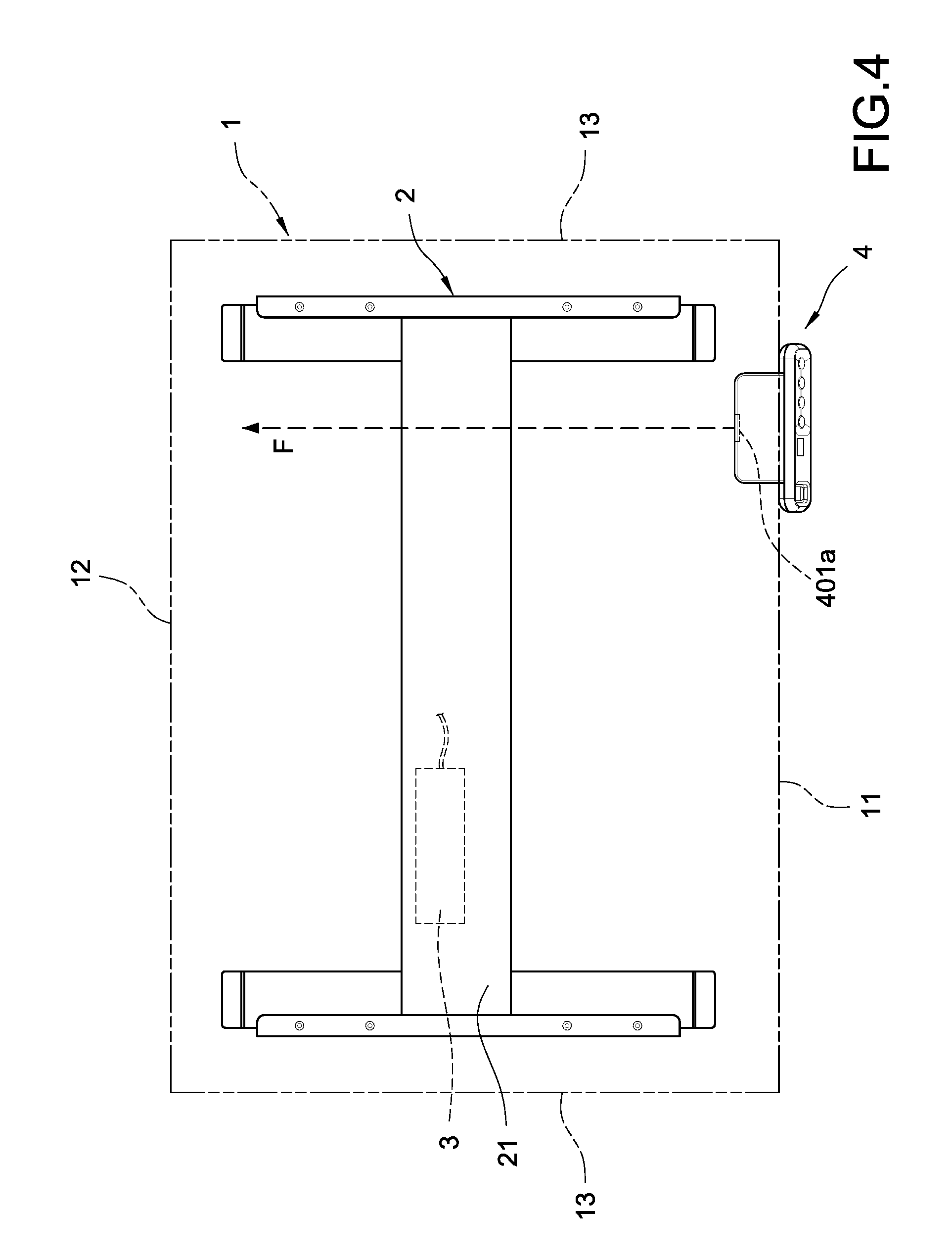
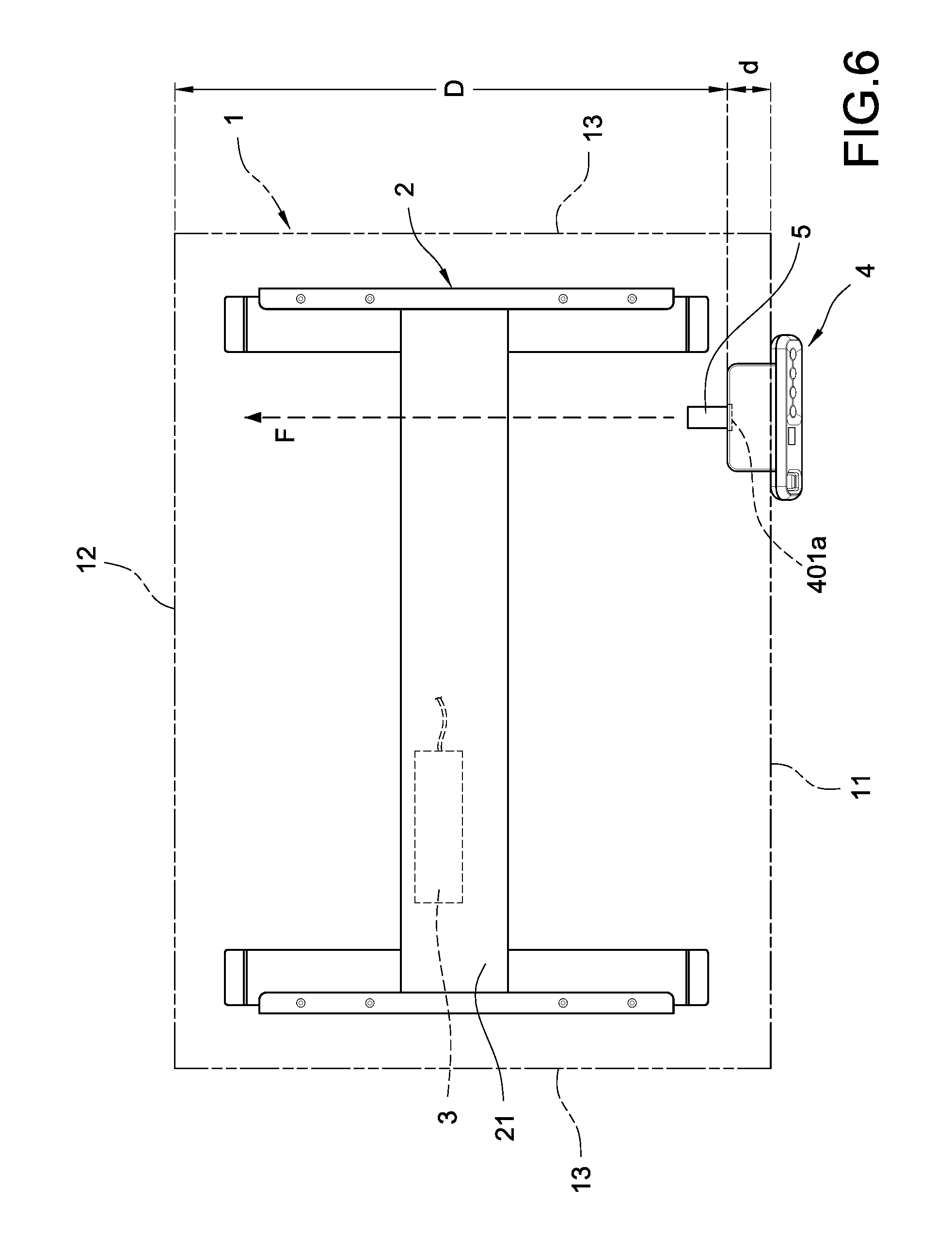
Please refer to FIG. 4 and FIG. 5, which disclose one embodiment of the present invention; the first side edge 11 of the table 1 is in a linear status, and the controller 4 can be disposed at any desired location close to the first side edge 11, so that the expansion hole 401a is able to be oriented to face the second side edge 12 of the table 1 along an extending direction F defined from the interior of the case body 40 towards the exterior and perpendicular to the second side edge 12 after being extended. Moreover, the support mechanism 2 is disposed between the two third side edges 13 of the table 1, and a supporter 21 is provided on the bottom surface 10 of the table 1 for connecting the two support mechanisms 2, and the extending direction F is defined as firstly passing the supporter 21 then being perpendicular to the second side edge 12. Please refer to FIG. 6, with the above-mentioned arrangement, a minimum distance d defined from a hole edge of the expansion hole 401a to the first side edge 11 is obviously much smaller than a minimum distance D defined from the expansion hole 401a to the second side edge 12; as such, when the expansion accessory 5 is inserted in the expansion hole 401a and connected to the expansion connector 421, the assembly for expansion can be simply achieved through the arm of the user to reach the above-mentioned distance d, and a sufficient space can be provided by the above-mentioned distance D for hiding the expansion accessory 5, so that the operation on the table 1 would not be affected and a situation of accidently hitting the expansion accessory 5 can be avoided.
Please refer to FIG. 7, according to another embodiment of the present invention, the first side edge 11 of the table 1 can be divided into a linear front edge 11a and at least an inclined edge 11b at one side of the front edge 11a, and the two third side edges 13 on the bottom surface 10 of the table 1 are arranged between the inclined edge 11b and the second side edge 12. Accordingly, the controller 4 can still be disposed at any desired location close to the inclined edge 11b, and the inclined edge 11b is relatively spaced from the second side edge 12. Please refer to FIG. 12, according to one another embodiment of the present invention, the first side edge 11 of the table 1 is formed in an arc-shaped status, when the controller 4 is disposed at any desired location close to the first side edge 11, the controller 4 is still relatively spaced from the second side edge 12. As such, according to the two embodiments, there is an enough space for hiding the expansion accessory 5, so that the expansion accessory 5 can be prevented from being exposed and protected from being hit or even damaged.
With the above-mentioned structure, the table elevating device of the present invention is assembled.
Although the present invention has been described with reference to the foregoing preferred embodiment, it will be understood that the invention is not limited to the details thereof. Various equivalent variations and modifications can still occur to those skilled in this art in view of the teachings of the present invention. Thus, all such variations and equivalent modifications are also embraced within the scope of the invention as defined in the appended claims.
* * * * *
D00000
D00001
D00002
D00003
D00004
D00005
D00006
D00007
D00008
XML
uspto.report is an independent third-party trademark research tool that is not affiliated, endorsed, or sponsored by the United States Patent and Trademark Office (USPTO) or any other governmental organization. The information provided by uspto.report is based on publicly available data at the time of writing and is intended for informational purposes only.
While we strive to provide accurate and up-to-date information, we do not guarantee the accuracy, completeness, reliability, or suitability of the information displayed on this site. The use of this site is at your own risk. Any reliance you place on such information is therefore strictly at your own risk.
All official trademark data, including owner information, should be verified by visiting the official USPTO website at www.uspto.gov. This site is not intended to replace professional legal advice and should not be used as a substitute for consulting with a legal professional who is knowledgeable about trademark law.