High-density precursor for manufacture of composite metal oxide cathodes for li-ion batteries
Dai , et al. July 9, 2
U.S. patent number 10,347,909 [Application Number 16/175,093] was granted by the patent office on 2019-07-09 for high-density precursor for manufacture of composite metal oxide cathodes for li-ion batteries. This patent grant is currently assigned to Apple Inc.. The grantee listed for this patent is Apple Inc.. Invention is credited to John David Carter, Hongli Dai, Christopher S. Johnson, Huiming Wu.


| United States Patent | 10,347,909 |
| Dai , et al. | July 9, 2019 |
High-density precursor for manufacture of composite metal oxide cathodes for li-ion batteries
Abstract
The disclosed embodiments relate to the manufacture of a precursor co-precipitate material for a cathode active material composition. During manufacture of the precursor co-precipitate material, an aqueous solution containing at least one of a manganese sulfate and a cobalt sulfate is formed. Next, a NH.sub.4OH solution is added to the aqueous solution to form a particulate solution comprising irregular secondary particles of the precursor co-precipitate material. A constant pH in the range of 10-12 is also maintained in the particulate solution by adding a basic solution to the particulate solution.
| Inventors: | Dai; Hongli (Los Altos, CA), Johnson; Christopher S. (Naperville, IL), Wu; Huiming (San Jose, CA), Carter; John David (Bolingbrook, IL) | ||||||||||
|---|---|---|---|---|---|---|---|---|---|---|---|
| Applicant: |
|
||||||||||
| Assignee: | Apple Inc. (Cupertino,
CA) |
||||||||||
| Family ID: | 53546757 | ||||||||||
| Appl. No.: | 16/175,093 | ||||||||||
| Filed: | October 30, 2018 |
Prior Publication Data
| Document Identifier | Publication Date | |
|---|---|---|
| US 20190067686 A1 | Feb 28, 2019 | |
Related U.S. Patent Documents
| Application Number | Filing Date | Patent Number | Issue Date | ||
|---|---|---|---|---|---|
| 15627853 | Jun 20, 2017 | 10128494 | |||
| 14449987 | Jul 25, 2017 | 9716265 | |||
| Current U.S. Class: | 1/1 |
| Current CPC Class: | H01M 4/364 (20130101); B01J 19/0006 (20130101); C01G 51/50 (20130101); C01G 53/40 (20130101); C01G 53/00 (20130101); C01G 53/50 (20130101); C01G 51/04 (20130101); H01M 4/525 (20130101); B01J 19/0066 (20130101); B01J 19/0013 (20130101); C01G 53/006 (20130101); B01J 19/18 (20130101); C01G 51/006 (20130101); B01J 19/24 (20130101); C01P 2006/12 (20130101); B01J 2219/24 (20130101); H01M 4/505 (20130101); H01M 10/052 (20130101); C01P 2004/61 (20130101); B01J 2219/00177 (20130101); C01P 2004/32 (20130101); C01P 2002/52 (20130101); C01P 2002/50 (20130101); C01P 2002/88 (20130101); C01P 2006/40 (20130101); C01P 2002/72 (20130101); C01P 2004/03 (20130101); B01J 2219/00051 (20130101); C01P 2004/51 (20130101); Y02E 60/10 (20130101); C01P 2006/11 (20130101) |
| Current International Class: | B01J 19/24 (20060101); B01J 19/00 (20060101); C01G 53/00 (20060101); B01J 19/18 (20060101); H01M 4/36 (20060101); H01M 4/525 (20100101); C01G 51/04 (20060101); C01G 51/00 (20060101); H01M 4/505 (20100101); H01M 10/052 (20100101) |
| Field of Search: | ;428/402 |
References Cited [Referenced By]
U.S. Patent Documents
| 5744262 | April 1998 | Cheng et al. |
| 6007947 | December 1999 | Mayer |
| 6077496 | June 2000 | Hiraoka et al. |
| 6677082 | January 2004 | Thackeray et al. |
| 6680143 | January 2004 | Thackeray et al. |
| 6878487 | April 2005 | Cho et al. |
| 7135252 | November 2006 | Thackeray et al. |
| 7205072 | April 2007 | Kang et al. |
| 7238450 | June 2007 | Howard, Jr. et al. |
| 7314682 | January 2008 | Thackeray et al. |
| 7314684 | January 2008 | Kang et al. |
| 7435402 | October 2008 | Kang et al. |
| 7468223 | December 2008 | Thackeray et al. |
| 7655361 | February 2010 | Kim et al. |
| 7732096 | June 2010 | Thackeray et al. |
| 7754384 | July 2010 | Patoux et al. |
| 7897674 | March 2011 | Zaghib |
| 7923149 | April 2011 | Hwang et al. |
| 8148011 | January 2012 | Thackeray et al. |
| 8187746 | May 2012 | Chen et al. |
| 8206852 | June 2012 | Chang et al. |
| 8277683 | October 2012 | Deng et al. |
| 8337727 | December 2012 | Chen et al. |
| 8383077 | February 2013 | Thackeray et al. |
| 8801960 | August 2014 | Ueda et al. |
| 9716265 | July 2017 | Dai |
| 10084187 | September 2018 | Dai et al. |
| 10128494 | November 2018 | Dai |
| 10141572 | November 2018 | Wu et al. |
| 10164256 | December 2018 | Wu et al. |
| 2002/0061444 | May 2002 | Kweon et al. |
| 2002/0114995 | August 2002 | Thackeray |
| 2002/0136954 | September 2002 | Thackeray |
| 2003/0039886 | February 2003 | Zhang et al. |
| 2003/0082445 | May 2003 | Smieth et al. |
| 2004/0029008 | February 2004 | Winterberg |
| 2004/0258836 | December 2004 | Besenhard et al. |
| 2005/0026040 | March 2005 | Thackery |
| 2005/0074675 | April 2005 | Nishijima et al. |
| 2005/0136329 | June 2005 | Howard, Jr. et al. |
| 2005/0265909 | December 2005 | Kajiya et al. |
| 2005/0271948 | December 2005 | Kang |
| 2006/0024584 | February 2006 | Kim et al. |
| 2006/0068293 | March 2006 | Kim et al. |
| 2006/0081818 | April 2006 | Ito et al. |
| 2006/0088767 | April 2006 | Li et al. |
| 2006/0159994 | July 2006 | Dahn et al. |
| 2006/0177739 | August 2006 | Endo et al. |
| 2006/0194118 | August 2006 | Yew et al. |
| 2006/0240326 | October 2006 | Lee |
| 2007/0141469 | June 2007 | Tokunaga et al. |
| 2007/0172739 | July 2007 | Visco |
| 2007/0202407 | August 2007 | Eberman et al. |
| 2008/0057401 | March 2008 | Mori et al. |
| 2008/0090150 | April 2008 | Nakura |
| 2008/0118847 | May 2008 | Jung et al. |
| 2008/0160415 | July 2008 | Wakita et al. |
| 2008/0280205 | November 2008 | Jiang et al. |
| 2008/0311473 | December 2008 | Sasaoka et al. |
| 2009/0092903 | April 2009 | Johnson et al. |
| 2009/0146115 | June 2009 | Xiao et al. |
| 2009/0200510 | August 2009 | Watanabe et al. |
| 2009/0239148 | September 2009 | Jiang |
| 2010/0086853 | April 2010 | Venkatachalam et al. |
| 2010/0086854 | April 2010 | Kumar et al. |
| 2010/0151332 | June 2010 | Lopez et al. |
| 2010/0173197 | July 2010 | Li et al. |
| 2010/0304225 | December 2010 | Pascaly et al. |
| 2011/0014518 | January 2011 | Nakai et al. |
| 2011/0017529 | January 2011 | Kumar et al. |
| 2011/0031437 | February 2011 | Nagase et al. |
| 2011/0052981 | March 2011 | Lopez et al. |
| 2011/0053001 | March 2011 | Babic et al. |
| 2011/0076564 | March 2011 | Yu et al. |
| 2011/0089369 | April 2011 | Patoux et al. |
| 2011/0111294 | May 2011 | Lopez et al. |
| 2011/0111298 | May 2011 | Lopez et al. |
| 2011/0121240 | May 2011 | Amine et al. |
| 2011/0136019 | June 2011 | Amiruddin et al. |
| 2011/0143174 | June 2011 | Kim |
| 2011/0165474 | July 2011 | Im et al. |
| 2011/0171371 | July 2011 | Li et al. |
| 2011/0171539 | July 2011 | Patoux et al. |
| 2011/0200864 | August 2011 | Dai |
| 2011/0200880 | August 2011 | Yu |
| 2011/0223492 | September 2011 | Sakitani et al. |
| 2011/0244331 | October 2011 | Karthikeyan et al. |
| 2011/0294006 | December 2011 | Amine et al. |
| 2011/0294019 | December 2011 | Amine et al. |
| 2012/0040247 | February 2012 | Manivannan et al. |
| 2012/0168696 | May 2012 | Huang et al. |
| 2012/0196176 | August 2012 | He et al. |
| 2012/0282522 | November 2012 | Axelbaum et al. |
| 2012/0295155 | November 2012 | Deng et al. |
| 2013/0004826 | January 2013 | Li et al. |
| 2013/0011738 | January 2013 | Zhou |
| 2013/0101893 | April 2013 | Dai et al. |
| 2013/0149604 | June 2013 | Fujiki et al. |
| 2013/0252107 | September 2013 | Lee et al. |
| 2014/0087065 | March 2014 | Li et al. |
| 2014/0087254 | March 2014 | Li et al. |
| 2014/0087256 | March 2014 | Li et al. |
| 2014/0087261 | March 2014 | Li et al. |
| 2014/0141331 | May 2014 | Lee et al. |
| 2014/0158932 | June 2014 | Sun et al. |
| 2014/0175329 | June 2014 | Palma et al. |
| 2014/0234715 | August 2014 | Fasching et al. |
| 2014/0272563 | September 2014 | Dai et al. |
| 2015/0140421 | May 2015 | Ihara et al. |
| 2015/0171423 | June 2015 | Kim et al. |
| 2015/0243971 | August 2015 | Cho et al. |
| 2015/0311522 | October 2015 | Fang et al. |
| 2016/0036043 | February 2016 | Dai et al. |
| 2017/0092949 | March 2017 | Dai et al. |
| 2017/0214045 | July 2017 | Dai et al. |
| 2017/0263917 | September 2017 | Dai et al. |
| 2017/0263928 | September 2017 | Dai et al. |
| 2017/0263929 | September 2017 | Wu et al. |
| 2017/0346082 | November 2017 | Dai et al. |
| 2018/0062156 | March 2018 | Wu et al. |
| 2018/0079655 | March 2018 | Dai et al. |
| 2018/0083277 | March 2018 | Dai et al. |
| 2018/0083278 | March 2018 | Dai et al. |
| 2018/0114983 | April 2018 | Dai et al. |
| 2018/0114984 | April 2018 | Wu et al. |
| 2018/0123117 | May 2018 | Dai et al. |
| 2018/0215629 | August 2018 | Honma et al. |
| 2018/0257947 | September 2018 | Dai et al. |
| 2018/0294522 | October 2018 | Dai et al. |
| 2018/0351173 | December 2018 | Dai et al. |
| 2019/0027747 | January 2019 | Dai et al. |
| 2019/0074514 | March 2019 | Wu et al. |
| 1588675 | Mar 2005 | CN | |||
| 1702891 | Nov 2005 | CN | |||
| 1770514 | Oct 2006 | CN | |||
| 101150190 | Mar 2008 | CN | |||
| 101223660 | Jul 2008 | CN | |||
| 101284681 | Oct 2008 | CN | |||
| 101694877 | Apr 2010 | CN | |||
| 101734728 | Jun 2010 | CN | |||
| 102110808 | Jun 2011 | CN | |||
| 102299299 | Dec 2011 | CN | |||
| 102368548 | Mar 2012 | CN | |||
| 102484249 | May 2012 | CN | |||
| 102544575 | Jul 2012 | CN | |||
| 102646831 | Aug 2012 | CN | |||
| 102683666 | Sep 2012 | CN | |||
| 102751481 | Oct 2012 | CN | |||
| 102881891 | Jan 2013 | CN | |||
| 103296249 | Sep 2013 | CN | |||
| 102386381 | Jan 2014 | CN | |||
| 103872302 | Jun 2014 | CN | |||
| 103972493 | Aug 2014 | CN | |||
| 10352063 | Jun 2005 | DE | |||
| 4-267053 | Sep 1992 | JP | |||
| H-10-087327 | Apr 1998 | JP | |||
| 2005-101003 | Apr 2005 | JP | |||
| 2005-289700 | Oct 2005 | JP | |||
| 2009-4311 | Jan 2009 | JP | |||
| 2015-213038 | Nov 2015 | JP | |||
| 10-2002-0063501 | Aug 2002 | KR | |||
| 10-2014-0073856 | Jun 2014 | KR | |||
| 201126798 | Aug 2011 | TW | |||
| 201342695 | Oct 2013 | TW | |||
| WO 2004/045015 | May 2004 | WO | |||
| WO 2004/107480 | Dec 2004 | WO | |||
| WO 2008/069351 | Jun 2008 | WO | |||
| WO 2009/120515 | Oct 2009 | WO | |||
| WO 2010/011569 | Jan 2010 | WO | |||
| WO 2010/139404 | Dec 2010 | WO | |||
| WO 2011/020073 | Feb 2011 | WO | |||
| WO 2011/054441 | May 2011 | WO | |||
| WO 2013/048048 | Apr 2013 | WO | |||
| WO 2014/119165 | Aug 2014 | WO | |||
Other References
|
Zhao et al., "Progress of Research on the Li-rich Cathode Materials xLi2MnO3(1-x)LiMO2(M+Co, Fe, Ni1/2Mn1/2 . . . ) for Li-ion Batteries," Journal of Inorganic Materials, vol. 26(7), pp. 673-679, Jul. 2011. cited by applicant . Lee et al., "Characteristics of LiCoO2 and Its Precursor Synthesized by a Uniform Precipitation Method," Electrochemical and Solid-State Letters, 2010, vol. 13, No. 7, pp. A81-A84. cited by applicant . Kobayashi et al., "Study on the Crystal and Electronic Structures of the Layered Li2Mo3--LiMo2 Materials in Li De-Intercalation Process," Photon Factory Activity Report, 2012, vol. 29, No. 2011, 1 pp. cited by applicant . Giordano et al., "Metal Nitride and Metal Carbide Nanoparticles by a Soft Urea Pathway," Chem. Mater., 2009, vol. 21, pp. 5136-5144. cited by applicant . Dou et al., "Synthesis and electrochemical properties of layered LiNi0.5-xMn0.5-xCo2xO2 for lithium-ion battery from nickel manganese cobalt precursor," J Solid State Electrochem, (2011), vol. 15, pp. 399-404. cited by applicant . Li, "Layered Oxides Li1+xM1-xO2 (M=Ni, Mn, Co, Al) As Cathode Materials for Rechargeable Lithium Ion Batteries," Dissertation, Submitted in partial fulfillment of the requirements for the degree of Doctor of Philosophy in Materials Science and Engineering in the Graduate School of Binghamton University State University of New York, Jul. 22, 2011, Published by UMI Dissertation Publishing, UMI No. 3474185, 158 pages. cited by applicant . Rodrigues et al., "A novel coprecipitation method towards the synthesis of NiXMnXCo(1-2X)(OH)2 for the preparation of lithium metal oxides," J Solid State Electrochem, 2012, vol. 16, pp. 1121-1132. cited by applicant . Robertson et al., "Layered Li.sub.xMn.sub.1-yCo.sub.yO.sub.2 Intercalation Electrodes--Influence of Ion Exchange on Capacity and Structure upon Cycling," Chem. Mater., 2001, vol. 13, pp. 2380-2386. cited by applicant . Patoux et al., "Layered Manganese Oxide Intergrowth Electrodes for Rechargeable Lithium Batteries. 2. Substitution with Al," Chem. Mater., 2005, vol. 17, pp. 1044-1054. cited by applicant . Myung et al., "Role of Alumina Coating on Li--Ni--Co--Mn--O Particles as Positive Electrode Material for Lithium-Ion Batteries," Chem. Mater., 2005, vol. 17, pp. 3695-3704. cited by applicant . Zeng et al., "Cation ordering in Li[NixMnxCo(1-2x)]O-2-layered cathode materials: A nuclear magnetic resonance (NMR), pair distribution function, X-ray absorption spectroscopy, and electrochemical study," Chemistry of Materials, 2007, vol. 19. No. 25, pp. 6277-6289. cited by applicant . Zeng et al, "Investigation of the Structural Changes in Li[NiyMnyCo(1-2y]O-2 (y=0.05) upon Electrochemical Lithium Deintercalation," Chemistry of Materials, 2010, vol. 22, No. 3, pp. 1209-1219. cited by applicant . Saadoune et al., "LiNi0.1Mn0.1Co0.8O2 electrode material: Structural changes upon lithium electrochemical extraction," Electrochimica Acta, 2010, vol. 55, No. 18, pp. 5180-5185. cited by applicant . Bentaleb et al., "On the LiNi0.2Mn0.2Co0.6O2 positive electrode material," Journal of Power Sources, 2010, vol. 195, No. 5, pp. 1510-1515. cited by applicant . Ben Kamel et al, "Local Structure and electrochemistry of LiNiyMnyCo1-2y)O2 electrode materials for Li-ion batteries," Ionics, 2008, vol. 14, No. 2, pp. 89-97. cited by applicant . Stoyanova et al., "High-Frequency Electron Paramagnetic Resonance Analysis of the Oxidation State and Local Structure of Ni and Mn Ions in Ni,Mn-Codoped LiCoO2," Inorganic Chemistry, 2010, vol. 49, No. 4, pp. 1932-1941. cited by applicant . Menetrier et al., "The insulator-metal transition upon lithium deintercalation from LiCoO2: electronic properties and Li-7 NMR Study," Journal of Materials Chemistry, 1999, vol. 9, No. 5, pp. 1135-1140. cited by applicant . Iddir et al., "Stability of Li- and Mn-Rich Layered-Oxide Cathodes within the First-Charge Voltage Plateau," Journal of the Electrochemical Society, 2016, vol. 163, No. 8, pp. A1784-A1789. cited by applicant . Seong-Min Bak et al, "Structural Changes and Thermal Stability of Charged LiNixMnyCozO2 Cathode Materials Studied by Combined In Situ Time-Resolved XRD and Mass Spectroscopy," ACS Appl. Mater. Interfaces, 2014, vol. 6, pp. 22594-22601. cited by applicant . Nam et al. "Ammonia-free coprecipitation synthesis of a Ni--Co--Mn hydroxide precursor for high-performance battery cathode materials," Green Chemistry, 2015. vol. 17, pp. 1127. cited by applicant . Xie et al., "An improved continuous co-precipitation method to synthesize LiNi0.80Co0.15Al0.05O2 cathode material," Journal of Alloys and Compounds, 2016, vol. 666, pp. 84-87. cited by applicant . Rouse et al., "Electrochemical Studies of Single Crystals of Lithiated Nickel Oxide," Journal of The Electrochemical Society, Feb. 1966, vol. 113, No. 2, pp. 184-190. cited by applicant . Jin et al., "Observation of Bulk Superconductivity in Na.sub.xCoO.sub.2 yH.sub.2O and Na.sub.xCoO.sub.2 yD.sub.2O Powder and Single Crystals," Phys Rev Lett, 2008, vol. 91, Issue 21, id. 217001, 4 pages. cited by applicant . Franger et al., "Chemistry and Electrochemistry of Low-Temperature Manganese Oxides as Lithium Intercalation Compounds," Journal of the Electrochemical Society, 2000, vol. 147, No. 9, pp. 3226-3230. cited by applicant . Lu et al., "Layered Li[Ni.sub.xCo.sub.1-2xMn.sub.x]O.sub.2 Cathode Materials for Lithium-Ion Batteries," Electrochemical and Solid-State Letters, 2001, vol. 4, No. 12, pp. A200-A203. cited by applicant . Shinova et al., "Cationic distribution and electrochemical performance of LiCo.sub.1/3Ni.sub.1/3Mn.sub.1/3O.sub.2 electrodes for lithium-ion batteries," 2008, Solid State Ionics, vol. 179, pp. 2198-2208. cited by applicant . Qian et al., "Lithium Lanthanum Titanium Oxides: A Fast Ionic Conductive Coating for Lithium-Ion Battery Cathodes," Chemistry of Materials, 2012, 24 (14), pp. 2744-2751. cited by applicant . Reddy et al., "Effects of LLTO coating on high temperature cycle life performance of LiMn2O4 cathode material," Abstract #382, 2012, The Electrochemical Society, 2 pages. cited by applicant . Davison et al., "Low Cost, Novel Methods for Fabricating All-Solid-State Lithium Ion Batteries," A Major Qualifying Project Submitted to the Faculty of Worcester Polytechnic Institute, Apr. 23, 2012, 126 pages. cited by applicant . Lee et al., "The Effects of Li--La--Ti--O Coating on the Properties of Li[Ni0.3Co0.4Mn0.3]O2 Cathode Material," Journal of the Korean Institute of Electrical and Electronic Material Engineers, Oct. 2009, vol. 22, No. 10, pp. 890-896. cited by applicant . Lee et al., "The Effect of Coating Thickness on the Electrochemical Properties of a Li--La--Ti--O-coated Li[Ni0.3Co0.4Mn0.3]O2 Cathode," Bull. Korean Chem. Soc., 2010, vol. 31, No. 11, pp. 3233-3237. cited by applicant . Hu et al., "Enhanced electrochemical performance of LiMn2O4 cathode with a Li0.34La0.51TiO3-caoted layer," RSC Advances, 2015. vol. 5, pp. 17592-17600. cited by applicant . Fergus et al., "Recent Developments in Cathode Materials for Lithium Ion Batteries," Journal of Power Sources, Vo. 195, No. 4, 23010, pp. 939-954. cited by applicant . Gille G. et al., "Cathode Materials for Rechargeable Batteries-Preparation, Structure-Property Relationships and Performance," Solid State Ionics, Vo. 148, No. 3-4, 2002, pp. 269-282. cited by applicant . Periasamy et al., "High Voltage and High Capacity Characteristics of LiNi1/3Co1/3Mn1/3O2 Cathodes for Lithium Battery Applications," Int. J. Electrochecm Soc., vol. 2, 2007, pp. 689-699. cited by applicant . Manthiram Lab Highlights, "Passivation of Spinel Cathode Surface through Self-Segregarion of Iron," May 7, 2010. cited by applicant . Cerion Power, "Our Power Business," www.cerionenterprises.com/companies_and_applications/power, accessed Sep. 8, 2011. cited by applicant . ETV Motors, "High5ive advanced high-voltage cells," www.etvemotors.com/advanced-battery.htm, accessed Sep. 8, 2011. cited by applicant . Wolfenstine et al., US Army RDECOM, "High Cycle Life Cathode for High Voltage (5V) Lithium Ion Batteries." cited by applicant . Sullivan, "Safe High Voltage Cathode Materials for Pulsed Power Applications," Navy STTR FY2011A--Topic N11A-T035, www.navy.sbir.com/n11_A/navst11-035.htm, accessed Sep. 8, 2011. cited by applicant . Xu, US Army RDECOM, "Electrolyte for Next Generation 5V Li-Ion Batteries." cited by applicant . Ghosh et al., "Block Copolymer Solid Battery Electrolyte with High Li-Ion Transference Number," Journal of the Electrochemical Society, 2010, vol. 157, No. 7, pp. A846-A849. cited by applicant . Abu-Lebdeh et al., High-Voltage Electrolytes Based on Adiponitrile for Li-Ion Batteries, Journal of the Electrochemical Society, 2009, vol. 156, No. 1, pp. A60-A65. cited by applicant . Jow et al., "High Voltage Electrolytes for Li-ion Batteries," U.S. Research Laboratory, Presentation, May 2011. cited by applicant . Lucht, University of Rhode Island, "Development of Electrolytes for Lithium-ion Batteries," Presentation, May 11, 2001. cited by applicant . Zhang et al, Argonne National Laboratory, Vehicle Technologies Program Annual Merit Review and Peer Evaluation Meeting, "High Voltage Electrolyte for Lithium Batteries," Presentation, Jun. 9-13, 2011. cited by applicant . David Howell, US Department of Energy, "Vehicle Technologies Program," 2011 Annual Merit Review and Peer Evaluation Meeting, Presentation, May 9-13, 2011. cited by applicant . Fey et al., Preparation and electrochemical properties of high-voltage cathode maters, LiMyNi0.5-yMn1.5O4 (M=Fe, Cu, Al, Mg; y=0.0-0.4), Journal of Power Sources, 2003, vol. 115, pp. 332-345. cited by applicant . Kawai et al., "High-voltage lithium cathode materials," Journal of Power Sources, 1999, vols. 81-82, abstract only. cited by applicant . Huang et al., "Lithium cobalt phosphate: a high voltage lithium ion cathode material," Valence Technologies. cited by applicant . "Award Details," SBIR/STTR, www.sbir.gov/sbirsearch/detail/233700, accessed Sep. 8, 2011. cited by applicant . Ju et al., "LiCo1-xAlxO2 (0.ltoreq.x.ltoreq.0.05) cathode powders prepared from the nanosized Co1-xAlxOy precursor powders," Materials Chemistry and Physics, 112 (2008), pp. 536-541. cited by applicant . U.S. Appl. No. 16/057,388, filed Aug. 7, 2018, Dai et al. cited by applicant . Choi et al., ".sup.27Al NMR Chemical Shifts in Oxide Crystals: A First-Principles Study," J. Phys. Chem. C, 2009, 113 (9), pp. 3869-3873. cited by applicant . Lee et al., "Solid-state NMR Studies of Al-doped and Al2O3-coated LiCoO2," Electrochimica Acta, Nov. 30, 2004, vol. 50, Issues 2-3, pp. 491-494. cited by applicant . Han et al., "Understanding the Role of Temperature and Cathode Composition on Interface and Bulk: Optimizing Aluminum Oxide Coatings for Li-Ion Cathodes," ACS Appl. Mater. Interfaces, 2017, 9 (17), pp. 14769-14778. cited by applicant. |
Primary Examiner: Kiliman; Leszek B
Attorney, Agent or Firm: Polsinelli PC
Government Interests
U.S. GOVERNMENT LICENSE RIGHTS
This invention was made with U.S. government support under WFO Proposal No. 85F59. The U.S. government has certain rights in the invention.
Parent Case Text
RELATED APPLICATION
The present application is a continuation of U.S. patent application Ser. No. 15/627,853 entitled "HIGH-DENSITY PRECURSOR FOR MANUFACTURE OF COMPOSITE METAL OXIDE CATHODES FOR LI-ION BATTERIES," filed Jun. 20, 2017, which is a continuation of U.S. patent application Ser. No. 14/449,987 entitled "HIGH-DENSITY PRECURSOR FOR MANUFACTURE OF COMPOSITE METAL OXIDE CATHODES FOR LI-ION BATTERIES," filed Aug. 1, 2014, each of which is herein incorporated by reference in its entirety.
Claims
What is claimed is:
1. A compound to a cathode active material composition, the precursor comprising: particles having a composition represented by Mn.sub.xM.sub.yCo.sub.z(OH).sub.2 wherein 0.01.ltoreq.x.ltoreq.0.30, 0.ltoreq.y.ltoreq.0.20, 0.94.ltoreq.z<1.00, and x+y+z=1; wherein M comprises one or more metal cations selected from the group consisting of monovalent, divalent, trivalent or tetravalent cations and Ru; and wherein the particles have a mean particulate size from 10 microns to 40 microns.
2. The compound of claim 1, wherein 0.01.ltoreq.x.ltoreq.0.04.
3. The compound of claim 1, wherein 0.ltoreq.y.ltoreq.0.02.
4. The compound of claim 1, wherein 0.01.ltoreq.x.ltoreq.0.04 and 0.ltoreq.y.ltoreq.0.02.
5. The compound of claim 1, wherein M is Ni.
6. The compound of claim 1, wherein M is Mg.
7. The compound of claim 1, wherein M is a combination of Ni and Mg.
8. The compound of claim 1, wherein the particles have a tap density from 0.86-1.78 g/cm.sup.3.
9. The compound of claim 8, wherein: 0.01.ltoreq.x.ltoreq.0.04, 0.ltoreq.y<.ltoreq.0.02, and M is selected from Ni, Mg, and a combination thereof.
Description
The subject matter of this application is related to the subject matter in a co-pending non-provisional application by inventors Hongli Dai, Christopher S. Johnson and Huiming Wu, entitled "High Voltage, High Volumetric Energy Density Li-Ion Battery Using Advanced Cathode Materials," having Ser. No. 14/206,654, and filing date 12 Mar. 2014.
BACKGROUND
Field
The disclosed embodiments relate to rechargeable batteries. More specifically, the disclosed embodiments relate to high-density precursors for the manufacture of composite-layered metal oxide cathodes for lithium-ion batteries.
Related Art
Rechargeable batteries are widely used for energy storage in a variety of consumer, medical, aerospace, defense, and/or transportation applications. The most commonly used type of rechargeable battery is a lithium battery, which can include a lithium-ion or a lithium-polymer battery. As battery-powered devices become increasingly small and more powerful, batteries powering these devices need to store more energy in a smaller volume. Thus, a key requirement of secondary (i.e., rechargeable) batteries for consumer electronic device applications is high volumetric energy density.
A secondary lithium-ion battery provides a high specific capacity, good cycleablility and high energy density that can be used safely. A secondary battery includes a positive electrode (cathode), a negative electrode (anode), an electrolyte, and a separator. Normally, the current commercial cathode for consumer electronics devices is layered lithium cobalt oxide, or LiCoO.sub.2. To achieve a high energy density for the cathode, lithium cobalt oxide should have a large particle size with a uniform distribution and low surface area. Preferably, the median particle size D50 is greater than 15 microns, and the Brunauer-Emmett-Teller (BET) surface area is less than 0.5 m.sup.2/g.
Currently, LiCoO.sub.2 is prepared by calcining Co.sub.3O.sub.4 with Li.sub.2CO.sub.3 at high temperatures (800-1020.degree. C.) to get large particles. However, the use of high temperatures to produce large particles may result in difficulties in obtaining a uniform particle distribution, batch-to-batch reproducibility and/or control of chemical stoichiometry.
Consequently, use of batteries in portable electronic devices may be improved by techniques for manufacturing high-volumetric-density active material compositions with uniform particle distributions, batch-to-batch reproducibility and/or control of chemical stoichiometry.
SUMMARY
The disclosed embodiments relate to the manufacture of a precursor co-precipitate material for a cathode active material composition. During manufacture of the precursor co-precipitate material, an aqueous solution containing at least one of a manganese sulfate and a cobalt sulfate is formed and fed into a reactor. Next, a NH.sub.4OH solution is added to the aqueous solution to form a particulate solution containing irregular secondary particles of the precursor co-precipitate material. A constant pH in the range of 10-12 is also maintained in the particulate solution by adding a basic solution to the particulate solution.
In some embodiments, the particulate solution is also agitated to form spherical co-precipitate particles from the irregular secondary particles.
In some embodiments, the spherical co-precipitate particles are filtered from the particulate solution, washed, and dried.
In some embodiments, the particulate solution is maintained at a constant temperature in the range of 30-65.degree. C.
In some embodiments, the particulate solution is agitated for 3-72 hours or continuously.
In some embodiments, the spherical co-precipitate particles have a median particle size of greater than 5 microns.
In some embodiments, the basic solution contains at least one of an alkali metal hydroxide, an alkali carbonate, and an alkali oxalate.
In some embodiments, a concentration of the alkali metal hydroxide in the basic solution ranges from 0.5 mol/L to 10 mol/L.
In some embodiments, the precursor co-precipitate material has a composition represented by Mn.sub.xM.sub.yCo.sub.z(OH).sub.2.
In some embodiments, M includes one or more metal cations selected from one or more monovalent, divalent, trivalent or tetravalent cations and Ru, examples of which include Li.sup.+, Ni.sup.2+, Ni.sup.3+, Cu.sup.+, Cu.sup.2+, Mg.sup.2+, Zn.sup.2+, B.sup.3+, Ga.sup.3+, Al.sup.3+, Mn.sup.3+, Mn.sup.4+, Sn.sup.4+, Ti.sup.4+, and/or Ru.sup.4+/5+/6+. If M is a mixture of metal cations, the stoichiometric numbers of the metal cations do not have to be equal.
In some embodiments, the particulate solution is formed in an inert gas atmosphere.
In some embodiments, a concentration of manganese, M, and cobalt sulfates in the aqueous solution ranges from 0.5 mol/L to 5 mol/L.
BRIEF DESCRIPTION OF THE FIGURES
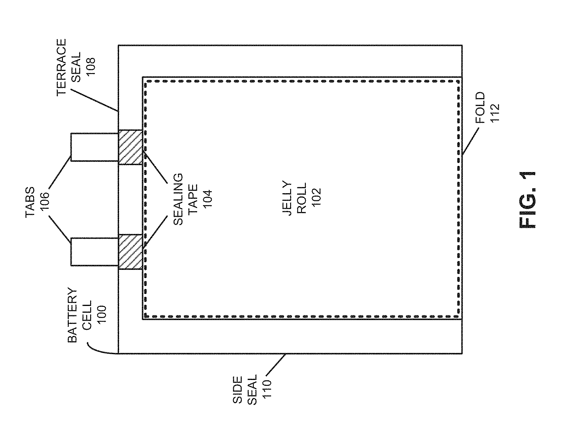
FIG. 1 shows a top-down view of a battery cell in accordance with the disclosed embodiments.
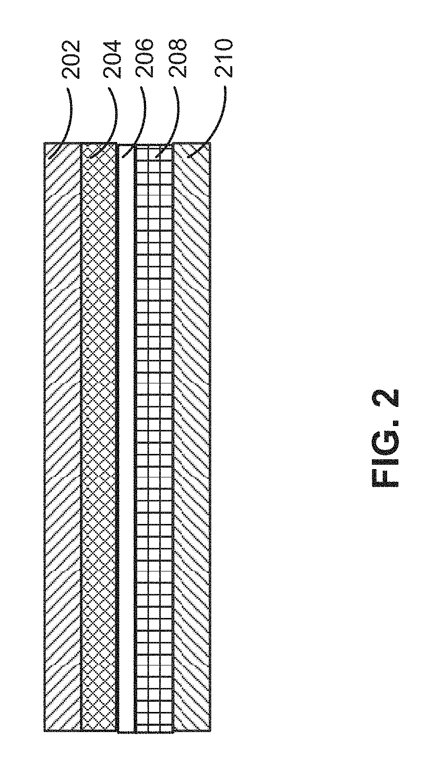
FIG. 2 shows a set of layers for a battery cell in accordance with the disclosed embodiments.
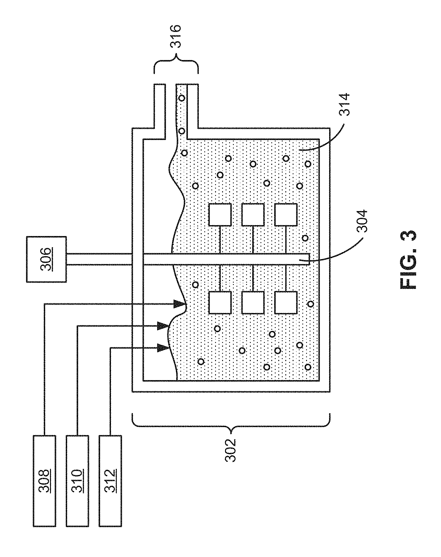
FIG. 3 shows an apparatus for manufacturing a precursor co-precipitate material for a cathode active material composition in accordance with the disclosed embodiments.
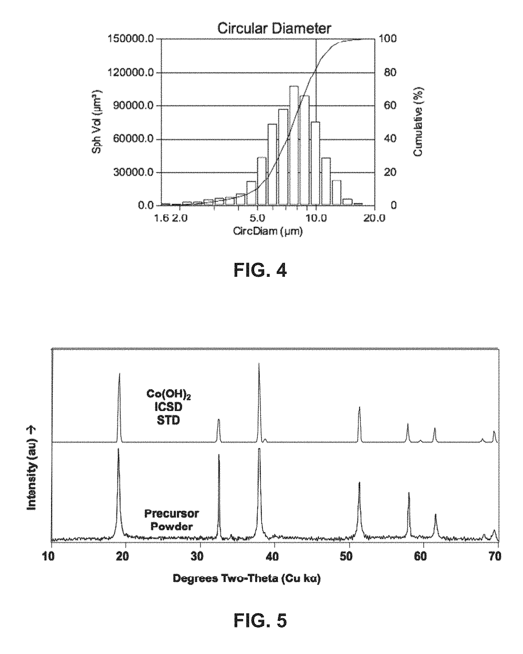
FIG. 4 shows a histogram and a cumulative distribution of the particle sizes of a precursor co-precipitate material for a cathode active material composition in accordance with the disclosed embodiments.
FIG. 5 shows an X-ray powder diffraction (XRD) of a precursor co-precipitate material for a cathode active material composition in accordance with the disclosed embodiments.
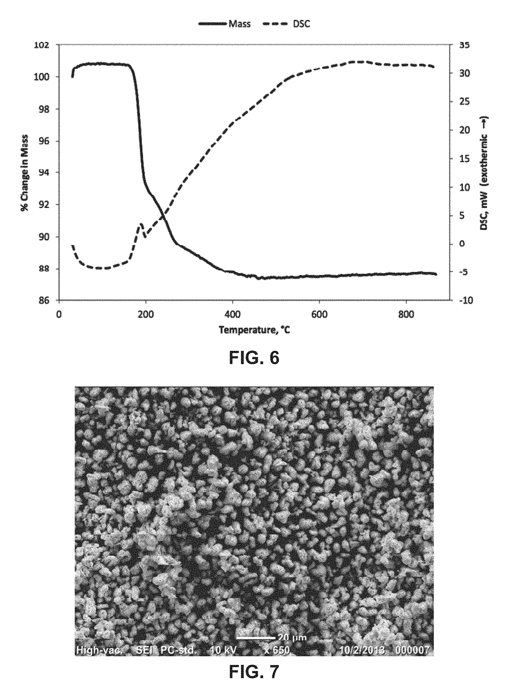
FIG. 6 shows a plot of mass and a differential scanning calorimetry (DSC) curve of a precursor co-precipitate material for a cathode active material composition as a function of temperature in accordance with the disclosed embodiments.
FIG. 7 shows a scanning electron micrograph (SEM) of a precursor co-precipitate material for a cathode active material composition in accordance with the disclosed embodiments.
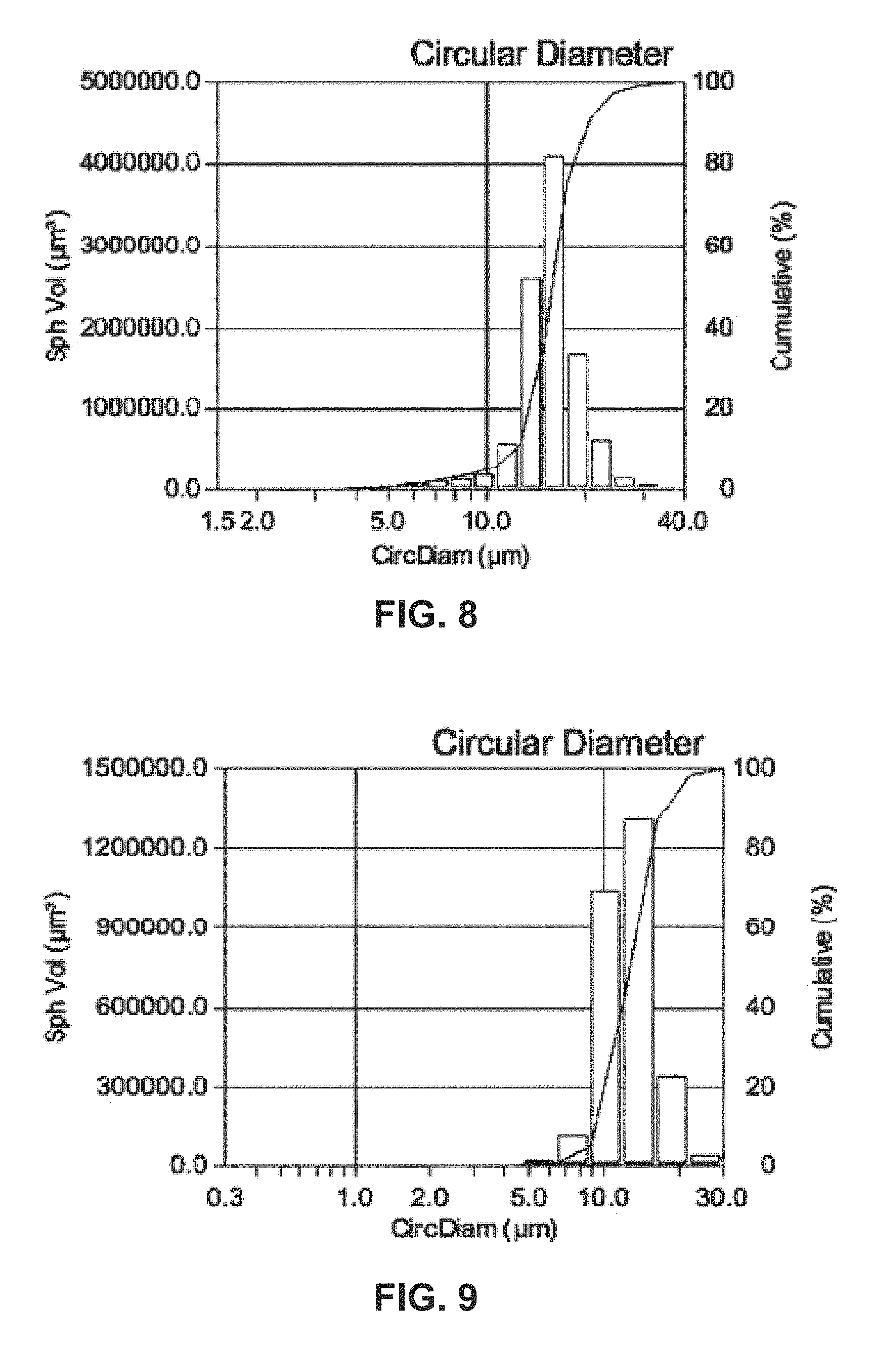
FIG. 8 shows a histogram and a cumulative distribution of the particle sizes of a precursor co-precipitate material for a cathode active material composition in accordance with the disclosed embodiments.
FIG. 9 shows a histogram and a cumulative distribution of the particle sizes of a precursor co-precipitate material for a cathode active material composition in accordance with the disclosed embodiments.
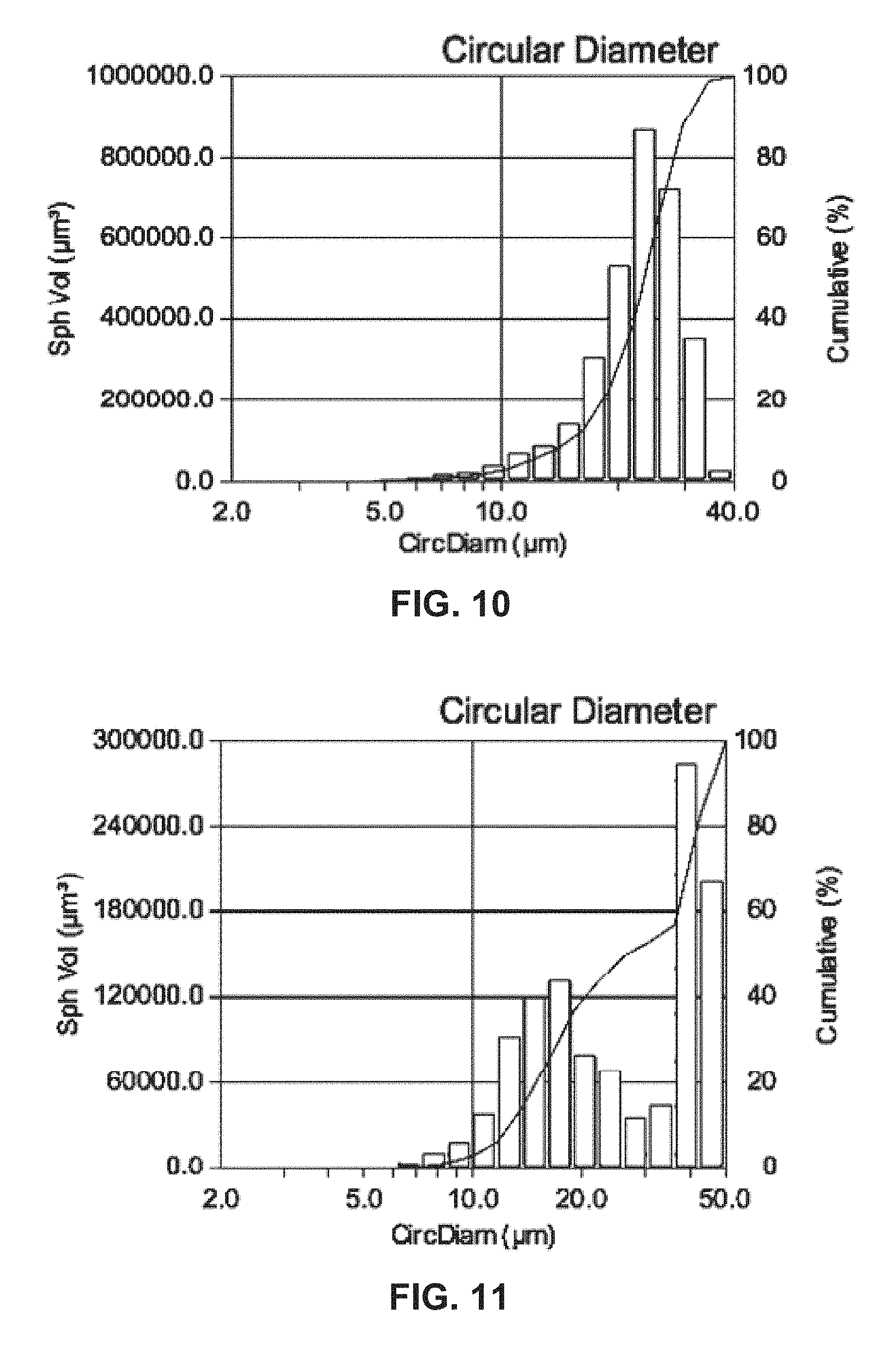
FIG. 10 shows a histogram and a cumulative distribution of the particle sizes of a precursor co-precipitate material for a cathode active material composition in accordance with the disclosed embodiments.
FIG. 11 shows a histogram and a cumulative distribution of the particle sizes of a precursor co-precipitate material for a cathode active material composition in accordance with the disclosed embodiments.
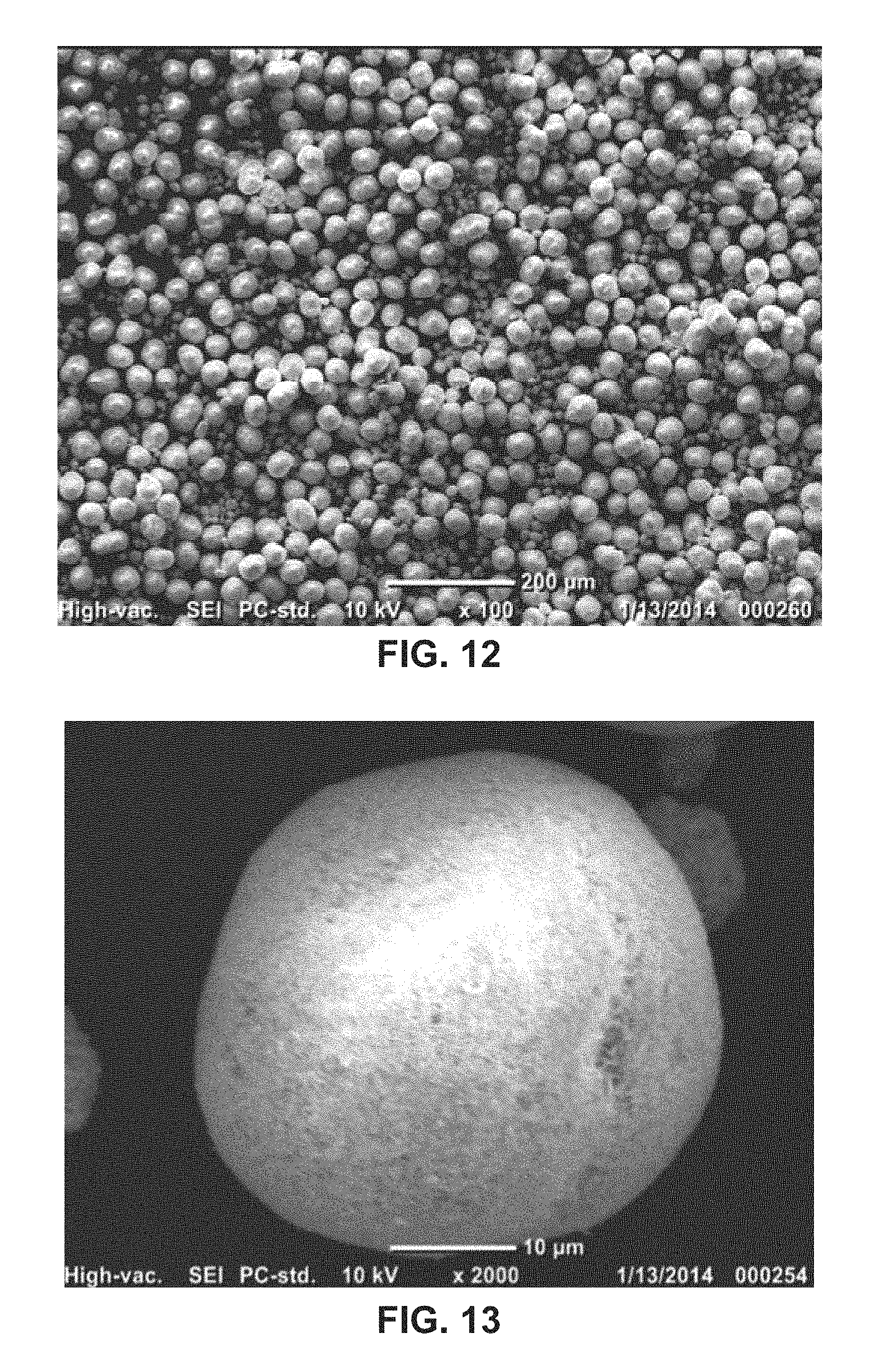
FIG. 12 shows an SEM of a precursor co-precipitate material for a cathode active material composition in accordance with the disclosed embodiments.
FIG. 13 shows an SEM of a precursor co-precipitate material for a cathode active material composition in accordance with the disclosed embodiments.
FIG. 14 shows an SEM of a precursor co-precipitate material for a cathode active material composition in accordance with the disclosed embodiments.
FIG. 15 shows an SEM of a precursor co-precipitate material for a cathode active material composition in accordance with the disclosed embodiments.
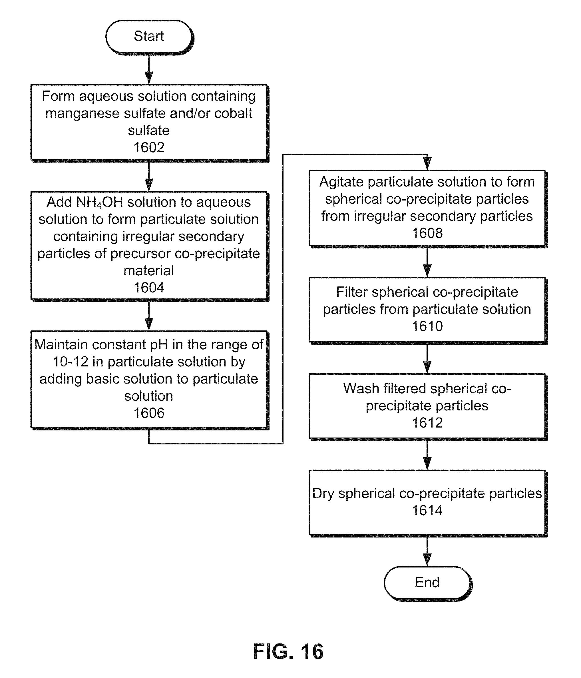
FIG. 16 presents a flow chart illustrating the process of manufacturing a precursor co-precipitate material for a cathode active material composition in accordance with the disclosed embodiments.
FIG. 17 shows a portable electronic device in accordance with the disclosed embodiments.
In the figures, like reference numerals refer to the same figure elements.
DETAILED DESCRIPTION
The following description is presented to enable any person skilled in the art to make and use the embodiments, and is provided in the context of a particular application and its requirements. Various modifications to the disclosed embodiments will be readily apparent to those skilled in the art, and the general principles defined herein may be applied to other embodiments and applications without departing from the spirit and scope of the present disclosure. Thus, the present invention is not limited to the embodiments shown, but is to be accorded the widest scope consistent with the principles and features disclosed herein.
The disclosed embodiments relate to the manufacture of a precursor co-precipitate material for a cathode active material composition. The cathode active material composition may be used in an electrode of a rechargeable battery cell, such as a lithium-ion or lithium-polymer cell.
More specifically, the disclosed embodiments provide a method and apparatus for manufacturing manganese cobalt-rich hydroxide precursors that have unusually large particle size (e.g., 1-40 micron) with uniform narrow distribution, for the subsequent production of cathode active material compositions for secondary lithium-ion batteries. The hydroxide particles may contain Mn and/or Co, and the precursor composition may be represented by Mn.sub.xM.sub.yCo.sub.z(OH).sub.2. M may include one or more metal cations selected preferably from one or more monovalent, divalent, trivalent or tetravalent cations and Ru, examples of which may be Li.sup.+, Ni.sup.2+, Ni.sup.3+, Cu.sup.+, Cu.sup.2+, Mg.sup.2+, Zn.sup.2+, B.sup.3+, Ga.sup.3+, Al.sup.3+, Mn.sup.3+, Mn.sup.4+, Sn.sup.4+, Ti.sup.4+, and/or Ru.sup.4+/5+/6+. If M is a mixture of metal cations, the stoichiometric numbers of the metal cations do not have to be equal. In the precursor composition, x+y+z=1.00, and x may range from 0.01 to less than 1.00 (0.01.ltoreq.x<1.00). y may range from 0 to less than 1.00 (0.ltoreq.y<1.00), and z may range from 0.5 to less than 1.00 (0.50.ltoreq.z<1.00). Preferably, 0.01.ltoreq.x.ltoreq.0.30, 0.ltoreq.y.ltoreq.0.20, and 0.70.ltoreq.z<1.00.
During manufacture of the precursor co-precipitate material, an aqueous solution containing at least one of a manganese sulfate and a cobalt sulfate is formed and fed into a reactor. Next, a NH.sub.4OH solution is added to the aqueous solution to form a particulate solution containing irregular secondary particles of the precursor co-precipitate material. A constant pH in the range of 10-12 is also maintained in the particulate solution by adding a basic solution to the particulate solution.
FIG. 1 shows a top-down view of a battery cell 100 in accordance with an embodiment. Battery cell 100 may correspond to a lithium-ion or lithium-polymer battery cell that is used to power a device used in a consumer, medical, aerospace, defense, and/or transportation application. Battery cell 100 includes a jelly roll 102 containing a number of layers which are wound together, including a cathode with an active coating, a separator, and an anode with an active coating. More specifically, jelly roll 102 may include one strip of cathode material (e.g., aluminum foil coated with a lithium compound) and one strip of anode material (e.g., copper foil coated with carbon) separated by one strip of separator material (e.g., conducting polymer electrolyte). The cathode, anode, and separator layers may then be wound on a mandrel to form a spirally wound structure. Alternatively, the layers may be stacked and/or used to form other types of battery cell structures, such as bi-cell structures. Jelly rolls are well known in the art and will not be described further.
During assembly of battery cell 100, jelly roll 102 is enclosed in a flexible pouch, which is formed by folding a flexible sheet along a fold line 112. For example, the flexible sheet may be made of aluminum with a polymer film, such as polypropylene. After the flexible sheet is folded, the flexible sheet can be sealed, for example by applying heat along a side seal 110 and along a terrace seal 108. The flexible pouch may be less than 120 microns thick to improve the packaging efficiency and/or energy density of battery cell 100.
Jelly roll 102 also includes a set of conductive tabs 106 coupled to the cathode and the anode. Conductive tabs 106 may extend through seals in the pouch (for example, formed using sealing tape 104) to provide terminals for battery cell 100. Conductive tabs 106 may then be used to electrically couple battery cell 100 with one or more other battery cells to form a battery pack. For example, the battery pack may be formed by coupling the battery cells in a series, parallel, or series-and-parallel configuration. The coupled cells may be enclosed in a hard case to complete the battery pack, or the coupled cells may be embedded within the enclosure of a portable electronic device, such as a laptop computer, tablet computer, mobile phone, personal digital assistant (PDA), digital camera, and/or portable media player.
FIG. 2 shows a set of layers for a battery cell (e.g., battery cell 100 of FIG. 1) in accordance with the disclosed embodiments. The layers may include a cathode current collector 202, cathode active coating 204, separator 206, anode active coating 208, and anode current collector 210. Cathode current collector 202 and cathode active coating 204 may form a cathode for the battery cell, and anode current collector 210 and anode active coating 208 may form an anode for the battery cell. The layers may be wound or stacked to create the battery cell.
As mentioned above, cathode current collector 202 may be aluminum foil, cathode active coating 204 may be a lithium compound, anode current collector 210 may be copper foil, anode active coating 208 may be carbon, and separator 206 may include a conducting polymer electrolyte.
For example, cathode active coating 204 may include a cathode active material composition represented by xLi.sub.2MO.sub.3.(1-x)LiCo.sub.yM'.sub.(1-y)O.sub.2. M may be Mn, Ti, Ru, Zr or a mixture thereof, and M', if present, may include one or more metal cations selected preferably from one or more monovalent, divalent, trivalent or tetravalent cations and Ru, examples of which are Li.sup.+, Ni.sup.2+, Ni.sup.3+, Cu.sup.+, Cu.sup.2+, Mg.sup.2+, Zn.sup.2+, B.sup.3+, Ga.sup.3+, Al.sup.3+, Mn.sup.3+, Mn.sup.4+, Sn.sup.4+, Ti.sup.4+, and/or Ru.sup.4+/5+/6+. If M is a mixture of metal cations, the stoichiometric numbers of the metal cations do not have to be equal. If M' is a mixture of metal cations, the stoichiometric numbers of the metal cations do not have to be equal as long as their sum total (1-y) ranges from 0 to 0.50 (0.ltoreq.(1-y)<0.50). Those skilled in the art will appreciate that other cathode active material compositions may be used with cathode active coating 204.
Such active material compositions can be used in rechargeable lithium cells and batteries, such as battery cell 100 of FIG. 1 and/or other rechargeable battery cell structures. Unlike conventional active materials, the exemplary cathode active material described above uses Li.sub.2MO.sub.3 to stabilize its structure during repeated lithium intercalation and de-intercalation. The resulting structure contains a Li.sub.2MO.sub.3 domain, which inherently contains the LiM.sub.6 component that stabilizes the entire cathode active material structure during battery charging and discharging. This makes it possible to reversibly extract more lithium ion from the structure.
For example, the disclosed cathode active material composition may provide greater than 60% reversible lithium-ion extraction (reversible capacity of cathode active material >165 mAh/g), and possibly greater than 75% reversible lithium-ion extraction (reversible capacity of cathode active material >200 mAh/g) of the cathode active material's theoretical capacity. Cathode active material compositions represented by xLi.sub.2MO.sub.3.(1-x)LiCo.sub.yM'.sub.(1-y)O.sub.2 are discussed further in a co-pending non-provisional application by inventors Hongli Dai, Christopher S. Johnson and Huiming Wu, entitled "High Voltage, High Volumetric Energy Density Li-Ion Battery Using Advanced Cathode Materials," having Ser. No. 14/206,654, and filing date 12 Mar. 2014, which is incorporated herein by reference.
In the disclosed embodiments, the cathode active material composition for cathode active coating 204 (e.g., the Li.sub.2MO.sub.3-stabilized lithium transition metal oxide and/or other cathode active material composition) is preferably synthesized from a mixed-metal hydrated hydroxide precursor previously made by a solution co-precipitation method. This method provides for the best homogeneous mix of transition metals in the intercalation host.
In one or more embodiments, the mixed-metal hydrated hydroxide precursor includes a nickel manganese cobalt-rich hydroxide precursor with an unusually large particle size (e.g., 10-40 micron) and uniform narrow distribution, for the subsequent production of cathode active material compositions for secondary lithium-ion batteries. The hydroxide particles may contain Mn and/or Co, and the precursor composition may be represented by Mn.sub.xM.sub.yCo.sub.z(OH).sub.2. M may include one or more metal cations selected preferably from one or more monovalent, divalent, trivalent or tetravalent cations and Ru, examples of which are Li.sup.+, Ni.sup.2+, Ni.sup.3+, Cu.sup.+, Cu.sup.2+, Mg.sup.2+, Zn.sup.2+, B.sup.3+, Ga.sup.3+, Al.sup.3+, Mn.sup.3+, Mn.sup.4+, Sn.sup.4+, Ti.sup.4+, and/or Ru.sup.4+/5+/6+. If M is a mixture of metal cations, the stoichiometric numbers of the metal cations do not have to be equal. In the precursor composition, x+y+z=1.00, and x may range from 0.01 to less than 1.00 (0.01.ltoreq.x<1.00). y may range from 0 to less than 1.00 (0.ltoreq.y<1.00), and z may range from 0.5 to less than 1.00 (0.50.ltoreq.z<1.00). Preferably, 0.01.ltoreq.x.ltoreq.0.30, 0.ltoreq.y.ltoreq.0.20, and 0.70.ltoreq.z<1.00.
As shown in FIG. 3, manganese nickel cobalt hydroxide precursor particles are nucleated and grown in a co-precipitation process where solutions of metal salts and aqueous ammonia are dripped into a reactor 302 such as a continuous stirred-tank reactor (CSTR), preferably at a constant rate. Reactor 302 may be maintained at a constant temperature of 30-65.degree. C., under a controlled atmosphere using flowing nitrogen, argon, and/or other inert gas. A first feeding mechanism 308 may add an aqueous solution containing a manganese sulfate and/or a cobalt sulfate to reactor 302. For example, feeding mechanism 308 may be used to form an aqueous solution of the manganese and/or cobalt sulfates with a concentration ranging from 0.5-5 mol/L in reactor 302.
A second feeding mechanism 310 may add a NH.sub.4OH (e.g., aqueous ammonia) solution as a chelating agent to the aqueous solution to form a particulate solution 314 containing irregular secondary particles of the precursor co-precipitate material. For example, feeding mechanisms 308-310 may be configured to continuously add aqueous solutions of manganese and/or cobalt sulfates and aqueous ammonia, respectively, to reactor 302 to form particulate solution 314. Particulate solution 314 is held to a constant pH, ranging from 10-12, by a pH controller 312 that actuates a pump to inject a basic solution to particulate solution 314. The basic solution may include a dissolved alkali metal (e.g., Li, Na, or K) hydroxide with a concentration ranging from 0.5-10 mol/L, which acts to precipitate the metal ions and provides the counter ion for the precursor solid. Alternatively, an alkali carbonate or oxalate may be substituted for the alkali hydroxide if a carbonate- or oxalate-based precursor is desired.
At the initial stage of the co-precipitation reaction, the irregular secondary particles grow from acicular primary crystals, changing gradually into spherical co-precipitate particles by vigorous stirring by an agitator 304 powered by a motor 306 during a 3-20 hour residence time in reactor 302. Reactor 302 may also contain baffles (not shown) and a draft tube (not shown) to ensure radial mixing and a cyclic vertical flow of particulate solution 314.
When reactor 302 is filled, a uniform mixture of particulate solution 314 is discharged continuously through an overflow tube 316. Spherical co-precipitate particles from the discharged particulate solution 314 are then washed, filtered, and dried. In synthesizing uniform spherical hydroxide particles, the pH, concentration of ammonia, and stirring speed during the co-precipitation reaction are the critical factors in determining the physicochemical properties of the powders. In some cases, surfactant additives are used in the precipitation process.
The following examples describe the principles of the disclosed embodiments as contemplated by the inventors, but they are not to be construed as limiting examples.
Example 1
A 3.5-liter CSTR is filled with distilled water and heated to 55.degree. C. The water is purged with nitrogen while stirring at a rate of 1000 rpm. Then, a 1.5-molar aqueous solution of manganese, nickel, magnesium and cobalt sulfate and a 1-molar solution of aqueous ammonia are continuously dripped into the reactor. The pH is fixed at 10.5 by adding a 3-molar aqueous solution of sodium hydroxide using a pH controller/pump. The particles nucleate and grow in the particulate solution for an 8.5-hour run time. The final precursor particles are washed, filtered and dried. FIGS. 4-7 show the characterization of the precursor powder.
In particular, FIG. 4 shows a histogram and a cumulative distribution of the particle sizes of the resultant precursor co-precipitate material. A particle size analysis of the precursor after 8 hours of growth shows a D50 of 7.7 microns and D10/D90 of 0.45. Moreover, the final precursor particles have a minimum size of 1.60 microns, a maximum size of 16.09 microns, a mean of 7.83 microns, a standard deviation of 2.42 microns, a D10 of 5.01 microns, and a D90 of 10.98 microns. The tap density of the dry powder is measured to be 1.26 g/cm.sup.3.
As shown in FIG. 5, x-ray powder diffraction (XRD) shows a single-phase Co(OH).sub.2 type crystal structure. As shown in FIG. 6, heating the precursor in air shows a multistep exothermic reaction to dehydrate and oxidize the Co(OH).sub.2 particles eventually to Co.sub.3O.sub.4, with an expected 13.6% weight loss. As shown in the scanning electron micrograph (SEM) of FIG. 7, the particles have an equiaxial shape and a uniform size distribution.
Example 2
A co-precipitation reaction is run as in Example 1. The pH is set to 11. The water is purged with nitrogen while stirring at a rate of 1200 rpm. Then, a 2-molar aqueous solution of manganese, nickel and cobalt sulfate and a 1.0-molar solution of aqueous ammonia are continuously dripped into the reactor. The final precursor particles are washed, filtered and dried. The plot of FIG. 8 shows a D50 of 15.67 microns and D10/D90 of 0.59. In addition, the final precursor particles have a minimum size of 1.52 microns, a maximum size of 34.24 microns, a mean of 15.90 microns, a standard deviation of 3.73 microns, a D10 of 12.35 microns, and a D90 of 20.09 microns.
Example 3
A co-precipitation reaction is run as in Example 1. The CSTR is filled with 2 liters of a 0.5-molar Na.sub.2SO.sub.4 salt solution. The water is purged with nitrogen while stirring at a rate of 1100 rpm. Then, a 1.5-molar aqueous solution of manganese, nickel and cobalt sulfate and a 1-molar solution of aqueous ammonia are continuously dripped into the reactor. The pH is set to 10.5. The final precursor particles are washed, filtered and dried. The plot of FIG. 9 shows a D50 of 12.38 microns and D10/D90 of 0.56. The final precursor particles also have a minimum size of 0.35 microns, a maximum size of 28.45 microns, a mean of 12.95 microns, a standard deviation of 3.19 microns, a D10 of 9.67 microns, and a D90 of 17.18 microns. The tap density of the dry powder is measured to be 0.80 g/cm.sup.3.
Example 4
A co-precipitation reaction is run as in Example 1. The reactor is filled with 2 liters of a 1-molar aqueous ammonia solution. The water is purged with nitrogen while stirring at a rate of 1000 rpm. Then, a 2-molar aqueous solution of cobalt sulfate and a 5-molar solution of aqueous ammonia are continuously dripped into the reactor. The pH is set to 10.5. The final precursor particles are washed, filtered and dried. The plot of FIG. 10 shows a D50 of 23.38 microns and D10/D90 of 0.49. The final precursor particles have a minimum size of 2.00 microns, a maximum size of 37.96 microns, a mean of 23.01 microns, a standard deviation of 5.90 microns, a D10 of 14.83 microns, and a D90 of 30.15 microns. The tap density of the dry powder is measured to be 0.86 g/cm.sup.3.
Example 5
2.5 liters of distilled water were introduced into a 4-liter CSTR for a co-precipitation reaction with a rate of 20 ml/min of nitrogen gas protection and agitated at 1200 rpm while maintaining a reactor temperature of 55.degree. C. A 2-molar metal aqueous solution in which nickel sulfate, manganese sulfate, and cobalt sulfate were mixed at a mole ratio of 1:2:97 (target composition Ni.sub.0.01Mn.sub.0.02Co.sub.0.97(OH).sub.2) was continuously added into the reactor at 0.1 liters/hour, and a 5-molar ammonia hydroxide solution was also continuously added into the reactor at 0.46 liters/hour. In addition, the pH is fixed at 10.5 by adding a 10-molar aqueous solution of sodium hydroxide using a pH controller/pump. The average time of retaining the solution in the reactor was maintained at 11 hours by controlling the amount of flow into the reactor. The total run time is about 12 hours. The final precursor particles are washed, filtered and dried.
As shown in the plot of FIG. 11, a particle size analysis of the precursor after 8 hours of growth shows a D50 of 25 microns. The precursor additionally has a minimum size of 2.00 microns, a maximum size of 48.23 microns, a mean of 28.61 microns, a standard deviation of 13.08 microns, a D10 of 12.84 microns, and a D90 of 44.94 microns. The tap density of the dry powder is measured to be 0.96 g/cm.sup.3. From the SEMs of FIGS. 12-13, the particles are uniform spherical shapes, the surfaces of the particles are smooth, and the secondary particles are about 25 microns in diameter.
Metal hydroxide precursors were also prepared using the procedure of Example 5. The compositions of the precursors were set to Co(OH).sub.2, Co.sub.0.96Mn.sub.0.04(OH).sub.2, Co.sub.0.94Ni.sub.0.02Mn.sub.0.04(OH).sub.2, and Co.sub.0.94Mg.sub.0.02Mn.sub.0.04(OH).sub.2.
Example 6
A co-precipitation reaction is run as in Example 5. 2.5 liters of distilled water were introduced into a 4-liter CSTR for a co-precipitation reaction with a rate of 20 ml/min of nitrogen gas protection and agitated at 1200 rpm while maintaining a reactor temperature of 55.degree. C. A 2-molar metal aqueous solution in which nickel sulfate, manganese sulfate, and cobalt sulfate were mixed at a mole ratio of 1:2:97 (target composition Ni.sub.0.01Mn.sub.0.02Co.sub.0.97(OH).sub.2) was continuously added into the reactor at 0.1 liters/hour, and a 5-molar ammonia hydroxide solution was also continuously added into the reactor at 0.1 liters/hour. In addition, the pH is fixed at 11 by adding a 10-molar aqueous solution of sodium hydroxide using a pH controller/pump. The average time of retaining the solution in the reactor was maintained at 11 hours by controlling the amount of flow into the reactor. The total run time is about 24 hours. The final precursor particles are washed, filtered and dried.
From the SEMs of FIGS. 14-15, the particles are spherical shapes, the surfaces of the particles are smooth, and the secondary particles are about 10-40 .mu.m in diameter. The surface area of the precursor is 15.10 m.sup.2/g, and the tap density of the particles is about 1.1 g/cc.
Example 7
A co-precipitation reaction is run as in Example 6. Initially, 2.5 liters of a 0.5-molar sodium sulfate and 1-molar ammonia solution were added into a 4-liter CSTR for a co-precipitation reaction, with a rate of 200 ml/min of nitrogen gas protection and agitated at 1200 rpm, while maintaining a reactor temperature of 55.degree. C. A 2-molar metal aqueous solution in which nickel sulfate, manganese sulfate, and cobalt sulfate were mixed at a mole ratio of 2:2:96 (target composition Ni.sub.0.02Mn.sub.0.02Co.sub.0.96(OH).sub.2) was continuously added into the reactor, and a 5-molar ammonia hydroxide solution was also continuously added into the reactor. In addition, the pH was fixed at 11 by adding a 10-molar aqueous solution of sodium hydroxide using a pH controller/pump. The average time of retaining the solution in the reactor was maintained at 20 hours by controlling the amount of flow into the reactor. The total run time was about 72 hours. The final precursor particles were washed, filtered and dried.
The particles are spherically shaped and smooth. Secondary particles have a D50 of 40 micrometers, with a D10/D90 of 0.7. The tap density of the particles is 1.7 g/cc.
Example 8
2.5 liters of 1-molar aqueous ammonia solution were introduced into a 4-liter CSTR for a co-precipitation reaction with a rate of 20 ml/min of nitrogen gas protection and agitated at 1200 rpm while maintaining a reactor temperature of 55.degree. C. A 1-molar metal aqueous solution in which manganese sulfate, and cobalt sulfate were mixed at a mole ratio of 4:96 (target composition Mn.sub.0.04Co.sub.0.96(OH).sub.2) was continuously added into the reactor at 0.2 liters/hour, and a 5-molar ammonia hydroxide solution was also continuously added into the reactor at 0.05 liters/hour. In addition, the pH is fixed at 11.5 by adding a 10-molar aqueous solution of sodium hydroxide using a pH controller/pump. The average time of retaining the solution in the reactor was maintained at 6.57 hours by controlling the amount of flow into the reactor. The total run time is about 24 hours. The final precursor particles are washed, filtered and dried. The tap density of the dry powder is measured to be 1.78 g/cm.sup.3.
Example 9
A co-precipitation reaction is run as in Example 8. 2.5 liters of 1-molar aqueous ammonia solution were introduced into a 4-liter CSTR for a co-precipitation reaction with a rate of 20 ml/min of nitrogen gas protection and agitated at 1200 rpm while maintaining a reactor temperature of 55.degree. C. A 1-molar metal aqueous solution in which manganese sulfate, cobalt sulfate and magnesium sulfate were mixed at a mole ratio of 4:95.9:0.1 (target composition Mn.sub.0.04Co.sub.0.959Mg.sub.0.001(OH).sub.2) was continuously added into the reactor at 0.2 liters/hour, and a 5-molar ammonia hydroxide solution was also continuously added into the reactor at 0.05 liters/hour. In addition, the pH is fixed at 11.5 by adding a 2-molar aqueous solution of sodium hydroxide using a pH controller/pump. The average time of retaining the solution in the reactor was maintained at 6.57 hours by controlling the amount of flow into the reactor. The total run time is about 24 hours. The final precursor particles are washed, filtered and dried. The tap density of the dry powder is measured to be 1.5 g/cm3.
FIG. 16 presents a flow chart illustrating the process of manufacturing a precursor co-precipitate material for a cathode active material composition in accordance with the disclosed embodiments. In one or more embodiments, one or more of the steps may be omitted, repeated, and/or performed in a different order. Accordingly, the specific arrangement of steps shown in FIG. 16 should not be construed as limiting the scope of the embodiments.
The initial composition of the aqueous solution in the reactor at the beginning of the coprecipitation process contains at least one or a mixture of the following solutions: distilled water, ammonia, sodium sulfate, and/or a mother liquid, which consists of a coprecipitation solution taken from a previous process batch.
An aqueous solution containing a manganese and/or cobalt sulfate is formed (operation 1602). For example, the aqueous solution may be dripped into a CSTR by a feeding mechanism. In addition, a concentration of the nickel, manganese, and cobalt sulfates in the aqueous solution may range from 0.5 mol/L to 5 mol/L.
Next, a NH.sub.4OH solution is added to the aqueous solution to form a particulate solution containing irregular secondary particles of the precursor co-precipitate material (operation 1604). The particulate solution may be maintained at a constant temperature in the range of 30-65.degree. C. and formed in an inert gas atmosphere containing nitrogen, argon, and/or another inert gas. A constant pH in the range of 10-12 is also maintained in the particulate solution by adding a basic solution to the particulate solution (operation 1606). The basic solution may include an alkali metal hydroxide with a concentration in the range of 0.5 mol/L to 10 mol/L, an alkali carbonate, and/or an alkali oxalate.
The particulate solution is further agitated (e.g., in the CSTR) to form spherical co-precipitate particles from the irregular secondary particles (operation 1608). Such agitation may be performed for 3-12 hours to form spherical co-precipitate particles with a median particle size of greater than 15 microns. After the spherical co-precipitate particles have reached their desired size, the spherical co-precipitate particles are filtered from the particulate solution (operation 1610), washed (operation 1612), and dried (operation 1614).
The spherical co-precipitate particles may then be used to form a cathode active material composition for use in a lithium-ion battery. For example, spherical precursor particles formed using the solution co-precipitation reaction described above may have a composition represented by Mn.sub.xM.sub.yCo.sub.z(OH).sub.2, with 0.01.ltoreq.x<1.00, 0.ltoreq.y<1.00, and 0.50.ltoreq.z<1.00. M may include one or more metal cations selected preferably from one or more monovalent, divalent, trivalent or tetravalent cations and Ru, examples of which are Li.sup.+, Ni.sup.2+, Ni.sup.3+, Cu.sup.+, Cu.sup.2+, Mg.sup.2+, Zn.sup.2+, B.sup.3+, Ga.sup.3+, Al.sup.3+, Mn.sup.3+, Mn.sup.4+, Sn.sup.4+, Ti.sup.4+, and/or Ru.sup.4+/5+/6+. If M is a mixture of metal cations, the stoichiometric numbers of the metal cations do not have to be equal. The precursor may be mixed with a lithium salt and heated to 1000.degree. C. in a solid-state reaction to form a cathode active material composition represented by xLi.sub.2MO.sub.3.(1-x)LiCo.sub.2M'.sub.(1-y)O.sub.2. In the cathode active material composition, Ni, Co, M and M' possess an average oxidation state of three. The cathode active material composition may then be used in the cathode active coating of a battery cell to increase the reversible capacity of the battery cell's cathode.
The above-described rechargeable battery cell can generally be used in any type of electronic device. For example, FIG. 17 illustrates a portable electronic device 1700 which includes a processor 1702, a memory 1704 and a display 1708, which are all powered by a battery 1706. Portable electronic device 1700 may correspond to a laptop computer, mobile phone, PDA, tablet computer, portable media player, digital camera, and/or other type of battery-powered electronic device. Battery 1706 may correspond to a battery pack that includes one or more battery cells. Each battery cell may include an anode containing an anode current collector and an anode active material disposed over the anode current collector. The battery cell may also include a cathode containing a cathode current collector and a cathode active material disposed over the cathode current collector. The cathode active material may be formed using spherical precursor co-precipitate particles having a composition represented by Mn.sub.xM.sub.yCo.sub.z(OH).sub.2, with 0.01.ltoreq.x<1.00, 0.ltoreq.y<1.00, and 0.50.ltoreq.z<1.00. The cathode and anode may be sealed in a flexible pouch.
The foregoing descriptions of various embodiments have been presented only for purposes of illustration and description. They are not intended to be exhaustive or to limit the present invention to the forms disclosed. Accordingly, many modifications and variations will be apparent to practitioners skilled in the art. Additionally, the above disclosure is not intended to limit the present invention.
* * * * *
References
D00001
D00002
D00003
D00004
D00005
D00006
D00007
D00008
D00009
D00010
D00011
XML
uspto.report is an independent third-party trademark research tool that is not affiliated, endorsed, or sponsored by the United States Patent and Trademark Office (USPTO) or any other governmental organization. The information provided by uspto.report is based on publicly available data at the time of writing and is intended for informational purposes only.
While we strive to provide accurate and up-to-date information, we do not guarantee the accuracy, completeness, reliability, or suitability of the information displayed on this site. The use of this site is at your own risk. Any reliance you place on such information is therefore strictly at your own risk.
All official trademark data, including owner information, should be verified by visiting the official USPTO website at www.uspto.gov. This site is not intended to replace professional legal advice and should not be used as a substitute for consulting with a legal professional who is knowledgeable about trademark law.