System and method for monitoring electrical power usage in an electrical power infrastructure of a building
Maguire , et al. July 9, 2
U.S. patent number 10,345,423 [Application Number 15/855,856] was granted by the patent office on 2019-07-09 for system and method for monitoring electrical power usage in an electrical power infrastructure of a building. This patent grant is currently assigned to BELKIN INTERNATIONAL INC.. The grantee listed for this patent is Belkin International, Inc.. Invention is credited to Yael Maguire, Shwetak N. Patel, Matthew S. Reynolds, Karthik Yogeeswaran.


| United States Patent | 10,345,423 |
| Maguire , et al. | July 9, 2019 |
System and method for monitoring electrical power usage in an electrical power infrastructure of a building
Abstract
A system for monitoring electrical power usage in an electrical power infrastructure of a building. The system can include: a power consumption measurement device configured to be coupled to a first surface of the circuit breaker box, the circuit breaker box containing at least part of the electrical supply conductors for the electrical power infrastructure, the power consumption measurement device comprising one or more electrical current sensors; a first calibration device configured to be electrically coupled to the electrical power infrastructure, the first calibration device comprising one or more first calibration loads; and a calibration module configured to be performed using one or more processors and further configured to at least partially calibrate the power consumption measurement device using a Kalman filter and data obtained from the one or more electrical current sensors of the power consumption measurement device. The power consumption measurement device is configured to obtain at least part of the data while at least one of the one or more first calibration loads is electrically coupled to the electrical power infrastructure and while the power consumption measurement device is coupled to the first surface of the circuit breaker box. Other embodiments are provided.
| Inventors: | Maguire; Yael (Somerville, MA), Yogeeswaran; Karthik (Santa Monica, CA), Patel; Shwetak N. (Seattle, WA), Reynolds; Matthew S. (Seattle, WA) | ||||||||||
|---|---|---|---|---|---|---|---|---|---|---|---|
| Applicant: |
|
||||||||||
| Assignee: | BELKIN INTERNATIONAL INC.
(Playa Vista, CA) |
||||||||||
| Family ID: | 48279965 | ||||||||||
| Appl. No.: | 15/855,856 | ||||||||||
| Filed: | December 27, 2017 |
Prior Publication Data
| Document Identifier | Publication Date | |
|---|---|---|
| US 20180136305 A1 | May 17, 2018 | |
Related U.S. Patent Documents
| Application Number | Filing Date | Patent Number | Issue Date | ||
|---|---|---|---|---|---|
| 15076492 | Mar 21, 2016 | 9857449 | |||
| 13736778 | Mar 22, 2016 | 9291694 | |||
| 13175770 | Aug 12, 2014 | 8805628 | |||
| 13175774 | Mar 3, 2015 | 8972211 | |||
| 61361296 | Jul 2, 2010 | ||||
| 61380174 | Sep 3, 2010 | ||||
| Current U.S. Class: | 1/1 |
| Current CPC Class: | G01R 35/04 (20130101); G01R 35/005 (20130101); G01R 21/133 (20130101); G01R 15/207 (20130101); G01R 21/06 (20130101); G01R 21/001 (20130101); G01R 22/063 (20130101); G01R 22/06 (20130101) |
| Current International Class: | G01R 35/04 (20060101); G01R 35/00 (20060101); G01R 21/133 (20060101); G01R 15/20 (20060101); G01R 21/00 (20060101); G01R 21/06 (20060101); G01R 22/06 (20060101) |
References Cited [Referenced By]
U.S. Patent Documents
| 3714516 | January 1973 | Howe |
| 4012734 | March 1977 | Jagoda et al. |
| 4612617 | September 1986 | Laplace, Jr. et al. |
| 4638417 | January 1987 | Martin et al. |
| 4706073 | November 1987 | Vila Masot |
| 4716409 | December 1987 | Hart et al. |
| 4804957 | February 1989 | Selph et al. |
| 4858141 | August 1989 | Hart et al. |
| 4891587 | January 1990 | Squire |
| 5177560 | January 1993 | Stimple et al. |
| 5229753 | July 1993 | Berg et al. |
| 5233342 | August 1993 | Yashiro et al. |
| 5268666 | December 1993 | Michel et al. |
| 5276629 | January 1994 | Reynolds |
| 5409037 | April 1995 | Wheeler et al. |
| 5428342 | June 1995 | Enoki et al. |
| 5441070 | August 1995 | Thompson |
| 5467011 | November 1995 | Hunt |
| 5483153 | January 1996 | Leeb et al. |
| 5483838 | January 1996 | Holden |
| 5495168 | February 1996 | de Vries |
| 5534663 | July 1996 | Rivers et al. |
| 5590179 | December 1996 | Shincovich et al. |
| 5600310 | February 1997 | Whipple et al. |
| 5635895 | June 1997 | Murr |
| 5650771 | July 1997 | Lee |
| 5699276 | December 1997 | Roos |
| 5717325 | February 1998 | Leeb et al. |
| 5808846 | September 1998 | Holce et al. |
| 5880677 | March 1999 | Lestician |
| 5898387 | April 1999 | Davis et al. |
| 5929315 | July 1999 | Dunegan |
| 6094043 | July 2000 | Scott et al. |
| 6137283 | October 2000 | Williams et al. |
| 6147484 | November 2000 | Smith |
| 6173613 | January 2001 | Dunegan |
| 6273686 | August 2001 | Kroell et al. |
| 6275168 | August 2001 | Slater et al. |
| 6310470 | October 2001 | Hebing et al. |
| 6320968 | November 2001 | Linder |
| 6330516 | December 2001 | Kammeter |
| 6418083 | July 2002 | Wagstaff et al. |
| 6420969 | July 2002 | Campbell |
| 6614211 | September 2003 | Douglas |
| 6622097 | September 2003 | Hunter |
| 6678209 | January 2004 | Peng et al. |
| 6708126 | March 2004 | Culler et al. |
| 6728646 | April 2004 | Howell et al. |
| 6734806 | May 2004 | Cratsley |
| 6771078 | August 2004 | McCauley et al. |
| 6816078 | November 2004 | Onoda et al. |
| 6839644 | January 2005 | Woods et al. |
| 6853291 | February 2005 | Aisa |
| 6860288 | March 2005 | Uhler |
| 6906617 | June 2005 | Van De Meulen |
| 6910025 | June 2005 | Cao |
| 6949921 | September 2005 | Feight et al. |
| 6993417 | January 2006 | Osann, Jr. |
| 7019666 | March 2006 | Tootoonian Mashhad et al. |
| 7043380 | May 2006 | Rodenberg et al. |
| 7049976 | May 2006 | Hunt et al. |
| 7078996 | July 2006 | Cern et al. |
| 7119533 | October 2006 | Tamura et al. |
| 7133729 | November 2006 | Wang et al. |
| 7134568 | November 2006 | Moriyama et al. |
| 7174260 | February 2007 | Tuff et al. |
| 7183669 | February 2007 | Schripsema et al. |
| 7265531 | September 2007 | Stauth et al. |
| 7276915 | October 2007 | Euler et al. |
| 7298133 | November 2007 | Hastings et al. |
| 7330796 | February 2008 | Addink et al. |
| 7400986 | July 2008 | Latham et al. |
| 7417558 | August 2008 | Lightbody et al. |
| 7460930 | December 2008 | Howell et al. |
| 7493221 | February 2009 | Caggiano et al. |
| 7498935 | March 2009 | Kodama et al. |
| 7508318 | March 2009 | Casella et al. |
| 7511229 | March 2009 | Vlasak et al. |
| 7541941 | June 2009 | Bogolea et al. |
| 7546214 | June 2009 | Rivers, Jr. et al. |
| 7589942 | September 2009 | Kumfer et al. |
| 7612971 | November 2009 | Premerlani et al. |
| 7656649 | February 2010 | Loy et al. |
| 7692555 | April 2010 | Stanley et al. |
| 7693670 | April 2010 | Durling et al. |
| 7702421 | April 2010 | Sullivan et al. |
| 7705484 | April 2010 | Horst |
| 7706928 | April 2010 | Howell et al. |
| 7719257 | May 2010 | Robarge et al. |
| 7728986 | June 2010 | Lasker et al. |
| 7729993 | June 2010 | Baraty |
| 7747357 | June 2010 | Murdoch |
| 7755347 | July 2010 | Cullen et al. |
| 7795877 | September 2010 | Radtke et al. |
| 7804280 | September 2010 | Deaver, Sr. et al. |
| 7855655 | December 2010 | Hunter et al. |
| 7885917 | February 2011 | Kuhns et al. |
| 7889061 | February 2011 | Endo |
| 7912530 | March 2011 | Seki et al. |
| 7982596 | July 2011 | Curt et al. |
| 7996171 | August 2011 | Banhegyesi |
| 8049488 | November 2011 | Dempster et al. |
| 8065099 | November 2011 | Gibala et al. |
| 8078431 | December 2011 | Brown |
| 8093765 | January 2012 | Beard |
| 8094034 | January 2012 | Patel et al. |
| 8140414 | March 2012 | O'Neil et al. |
| 8195423 | June 2012 | Von Zon |
| 8325817 | December 2012 | Iwami et al. |
| 8334784 | December 2012 | Patel et al. |
| 8344724 | January 2013 | Leeb et al. |
| 8378845 | February 2013 | Reymann et al. |
| 8392107 | March 2013 | Patel et al. |
| 8463452 | June 2013 | Masters et al. |
| 8494762 | July 2013 | Patel et al. |
| 8659286 | February 2014 | Reynolds |
| 8664564 | March 2014 | Vogel |
| 8712732 | April 2014 | Patel et al. |
| 8924604 | December 2014 | Yogeeswaran et al. |
| 9766277 | September 2017 | Patel et al. |
| 2001/0003286 | June 2001 | Philippbar et al. |
| 2002/0010690 | January 2002 | Howell et al. |
| 2002/0036492 | March 2002 | Slater et al. |
| 2003/0050737 | March 2003 | Osann et al. |
| 2003/0088374 | May 2003 | Slater et al. |
| 2003/0088527 | May 2003 | Hung et al. |
| 2003/0097348 | May 2003 | Cao |
| 2003/0112370 | June 2003 | Long et al. |
| 2003/0151406 | August 2003 | Wan et al. |
| 2003/0158677 | August 2003 | Swarztrauber et al. |
| 2003/0184280 | October 2003 | Bowman et al. |
| 2003/0193405 | October 2003 | Hunt et al. |
| 2003/0216877 | November 2003 | Culler et al. |
| 2004/0027138 | February 2004 | Pickerd et al. |
| 2004/0128034 | July 2004 | Lenker et al. |
| 2004/0140908 | July 2004 | Gladwin et al. |
| 2004/0196024 | October 2004 | Stauth et al. |
| 2004/0206405 | October 2004 | Smith et al. |
| 2004/0229578 | November 2004 | Lightbody et al. |
| 2004/0251897 | December 2004 | Pedersen |
| 2005/0001486 | January 2005 | Schripsema et al. |
| 2005/0060107 | March 2005 | Rodenberg, III et al. |
| 2005/0067049 | March 2005 | Fima et al. |
| 2006/0009928 | January 2006 | Addink et al. |
| 2006/0049831 | March 2006 | Anwar et al. |
| 2006/0050447 | March 2006 | Pellon et al. |
| 2006/0077046 | April 2006 | Endo |
| 2006/0103549 | May 2006 | Hunt et al. |
| 2006/0195275 | August 2006 | Latham et al. |
| 2006/0220833 | October 2006 | Berkman |
| 2006/0226958 | October 2006 | Baril et al. |
| 2006/0245467 | November 2006 | Casella et al. |
| 2006/0259201 | November 2006 | Brown |
| 2006/0259254 | November 2006 | Swarztrauber et al. |
| 2006/0284613 | December 2006 | Hastings et al. |
| 2007/0014369 | January 2007 | Santhoff et al. |
| 2007/0064377 | March 2007 | DeBoer et al. |
| 2007/0067003 | March 2007 | Sanchez et al. |
| 2007/0085534 | April 2007 | Seki et al. |
| 2007/0114987 | May 2007 | Kagan |
| 2007/0132458 | June 2007 | Allen |
| 2007/0152864 | July 2007 | Pease |
| 2007/0230094 | October 2007 | Carlson |
| 2007/0237441 | October 2007 | Roussell et al. |
| 2008/0030075 | February 2008 | Stanley et al. |
| 2008/0042636 | February 2008 | Koste et al. |
| 2008/0079437 | April 2008 | Robarge et al. |
| 2008/0082276 | April 2008 | Rivers et al. |
| 2008/0086394 | April 2008 | O'Neil et al. |
| 2008/0091345 | April 2008 | Patel |
| 2008/0106241 | May 2008 | Deaver et al. |
| 2008/0148877 | June 2008 | Sim |
| 2008/0167755 | July 2008 | Curt |
| 2008/0172192 | July 2008 | Banhegyesi |
| 2008/0224892 | September 2008 | Bogolea et al. |
| 2008/0234983 | September 2008 | Leigh et al. |
| 2008/0255782 | October 2008 | Bilac et al. |
| 2008/0308254 | December 2008 | Premerlani et al. |
| 2009/0043520 | February 2009 | Pollack et al. |
| 2009/0045804 | February 2009 | Durling |
| 2009/0070058 | March 2009 | Lin |
| 2009/0072985 | March 2009 | Patel et al. |
| 2009/0115620 | May 2009 | Hunter et al. |
| 2009/0224754 | September 2009 | Lamarre et al. |
| 2009/0240449 | September 2009 | Gibala et al. |
| 2009/0312968 | December 2009 | Phillips |
| 2010/0030393 | February 2010 | Masters et al. |
| 2010/0049456 | February 2010 | Dempster et al. |
| 2010/0070214 | March 2010 | Hyde et al. |
| 2010/0070218 | March 2010 | Hyde et al. |
| 2010/0088057 | April 2010 | Kopaczewski et al. |
| 2010/0109842 | May 2010 | Patel et al. |
| 2010/0148579 | June 2010 | Maloney |
| 2010/0188262 | July 2010 | Reymann et al. |
| 2010/0219808 | September 2010 | Steckley et al. |
| 2010/0264731 | October 2010 | Arimilli et al. |
| 2010/0280392 | November 2010 | Liu et al. |
| 2011/0004421 | January 2011 | Rosewell et al. |
| 2011/0037444 | February 2011 | Wildash |
| 2011/0043374 | February 2011 | Bannister |
| 2011/0050218 | March 2011 | Lohss |
| 2011/0074382 | March 2011 | Patel |
| 2011/0098949 | April 2011 | Vennelakanti et al. |
| 2011/0112780 | May 2011 | Moss |
| 2011/0194705 | August 2011 | Gautama |
| 2011/0218746 | September 2011 | Joo |
| 2011/0249181 | October 2011 | Iwami et al. |
| 2012/0001617 | January 2012 | Reynolds |
| 2012/0068692 | March 2012 | Patel et al. |
| 2012/0072143 | March 2012 | Yogeeswaran et al. |
| 2012/0072389 | March 2012 | Aldridge et al. |
| 2012/0092142 | April 2012 | Patel et al. |
| 2012/0215410 | August 2012 | McClure |
| 2012/0293146 | November 2012 | Zhao |
| 2013/0119972 | May 2013 | Maguire et al. |
| 2013/0179124 | July 2013 | Patel et al. |
| 2015/0002137 | January 2015 | Patel et al. |
| 2015/0168464 | June 2015 | Yogeeswaran et al. |
| 2016/0154043 | June 2016 | Patel et al. |
| 2016/0202340 | July 2016 | Maguire et al. |
| 070667 | Apr 2010 | AR | |||
| 2705528 | May 2009 | CA | |||
| 1379860 | Nov 2002 | CN | |||
| 1495432 | May 2004 | CN | |||
| 1509410 | Jun 2004 | CN | |||
| 20121017 | Mar 2009 | CN | |||
| 101523226 | Sep 2009 | CN | |||
| 101535819 | Sep 2009 | CN | |||
| 101562074 | Oct 2009 | CN | |||
| 101632292 | Jan 2010 | CN | |||
| 101680676 | Mar 2010 | CN | |||
| 102007032053 | Jan 2009 | DE | |||
| 200312 | Nov 1986 | EP | |||
| 1136829 | Sep 2001 | EP | |||
| 1444527 | Apr 2004 | EP | |||
| 2171363 | Apr 2010 | EP | |||
| 2174395 | Apr 2010 | EP | |||
| 2188879 | May 2010 | EP | |||
| 2645968 | Oct 1990 | FR | |||
| 2680875 | Mar 1993 | FR | |||
| 2228337 | Aug 1990 | GB | |||
| 2235304 | Feb 1991 | GB | |||
| 2461915 | Jan 2010 | GB | |||
| 2465800 | Feb 2010 | GB | |||
| 2464634 | Apr 2010 | GB | |||
| 2464927 | May 2010 | GB | |||
| 2465367 | May 2010 | GB | |||
| 2001190506 | Jul 1989 | JP | |||
| 02212780 | Aug 1990 | JP | |||
| 04050786 | Feb 1992 | JP | |||
| 2004296663 | Oct 1992 | JP | |||
| 2006062512 | Mar 1994 | JP | |||
| 07012976 | Mar 1995 | JP | |||
| 09130961 | May 1997 | JP | |||
| 2009130961 | May 1997 | JP | |||
| 10282161 | Oct 1998 | JP | |||
| 2000258482 | Sep 2000 | JP | |||
| 2001103622 | Apr 2001 | JP | |||
| 2004132790 | Apr 2004 | JP | |||
| 2004219365 | Aug 2004 | JP | |||
| 2005195427 | Jul 2005 | JP | |||
| 2008122083 | Aug 2006 | JP | |||
| 2007107972 | Apr 2007 | JP | |||
| 2010112936 | May 2010 | JP | |||
| 2010282161 | Dec 2010 | JP | |||
| 1019960024384 | Jul 1996 | KR | |||
| 1019980069423 | Oct 1998 | KR | |||
| 1020040087036 | Oct 2004 | KR | |||
| 20080114143 | Dec 2008 | KR | |||
| 20090057058 | Jun 2009 | KR | |||
| 20090057071 | Jun 2009 | KR | |||
| 2010021458 | Feb 2010 | KR | |||
| 1020100032534 | Mar 2010 | KR | |||
| 20100021604 | Aug 2011 | KR | |||
| 2200364 | Mar 2003 | RU | |||
| 2402023 | Oct 2010 | RU | |||
| 1993004377 | Mar 1993 | WO | |||
| 2001050142 | Jul 2001 | WO | |||
| 200300003029 | Jan 2003 | WO | |||
| 20080042483 | Apr 2008 | WO | |||
| 2008150458 | Dec 2008 | WO | |||
| 20080153576 | Dec 2008 | WO | |||
| 20080153577 | Dec 2008 | WO | |||
| 20090040140 | Apr 2009 | WO | |||
| 20090063397 | May 2009 | WO | |||
| 2009081407 | Jul 2009 | WO | |||
| 2010007369 | Jan 2010 | WO | |||
| 20100062398 | Jun 2010 | WO | |||
| 2011035301 | Mar 2011 | WO | |||
| 2011057049 | May 2011 | WO | |||
| 2011104661 | Sep 2011 | WO | |||
| 2012003426 | Jan 2012 | WO | |||
Other References
|
Hemmings, T., Crabtree, A., Rodden, T., Clarke, K., and Rouncefield, M., "Probing the Probes," Proceedings of the 7th Biennial Participatory Design Conference, Jun. 23-25, 2002, pp. 42-50, Malmo, Sweden. cited by applicant . Hirsch et al., "The ELDer Project: Social, Emotional, and Environmental Factors in the Design of Eldercare Technologies." Conference on Universal Usability 2000: 72-79, 2000. cited by applicant . Ho, B., Kao, H.C., Chen, N., et al. HeatProbe: A Thermal-based Power Meter for Accounting Disaggregated Electricity Usage. In UbiComp 2011, 2011. cited by applicant . HomePlug Powerline Alliance, web.archive.org/web/20060225110208/www.homeplug.org/en/products/index.asp- , 2006, 1 page. cited by applicant . Horst, Gale., "Whirlpool Corporation: Woodridge Energy Study and Monitoring Pilot." 1-99, 2006. cited by applicant . Howell, E.K., "How Switches Produce Electrical Noise," IEEE Transactions on Electromagnetic Compatibility, Aug. 1979, pp. 162-170, vol. EMC-21, No. 3. cited by applicant . Iachello et al., "Privacy and Proportionality: Adapting Legal Evaluation Techniques to Inform Design in Ubiquitous Computing." CHI 2005: 91-100, 2005. cited by applicant . International Search Report and Written Opinion for PCT/US12/57224 dated Mar. 8, 2013. cited by applicant . International Search Report and Written Opinion for PCT/US2011/042877, dated Dec. 27, 2011, ten (10) pages. cited by applicant . International Search Report and Written Opinion for PCT/US2011/042873, dated Dec. 27, 2011, ten (10) pages. cited by applicant . International Search Report and Written Opinion for PCT/US11/033992, dated Dec. 26, 2011. cited by applicant . International Search Report and Written Opinion for PCT/US2011/043410, dated Feb. 28, 2011, ten (10) pages. cited by applicant . Intille, S.S., Tapia, E.M., Rondoni, J., Beaudin, J., Kukla, C., Agarwal, S., Bao, L., and Larson, K., "Tools for Studying Behavior and Technology in Natural Settings," In the Proceedings of UbiComp 2003, 2003. cited by applicant . Kawahara, Y., Hodges, S., Cook, B.S., and Abowd, G.D. Instant Inkjet Circuits: Lab-based Inkjet Printing to Support Rapid Prototyping of UbiComp Devices. In UbiComp 2013, 363-372, 2013. cited by applicant . Kientz et al., "The Georgia Tech Aware Home." CHI 2008: 3675-3680, 2008. cited by applicant . Kim, Y., Schmid, T., Charbiwala, Z.M., and Srivastava, M.B., "ViridiScope: Design and Implementation of a Fine Grained Power Monitoring System for Homes," In the Proceedings of UbiComp, Sep. 30, 2009, 10 pages. cited by applicant . Kleiner, K., "`Smart Homes` Could Track Your Electrical Noise," New Scientist, Sep. 10, 2007, 2 pages. cited by applicant . Koile, K., Tollmar, K., Demirdjian, D., Shrobe, H., and Darrell, T., "Activity Zones for Context-Aware Computing," Proceedings of UbiComp 2003, Oct. 12-15, 2003, pp. 90-106. cited by applicant . Laughman et al., "Power Signature Analysis." IEEE Power and Engineering Magazine: 56-63, 2003. cited by applicant . Lifton, J., Feldmeier, M., Ono, Y., Lewis, C., and Paradiso, J.A., "A Platform for Ubiquitous Sensor Deployment in Occupational and Domestic Environments," In the Proceedings of the 6th International Conference on Information Processing in Sensor Networks, 2007. cited by applicant . Lorek, M.C., Chraim, F., Pister, K.S.J., and Lanzisera, S. COTS-based stick-on electricity meters for building submetering. 2013 Ieee Sensors, (2013), 1-4. cited by applicant . Mainwaring, S.D., and Woodruff, A., "Investigating Mobility, Technology, and Space in Homes, Starting with Great Rooms," In the Proceedings of EPIC 2005, Nov. 14-15, 2005, pp. 188-195. cited by applicant . Marubayashi, G., "Noise Measurements of the Residential Power Line," Proc. of Int'l. Symposium on Power Line communications, 1997, pp. 104-108. cited by applicant . Mitchell, T., "Machine Learning," McGraw Hill, 1997. cited by applicant . Mountain, Dean., "Price Influences Demand." DeGroote School of Business, McMaster University: 16 pp., 2008. cited by applicant . Murata et al., "Estimation of Power Consumption for Household Electric Appliances." Proceedings of the 9th International Conference on Neural Information Processing: 2209-2303, 2002. cited by applicant . Murph, D., "Electrical Noise Could Help Automate Your Home," Engadget, Sep. 12, 2007, 4 pages. cited by applicant . N.a., "The Value of Disaggregated Feedback." 1 pg., Nov. 19, 2013. cited by applicant . N.a., "End-User-Deployable Whole House Contact-Less Power Consumption Sensing." UbiComp 2009: 4 pp., 2009. cited by applicant . N.a., "Summary: The Impact of Real-Time Feedback on Residential Electricity Consumption: The Hydro One Pilot." 4 pp., 2006. cited by applicant . O'Brien, J., Rodden, T., Rouncefield, M., and Hughes, J., "At Home with the Technology: An Ethnographic Study of a Set-Top-Box Trial," ACM Transactions on Computer-Human Interaction, Sep. 1999, pp. 282-308, vol. 6, No. 3. cited by applicant . P3 International, "Kill a Watt.TM., Electricity Usage Monitor", Innovative Electronic Solutions, http://www.p3international.com/products/special/P4400/P4400-CE.html, 2008, 1 page. cited by applicant . Paradiso, J.A., "Some Novel Applications for Wireless Inertial Sensors," Proc. of NSTI-Nanotech 2006, May 2006, pp. 431-434, Boston, MA. cited by applicant . Parker et al., "Contract Report: Pilot Evaluation of Energy Savings from Residential Energy Demand Feedback Devices." Florida Solar Energy Center, A Research Institute of the University of Central Florida: 32 pp., 2008. cited by applicant . Patel, S.N., Gupta, S., and Reynolds, M.S. The design and evaluation of an end-user-deployable, whole house, contactless power consumption sensor. In CHI 2010, 2010. cited by applicant . Patel, S.N., Robertson, T., Kientz, J.A., Reynolds, M.S., and Abowd, G.D., "At the Flick of a Switch: Detecting and Classifying Unique Electrical Events on the Residential Power Line," In the Proceedings of UbiComp 2007, Sep. 16, 2007. cited by applicant . Patel, S.N., Reynolds, M.S., and Abowd, G.D., "Detecting Human Movement by Differential Air Pressure Sensing in HVAC System Ductwork: An Exploration in Infrastructure Mediated Sensing," In the Proceedings of Pervasive 2008, 2008. cited by applicant . Patel, S.N., Troung, K.N., and Abowd, G.D., "PowerLine Positioning: A Practical Sub-Room-Level Indoor Location System for Domestic Use," In the Proceedings of UbiComp 2006, pp. 441-458, Orange County, CA, 2006. cited by applicant . Patel, Shwetak., "Bringing Sensing to the Masses: An Exploration in Infrastructure-Mediated Sensing." Intel Labs: 133 pp., 2008. cited by applicant . Philipose, M., Fishkin, K.P., Perkowtiz, M., Patterson, D.J., Fox, D., Kautz, H., and Hahnel, D., "Inferring Activities from Interactions with Objects," IEEE Pervasive Computing, Oct.-Dec., 2004, pp. 10-17, vol. 3, Issue 4. cited by applicant . Product Data Sheet for UBA2021 630 V driver IC for CFL and TL lamps, NXP Semiconductors, Jul. 25, 2008, 16 pages. cited by applicant . Prudenzi, A., "A Neuron Nets Based Procedure for Identifying Domestic Appliances Pattern-of-Use from Energy Recordings at Meter Panel." IEEE pp. 941-946, 2002. cited by applicant . Ramirez-Munoz et al., "Design and experimental verification of a smart sensor to measure the energy and power aonsumption in a one-phase AC line." Measurement vol. 42: 412-419, Aug. 2008. cited by applicant . Rosenblat, L., "The Basic Power Supply Tutorial: Design Concepts, Block Diagram, Theory of Operation," http://www.smps.us/power-supply.html, Jun. 8, 2010, 3 pages. cited by applicant . Rowan, J., and Mynatt, E.D., "Digital Family Portrait Field Trial: Support for Aging in Place," Proc. of ACM Conference (CHI 2005), Apr., 2005, pp. 521-530. cited by applicant . Rubner, J., "Tech Professor Developing Camera Cloak," Atlanta Business Chronicle, Jun. 15, 2007, 2 pages. cited by applicant . Steven C. Venema in A Kalman Filter Calibration Method for Analog Quadrature Position Encoders, Copyright 1994, 99 pages. cited by applicant . "Study Finds Elder Care a Growing Emotional and Financial Burden for Baby Boomers," New ADT monitoring service or elderly helps ease the stress of long distance care giving, PR Newswire Europe, Mar. 29, 2005, 4 pages. cited by applicant . Stuntebeck et al., "Wideband PowerLine Positioning for Indoor Localization." UbiComp 2008: 94-103, 2008. cited by applicant . Tapia, E., et al., "Activity Recognition in the Home Setting Using Simple and Ubiquitous Sensors," Pervasive computing (Lecture Notes in Computer Science), 2004, pp. 158-175. cited by applicant . Ito, Masahito et al., "A Method of Appliance Detection Based on Features of Power Waveform," Proceedings of the 2004 International Symposium of Applications and the Internet, Tokyo, Japan, Jan. 26-30, 2004. cited by applicant . Tapia et al., "The Design of a Portable Kit of Wireless Sensors for Naturalistic Data Collection." Pervasive 2006 K.P. Fishkin et al. (Eds.): 117-134, 2006. cited by applicant . Ueno et al., "Effectiveness of Displaying Energy Consumption Data in Residential Houses--Analysis on how the Residents Respond." ECEEE 2005 Summer Study--What Works and Who Delivers?: 1289-1299, 2005. cited by applicant . Warner, Hall-Effect Sensors Measure Up, ECN Magazine, http://www.ecnmag.com/print/articles/2009/03/sensor-zone-april-2009, Apr. 2009. cited by applicant . Weka 3--Data Mining with Open Source Machine Learning Software in Java, "Weka 3: Data Mining Software in Java," http://www.cs.waikato.ac.nz/ml/weka/, Mar. 2006, 1 page. cited by applicant . Williams, Michael K."A Discussion of Methods for Measuring Low-Amplitude Jitter," (1995). cited by applicant . Wilson, D., and Atkeson, C., "Simultaneous Tracking and Activity Recognition (STAR) Using Many Anonymous, Binary Sensors," In the Proceedings of Pervasive 2005, pp. 62-79, 2005. cited by applicant . Wood et al., "Energy-use Information Transfer for Intelligent Homes: Enabling Energy Conservation with Central and Local Displays." Energy and Buildings, vol. 39: 495-503, 2007. cited by applicant . Yunhoon Cho, Design and Implementation of Practical Step Detection Algorithm for Wrist Warn Devices, IEEE Sensors Journal, vol. 16, No. 21, Nov. 1, 2016, pp. 7720-7730. cited by applicant . Abowd, G., and Mynatt, E.D., "Charting Past, Present, and Future Research in Ubiquitous Computing," ACM Transactions on Computer-Human Interaction, Mar. 2000, pp. 29-58, vol. 7, No. 1. cited by applicant . Aipperspach, R., Rattenbury, T., Woodruff, A., and Canny, J., "A Quantitative Method for Revealing and Comparing Places in the Home," In the Proceedings of UbiComp 2006, Sep. 2006, pp. 1-18, Orange County, CA. cited by applicant . Aipperspach, R., Woodruff, A., Anderson, K., and Hooker, B., "Maps of Our Lives: Sensing People and Objects Together in the Home," EECS Department, University of California, Berkeley, Nov. 30, 2005, pp. 1-11. cited by applicant . Anant Sahai, Cyclostationary Feature Detection, 2005, DySPAN, pp. 1-69. cited by applicant . Arvola et al., "Billing Feedback as a Means to Encourage Household Electricity Conservation: A Field Experiment in Helsinki." Proceedings of the 1993 Summer Study of the European Council for Energy Efficient Economy: 11-21, 2003. cited by applicant . Beckmann et al., "Some Assembly Required: Supporting End-User Sensor Installation in Domestic Ubiquitous Computing Environments." UbiComp 2004: 107-124, 2004. cited by applicant . Bian, X., Abowd, G.D., and Rehg, J.M., "Using Sound Source Localization to Monitor and Infer Activities in the Home," In the Proceedings of the Third International Conference on Pervasive Computing, May 8-13, 2005. cited by applicant . Bin Fang, "Development of a Wearable Device for Motion Capturing Based on Magnetic and Inertial Measurement Units," vol. 2017, Article ID 7594763, 11 pages, 2017. cited by applicant . Bin, S. and Dowlatabadi, H. Consumer lifestyle approach to US energy use and the related CO2 emissions. Energy Policy 33, 2 (2005), 197-208. cited by applicant . Brandon et al., "Reducing Household Energy Consumption: A Qualitative and Quantitative Field Study." Journal of Environmental Psychology: 75-85, 1999. cited by applicant . Burges, C., "A Tutorial on Support Vector Machines for Pattern Recognition," Journal of Data Mining and Knowledge Discovery, Jun. 1998, pp. 121-167, vol. 2, Kluwer Academic Publishers, Hingham, MA. cited by applicant . Calwell, C. and Reeder, T., "Power Supplies: A Hidden Opportunity for Energy Savings," NRDC, May 22, 2002, 28 pages. cited by applicant . Chen, J., Kam, A.H., Zhang, J., Liu, N., and Shue, L. Bathroom Activity Monitoring Based on Sound. (2005). In Pervasieve 2009, 47-61. cited by applicant . Chetty et al., "Getting to Green: Understanding Resource Consumption in the Home." UbiComp 2008: 242-251, 2008. cited by applicant . Clifford et al., "A Retrofit 60 Hz Current Sensor for Non-Intrusive Power Monitoring at the Circuit Breaker." 8 pp., 2010. cited by applicant . Compliance Certification Services (Shenzhen) Inc., "FCC Class B Compliance Report," prepared for Jet Way Information Co., Ltd., Dec. 29, 2006, 20 pages. cited by applicant . Cooley, J.J., Member, S., and Vickery, D. A Retrofit 60 Hz Current Sensor for Power Monitoring at the Circuit Breaker Panel, 2010. cited by applicant . Crabtree, A., and Rodden, T., "Domestic Routines and Design for the Home," Computer Supported Cooperative Work: The Journal of Collaborative Computing, Kluwer Academic Publishers, 2004, 40 pages, vol. 13 (2). cited by applicant . Crabtree, A., Rodden, T., Hemmings, T., and Benford, S., "Finding a Place for UbiComp in the Home," In the Proceedings of UbiComp 2003, Oct. 12-15, 2003, pp. 208-226, Seattle, Washington. cited by applicant . Darby, Sarah., "Making it Obvious: Designing Feedback into Energy Consumption." Proceedings of the Second International Conference on Energy Efficiency in Household Appliances and Lighting: 11 pp., 2000. cited by applicant . Darby, Sarah., "The Effectiveness of Feedback on Energy Consumption: A Review for DEFRA on the Literature on Metering, Billing and Direct Displays." Environmental Change Institute: 21 pp., 2006. cited by applicant . Definition of "correlation", thefreedictionary.com, http://www.thefreedictionary.com/p/correlation, last accessed (Oct. 30, 2012). cited by applicant . Drenker, S., and Kader, A., "Nonintrusive Monitoring of Electrical Loads," IEEE Computer Applications in Power, Oct. 1999, pp. 47-51, vol. 12, No. 4. cited by applicant . Edwards, W.K. and Grinter, R.E, "At Home with Ubiquitous Computing: Seven Challenges," In the Proceedings of UbiComp 2001, Sep. 30-Oct. 2, 2001, 17 pages. cited by applicant . Elliot, K., Neustaedter, C., and Greenberg, S., "Time, Ownership and Awareness: The Value of Contextual Locations in the Home," In the Proceedings of UbiComp (Proceedings of the 7th International Conference on Ubiquitous Computing, Tokyo, Japan), 2005. cited by applicant . Fault Tolerant Control and Fault Detection and Isolation, DOI 10.1007/978-0-85729-650-4_2, Springer-Verlag London Limited, 2011, pp. 7-27. cited by applicant . Fischer, Corinna., "Feedback on Household Electricity Consumption: A Tool for Saving Energy?" Energy Efficiency: 79-104, 2008. cited by applicant . Fitzpatrick et al., "Technology-Enabled Feedback on Domestic Energy Consumption: Articulating a Set of Design Concerns." PERVASIVEcomputing: 37-44, 2009. cited by applicant . Fogarty, J., Au, C. And Hudson, S., "Sensing from the Basement: A Feasibility Study of Unobtrusive and Low-Cost Home Activity Recognition," In the Proceedings of ACM Symposium on User Interface Software and Technology. cited by applicant . Formisano, Bob, How to Safely Turn Off Power at the Electrical Panel, http://homerepair.about.com/od/electricalrepair/ss/tum_off main_elect_2.htm?p=1, (Picture from 2009), (last accessed Jun. 13, 2013). cited by applicant . Froehlich, J., Findlater, L., and Landay, J. The design of eco-feedback technology. In CHI 2010, 1999-2008. cited by applicant . Froehlich et al., "Sensing Opportunities for Personalized Feedback Technology to Reduce Consumption." UW CSE Technical Report: CSE Sep. 13, 2001: 7 pp., 2009. cited by applicant . Froehlich, Jon., "Sensing and Feedback of Everyday Activities to Promote Environmentally Sustainable Behaviors." Thesis Proposal, Computer Science and Engineering, University of Washington: 35 pp., 2009. cited by applicant . Froehlich, et. al., "Hydro-Sense: Infrastructure-Mediated Single-Point Sensing of Whole-Home Water Activity," In Proc. of UbiComp 2009, Sep.-Oct. 2009, pp. 235-244, Florida. cited by applicant . Gupta, S., Reynolds, M.S., and Patel, S.N. ElectriSense: Single-Point Sensing Using EMI for Electrical Event Detection and Classification in the Home. In Proc. of UbiComp 2010, 2010. cited by applicant . Hart, G., "Nonintrusive Appliance Load Monitoring," In the Proceedings of the IEEE, Dec. 1992, pp. 1870-1891. cited by applicant. |
Primary Examiner: Lau; Tung S
Attorney, Agent or Firm: Bryan Cave Leighton Paisner LLP
Parent Case Text
CROSS-REFERENCE TO RELATED APPLICATIONS
This application is a divisional of U.S. patent application Ser. No. 15/076,492, filed Mar. 21, 2016, which is a divisional of U.S. patent application Ser. No. 13/736,778, filed Jan. 8, 2013, now U.S. Pat. No. 9,291,694, which is a continuation-in-part of U.S. patent application Ser. No. 13/175,770, filed Jul. 1, 2011, now U.S. Pat. No. 8,805,628, which claims the benefit of U.S. Provisional Application No. 61/361,296, filed Jul. 2, 2010, and U.S. Provisional Application No. 61/380,174, filed Sep. 3, 2010. U.S. patent application Ser. No. 13/736,778 also is a continuation-in-part of U.S. patent application Ser. No. 13/175,774, filed Jul. 1, 2011, now U.S. Pat. No. 8,972,211, which claims the benefit of U.S. Provisional Application No. 61/361,296, filed Jul. 2, 2010, and U.S. Provisional Application No. 61/380,174, filed Sep. 3, 2010.
U.S. patent application Ser. Nos. 15/076,492, 13/736,778, 13/175,770, and 13/175,774, and U.S. Provisional Application Nos. 61/361,296 and 61/380,174 are incorporated herein by reference in their entirety.
Claims
What is claimed is:
1. A system for monitoring electrical power usage in an electrical power infrastructure of a building, the building comprising a circuit breaker box and electrical supply conductors of the electrical power infrastructure of the building, the system comprising: a power consumption measurement device configured to be coupled to a first surface of the circuit breaker box overlying at least part of the electrical supply conductors of the electrical power infrastructure, the power consumption measurement device comprising one or more electrical current sensors to sense a time-varying magnetic field produced by the electrical supply conductors; a first calibration device configured to be electrically coupled to the electrical power infrastructure, the first calibration device comprising one or more first calibration loads, the one or more first calibration loads configured to be removably coupled to a first branch of the electrical power infrastructure; and a calibration module configured to be performed using one or more processors and further configured to at least partially calibrate the power consumption measurement device by applying a Kalman filter using current sensor measurements measured by the one or more electrical current sensors of the power consumption measurement device to estimate a mean of the current sensor measurements as power consumption in the electrical power infrastructure changes as a function of the electrical power usage, wherein: the power consumption measurement device is configured to obtain at least part of the current sensor measurements while at least one of the one or more first calibration loads is electrically coupled to the electrical power infrastructure and while the power consumption measurement device is coupled to the first surface of the circuit breaker box.
2. The system of claim 1, wherein: the calibration module is further configured to apply the Kalman filter using the current sensor measurements measured by the one or more electrical current sensors of the power consumption measurement device to determine one or more first calibration coefficients for the power consumption measurement device.
3. The system of claim 2, further comprising: a processing module configured to be performed using the one or more processors and further configured to use the one or more first calibration coefficients and the current sensor measurements measured by the one or more electrical current sensors of the power consumption measurement device to determine an amount of electrical power being used by one or more loads electrically coupled to the electrical power infrastructure.
4. The system of claim 3, wherein: the calibration module is further configured to re-apply the Kalman filter using the current sensor measurements measured by the one or more electrical current sensors of the power consumption measurement device to re-determine one or more first calibration coefficients for the power consumption measurement device at predetermined time intervals.
5. The system of claim 4, further comprising: a computational unit comprising the calibration module, the processing module, and the one or more processors.
6. The system of claim 5, wherein: the processing module is further configured to use the current sensor measurements measured by the one or more electrical current sensors of the power consumption measurement device to at least partially determine an amount of current being used by the electrical power infrastructure.
7. The system of claim 6, further comprising: a voltage measurement module configured to measure a voltage across the electrical power infrastructure.
8. The system of claim 4, further comprising: a voltage measurement module configured to measure a voltage across the electrical power infrastructure.
9. The system of claim 8, further comprising: a computational unit comprising the calibration module, the processing module, the voltage measurement module, and the one or more processors.
10. The system of claim 9, wherein: the processing module is further configured to use the current sensor measurements measured by the one or more electrical current sensors of the power consumption measurement device to at least partially determine an amount of current being used by the electrical power infrastructure.
11. The system of claim 3, wherein: the processing module is further configured to use the current sensor measurements measured by the one or more electrical current sensors of the power consumption measurement device to at least partially determine an amount of current being used by the electrical power infrastructure.
12. The system of claim 11, further comprising: a voltage measurement module configured to measure a voltage across the electrical power infrastructure.
13. The system of claim 11, wherein: the calibration module is further configured to re-apply the Kalman filter using the current sensor measurements measured by the one or more electrical current sensors of the power consumption measurement device to determine one or more first calibration coefficients for the power consumption measurement device at predetermined time intervals.
14. The system of claim 13, further comprising: a voltage measurement module configured to measure a voltage across the electrical power infrastructure.
15. The system of claim 2, further comprising: a processing module configured to be performed using the one or more processors and further configured to use the current sensor measurements measured by the one or more electrical current sensors of the power consumption measurement device to at least partially determine an amount of current being used by the electrical power infrastructure.
16. The system of claim 15, further comprising: a voltage measurement module configured to measure a voltage across the electrical power infrastructure.
17. The system of claim 2, wherein: the calibration module is further configured to re-apply the Kalman filter using the current sensor measurements measured by the one or more electrical current sensors of the power consumption measurement device to determine one or more first calibration coefficients for the power consumption measurement device at predetermined time intervals.
18. The system of claim 17, further comprising: a voltage measurement module configured to measure a voltage across the electrical power infrastructure.
19. The system of claim 1, further comprising: a processing module configured to be performed using the one or more processors and further configured to use the current sensor measurements measured by the one or more electrical current sensors of the power consumption measurement device to at least partially determine an amount of current being used by the electrical power infrastructure.
20. The system of claim 1, further comprising: a voltage measurement module configured to measure a voltage across the electrical power infrastructure.
Description
FIELD OF THE INVENTION
This invention relates generally to apparatuses, devices, systems, and methods for monitoring electrical power, and relates more particularly to such apparatuses, devices, systems, and methods that monitor electrical power in one or more main electrical power conductors at an electrical circuit breaker panel of a structure.
DESCRIPTION OF THE BACKGROUND
A structure (e.g., a home or a commercial building) can have one or more main electrical power conductors that supply the electrical power to electrical devices (i.e., the load) in the structure. Most structures use a split-phase electrical power distribution system with up to three main electrical power conductors. The main electrical power conductors enter the structure through an electrical circuit breaker panel. An electrical circuit breaker panel is the main electrical distribution point for electricity in a structure. Electrical circuit breaker panels also provide protection from over-currents that could cause a fire or damage electrical devices in the structure. Electrical circuit breaker panels can be coupled to and overlay at least part of the three main power conductors.
Different manufacturers of electrical circuit breaker panels, including, for example, Square-D, Eaton, Cutler-Hammer, General Electric, Siemens, and Murray, have chosen different conductor spacing and configurations for their electrical circuit breaker panels. Furthermore, each manufacturer produces many different configurations of electrical circuit breaker panels for indoor installation, outdoor installation, and for different total amperage ratings, of which 100 amperes (A) and 200 A services are the most common.
The different conductor layouts in the many different types of electrical circuit breaker panels result in different magnetic field profiles at the metal surfaces of the electrical circuit breaker panels. Moreover, the layout of the internal conductors (e.g., the main electrical power conductors) is not visible without opening the breaker panel and the manner in which the internal conductor layout translates into a magnetic field profile at the surface of the electrical circuit breaker panel requires a detailed knowledge of electromagnetic theory to interpret and model correctly. It is, therefore, difficult to measure accurately the magnetic field of the one or more main electrical power conductors at a surface of the electrical circuit breaker panel. If the magnetic field of the one or more main electrical power conductors at a surface of the electrical circuit breaker panel could be accurately determined, the electrical current and power being used by the load in the structure could be determined.
Accordingly, a need or potential for benefit exists for an apparatus, system, and/or method that allows a non-electrician to determine accurately the magnetic field and other parameters related to the one or more main electrical power conductors at the surface of the electrical circuit breaker panel.
BRIEF DESCRIPTION OF THE DRAWINGS
To facilitate further description of the embodiments, the following drawings are provided in which:
FIG. 1 illustrates a view of an exemplary electrical power monitoring system coupled to a circuit breaker panel, according to a first embodiment;
FIG. 2 illustrates a block diagram of electrical power monitoring system, according to the first embodiment;
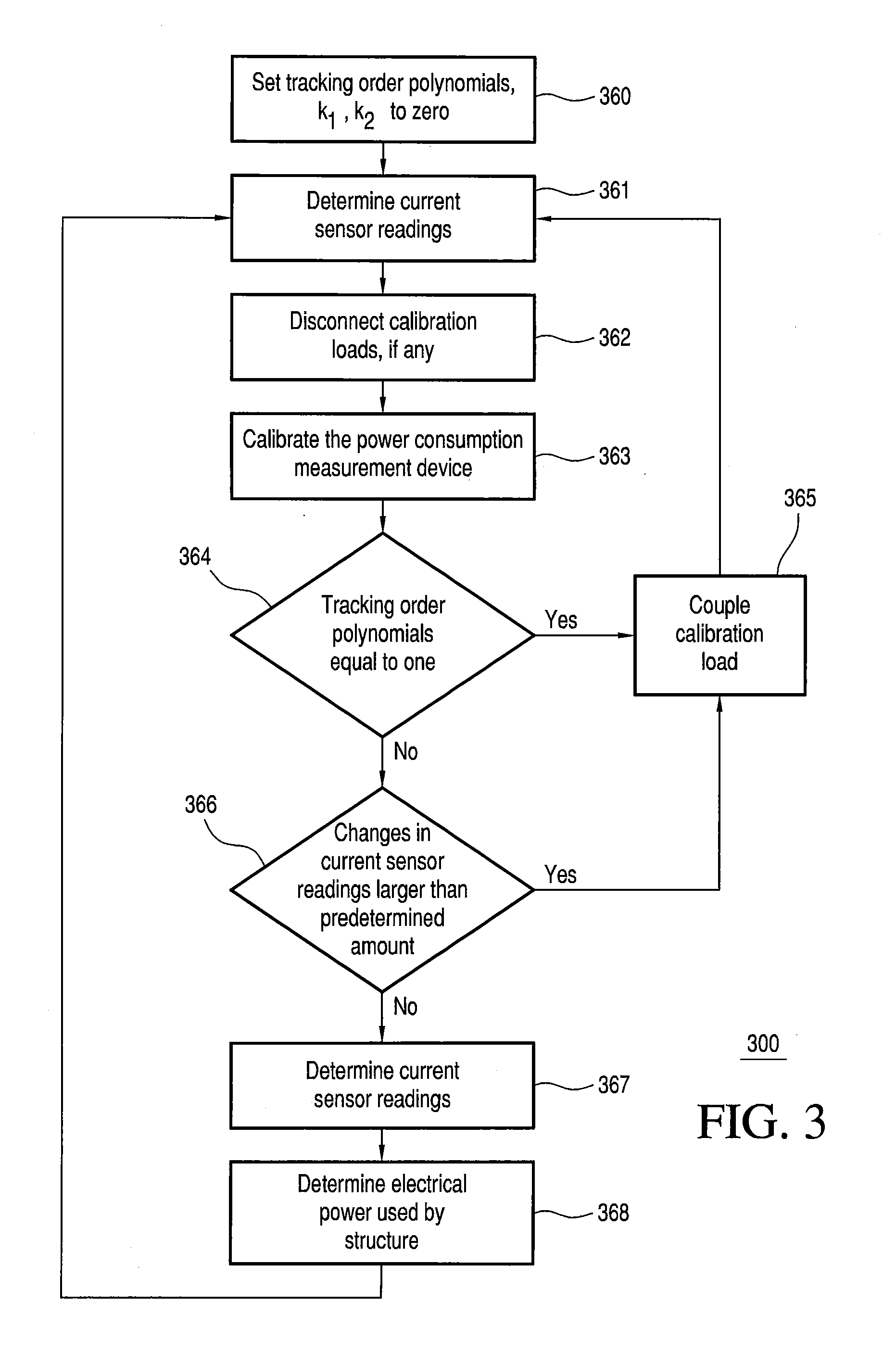
FIG. 3 illustrates an exemplary example of a flow chart for an embodiment of a method of determining the predicted current in the electrical power conductors;
FIG. 4 illustrates an exemplary example of two curves corresponding to the amplitude of two sensors attached to the outer metal plate of an in-home circuit box panel while varying the current through one of the three main power conductors;
FIG. 5 illustrates an exemplary example of sample current waveform over time that corresponds to operating points on curve shown in FIG. 4;
FIG. 6 illustrates shows the amplitude and phase, respectively of a two sensor system as actual data and estimated non-linear parameters over a range of currents for a 2nd order polynomial model;
FIG. 7 shows the error in the current estimate for the 2nd order model of FIG. 6 on the current through conductors;
FIG. 8 illustrates the amplitude and phase of a two sensor system as actual data and estimated non-linear parameters over a range of currents for a 3rd order polynomial model; and
FIG. 9 illustrates the error in the current estimate for the 3rd order model on the current through conductors.
For simplicity and clarity of illustration, the drawing figures illustrate the general manner of construction, and descriptions and details of well-known features and techniques may be omitted to avoid unnecessarily obscuring the invention. Additionally, elements in the drawing figures are not necessarily drawn to scale. For example, the dimensions of some of the elements in the figures may be exaggerated relative to other elements to help improve understanding of embodiments of the present invention. The same reference numerals in different figures denote the same elements.
The terms "first," "second," "third," "fourth," and the like in the description and in the claims, if any, are used for distinguishing between similar elements and not necessarily for describing a particular sequential or chronological order. It is to be understood that the terms so used are interchangeable under appropriate circumstances such that the embodiments described herein are, for example, capable of operation in sequences other than those illustrated or otherwise described herein. Furthermore, the terms "include," and "have," and any variations thereof, are intended to cover a non-exclusive inclusion, such that a process, method, system, article, device, or apparatus that comprises a list of elements is not necessarily limited to those elements, but may include other elements not expressly listed or inherent to such process, method, system, article, device, or apparatus.
The terms "left," "right," "front," "back," "top," "bottom," "over," "under," and the like in the description and in the claims, if any, are used for descriptive purposes and not necessarily for describing permanent relative positions. It is to be understood that the terms so used are interchangeable under appropriate circumstances such that the embodiments of the invention described herein are, for example, capable of operation in other orientations than those illustrated or otherwise described herein.
The terms "couple," "coupled," "couples," "coupling," and the like should be broadly understood and refer to connecting two or more elements or signals, electrically, mechanically and/or otherwise. Two or more electrical elements may be electrically coupled but not be mechanically or otherwise coupled; two or more mechanical elements may be mechanically coupled, but not be electrically or otherwise coupled; two or more electrical elements may be mechanically coupled, but not be electrically or otherwise coupled. Coupling may be for any length of time, e.g., permanent or semi-permanent or only for an instant.
"Electrical coupling" and the like should be broadly understood and include coupling involving any electrical signal, whether a power signal, a data signal, and/or other types or combinations of electrical signals. "Mechanical coupling" and the like should be broadly understood and include mechanical coupling of all types.
The absence of the word "removably," "removable," and the like near the word "coupled," and the like does not mean that the coupling, etc. in question is or is not removable.
DETAILED DESCRIPTION OF EXAMPLES OF EMBODIMENTS
Some embodiments concern a method of using a power consumption measurement device. The power consumption measurement device is mechanically coupled to a surface of a circuit breaker box. The circuit breaker box is overlying at least part of one or more main electrical supply conductors for an electrical power infrastructure of a structure. The method can include: determining at least two first current sensor readings from the one or more main electrical supply conductors using at least one sensor in the power consumption measurement device; calibrating the power consumption measurement device using at least in part the at least two first current sensor readings, wherein calibrating the power consumption measurement device can include: applying a Kalman filter using at least the at least two first current sensor readings to determine one or more first calibration coefficients for the power consumption measurement device; after determining the at least two first current sensor readings, electrically coupling a first calibration load to the electrical power infrastructure; while the first calibration load remains electrically coupled to the electrical power infrastructure, determining at least one second current sensor reading from the one or more main electrical supply conductors using the at least one sensor in the power consumption measurement device; re-calibrating the power consumption measurement device using at least in part the at least two first current sensor readings and the at least one second current sensor reading, wherein re-calibrating the power consumption measurement device can include: applying the Kalman filter using at least the at least two first current sensor readings and the at least one second current sensor reading to determine one or more second calibration coefficients for the power consumption measurement device; uncoupling the first calibration load from the electrical power infrastructure; after uncoupling the first calibration load, determining at least one third current sensor reading from the one or more main electrical supply conductors using the at least one sensor in the power consumption measurement device; and determining a first electrical power used by the electrical power infrastructure of the structure using at least the at least one third current sensor reading and the one or more second calibration coefficients.
The same or different embodiments can concern a method of using an electrical sensor device. The electrical sensor device coupled to a first surface of a circuit breaker box. The circuit breaker box overlying an electrical power infrastructure of a building, the electrical sensor device having two or more electrical current sensors. The method can include: determining a first current measurement of a first current in the electrical power infrastructure and a first phase angle measurement of the first current; determining that a first load is coupled to the electrical power infrastructure; while the first load is coupled to the electrical power infrastructure, determining a second current measurement of a second current in the electrical power infrastructure and a second phase angle measurement of the second current; and using a Kalman filter to determine one or more first calibration coefficients for the electrical sensor device at least in part using the first current measurement, the second current measurement, the first phase angle, and the second phase angle. The first phase angle measurement of the first current is relative to a phase of a first voltage drop across the electrical power infrastructure of the building. The second phase angle measurement of the second current is relative to a phase of a second voltage drop across the electrical power infrastructure of the building.
Some embodiments can concern a system for monitoring electrical power usage in an electrical power infrastructure of a building. The building can comprise a circuit breaker box and electrical supply conductors of the electrical power infrastructure of the building. The system can include: a power consumption measurement device configured to be coupled to a first surface of the circuit breaker box, the circuit breaker box containing at least part of the electrical supply conductors for the electrical power infrastructure, the power consumption measurement device comprising one or more electrical current sensors; a first calibration device configured to be electrically coupled to the electrical power infrastructure, the first calibration device comprising one or more first calibration loads; and a calibration module configured to be performed using one or more processors and further configured to at least partially calibrate the power consumption measurement device using a Kalman filter and data obtained from the one or more electrical current sensors of the power consumption measurement device. The power consumption measurement device is configured to obtain at least part of the data while at least one of the one or more first calibration loads is electrically coupled to the electrical power infrastructure and while the power consumption measurement device is coupled to the first surface of the circuit breaker box.
FIG. 1 illustrates a view of an exemplary electrical power monitoring system 100 coupled to a circuit breaker panel 190, according to a first embodiment. FIG. 2 illustrates a block diagram of electrical power monitoring system 100, according to the first embodiment.
Electrical power monitoring system 100 can also be considered a system for monitoring electrical power usage of a structure (i.e., a building). Electrical power monitoring system 100 can also be considered a devices and system for determining the predicted current used by one or more electrical devices (i.e., the load) in a structure. Electrical power monitoring system 100 is merely exemplary and is not limited to the embodiments presented herein. Electrical power monitoring system 100 can be employed in many different embodiments or examples not specifically depicted or described herein.
In some examples, electrical power monitoring system 100 can include: (a) at least one sensing device 110 (i.e., a power consumption measurement device); (b) at least one computational unit 120; (c) a display device; and (d) at least one calibration device 180.
In some examples, system 100 can be used with breaker panels from different manufacturers and on different types of breaker panels from the same manufacturer. In addition, in some examples, system 100 can be easily installed by an untrained person (i.e., a non-electrician) without opening the breaker panel box and exposing the uninsulated electrical power conductors inside. In some examples sensing device 110 can be located within panel 196 when in operation. In other examples, sensing device 110 can be located outside of panel 196 (e.g., on top of door 197) when in operation.
Also as shown in FIG. 1, a conventional breaker box or circuit breaker panel 190 can include: (a) two or more individual circuit breakers 191; (b) two or main circuit breakers 192; (c) a panel 196 with an exterior surface; and (d) a door 197 that provides access to circuit breakers 191 and 192. At least a portion of main electrical power conductors 193, 194, and 195 can be located within circuit breaker panel 190. "Circuit breaker panel" can also refer to and include fuse boxes, which are still common in buildings with older electrical systems. The electrical power infrastructure of a structure can include at least circuit breaker panel 190 and main electrical power conductors 193, 194, and 195. In some examples, circuit breaker panels can also refer to any type of electrical distribution panel used to provide electricity to a structure.
Main electrical power conductors 193, 194, and 195 are electrically coupled to main circuit breakers 192 and supply the electrical power to electrical devices (i.e., the load) in the structure. Panel 196 overlies at least part of main electrical power conductors 193, 194, and 195 and associated circuitry to protect people from inadvertently contacting these energized electrical power conductors. Usually, panel 196 is composed of steel or another ferrous metal; therefore the magnetic field outside the panel will be non-linearly dependent on the current through power conductors 192, 194, and 195.
Door 197 covers circuit breakers 191 and 192 and is typically closed for aesthetic reasons but can be opened to allow access to the levers of the circuit breakers 191 and 192 within circuit breaker panel 190. In various examples, sensing device 110 can fit within panel 196 so that the door of the breaker panel can be kept closed while sensing device 110 is in operation. In many examples, sensing device 110 has a depth of less than 20 mm. In the same or different examples, sensing device 110 can have a depth of less than 13 mm.
Residential and small commercial electrical service is typically 240 volt split phase service. This refers to the utility providing two 120 V alternating current (AC) source conductors (e.g., power conductors 193 and 194) that are 180 degrees out of phase, along with a neutral conductor (e.g., power conductor 195) that can be used to return current from either power conductor 193 or 194. Power conductors 193, 194, and 195 are the "feeder" or "main" electrical power conductors that carry the incoming power from the utility before being split up into branch circuits that serve different loads. By sensing the magnetic fields generated power conductors 193, 194, and 195, system 100 can sense the total current drawn by all loads from the utility because all loads in the structure are coupled in parallel to power conductors 193, 194, and/or 195.
In the United States, many different types of electrical loads are found in a building served by a 240 V split phase utility service. The electrical loads can be divided into two categories of loads: (a) 120 V loads; and (b) 240 V loads.
The 120 V loads can primarily include lower-wattage loads, i.e., loads plugged into standard 3-prong 120 V 15 A or 120 V 20 A outlets, and small appliances with less than .about.2 kW (kilowatt) power draw. These loads are wired in individual circuits between power conductors 193 and 195 pair (the "first phase branch" or the "193-195 leg" of the wiring circuit) or power conductors 194 and 195 pair (the "second phase branch" or the "194-195 leg" of the wiring circuit). When wiring a structure, electricians attempt to balance the anticipated wattage of loads and outlets on each leg, but this is not an exact process so current in the 193-195 leg and the 194-195 leg are likely to be unbalanced because a different total wattage is typically drawn from each pair. When a 120 V load is turned on, its current flows from the utility, through power conductor 193 or 194 through the main and circuit level circuit breakers, to the load, and then back to power conductor 195 and back to the utility.
The 240 V loads are typically large appliances (e.g., electric dryer, stove, air conditioner compressor, electric baseboard heaters) that consume more than two kW (kilowatts). In this case, the load current flows between power conductors 193 and 194 and no load current flows in power conductor 195. Because of the 180 degree phase relationship between the voltages on power conductors 193 and 194, the total voltage is 240 V.
Referring again to FIGS. 1 and 2, computational unit 120 can include: (a) a communications module 221; (b) a processing module 222; (c) a power source 223 with an electrical connector 128; (d) a user communications device 124; (e) a processor 225; (f) memory 226; (g) a calibration load module 227; (h) a calibration calculation module 229; (i) a control mechanism 132; and (j) electrical voltage sensor 228.
Computational unit 120 can be configured to receive the output signal from calibration device 180 and/or sensing device 110 via communications module 221 and process the output signal to determine one or more parameters related to the electrical power usage of the structure (e.g., the electrical power used by the structure and the electrical current in main electrical power conductors 193, 194, and 195). In some embodiments, computational unit 120 can be a personal computer (PC) or other type of computer (e.g., a tablet).
Processor 225 can be a microcontroller such as the MSP430 microcontroller manufactured by Texas Instruments, Inc. In another embodiment, processor 225 is a digital signal processor such as the TMS320VC5505 digital signal processor manufactured by Texas Instruments, Inc. or a Blackfin digital signal processor manufactured by Analog Devices, Inc.
Processing module 222 can be configured to use current measurements from sensing device 110 to determine one or more parameters related to the electrical power usage of the structure (e.g., the electrical current and electrical power of main electrical power conductors 193, 194, and 195).
As will be explained below, calibration calculation module 229 can be configured to use current measurements from sensing device 110 to calibrate electrical power monitoring system 100 (e.g., calculate the calibration coefficients for sensing device 110). Specifically, calibration calculation module 229 can be configured to at least partially calibrate system 100 using a Kalman filter (described below) and data obtained by sensing device 110. That is, calibration calculation module 229 is configured to apply the Kalman filter using the data obtained from electrical current sensors 211 and 212 to determine one or more calibration coefficients.
In some examples, processing module 222 and calibration calculation module 229 can be stored in memory 226 and configured to run on processor 225. When computational unit 120 is running, program instructions (e.g., processing module 222 and/or calibration calculation module 229) stored in memory 226 are executed by processor 225. A portion of the program instructions, stored in memory 226, can be suitable for carrying out method 300 (FIG. 3) as described below.
Calibration load module 227 can include one or more calibration loads. As will be explained below, the one or more calibration loads can be temporarily electrically coupled to, for example, the first phase branch of the electrical power infrastructure of structure to help calibrate electrical power monitoring system 100.
Electrical voltage sensor 228 can be used to determining the amplitude and phase angle of the voltage across the electrical power infrastructure. The phase angle of the current across is equal to the phase angle measured by electrical current sensors 211 minus the phase angle of the voltage measured using electrical voltage sensor 228. That is, the phase angle of the current can be calculated in reference to the zero point crossing of the voltage.
In some examples, sensing device 110 can communicate the current measurement made by electrical current sensors 211 to computational unit 120 so the phase angle of the current can be calculated. In other examples, computational unit 120 can communicate the voltage measurement by electrical voltage sensor 228 to sensing device 110 so the phase angle of the current can be calculated. In other examples, electrical voltage sensor 228 can be located in calibration device 180.
User communications device 124 can include can include one or more buttons configured to at least partially control computational unit 120. Power source 223 can provide electrical power to communications module 221, a processing module 222, user communications device 124, processor 225, memory 226, and/or electrical voltage sensors 228.
In some examples, power source 223 can be coupled to electrical connector 128 that can be coupled to an electrical wall outlet of the electrical power infrastructure.
In some examples, display device 130 can include: (a) a display 134; (b) a control mechanism 132; (c) an electrical connector 235 configured to coupled to electrical connector 128; and (d) a power source 233. In some examples, display device 134 can be detachable from computational unit 120 and wirelessly communicate with computational unit 120. In other examples display device 120 can be part of computational unit 120.
Power source 223 can provide electrical power to display 134, and control mechanism 132. Display 134 can be configured to display information to a user. In one example, user communications device 134 can be a monitor, a touch screen, and/or one or more LEDs (light emitting diodes).
Control mechanism 132 can include one or more buttons configured to at least partially control computational unit 120 or at least display 134. In one example, control mechanism 132 can include a power switch (i.e., an on/off switch) and/or a display switch configured to control what is displayed on display 134.
Still referring to FIGS. 1 and 2, sensing device 110 can include: (a) two or more or magnetic field sensors or electrical current sensors 211 and 212; (b) a controller 213; (c) a user communications module 214; (d) a communications module 215; (e) a power source 216; and (f) a coupling mechanism 219. Controller 213 can be used to control electrical current sensors 211, user communications module 214, communications module 215, and power source 216.
In some examples, electrical current sensors 211 and 212 can include an inductive pickup, a Hall effect sensor, a magnetoresistive sensor, or any other type of sensor configured to respond to the time varying magnetic field produced by the conductors inside circuit breaker panel 190.
In various examples, sensing device 110 can be configured to be coupled to a surface of panel 196 using coupling mechanism 219. In some examples, coupling mechanism 219 can include an adhesive, a Velcro.RTM. material, a magnet, or another attachment mechanism.
Communications module 215 can be electrically coupled to electrical current sensors 211 and controller 213. In some examples, communications module 215 communicates the voltages or other parameters measured using electrical current sensors 211 to communications module 221 of computational unit 120. In many examples, communications module 215 and communications module 221 can be wireless transceivers. In some examples, electrical signals can be transmitted using Wi-Fi (wireless fidelity), the IEEE (Institute of Electrical and Electronics Engineers) 802.11 wireless protocol or the Bluetooth 4.0+HS (High Speed) wireless protocol. In further examples, these signals can be transmitted via a Zigbee (IEEE 802.15.4 wireless protocol), Z-Wave, or a proprietary wireless standard. In other examples, communications module 215 and communications module 221 can communicate electrical signals using a cellular or wired connection.
User communications module 214 can be configured to display information to a user. In one example, user communications module 214 can be a LCD (liquid crystal display), and/or one or more LEDs (light emitting diodes).
Controller 213 can be configured to control electrical current sensors 211, communications module 215, user communications module 214, and/or power source 216.
Calibration device 180 can include: (a) a communications module 281; (b) an electrical connector 182; (c) a calibration load 283; and (d) a user communication device 184. In some examples, communications module 281 can be similar or the same as communications module 215 and/or 221. Electrical connector 182 can be an electrical power plug in some examples. User communication device 184 can be configured to display information to a user. In one example, user communication device 184 can be one or more LEDs.
FIG. 3 illustrates a flow chart for an embodiment of a method 300 of determining the predicted current in the electrical power conductors. Method 300 is merely exemplary and is not limited to the embodiments presented herein. Method 300 can be employed in many different embodiments or examples not specifically depicted or described herein. In some embodiments, the activities, the procedures, and/or the processes of method 300 can be performed in the order presented. In other embodiments, the activities, the procedures, and/or the processes of the method 300 can be performed in any other suitable order. In still other embodiments, one or more of the activities, the procedures, and/or the processes in method 300 can be combined or skipped.
Method 300 describes a general method of determining the predicted electrical power (and/or electrical current) used in the electrical power conductors of a structure. The method described below can be used to accurately calculate the predicted currents regardless of the position of the sensing device 110 (FIG. 1) on panel 196 (FIG. 1) with the exception of the following points: (a) if electrical current sensors 211 and 212 (FIG. 2) are placed so far away from the main power conductors 193 and 194 (FIG. 1) that almost no discernable signal is measured; and (b) if all of the electrical current sensors 211 and 212 (FIG. 2) are placed very close to neutral electrical power conductor 195 (FIG. 1) and far away from electrical power conductors 193 and 194.
Method 300 (or portions thereof) can also be considered a method of calibrating an electrical monitoring system, according to an embodiment. Method 300 (or portions thereof) can be considered to describe a general method of calibrating a sensing device. This method can involve using a Kalman filter to determine one or more calibration coefficients that can be used to calculate the predicted current in the electrical power infrastructure of the structure.
Referring to FIG. 3, method 300 describes an exemplary method to calibrate the current sensors and determine the electrical current and power in an electrical system of a structure using a Kalman filter.
The Kalman filter, also known as linear quadratic estimation (LQE), is an algorithm which uses a series of measurements observed over time, containing noise (random variations) and other inaccuracies, and produces estimates of unknown variables that tend to be more precise than those that would be based on a single measurement alone. More formally, the Kalman filter operates recursively on streams of noisy input data to produce a statistically optimal estimate of the underlying system state. Specifically, {circumflex over (.chi.)}.sub..kappa./.kappa.-1=A.sub..kappa.{circumflex over (.chi.)}.sub..kappa.-1/.kappa.-1+B.sub..kappa.u.sub..kappa., (1) where {circumflex over (.chi.)}.sub..kappa./.kappa.-1 represents that estimate of x at a time k given observations up to, and including time k-1, A.sub..kappa. is the predict matrix or state transition model that governs the dynamics of the system. B.sub.k is a control matrix with a control vector u.sub..kappa..
The covariance estimate, P.sub.k/k-1, for the state vector is: P.sub..kappa./.kappa.-1=A.sub..kappa.P.sub..kappa.-1/.kappa.-1A.sub..kapp- a..sup.T+Q.sub..kappa.. (2)
Where Q.sub.k is the process noise covariance matrix, from which a process noise is modeled to be added to. With the updated state vector and covariance matrix, Kalman Update steps can be calculated. First, the measurement residual, y.sub..kappa., is calculated: y.sub..kappa.={circumflex over (z)}.sub..kappa.-H.sub..kappa.{circumflex over (.chi.)}.sub..kappa./.kappa.-1, (3) where {circumflex over (z)}.sub..kappa. is the measurement vector and H.sub.k is the observation model. Next, the residual covariance, S.sub.k, is calculated: S.sub..kappa.=H.sub..kappa.P.sub..kappa./.kappa.-1H.sub..kappa..sup.T+R.s- ub..kappa., (4) where R.sub.k is observation noise covariance. Finally, the Kalman gain matrix, K.sub.k, is calculated to update the state vector and covariance matrix: K.sub..kappa.=P.sub..kappa./.kappa.1H.sub..kappa..sup.TS.sub..kappa..sup.- -1 (5) {circumflex over (.chi.)}.sub..kappa./.kappa.={circumflex over (.chi.)}.sub..kappa./.kappa.-1+K.sub..kappa.y.sub..kappa. (6) P.sub..kappa./.kappa.=(I-K.sub..kappa.H.sub..kappa.)P.sub..kappa./.kappa.- -1 (7)
Receiving the amplitude and phase signal from a number of non-contact current sensors, a non-linear model of the system (state vector) can be created: V.sub.t.angle..PHI..sub.t=(A.sub.v1I.sub.1(1+A.sub.t11I.sub.1+ . . . )+A.sub.t10).angle..PHI..sub.1+(B.sub.t1I.sub.2(1+B.sub.t11I.sub.2+ . . . )+B.sub.t10).angle..PHI..sub.2+(C.sub.t1Z(1+C.sub.t11Z.sub.1+ . . . )+C.sub.t10).angle..PHI..sub.3 (8)
For t=1, 2 (2 sensors), and Z=I.sub.1.angle..PHI..sub.1+I.sub.2.angle..PHI..sub.2. These equations can be first, second, third or higher order polynomials, or in principle can be generalized to arbitrary functions (including hyperbolic functions, are used to express relationships in magnetostatics).
For this system, the state vector, X, is estimated to be: {circumflex over (.chi.)}=[L.sub.1.angle.,L.sub.2.angle.,A.sub.t10,A.sub.t1,A.sub.t11- , . . . ,B.sub.t10,B.sub.t1,B.sub.t11, . . . ] (9)
The observation vector, z, is: {circumflex over (z)}=[V.sub.0.angle..PHI..sub.0, . . . ,V.sub.1.angle..PHI..sub.t, . . . ,V.sub.N-1.angle..PHI..sub.N-1] (10) for all the sensors t=(0, . . . , N-1).
To relate the observation vector to the state vector, equation (8) is used. To make the observation model, H.sub..kappa., a Jacobian matrix from equation (8) can be constructed. This makes the update step an Extended Kalman Filter, while the predict step is a normal linear one.
The observation covariance, R.sub..kappa., can be estimated a priori based on the noise of the sensors and system.
Now turning to an application of the Kalman Filter, FIG. 4 illustrates an exemplary example of two curves corresponding to the amplitude of two sensors attached to the outer metal plate of an in-home circuit box panel (e.g., panel 190). As the current is varied on one leg of the electrical power infrastructure from zero Amps to twelve Amps, the corresponding curves are created. Note the curves shown are the case when I.sub.2=0, where I.sub.2 is the current in the second one of conductors 193 and 194.
FIG. 5 illustrates an exemplary example of sample current waveform over time that corresponds to operating points on curve FIG. 4. In some examples, since the calibration procedure is performed at run-time, when system 100 (FIG. 1) cannot control when a user utilizes appliances in the home, any estimation can only be done differentially. For the sake of clarity, system 100 (FIG. 2) is assumed to have a linear model based on the data obtained. In FIG. 5, the first four seconds of operation show a sensor reading on electrical current sensor 211; this corresponds to an input current on conductor 193 of 4 A, created by an appliance in the structure. During this period of time, the change in the current sensor value can be used to continue to estimate the first order curve fit. At the end of period 401 in FIGS. 4 and 5, a linear fit to the data obtained so far has an error relative to the true nonlinear curve 415. In order to correct this error, other parts of the curve must be sampled. After four seconds in the example shown in FIG. 5, an appliance in the environment increases the current by 0.5 A. System 100 (FIG. 1) measures a change in the signal to determine if the change exceeds a predetermined threshold. Once this predetermined threshold is crossed, a fixed current is applied by system 100 (FIG. 1) to move the system to point 5A higher and proceeds along path 410. In some examples, calibration load 283 (FIG. 2) is coupled to the electrical power infrastructure. Given the prediction of what the sensor value should be relative to the known change in load current, a new 2nd order estimate can be created using the Kalman filter. This second order estimate that includes time series data 401, 404, and 410. Based on these additional data points, a new estimated error 416 is substantially less than error 415. As time passes, and more points other than 401 and 410 are sampled, the estimate of the non-linearity in the system 100 will improve, and the estimate of the current in the two legs (e.g., conductors 193 and 194 of FIG. 1) will also improve.
FIG. 6 illustrates shows the amplitude (top) and phase (bottom), respectively of a two sensor system as actual data 602, 605, 612, and 615 (solid lines) and estimated non-linear parameters over a range of L1 current 603, 606, 613, and 616 (dashed lines) for a 2nd order polynomial model. For the sake of clarity, the conductor 194 current is set to 0. FIG. 7 shows the error in the current estimate for the 2nd order model on the current through conductors 193 and 195 both as a percentage error 723, 722 and absolute error 725, 726 in Amps. The error bars are set to a 2% error 724 with a lower bound 727 of 50 mA.
FIG. 8 illustrates the amplitude (top) and phase (bottom) of a two sensor system as actual data 802, 805, 812, and 815 (solid lines) and estimated non-linear parameters over a range of L1 current 803, 806, 813, and 816 (dashed lines) for a 3rd order polynomial model. For the sake of clarity, conductor 194 current is set to 0. FIG. 9 illustrates the error in the current estimate for the 3rd order model on the current through conductors 193 and 195 both as a percentage error 923 and 922, and absolute error 925 and 926 in Amps. The error bars 924 are set to a 2% error with a lower bound 927 of 50 mA. Note that the error for the 2nd and 3rd order polynomials are very similar, suggesting a 2nd order model is sufficient in some embodiments.
Referring back to FIG. 3, method 300 in FIG. 3 includes an activity 360 of setting one or more order tracking polynomials (e.g., k.sub.1 and k.sub.2) to zero. These order tracking polynomials are used in method 300 track the order (first-order, second-order, third-order, etc) of the error of the Kalman filter. In some examples, there is a tracking polynomial for each sensor in the sensing device. For method 300 as described herein, it will be assumed that there are two current sensors in the sensing device. This method can be generalized to a sensing device with any number of current sensors. In this example, the filter order for sensor (e.g., sensors 211 and 212 (FIG. 2)) are set to zero using calibration load module 227 (FIG. 2). Furthermore, the estimation state vector to the filter order of k.sub.1 and k.sub.2 for sensors 1 and 2, respectively are configured. In some examples, the filter order is 0, or simply a constant value for the sensors.
Method 300 next includes an activity 361 of determining at least two first current sensor readings from electrical supply conductors using the current sensors in the power consumption measurement device. In some examples, activity 361 can be considered obtaining and storing one or more first measurements of current.
In some examples, sensing device 110 (FIGS. 1 & 2) can be used to obtain measurements using electrical current sensors 211 and 212 (FIG. 2). These measurements can include the nominal current flowing in at least one of power conductor 193 or 194 (FIG. 1) due to electrical devices that are drawings electrical power. Additionally, at the sensors (e.g., sensors 211 and 212 (FIG. 2)), an amplitude and phase measurement can be made. In some examples, the measurements are made on both the first phase branch and a second phase branch of the electrical power infrastructure.
Method 300 of FIG. 3 continues with an activity 362 of uncoupling any calibration loads coupled to the electrical power infrastructure if a calibration loads is coupled to the electrical power infrastructure. In some examples, the load of calibration device 180 (FIGS. 1 & 2) can be uncoupled from the electrical power infrastructure.
Next, method 300 of FIG. 3 including an activity 363 of calibrating the power consumption measurement device. In some examples, activity 363 uses the current sensor readings from activity 361 to calibrate the power consumption measurement device. As part of activity 363, the filter order for sensor (e.g., sensors 211 and 212 (FIG. 2) can be incremented using calibration load module 227 (FIG. 2).
In many examples, activity 361 can also include applying a Kalman filter using at least the current sensor readings to determine calibration coefficients for the power consumption measurement device. In some examples, calibration load module 227 (FIG. 2) can run on processor 225 (FIG. 2) to calculate the calibration coefficients. That is, calibration load module 227 (FIG. 2) can run a Kalman filter to update the estimate of the calibration polynomial(s). The Kalman filter can estimate the mean of the sensor value(s) as the house power consumption changes as a function of usage. In many examples, the Kalman filter can be calculated as described above.
Method 300 of FIG. 3 continues with an activity 364 of determining if the one or more order tracking polynomials (e.g., k.sub.1 and k.sub.2) are one. If the one or more order taking polynomials are one, the next activity is an activity 365. If the one or more order taking polynomials are not one, the next activity is an activity 366
Activity 365 of method 300 (FIG. 3) include an activity of electrically coupling one or more calibration loads to the electrical power infrastructure. In some examples, calibration load 283 in calibration device 180 (FIG. 2) is coupled to the electrical power infrastructure. After activity 365, the next activity is activity 361 of determining the current sensor readings.
Activity 366 of method 300 of FIG. 3 includes determining if the sensors current readings measured in activity 361 changed by more than a predetermined amount. In one example, the predetermined amount can be 0.5%, 1.0%, 10%, 25%, or 100% of the previous current reading. In other examples, the predetermine amount can be actual current amount (e.g., 0.0.1 A, 0.5 A, 1 A, or 5 A) If the sensor current reading changed by more than the predetermined amount, then the next activity is activity 366. If the sensor current reading did not change by the predetermined amount, the next activity is an activity 367.
In other examples, activity 366 can be skipped if enough calibration reading have been taken in a predetermined period (e.g., a minute, an hour, a day, and a month). Note the threshold can be a dynamic quantity; it is important that the zones where the current is increased with the fixed load are such that they are substantially overlapping, or cover a suitable range of how much the current through each leg could change. Otherwise, the estimator will likely over fit the data, decreasing the accuracy of the estimate.
Activity 367 of determining at least two first current sensor readings from electrical supply conductors using the current sensors in the power consumption measurement device. In some examples, activity 367 can be similar or the same as activity 361 of FIG. 3.
After activity 366, method 300 includes an activity 368 of determining the electrical power usage by the electrical power infrastructure. In some examples, activity 368 can calculate updated calibration coefficients using the Kalman filter and then use the calibration coefficients, the current measurements, the phase angle measurements, and/or voltage measurements to calculate the electrical power and other items related to the electrical energy usage by the structure. After activity 368, the next activity in method 300 is activity 361.
Method 300 establishes simple criteria for enabling the calibration loads to properly calibrate the current sensor. Embodiments of method 300 can allow for more and/or different criteria to be utilized for turning the calibration loads on and for determination of the polynomial order. For example, rather than a threshold in the change of current sensor described in activity 366, the range of anticipated total current coverage, the number of points acquired, random application of the load, or any a priori information concerning the shapes of the curves may be utilized to improve the estimation algorithm and it's convergence properties. Also, the non-linear function may not be a polynomial, but may be a hyperbolic or other type of function.
Although method 300 of FIG. 3 as described uses a Kalman filter, it should be noted that other embodiments of this invention can utilize other filters such as: an Unscented Kalman Filter (UHF); a particle filter; a custom-designed derived Maximum Likelihood or recursive Bayesian estimation algorithm.
Other embodiments of activity 365 of FIG. 3 can include using information from other non-controllable loads in the home instead of or in addition to the calibrations loads 283 (FIG. 2). These additional loads could be used to improve the calibration of system 100 (FIGS. 1 and 2). This method could be used if the controllable loads are small due to cost or size reasons. While it would typically be difficult to identify a specific product within a family of products, if nevertheless one has been identified, recognizing the device turning on and off with known power consumption could be used to perform further calibration of the current sensors. If a large current consumption appliance is recognized, for example a refrigerator or oven, this large current consumption appliance could provide a substantially larger range than the calibration loads, and therefore providing faster convergence or higher accuracy.
Furthermore, the number of coefficients to estimate will affect the minimum number of measurements or sensors required. If the polynomial is of order P, and the 0th order component is non-zero, the number of coefficients to estimate for N sensors will be a total of: 3NP+3N+5 (11) If the 0th order component is zero, this will be 3NP+5. For M measurements, 2NM numbers will be obtained. Assuming the sensors are not linearly dependent, the minimum number of points required to solve for the unknowns will be: 2NM.gtoreq.3NP+3N+5 (12) 2NM.gtoreq.3NP+5 (13)
For the non-zero 0th order and the zero 0th order respectively. As an example, for a 1st order system (P=1) with a zero 0th order component, 2 sensors (N=2), M.gtoreq.3; for a 2nd order system (P=2), M.gtoreq.5; for a 3rd order system (P=3), M.gtoreq.6.
As the polynomial order may increase with increasing number of samples, the order of the state vector or the process covariance, Q.sub..kappa., can be dynamically adjusted to account for changes in the number of samples or confidence in the estimate of the currents from the sensor readings.
Although the invention has been described with reference to specific embodiments, it will be understood by those skilled in the art that various changes may be made without departing from the spirit or scope of the invention. Accordingly, the disclosure of embodiments of the invention is intended to be illustrative of the scope of the invention and is not intended to be limiting. It is intended that the scope of the invention shall be limited only to the extent required by the appended claims. For example, to one of ordinary skill in the art, it will be readily apparent that the method described above in relation to FIG. 3 may be comprised of many different activities, procedures and be performed by many different modules, in many different orders, that any element of figure one may be modified, and that the foregoing discussion of certain of these embodiments does not necessarily represent a complete description of all possible embodiments.
All elements claimed in any particular claim are essential to the embodiment claimed in that particular claim. Consequently, replacement of one or more claimed elements constitutes reconstruction and not repair. Additionally, benefits, other advantages, and solutions to problems have been described with regard to specific embodiments. The benefits, advantages, solutions to problems, and any element or elements that may cause any benefit, advantage, or solution to occur or become more pronounced, however, are not to be construed as critical, required, or essential features or elements of any or all of the claims, unless such benefits, advantages, solutions, or elements are stated in such claim.
Moreover, embodiments and limitations disclosed herein are not dedicated to the public under the doctrine of dedication if the embodiments and/or limitations: (1) are not expressly claimed in the claims; and (2) are or are potentially equivalents of express elements and/or limitations in the claims under the doctrine of equivalents.
* * * * *
References
D00000
D00001
D00002
D00003
D00004
D00005
D00006
XML
uspto.report is an independent third-party trademark research tool that is not affiliated, endorsed, or sponsored by the United States Patent and Trademark Office (USPTO) or any other governmental organization. The information provided by uspto.report is based on publicly available data at the time of writing and is intended for informational purposes only.
While we strive to provide accurate and up-to-date information, we do not guarantee the accuracy, completeness, reliability, or suitability of the information displayed on this site. The use of this site is at your own risk. Any reliance you place on such information is therefore strictly at your own risk.
All official trademark data, including owner information, should be verified by visiting the official USPTO website at www.uspto.gov. This site is not intended to replace professional legal advice and should not be used as a substitute for consulting with a legal professional who is knowledgeable about trademark law.