Multi-piece sealing assembly
Billings , et al. July 9, 2
U.S. patent number 10,344,842 [Application Number 15/070,786] was granted by the patent office on 2019-07-09 for multi-piece sealing assembly. This patent grant is currently assigned to GM GLOBAL TECHNOLOGY OPERATIONS LLC. The grantee listed for this patent is GM Global Technology Operations LLC. Invention is credited to Edward J. Billings, John G. Dorrough, Carl Eric Fonville.


| United States Patent | 10,344,842 |
| Billings , et al. | July 9, 2019 |
Multi-piece sealing assembly
Abstract
A multi-piece seal assembly for use in a torque converter of a motor vehicle includes an inner ring, an outer ring, and an elastomer compensation layer disposed between the inner ring and the outer ring. The inner and outer rings are made from a composite wear material. Tabs on the inner and outer ring interlock with matching slots on the elastomer compensation layer.
| Inventors: | Billings; Edward J. (Ann Arbor, MI), Dorrough; John G. (Oak Park, MI), Fonville; Carl Eric (Ann Arbor, MI) | ||||||||||
|---|---|---|---|---|---|---|---|---|---|---|---|
| Applicant: |
|
||||||||||
| Assignee: | GM GLOBAL TECHNOLOGY OPERATIONS
LLC (Detroit, MI) |
||||||||||
| Family ID: | 56937714 | ||||||||||
| Appl. No.: | 15/070,786 | ||||||||||
| Filed: | March 15, 2016 |
Prior Publication Data
| Document Identifier | Publication Date | |
|---|---|---|
| US 20160290509 A1 | Oct 6, 2016 | |
Related U.S. Patent Documents
| Application Number | Filing Date | Patent Number | Issue Date | ||
|---|---|---|---|---|---|
| 62143308 | Apr 6, 2015 | ||||
| Current U.S. Class: | 1/1 |
| Current CPC Class: | F16H 41/24 (20130101); F16J 15/3284 (20130101); F16J 15/441 (20130101) |
| Current International Class: | F16H 41/24 (20060101); F16J 15/44 (20060101); F16J 15/3284 (20160101) |
| Field of Search: | ;277/373,445 |
References Cited [Referenced By]
U.S. Patent Documents
| 2299813 | October 1942 | Franks |
| 3360998 | January 1968 | Griffel |
| 3887198 | June 1975 | McClure et al. |
| 4151999 | May 1979 | Forster et al. |
| 4600201 | July 1986 | Loenne et al. |
| 4890849 | January 1990 | Eason |
| 5104132 | April 1992 | Onoda et al. |
| 5405458 | April 1995 | Yamagata et al. |
| 5492336 | February 1996 | Barna et al. |
| 5558591 | September 1996 | Erickson et al. |
| 5713578 | February 1998 | Terao et al. |
| 5851568 | December 1998 | Huang |
| 6132844 | October 2000 | Altshuler et al. |
| 6152453 | November 2000 | Kashima et al. |
| 6303254 | October 2001 | Yu et al. |
| 6418959 | July 2002 | Kondo |
| 6884827 | April 2005 | Ota et al. |
| 7008695 | March 2006 | Clough |
| 7654536 | February 2010 | Umetsu et al. |
| 8088496 | January 2012 | Kariya et al. |
| 9360115 | June 2016 | Chaplin |
| 2004/0104536 | June 2004 | Gobeli et al. |
| 2004/0251634 | December 2004 | Shimazu et al. |
| 2006/0060424 | March 2006 | Tominaga et al. |
| 2006/0065487 | March 2006 | Tominaga et al. |
| 2006/0179973 | August 2006 | Matsufuji et al. |
| 2010/0225067 | September 2010 | Bailey |
| 102606705 | Jul 2012 | CN | |||
| 102777598 | Nov 2012 | CN | |||
| 2743376 | May 1978 | DE | |||
| 2314604 | Jan 1998 | GB | |||
Assistant Examiner: Nguyen; Dustin T
Parent Case Text
CROSS-REFERENCE TO RELATED APPLICATIONS
This application claims priority to Provisional U.S. Application No. 62/143,308 filed Apr. 6, 2015. The disclosure of the above application is incorporated herein by reference.
Claims
The following is claimed:
1. A seal assembly for use in a torque converter of a motor vehicle, the seal assembly comprising: an inner ring; an outer ring; an elastomer compensation layer disposed between the inner ring and the outer ring, wherein the elastomer compensation layer is substantially cylindrical and includes an inner surface that defines a plurality of inner slots and an outer surface that defines a plurality of outer slots, wherein the inner ring is substantially cylindrical and includes a plurality of outer tabs that are disposed within the plurality of inner slots of the elastomer compensation layer and the outer rind is substantially cylindrical and includes a plurality of inner tabs that are disposed within the plurality of outer slots of the elastomer compensation layer, wherein the elastomer compensation layer includes a second plurality of outer slots and the outer rind includes a second plurality of inner tabs disposed in the second plurality of outer slots, and each of the second plurality of inner tabs are disposed adjacent and spaced apart from each of the plurality of inner tabs, and wherein the plurality of outer tabs of the inner rind are angularly offset from both the plurality of inner tabs and the second plurality of inner tabs such that each of the outer tabs are equidistant from and angularly between pairs of closely adjacent, spaced apart inner tabs.
2. The seal assembly of claim 1 wherein the inner ring is comprised of the same material as the outer ring and wherein the inner ring and the outer ring are comprised of a composite wear material.
3. The seal assembly of claim 1 wherein the inner and outer slots of the elastomer compensation layer are not radially aligned.
4. The seal assembly of claim 1 wherein the inner and outer slots extend axially from a first side of the elastomer compensation layer to a second side of the elastomer compensation layer.
5. The seal assembly of claim 1 wherein the inner tabs extend axially from a first side of the outer ring to a second side of the outer ring.
6. The seal assembly of claim 5 wherein the outer tabs extend axially from a first side of the inner ring to a second side of the inner ring.
7. The seal assembly of claim 1 wherein the elastomer compensation layer is comprised of a rubber or a polyacrylate.
8. The seal assembly of claim 1 wherein the outer ring has a smooth outer surface.
9. A seal assembly for use in a torque converter of a motor vehicle, the seal assembly comprising: an elastomer compensation ring having an inner surface that defines a plurality of inner slots and an outer surface that defines a plurality of outer slots an inner ring disposed within the elastomer compensation ring and having a plurality of outer tabs formed on an outer surface of the inner ring, wherein each of the plurality of outer tabs is disposed in one of the plurality of inner slots of the elastomer compensation ring; and an outer ring disposed around the elastomer compensation ring and having a plurality of inner tabs formed on an inner surface of the outer ring, wherein each of the plurality of inner tabs is disposed in one of the plurality of outer slots of the elastomer compensation ring, and wherein the plurality of inner and outer slots of the elastomer compensation ring are not radially aligned.
10. The seal assembly of claim 9 wherein the inner ring is comprised of the same material as the outer ring, the elastomer compensation ring is comprised of a material different than the inner ring and outer ring, and wherein the inner ring and the outer ring are comprised of a composite wear material.
11. The seal assembly of claim 9 wherein the inner and outer slots extend axially from a first side of the elastomer compensation ring to a second side of the elastomer compensation ring.
12. The seal assembly of claim 9 wherein the inner tabs extend axially from a first side of the outer ring to a second side of the outer ring.
13. The seal assembly of claim 9 wherein the outer tabs extend axially from a first side of the inner ring to a second side of the inner ring.
14. An assembly in a transmission of a motor vehicle, the motor vehicle having an engine, the assembly comprising: a transmission pump connected to the engine; a converter hub connected to the transmission pump; a turbine hydraulically driven by the converter hub; a turbine output shaft connected to the turbine; a stator shaft concentric to the converter hub, the stator shaft having a port and having a groove formed along a circumference of the stator shaft, wherein the groove is disposed radially between the port and the turbine; and a seal assembly disposed in the groove of the stator shaft, the seal assembly having an elastomer compensation ring having an inner surface that defines a plurality of inner slots and an outer surface that defines a plurality of outer slots, an inner ring disposed within the elastomer compensation ring and having a plurality of outer tabs formed on an outer surface of the inner ring, wherein each of the plurality of outer tabs is disposed in one of the plurality of inner slots of the elastomer compensation ring, and an outer ring disposed around the elastomer compensation ring and having a plurality of inner tabs formed on an inner surface of the outer ring, wherein each of the plurality of inner tabs is disposed in one of the plurality of outer slots of the elastomer compensation ring, and wherein the outer ring is in contact with the converter hub and the inner ring is in contact with the stator shaft, and the elastomeric compensation ring is deformed and contacts a pair of side walls of the groove.
Description
FIELD
The invention relates generally to sealing assemblies used in a transmission of a motor vehicle, and more particularly to a multi-piece sealing assembly that prevents fluid drain-down in a torque converter.
BACKGROUND
The statements in this section merely provide background information related to the present disclosure and may or may not constitute prior art.
There are many applications where a seal is required between a rotating component and a stationary component, such as in a torque converter, a transmission or an engine. A ring seal is used to seal the rotating component to the stationary component in order to keep fluids on either side of the ring seal from escaping to the other side. The ring seal typically includes a circular member that fits around the stationary component and an outer surface that engages the surface of the rotating component. One complication of the above described ring seal is that the ring seal usually remains stationary relative to the rotating component while still maintaining an effective seal to the rotating component. In this regard, the typical ring seal must keep friction forces between the ring seal and the rotating component to a minimum while still maintaining enough radial force to keep fluid from moving past the ring seal.
One solution known in the art to keeping these radial friction forces to a minimum is to force the ring seal to move in an axial direction against a tab or groove formed on the stationary component. By using axial forces, radial forces can be kept to a minimum. Axial forces typically originate from a pressure differential of the fluid on each side of the ring seal. As the pressure differential changes from one side of the ring seal to the other, the ring seal is able to move from one position sealed against the stationary component to a second position sealed against the stationary component.
However, in certain applications, such as a torque converter, it may be desirable to maintain the seal even when there is a reduction in pressure to the energized side of the seal in order to keep the torque converter filled with hydraulic fluid and improve drivability. Thus, there is a need in the art for a ring seal assembly that maintains sealing during low pressure conditions in a torque converter that accommodates high speed, high temperature, tolerance stack-ups, and high pressure.
SUMMARY
A multi-piece seal assembly for use in a torque converter of a motor vehicle includes an inner ring, an outer ring, and an elastomer compensation layer disposed between the inner ring and the outer ring. The inner and outer rings are made from a composite wear material. Tabs on the inner and outer ring interlock with matching slots in the elastomer compensation layer.
In one aspect, the inner ring is comprised of the same material as the outer ring and wherein the inner ring and the outer ring are comprised of a composite wear material.
In another aspect, the elastomer compensation layer is substantially cylindrical and includes an inner surface that defines a plurality of inner slots and an outer surface that defines a plurality of outer slots.
In another aspect, the inner ring is substantially cylindrical and includes a plurality of outer tabs that are disposed within the inner slots of the elastomer compensation layer.
In another aspect, the outer ring is substantially cylindrical and includes a plurality of inner tabs that are disposed within the outer slots of the elastomer compensation layer.
In another aspect, the inner and outer slots of the elastomer compensation layer are not radially aligned.
In another aspect, the inner and outer slots extend axially from a first side of the elastomer compensation layer to a second side of the elastomer compensation layer.
In another aspect, the inner tabs extend axially from a first side of the outer ring to a second side of the outer ring.
In another aspect, the outer tabs extend axially from a first side of the inner ring to a second side of the inner ring.
In another aspect, the elastomer compensation layer includes a second plurality of outer slots and the outer ring includes a second plurality of inner tabs disposed in the second plurality of outer slots, and each of the second plurality of inner tabs are disposed adjacent and spaced apart from each of the plurality of inner tabs.
In another aspect, the plurality of outer tabs of the inner ring are angularly offset from both the plurality of inner tabs and the second plurality of inner tabs such that each of the outer tabs are equidistant from and angularly between pairs of closely adjacent, spaced apart inner tabs.
In another aspect, the elastomer compensation layer is comprised of a rubber or a polyacrylate.
In another aspect, the outer ring has a smooth outer surface.
Further aspects, examples, and advantages will become apparent by reference to the following description and appended drawings wherein like reference numbers refer to the same component, element or feature.
DRAWINGS
The drawings described herein are for illustration purposes only and are not intended to limit the scope of the present disclosure in any way.
FIG. 1 is a cross-sectional view of a portion of an exemplary torque converter having a multi-piece seal assembly;
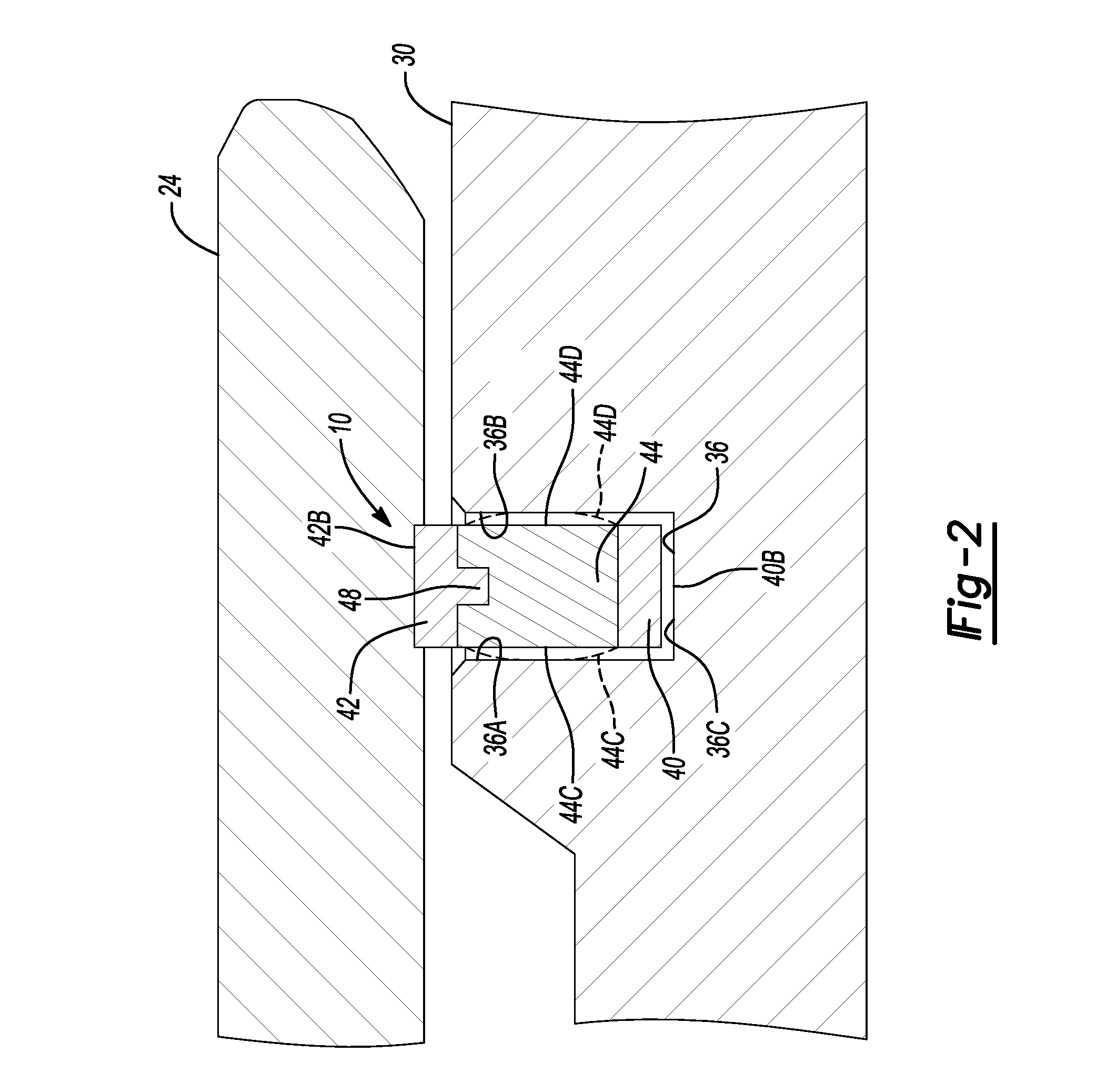
FIG. 2 is an enlarged portion of the torque converter and multi-piece seal assembly indicated by arrows 2-2 in FIG. 1;
FIG. 3 is an isometric, front view of the multi-piece seal assembly;
FIG. 4 is an isometric, exploded front view of the multi-piece seal assembly;
FIG. 5 is an isometric, front view of a second multi-piece seal assembly; and
FIG. 6 is an isometric, exploded front view of the second multi-piece seal assembly.
DETAILED DESCRIPTION
The following description is merely exemplary in nature and is not intended to limit the present disclosure, application, or uses.
With reference to FIG. 1, a multi-piece seal assembly, indicated by reference number 10, is illustrated with an exemplary torque converter 12 in a transmission. A transmission generally includes the torque converter 12, a transmission pump 14, a turbine 16, and a stator 18 contained within a torque converter housing 20. The torque converter housing 20 is coupled to a transmission housing 22. The transmission pump 14 is driven by an engine (not shown) and is connected to a converter hub 24. The converter hub 24 may be connected to and drive a hydraulic pump (not shown). The turbine 16 is connected to a turbine output shaft 26. The turbine output shaft 26 may be connected to and drive a transmission input shaft 28 of a transmission (not shown). The stator 18 is interconnected to a stator shaft 30 of the transmission housing 22 through, for example, a one-way clutch 32. Power is transmitted from the transmission pump 14, driven by the engine, to the turbine 16 through hydraulic fluid. Hydraulic fluid is supplied to the torque converter 12 though a port 34 disposed in the stator shaft 30 of the transmission housing 22.
Turning to FIG. 2 and with continued reference to FIG. 1, the multi-piece seal assembly 10 seals the converter hub 24 to the stator shaft 30 of the transmission housing 22. The converter hub 24 is concentric and rotatable with respect to the stator shaft 30. The multi-piece seal assembly 10 is disposed within a groove 36 formed in the stator shaft 30. The groove 36 extends around the entire periphery or circumference of the stator shaft 30 and is defined by a first wall 36A, a second wall 36B opposite the first wall 36A, and a base 36C extending between the first wall 36A and the second wall 36B. The groove 38 has a width greater than a width of the multi-piece seal assembly 10.
With reference to FIGS. 3 and 4, and with continued reference to FIG. 2, the multi-piece seal assembly 10 includes an inner ring 40, an outer ring 42, and an elastomeric center ring or elastomer compensation layer 44 disposed between the inner ring 40 and the outer ring 42. The inner ring 40 is substantially cylindrical and includes an inner surface 40A and an outer surface 40B. The inner ring 40 includes a plurality of outer tabs 46 formed on the outer surface 40B and disposed symmetrically about the circumference of the inner ring 40. The outer tabs 46 extend along the entire axial length of the inner ring 40. The inner ring 40 is made from a composite wear material, such as ETFE, etc. The composite wear material may include fillers, such as glass filling, to increase strength.
The outer ring 42 is substantially cylindrical and includes an inner surface 42A and an outer surface 42B. The outer ring 42 includes a plurality of inner tabs 48 formed on the inner surface 42A and disposed symmetrically about the inner circumference of the outer ring 42. The inner tabs 48 extend along the entire axial length of the outer ring 42. The outer surface 42B of the outer ring 42 is preferably smooth to facilitate rotation of the converter hub 24 with respect to the multi-piece seal assembly 10. The outer ring 42 is made from a composite wear material, such as ethylene tetrafluoroethylene (ETFE), etc. The thermoplastic polymer may include fillers, such as glass filling, to increase strength.
The center ring 44 is substantially cylindrical and includes an inner surface 44A and an outer surface 44B. The center ring 44 includes a plurality of inner slots 50 formed on the inner surface 44A and disposed symmetrically about the inner circumference of the center ring 44. The inner slots 50 extend axially from a first side 44C of the center ring 44 to a second side 44D of the center ring 44. The inner slots 50 are positioned and sized to receive the outer tabs 46 of the inner ring 40 therein. The center ring 44 also includes a plurality of outer slots 52 formed on the outer surface 44B and disposed symmetrically about the outer circumference of the center ring 44. The outer slots 52 are angularly offset from, or have an angular displacement, with respect to the inner slots 50 and relative to a center point 54 of the multi-piece seal assembly 10. The outer slots 52 extend axially from the first side 44C of the center ring 44 to the second side 44D of the center ring 44. The outer slots 52 are positioned and sized to receive the inner tabs 48 of the outer ring 42 therein. The center ring 44 is made from an elastomer compensation layer such as rubber, polyacrylate, etc.
The multi-piece seal assembly 10 may be made by a combination of insert molding/compression or transfer molding. The molding process combines the individual pieces, i.e. the inner ring 40, outer ring 42, and center ring 44 into a single assembly which will then be installed onto the transmission housing 22. The interlocking of the tabs 46, 48 with the slots 50, 52 rotationally binds the inner, outer, and center rings 40, 42, 44 together. In addition, the surfaces 44A, 44B may be bonded to the respective surfaces 40A, 40B, 42A, 42B of the inner and outer rings 40, 42 to further strengthen the multi-piece seal assembly 10.
When installed, the multi-piece seal assembly 10 is under compressive forces from the converter hub 24 and the stator shaft 30. The elastomer compensation layer 44 thus compresses and the side walls 44C, 44D move axially and seal against the walls 36A, 367B of the groove 36, indicated by dashed lines in FIG. 2. Therefore, even if pressure is reduced on the energized side of the multi-piece seal assembly 10, the multi-piece seal assembly maintains a seal between the converter hub 24 and the stator shaft 30 of the transmission housing 22.
Turning to FIGS. 5 and 6, an alternate multi-piece seal assembly is generally indicated by reference number 10'. The multi-piece seal assembly 10' has certain features in common with the multi-piece seal assembly 10 shown in FIGS. 3-4 and therefore like components are indicated by like reference numbers. However, the outer ring 42 of the multi-piece seal assembly 10' includes a second plurality of inner tabs 48' formed on the inner surface 42A. Each of the second plurality of inner tabs 48' are disposed adjacent and spaced apart from each of the plurality of inner tabs 48. The center ring 44 therefore has a second plurality of slots 52' formed in the outer surface 44B that match the second plurality of inner tabs 48'. The second plurality of slots 52' are each disposed adjacent and spaced apart from the plurality of slots 52. The outer tabs 46 of the inner ring 46 are angularly offset from, or have an angular displacement, with respect to both the first and second inner tabs 48, 48' and relative to the center point 54 such that each of the outer tabs 46 are equidistant from and angularly between pairs of closely adjacent, spaced apart first and second inner tabs 48, 48'.
The description of the invention is merely exemplary in nature and variations that do not depart from the gist of the invention are intended to be within the scope of the invention. Such variations are not to be regarded as a departure from the spirit and scope of the invention.
* * * * *
D00000
D00001
D00002
D00003
D00004
D00005
D00006
XML
uspto.report is an independent third-party trademark research tool that is not affiliated, endorsed, or sponsored by the United States Patent and Trademark Office (USPTO) or any other governmental organization. The information provided by uspto.report is based on publicly available data at the time of writing and is intended for informational purposes only.
While we strive to provide accurate and up-to-date information, we do not guarantee the accuracy, completeness, reliability, or suitability of the information displayed on this site. The use of this site is at your own risk. Any reliance you place on such information is therefore strictly at your own risk.
All official trademark data, including owner information, should be verified by visiting the official USPTO website at www.uspto.gov. This site is not intended to replace professional legal advice and should not be used as a substitute for consulting with a legal professional who is knowledgeable about trademark law.