Door frame of a motor vehicle
Eckart , et al. July 9, 2
U.S. patent number 10,343,623 [Application Number 15/701,782] was granted by the patent office on 2019-07-09 for door frame of a motor vehicle. This patent grant is currently assigned to Dr. Ing. h.c. F. Porsche Aktiengesellschaft. The grantee listed for this patent is Dr. Ing. h.c. F. Porsche Aktiengesellschaft. Invention is credited to Gerald Eckart, Claudius Kuebart, Thomas Seibold.


| United States Patent | 10,343,623 |
| Eckart , et al. | July 9, 2019 |
Door frame of a motor vehicle
Abstract
A door frame (1) of a motor vehicle has a cover panel (10) fastened on the door frame (1). To simplify the fastening of the cover panel (10) on the door frame (1), the cover panel (10) has a guiding and positioning protrusion that positions the cover panel (10) without rattling on the door frame (1) in an installation direction.
| Inventors: | Eckart; Gerald (Majerhoefen, DE), Seibold; Thomas (Ostfildern, DE), Kuebart; Claudius (Stuttgart, DE) | ||||||||||
|---|---|---|---|---|---|---|---|---|---|---|---|
| Applicant: |
|
||||||||||
| Assignee: | Dr. Ing. h.c. F. Porsche
Aktiengesellschaft (DE) |
||||||||||
| Family ID: | 61247156 | ||||||||||
| Appl. No.: | 15/701,782 | ||||||||||
| Filed: | September 12, 2017 |
Prior Publication Data
| Document Identifier | Publication Date | |
|---|---|---|
| US 20180072243 A1 | Mar 15, 2018 | |
Foreign Application Priority Data
| Sep 12, 2016 [DE] | 10 2016 117 057 | |||
| Current U.S. Class: | 1/1 |
| Current CPC Class: | B60R 13/0206 (20130101); B60J 5/04 (20130101); B60R 13/0243 (20130101) |
| Current International Class: | B60R 13/02 (20060101); B60J 5/04 (20060101) |
| Field of Search: | ;296/146.5,146.1,146.7,146.9 |
References Cited [Referenced By]
U.S. Patent Documents
| 5345721 | September 1994 | Stein |
| 5431433 | July 1995 | Steimke |
| 6213537 | April 2001 | Butz |
| 6412852 | July 2002 | Koa |
| 7904994 | March 2011 | Girodo |
| 8844992 | September 2014 | Noga |
| 8910987 | December 2014 | Greggs |
| 9403492 | August 2016 | Greggs |
| 2003/0000048 | January 2003 | Boville |
| 2007/0079568 | April 2007 | Butz |
| 2010/0034581 | February 2010 | Hirose |
| 2010/0133875 | June 2010 | Bouillon |
| 2011/0302765 | December 2011 | Marx |
| 2014/0217773 | August 2014 | Shimizu |
| 2014/0284962 | September 2014 | Mally |
| 2016/0001646 | January 2016 | Yamada |
| 2018/0072243 | March 2018 | Eckart |
| 199 63 721 | Jul 2001 | DE | |||
| 10 2004 029 865 | Aug 2005 | DE | |||
| 10 2007 024 149 | Nov 2008 | DE | |||
| 10 2008 061 613 | Jul 2010 | DE | |||
| 10 2010 056 412 | Jun 2012 | DE | |||
Other References
|
German Search Report dated May 30, 2017. cited by applicant. |
Primary Examiner: Patel; Kiran B
Attorney, Agent or Firm: Hespos; Gerald E. Porco; Michael J. Hespos; Matthew T.
Claims
What is claimed is:
1. A door frame (1) of a motor vehicle, comprising a cover panel (10) fastened on the door frame (1), the cover panel (10) having a guiding and positioning protrusion (30) that positions the cover panel (10) without rattling on the door frame (1) in an installation direction (35).
2. The door frame of claim 1, wherein the guiding and positioning protrusion (30) is configured for guiding the cover panel (10) on the door frame (1) in the installation direction (35).
3. The door frame of claim 1, wherein the door frame (1) has an aperture (36), and the guiding and positioning protrusion (30) has a hook-like profile (32) that fits snugly into the aperture (36) on the door frame (1).
4. The door frame of claim 3, wherein the aperture (36) is provided on a hollow profile (40) of the door frame (1).
5. The door frame of claim 1, further comprising a supporting body (38) on the cover panel (10), the supporting body (38) being spaced from the guiding and positioning protrusion (30) and supporting the cover panel (10) on the door frame (1) in a y direction.
6. The door frame of claim 1, wherein the cover panel (10) has at least two screw-connection locations (21-23) for fastening the cover panel (10) on the door frame.
7. The door frame of claim 1, wherein the cover panel (10) is a C-pillar panel.
8. The door frame of claim 1, wherein the guiding and positioning protrusion (30) is provided at a lower end (20) of the cover panel (10) and between the door frame (1) and a frame-reinforcement part (12).
9. A cover panel (10) for the door frame (1) of claim 1.
Description
CROSS REFERENCE TO RELATED APPLICATION
This application claims priority under 35 USC 119 to German Patent Appl. No. 10 2016 117 057.7 filed on Sep. 12, 2016, the entire disclosure of which is incorporated herein by reference.
BACKGROUND
1. Field of the Invention
The invention relates to a door frame of a motor vehicle, having a cover panel that is fastened on the door frame. The invention also relates to a method of installing a cover panel on such a door frame.
2. Description of the Related Art
US 2014/0217773 A1 discloses a side frame that comprises inner and outer frame portions. DE 10 2007 024 149 B4 discloses a motor vehicle with a body with opposite left and right side frames provided with door-cutout openings and doors that are pivotable in the respective door-cutout opening. A window frame is formed on each door, and a column panel is fastened on each window-frame portion of the respective door. The two column panels between a front door and a rear door conceal the body pillar located behind the column panels.
The object of the invention is to simplify the fastening of a cover panel on a door frame.
SUMMARY
The invention relates to a door frame of a motor vehicle. A cover panel is fastened on the door frame and has a guiding and positioning protrusion that positions the cover panel without rattling on the door frame in an installation direction. The cover panel may be a rear frame-cover part. The guiding and positioning protrusion reduces the number of screw-connection locations on the cover panel and simplifies the installation of the cover panel on the door frame.
The guiding and positioning protrusion may guide the cover panel on the door frame in the installation direction, thereby facilitating the installation of the cover panel on the door frame. Furthermore, the guiding and positioning protrusion prevents incorrect installation of the cover panel on the door frame.
The guiding and positioning protrusion may have a hook-like profile that is configured so that the guiding and positioning protrusion fits snugly into a corresponding aperture on the door frame. The configuration of the aperture is adapted to the configuration of the guiding and positioning protrusion so that, during installation, the guiding and positioning protrusion engages with guidance in the aperture. The guiding and positioning protrusion strikes against an end portion of the corresponding aperture on the door frame as soon as a desired installation position has been reached. The striking action defines the correct installation position of the cover panel on the door frame. The cover panel that has reached the correct installation position can be fastened on the door frame, for example via additional screw-connection elements.
The corresponding aperture may be provided on a hollow profile of the door frame. The hollow profile may have an essentially rectangular profile cross section. The door frame with the hollow profile may be formed from a sheet-metal material, such as an aluminum sheet.
A supporting body may be provided on the cover panel at a location spaced apart from the guiding and positioning protrusion. The supporting body is configured to support the cover panel on the door frame in a y direction. A longitudinal direction of the vehicle also is referred to as the x direction, while a transverse direction of the vehicle also is referred to as the y direction. The supporting body constitutes a spacer for the cover panel relative to the door frame in the transverse direction of the vehicle.
The cover panel may have at least two screw-connection locations that receive screws for fastening the cover panel on the door frame. The cover panel may comprise a total of three screw-connection locations in addition to the guiding and positioning protrusion. During installation, the cover panel initially may be positioned on the door frame with the aid of the guiding and positioning protrusion. The cover panel then may be secured releasably on the door frame by screws. Thus, the cover panel can be removed from the door frame in a non-destructive manner, if required.
The door frame may be for a rear door of the motor vehicle. The C pillar delimits a window opening in the rearward direction in the door frame. The cover panel may be C-pillar panel and may be installed on the door frame from the outside.
The guiding and positioning protrusion may be at a lower end of the cover panel, with lower end being arranged between the door frame and a frame-reinforcement part. The end of the cover panel with the guiding and positioning protrusion cannot be seen when the vehicle door is installed. Thus, the hollow profile that has the aperture for accommodating the hook-like profile of the guiding and positioning protrusion may be open, thereby facilitating production of the door frame.
The invention also relates to a cover panel for the above-described door frame. The cover panel can be handled separately. The cover panel may be formed from plastic and be an injection molded component. Thus, the guiding and positioning protrusion may be unitary with the cover panel. The supporting body also may be unitary with the cover panel. Unitary, in this context, means a single continuous matrix of the plastic resin material. This makes it considerably easier to produce the cover panel.
The invention also relates to a motor vehicle having a door frame described above.
The invention also relates to a method for installing a cover panel on a door frame, as described above. The method includes using the guiding and positioning protrusion for positioning the cover panel without rattling on the door frame before the cover panel is fastened on the door frame. The cover panel advantageously is fastened on the door frame in a releasable manner so that the cover panel can be separated repeatedly in a non-destructive manner. The releasable fastening of the cover panel on the door frame may use screws in addition to the guiding and positioning protrusion.
Further advantages and details of the invention can be gathered from the following description and the drawings.
BRIEF DESCRIPTION OF THE DRAWINGS
FIG. 1 is a perspective illustration of a motor-vehicle door frame, on which a cover panel and a frame-reinforcement part are installed.
FIG. 2 is a detail from FIG. 1 with the cover panel, but without the frame-reinforcement part.
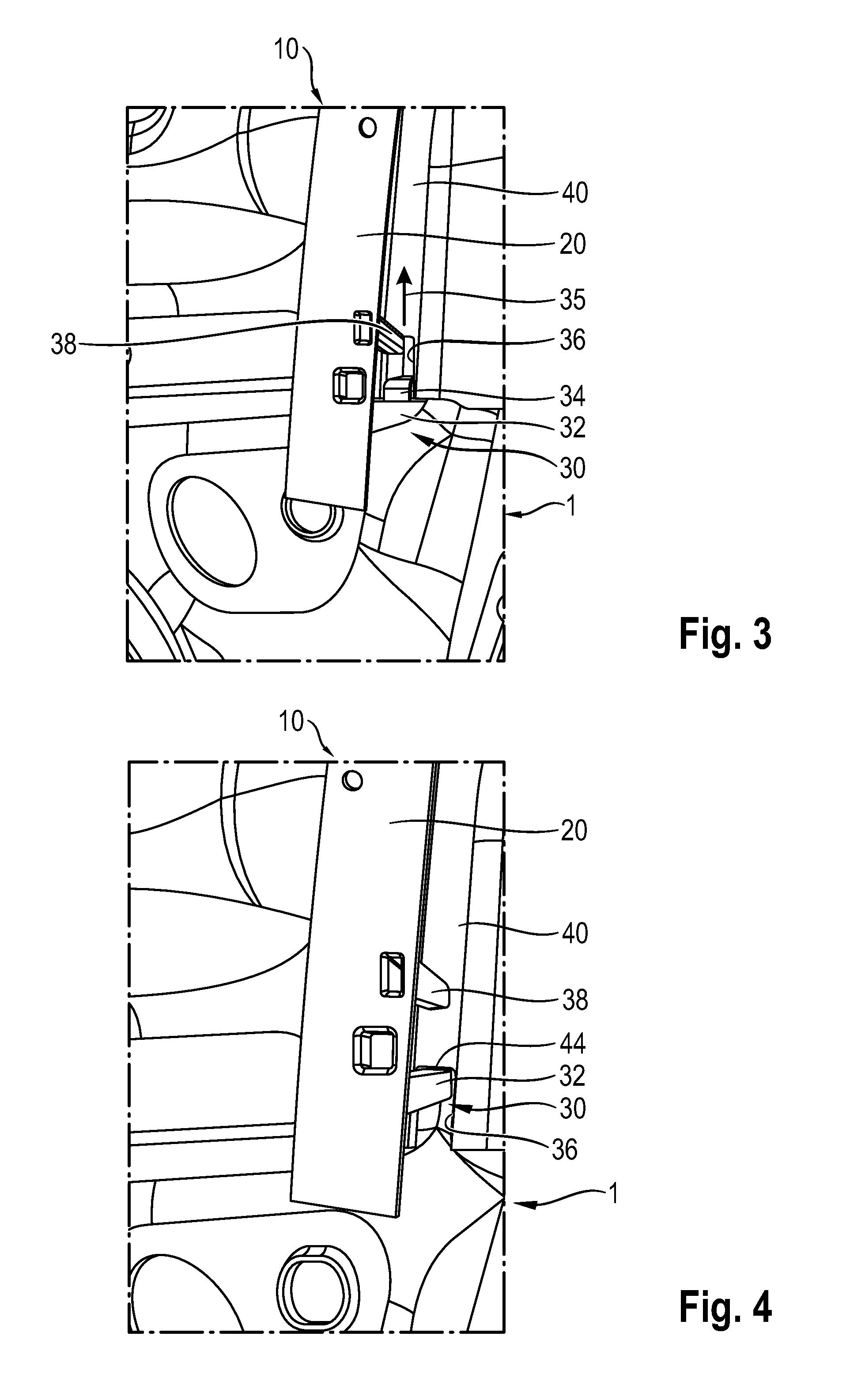
FIG. 3 is an enlarged detailed from FIG. 2 during installation of the cover panel with the aid of a guiding and positioning protrusion.
FIG. 4 is a detail similar to FIG. 3 showing the guiding and positioning protrusion striking against an end portion of an aperture in a hollow profile of the door frame.
DETAILED DESCRIPTION
FIG. 1 is a perspective illustration of a door frame 1 arranged at the rear of the left side of the motor vehicle. The door frame 1 has a window cutout 3 that is delimited in the rearward direction by a C pillar 5.
A cover panel 10 is fastened on the C pillar 5 of the door frame 1 from the outside, and hence also can be referred to as a C-pillar panel 10. A frame-reinforcement part 12 is fastened on the door frame 1 beneath the window cutout 3 and conceals a lower end portion of the cover panel 10. The frame-reinforcement part 12 is, for example, an external channel or duct reinforcement.
FIG. 2 illustrates on an enlarged scale a detail from FIG. 1 with the cover panel 10, but without the frame-reinforcement part 12. The cover panel 10 comprises an elongate main body 15 that is connected to an end 20 of the cover panel 10 in one piece via a triangular connecting body 18. When the frame-reinforcement part 12 is in the installed state, as seen in FIG. 1, the end 20 of the cover panel 10 is concealed by the frame-reinforcement part 12.
The cover panel 10 is injection molded from plastic, while the door frame 1 is formed from a sheet metal material, such as an aluminum sheet material.
The cover panel 10 has a total of three screw-connection locations 21, 22, 23 that receive screws for fastening the cover panel 10 on the door frame 1. The screw-connection location 21 is provided on the elongate main body 15 of the cover panel 10. The two screw-connection locations 22 and 23 are provided on the triangular connecting body 18 of the cover panel 10.
FIGS. 3 and 4 show that a guiding and positioning protrusion 30 is provided at the end 20 of the cover panel 10. Starting from the end 20 of the cover panel 10, the guiding and positioning protrusion 30 projects essentially perpendicularly from said end. The guiding and positioning protrusion 30 has a hook-like profile 32 that defines a step 34.
An arrow 35 is used in FIG. 3 to indicate an installation direction. During installation, the guiding and positioning protrusion 30 is introduced into an aperture 36 in the installation direction 35. The aperture 36 is provided on a hollow profile 40 of the door frame 1 and has an essentially rectangular cross section.
A supporting body 38 is formed at the end 20 of the cover panel 10, in FIGS. 3 and 4 above the guiding and positioning protrusion 30. The supporting body 38 projects essentially perpendicularly from the end 20 of the cover panel 10. During installation, the cover panel 10 is supported on the hollow profile 40 of the door frame 1 by way of the supporting body 38.
FIG. 3 shows that the guiding and positioning protrusion 30 is guided in the aperture 36 during installation of the cover panel 10. During installation, the cover panel 10 is moved up in the installation direction 35, by way of the guiding and positioning protrusion 30, until the guiding and positioning protrusion 30 strikes against an end portion 44 of the aperture 36 in the region of the step 34, as can be seen in FIG. 4.
The hook-like profile 32 of the guiding and positioning protrusion 30 advantageously engages in the hollow profile 40 by way of the step 34. During and following installation, the cover panel 10 is supported externally on the hollow profile 40, by way of the supporting body 38, in the y direction, which is the transverse direction of the vehicle.
As soon as the correct installation position of the cover panel 10 has been reached, as shown in FIG. 4, the cover panel 10 can be fixed by screws at the screw-connection locations (21 to 23 in FIG. 2).
* * * * *
D00000
D00001
D00002
XML
uspto.report is an independent third-party trademark research tool that is not affiliated, endorsed, or sponsored by the United States Patent and Trademark Office (USPTO) or any other governmental organization. The information provided by uspto.report is based on publicly available data at the time of writing and is intended for informational purposes only.
While we strive to provide accurate and up-to-date information, we do not guarantee the accuracy, completeness, reliability, or suitability of the information displayed on this site. The use of this site is at your own risk. Any reliance you place on such information is therefore strictly at your own risk.
All official trademark data, including owner information, should be verified by visiting the official USPTO website at www.uspto.gov. This site is not intended to replace professional legal advice and should not be used as a substitute for consulting with a legal professional who is knowledgeable about trademark law.