Optical coherence tomography for biological imaging
Black , et al. July 9, 2
U.S. patent number 10,342,491 [Application Number 15/783,800] was granted by the patent office on 2019-07-09 for optical coherence tomography for biological imaging. This patent grant is currently assigned to Avinger, Inc.. The grantee listed for this patent is Avinger, Inc.. Invention is credited to John F. Black, Evangeline Lumabas, Charles W. McNall, Michael H. Rosenthal, John B. Simpson, Maegan K. Spencer, Michael Zung.


View All Diagrams
| United States Patent | 10,342,491 |
| Black , et al. | July 9, 2019 |
Optical coherence tomography for biological imaging
Abstract
Described herein are catheters for use with Optical Coherence Tomography (OCT) that include an optical fiber core having a first refractive index and an interface medium having a second refractive index, where the first and second refractive indexes are mismatched such that receiving electronics configured to receive optical radiation reflected from the reference interface and the target operate in a total noise range that is within 5 dB of the shot noise limit. These OCT catheters may include a silicon die mirror having a reflective coating that is embedded in the interface medium. The optical fiber can be fixed at just the distal end of the catheter, and may be managed within a handle that is attached to the proximal end of the catheter body, and is configured to allow rotation of the both catheter body and the optical fiber relative to the handle.
| Inventors: | Black; John F. (San Mateo, CA), Spencer; Maegan K. (Emerald Hills, CA), Zung; Michael (San Carlos, CA), McNall; Charles W. (Cottonwood Heights, UT), Lumabas; Evangeline (San Jose, CA), Rosenthal; Michael H. (Menlo Park, CA), Simpson; John B. (Woodside, CA) | ||||||||||
|---|---|---|---|---|---|---|---|---|---|---|---|
| Applicant: |
|
||||||||||
| Assignee: | Avinger, Inc. (Redwood City,
CA) |
||||||||||
| Family ID: | 43221019 | ||||||||||
| Appl. No.: | 15/783,800 | ||||||||||
| Filed: | October 13, 2017 |
Prior Publication Data
| Document Identifier | Publication Date | |
|---|---|---|
| US 20180049700 A1 | Feb 22, 2018 | |
Related U.S. Patent Documents
| Application Number | Filing Date | Patent Number | Issue Date | ||
|---|---|---|---|---|---|
| 12790703 | May 28, 2010 | 9788790 | |||
| 61258064 | Nov 4, 2009 | ||||
| 61222238 | Jul 1, 2009 | ||||
| 61182061 | May 28, 2009 | ||||
| Current U.S. Class: | 1/1 |
| Current CPC Class: | A61B 5/0066 (20130101); A61B 5/6852 (20130101) |
| Current International Class: | A61B 5/00 (20060101) |
References Cited [Referenced By]
U.S. Patent Documents
| 3908637 | September 1975 | Doroshow |
| 4178935 | December 1979 | Gekhaman et al. |
| 4487206 | December 1984 | Aagard |
| 4527553 | July 1985 | Upsher |
| 4552554 | November 1985 | Gould et al. |
| 4621353 | November 1986 | Hazel et al. |
| 4639091 | January 1987 | Huignard et al. |
| 4654024 | March 1987 | Crittenden et al. |
| 4686982 | August 1987 | Nash |
| 4691708 | September 1987 | Kane |
| 4771774 | September 1988 | Simpson et al. |
| 4841977 | June 1989 | Griffith et al. |
| 4857046 | August 1989 | Stevens et al. |
| 4920961 | May 1990 | Grossi et al. |
| 4926858 | May 1990 | Gifford, III et al. |
| 5000185 | March 1991 | Yock |
| 5018529 | May 1991 | Tenerz et al. |
| 5041082 | August 1991 | Shiber |
| 5047040 | September 1991 | Simpson et al. |
| 5085662 | February 1992 | Willard |
| 5099850 | March 1992 | Matsui et al. |
| 5178153 | January 1993 | Einzig |
| 5182291 | January 1993 | Gubin et al. |
| 5190050 | March 1993 | Nitzsche |
| 5192291 | March 1993 | Pannek, Jr. |
| 5312415 | May 1994 | Palermo |
| 5312425 | May 1994 | Evans et al. |
| 5321501 | June 1994 | Swanson et al. |
| 5333142 | July 1994 | Scheps |
| 5358472 | October 1994 | Vance et al. |
| 5366464 | November 1994 | Belknap |
| 5383460 | January 1995 | Jang et al. |
| 5383467 | January 1995 | Auer et al. |
| 5425273 | June 1995 | Chevalier |
| 5429136 | July 1995 | Milo et al. |
| 5431673 | July 1995 | Summers et al. |
| 5437284 | August 1995 | Trimble |
| 5459570 | October 1995 | Swanson et al. |
| 5460168 | October 1995 | Masubuchi et al. |
| 5465147 | November 1995 | Swanson |
| 5507795 | April 1996 | Chiang et al. |
| 5556405 | September 1996 | Lary |
| 5607394 | March 1997 | Andersen et al. |
| 5620426 | April 1997 | Braithwaite |
| 5632754 | May 1997 | Farley et al. |
| 5632755 | May 1997 | Nordgren et al. |
| 5674232 | October 1997 | Halliburton |
| 5681336 | October 1997 | Clement et al. |
| 5690634 | November 1997 | Muller et al. |
| 5722403 | March 1998 | McGee et al. |
| 5795295 | August 1998 | Hellmuth et al. |
| 5807339 | September 1998 | Bostrom et al. |
| 5830145 | November 1998 | Tenhoff |
| 5836957 | November 1998 | Schulz et al. |
| 5843050 | December 1998 | Jones et al. |
| 5843103 | December 1998 | Wulfman |
| 5868778 | February 1999 | Gershony et al. |
| 5872879 | February 1999 | Hamm |
| 5904651 | May 1999 | Swanson et al. |
| 5907425 | May 1999 | Dickensheets et al. |
| 5935075 | August 1999 | Casscells et al. |
| 5938602 | August 1999 | Lloyd |
| 5951482 | September 1999 | Winston et al. |
| 5951581 | September 1999 | Saadat et al. |
| 5951583 | September 1999 | Jensen et al. |
| 5956355 | September 1999 | Swanson et al. |
| 5957952 | September 1999 | Gershony et al. |
| 5987995 | November 1999 | Sawatari et al. |
| 5997558 | December 1999 | Nash |
| 6001112 | December 1999 | Taylor |
| 6007530 | December 1999 | Dornhofer et al. |
| 6010449 | January 2000 | Selmon et al. |
| 6013072 | January 2000 | Winston et al. |
| 6017359 | January 2000 | Gershony et al. |
| 6027514 | February 2000 | Stine et al. |
| 6032673 | March 2000 | Savage et al. |
| 6048349 | April 2000 | Winston et al. |
| 6080170 | June 2000 | Nash et al. |
| 6106515 | August 2000 | Winston et al. |
| 6110164 | August 2000 | Vidlund |
| 6120515 | September 2000 | Rogers et al. |
| 6120516 | September 2000 | Selmon et al. |
| 6134002 | October 2000 | Stimson et al. |
| 6134003 | October 2000 | Tearney et al. |
| 6152938 | November 2000 | Curry |
| 6152951 | November 2000 | Hashimoto et al. |
| 6160826 | December 2000 | Swanson et al. |
| 6175669 | January 2001 | Colston et al. |
| 6176871 | January 2001 | Pathak et al. |
| 6183432 | February 2001 | Milo |
| 6193676 | February 2001 | Winston et al. |
| 6206898 | March 2001 | Honeycutt et al. |
| 6228076 | May 2001 | Winston et al. |
| 6241744 | June 2001 | Imran et al. |
| 6283957 | September 2001 | Hashimoto et al. |
| 6290668 | September 2001 | Gregory et al. |
| 6294775 | September 2001 | Seibel et al. |
| 6299622 | October 2001 | Snow et al. |
| 6307985 | October 2001 | Murakami et al. |
| 6402719 | June 2002 | Ponzi et al. |
| 6416527 | July 2002 | Berg et al. |
| 6445939 | September 2002 | Swanson et al. |
| 6445944 | September 2002 | Ostrovsky |
| 6447525 | September 2002 | Follmer et al. |
| 6451036 | September 2002 | Heitzmann et al. |
| 6454717 | September 2002 | Pantages et al. |
| 6454779 | September 2002 | Taylor |
| 6482216 | November 2002 | Hiblar et al. |
| 6482217 | November 2002 | Pintor et al. |
| 6485413 | November 2002 | Boppart et al. |
| 6497649 | December 2002 | Parker et al. |
| 6501551 | December 2002 | Tearney et al. |
| 6503261 | January 2003 | Bruneau et al. |
| 6511458 | January 2003 | Milo et al. |
| 6517528 | February 2003 | Pantages et al. |
| 6542665 | April 2003 | Reed et al. |
| 6546272 | April 2003 | MacKinnon et al. |
| 6551302 | April 2003 | Rosinko et al. |
| 6563105 | May 2003 | Seibel et al. |
| 6564087 | May 2003 | Pitris et al. |
| 6565588 | May 2003 | Clement et al. |
| 6572563 | June 2003 | Ouchi et al. |
| 6572643 | June 2003 | Gharibadeh |
| 6575995 | June 2003 | Huter et al. |
| 6579298 | June 2003 | Bruneau et al. |
| 6615071 | September 2003 | Casscells, III et al. |
| 6638233 | October 2003 | Corvi et al. |
| 6645217 | November 2003 | MacKinnon et al. |
| 6657727 | December 2003 | Izatt |
| 6666874 | December 2003 | Heitzmann et al. |
| 6687010 | February 2004 | Horii |
| 6728571 | April 2004 | Barbato |
| D489973 | May 2004 | Root et al. |
| 6730063 | May 2004 | Delaney et al. |
| 6758854 | July 2004 | Butler et al. |
| 6760112 | July 2004 | Reed et al. |
| 6800085 | October 2004 | Selmon et al. |
| 6818001 | November 2004 | Wulfman et al. |
| 6824550 | November 2004 | Noriega et al. |
| 6830577 | December 2004 | Nash et al. |
| 6845190 | January 2005 | Smithwick et al. |
| 6852109 | February 2005 | Winston et al. |
| 6853457 | February 2005 | Bjarklev et al. |
| 6856712 | February 2005 | Fauver et al. |
| 6867753 | March 2005 | Chinthammit et al. |
| 6879851 | April 2005 | McNamara et al. |
| 6947787 | September 2005 | Webler |
| 6961123 | November 2005 | Wang et al. |
| 6970732 | November 2005 | Winston et al. |
| 6975898 | December 2005 | Seibel |
| 7068878 | June 2006 | Crossman-Bosworth et al. |
| 7074231 | July 2006 | Jang |
| 7126693 | October 2006 | Everett et al. |
| 7172610 | February 2007 | Heitzmann et al. |
| 7242480 | July 2007 | Alphonse |
| 7261687 | August 2007 | Yang |
| 7288087 | October 2007 | Winston et al. |
| 7291146 | November 2007 | Steinke et al. |
| 7297131 | November 2007 | Nita |
| 7311723 | December 2007 | Seibel et al. |
| 7344546 | March 2008 | Wulfman et al. |
| 7366376 | April 2008 | Shishkov et al. |
| 7382949 | June 2008 | Bouma et al. |
| 7426036 | September 2008 | Feldchtein et al. |
| 7428001 | September 2008 | Schowengerdt et al. |
| 7428053 | September 2008 | Feldchtein et al. |
| 7455649 | November 2008 | Root et al. |
| 7474407 | January 2009 | Gutin |
| 7485127 | February 2009 | Nistal |
| 7488340 | February 2009 | Kauphusman et al. |
| 7530948 | May 2009 | Seibel et al. |
| 7530976 | May 2009 | MacMahon et al. |
| 7538859 | May 2009 | Tearney et al. |
| 7538886 | May 2009 | Feldchtein |
| 7539362 | May 2009 | Teramura |
| 7542145 | June 2009 | Toida et al. |
| 7544162 | June 2009 | Ohkubo |
| 7545504 | June 2009 | Buckland et al. |
| 7555333 | June 2009 | Wang et al. |
| 7577471 | August 2009 | Camus et al. |
| 7583872 | September 2009 | Seibel et al. |
| 7616986 | November 2009 | Seibel et al. |
| 7637885 | December 2009 | Maschke |
| 7674253 | March 2010 | Fisher et al. |
| 7682319 | March 2010 | Martin et al. |
| 7706863 | April 2010 | Imanishi et al. |
| 7728985 | June 2010 | Feldchtein et al. |
| 7729745 | June 2010 | Maschke |
| 7734332 | June 2010 | Sher |
| 7738945 | June 2010 | Fauver et al. |
| 7753852 | July 2010 | Maschke |
| 7771425 | August 2010 | Dycus et al. |
| 7785286 | August 2010 | Magnin et al. |
| 7813609 | October 2010 | Petersen et al. |
| 7821643 | October 2010 | Amazeen et al. |
| 7824089 | November 2010 | Charles |
| 7840283 | November 2010 | Bush et al. |
| 7944568 | May 2011 | Teramura et al. |
| 7952718 | May 2011 | Li et al. |
| 7972299 | July 2011 | Carter et al. |
| 8059274 | November 2011 | Splinter |
| 8062316 | November 2011 | Patel et al. |
| 8068921 | November 2011 | Prakash et al. |
| 8313493 | November 2012 | Fisher |
| 8361097 | January 2013 | Patel et al. |
| 8548571 | October 2013 | He et al. |
| 8548603 | October 2013 | Swoyer et al. |
| 8632557 | January 2014 | Thatcher et al. |
| 8644913 | February 2014 | Simpson et al. |
| 8696695 | April 2014 | Patel et al. |
| 8911459 | December 2014 | Simpson et al. |
| 9125562 | September 2015 | Spencer et al. |
| 9345398 | May 2016 | Tachibana et al. |
| 9345406 | May 2016 | Spencer et al. |
| 9345510 | May 2016 | Patel et al. |
| 9498247 | November 2016 | Patel et al. |
| 9498600 | November 2016 | Rosenthal et al. |
| 9557156 | January 2017 | Kankaria |
| 9572492 | February 2017 | Simpson et al. |
| 9592075 | March 2017 | Simpson et al. |
| 9642646 | May 2017 | Patel et al. |
| 9788790 | October 2017 | Black et al. |
| 2001/0020126 | September 2001 | Swanson et al. |
| 2002/0019644 | February 2002 | Hastings et al. |
| 2002/0072706 | June 2002 | Hiblar et al. |
| 2002/0082626 | June 2002 | Donohoe et al. |
| 2002/0111548 | August 2002 | Swanson et al. |
| 2002/0115931 | August 2002 | Strauss et al. |
| 2002/0147459 | October 2002 | Bashiri et al. |
| 2002/0158547 | October 2002 | Wood |
| 2003/0002638 | January 2003 | Mawatari |
| 2003/0028100 | February 2003 | Tearney et al. |
| 2003/0032880 | February 2003 | Moore |
| 2003/0045835 | March 2003 | Anderson et al. |
| 2003/0095248 | May 2003 | Frot |
| 2003/0097044 | May 2003 | Rovegno |
| 2003/0120150 | June 2003 | Govari |
| 2003/0120295 | June 2003 | Simpson et al. |
| 2003/0125756 | July 2003 | Shturman et al. |
| 2003/0125757 | July 2003 | Patel et al. |
| 2003/0125758 | July 2003 | Simpson et al. |
| 2003/0181855 | September 2003 | Simpson et al. |
| 2004/0002650 | January 2004 | Mandrusov et al. |
| 2004/0039371 | February 2004 | Tockman et al. |
| 2004/0057667 | March 2004 | Yamada |
| 2004/0059257 | March 2004 | Gaber |
| 2004/0082850 | April 2004 | Bonner et al. |
| 2004/0092915 | May 2004 | Levatter |
| 2004/0093001 | May 2004 | Hamada |
| 2004/0147934 | July 2004 | Kiester |
| 2004/0167553 | August 2004 | Simpson et al. |
| 2004/0167554 | August 2004 | Simpson et al. |
| 2004/0181249 | September 2004 | Torrance et al. |
| 2004/0186368 | September 2004 | Ramzipoor et al. |
| 2004/0202418 | October 2004 | Ghiron et al. |
| 2004/0220519 | November 2004 | Wulfman et al. |
| 2004/0230212 | November 2004 | Wulfman |
| 2004/0230213 | November 2004 | Wulfman et al. |
| 2004/0236312 | November 2004 | Nistal et al. |
| 2004/0243162 | December 2004 | Wulfman et al. |
| 2004/0254599 | December 2004 | Lipoma et al. |
| 2004/0260236 | December 2004 | Manning et al. |
| 2005/0020925 | January 2005 | Kleen et al. |
| 2005/0043614 | February 2005 | Huizenga et al. |
| 2005/0054947 | March 2005 | Goldenberg |
| 2005/0075660 | April 2005 | Chu et al. |
| 2005/0085708 | April 2005 | Fauver et al. |
| 2005/0085721 | April 2005 | Fauver et al. |
| 2005/0105097 | May 2005 | Fang-Yen et al. |
| 2005/0141843 | June 2005 | Warden et al. |
| 2005/0154407 | July 2005 | Simpson |
| 2005/0159712 | July 2005 | Andersen |
| 2005/0159731 | July 2005 | Lee |
| 2005/0171478 | August 2005 | Selmon et al. |
| 2005/0177068 | August 2005 | Simpson |
| 2005/0182295 | August 2005 | Soper et al. |
| 2005/0187571 | August 2005 | Maschke |
| 2005/0192496 | September 2005 | Maschke |
| 2005/0201662 | September 2005 | Petersen et al. |
| 2005/0203553 | September 2005 | Maschke |
| 2005/0222519 | October 2005 | Simpson |
| 2005/0222663 | October 2005 | Simpson et al. |
| 2005/0251116 | November 2005 | Steinke et al. |
| 2006/0032508 | February 2006 | Simpson |
| 2006/0046235 | March 2006 | Alexander |
| 2006/0049587 | March 2006 | Cornwell |
| 2006/0064009 | March 2006 | Webler et al. |
| 2006/0084911 | April 2006 | Belef et al. |
| 2006/0109478 | May 2006 | Tearney et al. |
| 2006/0135870 | June 2006 | Webler |
| 2006/0173475 | August 2006 | Lafontaine et al. |
| 2006/0229646 | October 2006 | Sparks |
| 2006/0229659 | October 2006 | Gifford et al. |
| 2006/0235262 | October 2006 | Arnal et al. |
| 2006/0235366 | October 2006 | Simpson |
| 2006/0236019 | October 2006 | Soito et al. |
| 2006/0239982 | October 2006 | Simpson |
| 2006/0241503 | October 2006 | Schmitt et al. |
| 2006/0244973 | November 2006 | Yun |
| 2006/0252993 | November 2006 | Freed et al. |
| 2006/0264741 | November 2006 | Prince |
| 2006/0264743 | November 2006 | Kleen et al. |
| 2006/0264907 | November 2006 | Eskridge et al. |
| 2007/0010840 | January 2007 | Rosenthal et al. |
| 2007/0015969 | January 2007 | Feldman et al. |
| 2007/0015979 | January 2007 | Redel |
| 2007/0035855 | February 2007 | Dickensheets |
| 2007/0038061 | February 2007 | Huennekens et al. |
| 2007/0038125 | February 2007 | Kleen et al. |
| 2007/0038173 | February 2007 | Simpson |
| 2007/0078469 | April 2007 | Soito et al. |
| 2007/0078500 | April 2007 | Ryan et al. |
| 2007/0081166 | April 2007 | Brown et al. |
| 2007/0088230 | April 2007 | Terashi et al. |
| 2007/0106155 | May 2007 | Goodnow et al. |
| 2007/0135712 | June 2007 | Maschke |
| 2007/0196926 | August 2007 | Soito et al. |
| 2007/0219484 | September 2007 | Straub |
| 2007/0250080 | October 2007 | Jones et al. |
| 2007/0255252 | November 2007 | Mehta |
| 2007/0270647 | November 2007 | Nahen et al. |
| 2007/0276419 | November 2007 | Rosenthal |
| 2007/0288036 | December 2007 | Seshadri |
| 2007/0299309 | December 2007 | Seibel et al. |
| 2008/0004643 | January 2008 | To et al. |
| 2008/0004644 | January 2008 | To et al. |
| 2008/0004645 | January 2008 | To et al. |
| 2008/0004646 | January 2008 | To et al. |
| 2008/0015491 | January 2008 | Bei et al. |
| 2008/0027334 | January 2008 | Langston |
| 2008/0033396 | February 2008 | Danek et al. |
| 2008/0045986 | February 2008 | To et al. |
| 2008/0049234 | February 2008 | Seitz |
| 2008/0058629 | March 2008 | Seibel et al. |
| 2008/0065124 | March 2008 | Olson |
| 2008/0065125 | March 2008 | Olson |
| 2008/0065205 | March 2008 | Nguyen et al. |
| 2008/0103439 | May 2008 | Torrance et al. |
| 2008/0103446 | May 2008 | Torrance et al. |
| 2008/0103516 | May 2008 | Wulfman et al. |
| 2008/0139897 | June 2008 | Ainsworth et al. |
| 2008/0146942 | June 2008 | Dala-Krishna |
| 2008/0147000 | June 2008 | Seibel et al. |
| 2008/0154293 | June 2008 | Taylor et al. |
| 2008/0177138 | July 2008 | Courtney et al. |
| 2008/0186501 | August 2008 | Xie |
| 2008/0221388 | September 2008 | Seibel et al. |
| 2008/0228033 | September 2008 | Tumlinson et al. |
| 2008/0243030 | October 2008 | Seibel et al. |
| 2008/0243031 | October 2008 | Seibel et al. |
| 2008/0262312 | October 2008 | Carroll et al. |
| 2008/0275485 | November 2008 | Bonnette et al. |
| 2009/0018565 | January 2009 | To et al. |
| 2009/0018566 | January 2009 | Escudero et al. |
| 2009/0018567 | January 2009 | Escudero et al. |
| 2009/0024084 | January 2009 | Khosla et al. |
| 2009/0024085 | January 2009 | To et al. |
| 2009/0024191 | January 2009 | Seibel et al. |
| 2009/0028407 | January 2009 | Seibel et al. |
| 2009/0028507 | January 2009 | Jones et al. |
| 2009/0073444 | March 2009 | Wang |
| 2009/0093764 | April 2009 | Pfeffer et al. |
| 2009/0099641 | April 2009 | Wu et al. |
| 2009/0125019 | May 2009 | Douglass et al. |
| 2009/0135280 | May 2009 | Johnston et al. |
| 2009/0137893 | May 2009 | Seibel et al. |
| 2009/0152664 | June 2009 | Tian et al. |
| 2009/0185135 | July 2009 | Volk |
| 2009/0196554 | August 2009 | Irisawa |
| 2009/0198125 | August 2009 | Nakabayashi et al. |
| 2009/0208143 | August 2009 | Yoon et al. |
| 2009/0216180 | August 2009 | Lee et al. |
| 2009/0221904 | September 2009 | Shealy et al. |
| 2009/0221920 | September 2009 | Boppart et al. |
| 2009/0235396 | September 2009 | Wang et al. |
| 2009/0244485 | October 2009 | Walsh et al. |
| 2009/0244547 | October 2009 | Ozawa |
| 2009/0264826 | October 2009 | Thompson |
| 2009/0284749 | November 2009 | Johnson et al. |
| 2009/0292199 | November 2009 | Bielewicz et al. |
| 2009/0306520 | December 2009 | Schmitt et al. |
| 2009/0316116 | December 2009 | Melville et al. |
| 2009/0318862 | December 2009 | Ali et al. |
| 2010/0049225 | February 2010 | To et al. |
| 2010/0080016 | April 2010 | Fukui et al. |
| 2010/0125253 | May 2010 | Olson |
| 2010/0130996 | May 2010 | Doud et al. |
| 2010/0241147 | September 2010 | Maschke |
| 2010/0253949 | October 2010 | Adler et al. |
| 2010/0292539 | November 2010 | Lankenau et al. |
| 2010/0292721 | November 2010 | Moberg |
| 2010/0312263 | December 2010 | Moberg et al. |
| 2010/0317973 | December 2010 | Nita |
| 2010/0324472 | December 2010 | Wulfman |
| 2011/0023617 | February 2011 | Yu et al. |
| 2011/0028977 | February 2011 | Rauscher et al. |
| 2011/0040238 | February 2011 | Wulfman et al. |
| 2011/0058250 | March 2011 | Liu et al. |
| 2011/0060186 | March 2011 | Tilson et al. |
| 2011/0071401 | March 2011 | Hastings et al. |
| 2011/0092955 | April 2011 | Purdy et al. |
| 2011/0106004 | May 2011 | Eubanks et al. |
| 2011/0118660 | May 2011 | Torrance et al. |
| 2011/0130777 | June 2011 | Zhang et al. |
| 2011/0144673 | June 2011 | Zhang et al. |
| 2011/0201924 | August 2011 | Tearney et al. |
| 2011/0257478 | October 2011 | Kleiner et al. |
| 2011/0264125 | October 2011 | Wilson et al. |
| 2011/0270187 | November 2011 | Nelson |
| 2011/0295148 | December 2011 | Destoumieux et al. |
| 2011/0301625 | December 2011 | Mauch et al. |
| 2012/0002928 | January 2012 | Irisawa |
| 2012/0238869 | September 2012 | Schmitt et al. |
| 2013/0096589 | April 2013 | Spencer et al. |
| 2013/0138128 | May 2013 | Patel et al. |
| 2013/0296695 | November 2013 | Spencer et al. |
| 2014/0005534 | January 2014 | He et al. |
| 2015/0141816 | May 2015 | Gupta et al. |
| 2015/0208922 | July 2015 | Simpson et al. |
| 2015/0272615 | October 2015 | Newhauser et al. |
| 2015/0320975 | November 2015 | Simpson et al. |
| 2016/0008025 | January 2016 | Gupta et al. |
| 2016/0029902 | February 2016 | Smith et al. |
| 2016/0038030 | February 2016 | Smith et al. |
| 2016/0135832 | May 2016 | Simpson et al. |
| 2016/0144155 | May 2016 | Simpson et al. |
| 2016/0262791 | September 2016 | Patel et al. |
| 2016/0262839 | September 2016 | Spencer et al. |
| 2016/0338582 | November 2016 | Tachibana et al. |
| 2017/0065293 | March 2017 | Rosenthal et al. |
| 2017/0065295 | March 2017 | Patel et al. |
| 2017/0238803 | August 2017 | Kankaria |
| 2017/0238808 | August 2017 | Simpson et al. |
| 2017/0273711 | September 2017 | Simpson et al. |
| 1875242 | Dec 2006 | CN | |||
| 1947652 | Apr 2007 | CN | |||
| 101601581 | Dec 2009 | CN | |||
| 202006018883.5 | Feb 2007 | DE | |||
| 0347098 | Dec 1989 | EP | |||
| 0808638 | Nov 1997 | EP | |||
| 1859732 | Nov 2007 | EP | |||
| 2353526 | Sep 2013 | EP | |||
| S62-275425 | Nov 1987 | JP | |||
| 03502060 | Feb 1990 | JP | |||
| 05103763 | Apr 1993 | JP | |||
| 06027343 | Feb 1994 | JP | |||
| 07308393 | Nov 1995 | JP | |||
| 2002214127 | Jul 2002 | JP | |||
| 2004509695 | Apr 2004 | JP | |||
| 2004516073 | Jun 2004 | JP | |||
| 2005114473 | Apr 2005 | JP | |||
| 2005249704 | Sep 2005 | JP | |||
| 2005533533 | Nov 2005 | JP | |||
| 2008175698 | Jul 2006 | JP | |||
| 2006288775 | Oct 2006 | JP | |||
| 2006313158 | Nov 2006 | JP | |||
| 2006526790 | Nov 2006 | JP | |||
| 2006326157 | Dec 2006 | JP | |||
| 200783053 | Apr 2007 | JP | |||
| 200783057 | Apr 2007 | JP | |||
| 2007225349 | Sep 2007 | JP | |||
| 2007533361 | Nov 2007 | JP | |||
| 2008023627 | Feb 2008 | JP | |||
| 2008128708 | Jun 2008 | JP | |||
| 2008145376 | Jun 2008 | JP | |||
| 2008183208 | Aug 2008 | JP | |||
| 2008253492 | Oct 2008 | JP | |||
| 200914751 | Jan 2009 | JP | |||
| 2009509690 | Mar 2009 | JP | |||
| 200978150 | Apr 2009 | JP | |||
| 2009066252 | Apr 2009 | JP | |||
| 2010042182 | Feb 2010 | JP | |||
| 2010518900 | Jun 2010 | JP | |||
| 2011521747 | Jul 2011 | JP | |||
| 2012533353 | Dec 2012 | JP | |||
| 2007/0047221 | May 2007 | KR | |||
| 2185859 | Jul 2002 | RU | |||
| 2218191 | Dec 2003 | RU | |||
| WO91/17698 | Nov 1991 | WO | |||
| WO99/23958 | May 1999 | WO | |||
| WO00/54659 | Sep 2000 | WO | |||
| WO01/15609 | Mar 2001 | WO | |||
| WO01/76680 | Oct 2001 | WO | |||
| WO2006/133030 | Dec 2006 | WO | |||
| WO2008/005888 | Jan 2008 | WO | |||
| WO2008/029506 | Mar 2008 | WO | |||
| WO2008/042987 | Apr 2008 | WO | |||
| WO2008/051951 | May 2008 | WO | |||
| WO2008/065600 | Jun 2008 | WO | |||
| WO2008/086613 | Jul 2008 | WO | |||
| WO2008/087613 | Jul 2008 | WO | |||
| WO2009/005779 | Jan 2009 | WO | |||
| WO2009/006335 | Jan 2009 | WO | |||
| WO2009/009799 | Jan 2009 | WO | |||
| WO2009/009802 | Jan 2009 | WO | |||
| WO2009/023635 | Feb 2009 | WO | |||
| WO2009/024344 | Feb 2009 | WO | |||
| WO2009/094341 | Jul 2009 | WO | |||
| WO2009/140617 | Nov 2009 | WO | |||
| WO2009/148317 | Dec 2009 | WO | |||
| WO2010/039464 | Apr 2010 | WO | |||
| WO2010/056771 | May 2010 | WO | |||
| WO2011/044387 | Apr 2011 | WO | |||
| WO2011/062087 | May 2011 | WO | |||
Other References
|
Aziz et al.; Chronic total occlusions--a stiff challege requiring a major breakthrough: is there light at the end of the tunnel?; Heart; vol. 91; suppl. III; pp. 42-48; Jun. 2005. cited by applicant . Emkey et al.; Analysis and evaluation of graded-index fiber-lenses; Journal of Lightwave Technology; vol. LT-5; No. 9; pp. 1156-1164; Sep. 1987. cited by applicant . Gonzalo et al.; Optical coherence tomography patterns of stent restenosis; Am. Heart J.; 158(2); pp. 284-293; Aug. 2009. cited by applicant . Han et al.; In situ Frog Retina Imaging Using Common-Path OCT with a Gold-Coated Bare Fiber Probe; CFM6; San Jose, California; CLEO, May 4, 2008; 2 pages. cited by applicant . Linares et al.; Arbitrary single-mode coupling by tapered and nontapered grin fiber lenses; Applied Optics; vol. 29; No. 28; pp. 4003-4007; Oct. 1, 1990. cited by applicant . Muller et al.; Time-gated infrared fourier-domain optical coherence tomography; CFM5; San Jose, California; CLEO May 4, 2008; 2 pages. cited by applicant . Sharma et al.; Optical coherence tomography based on an all-fiber autocorrelator using probe-end reflection as reference; CWJ13; San Francisco, California; CLEO May 16, 2004; 4 pages. cited by applicant . Suparno et al.; Light scattering with single-mode fiber collimators; Applied Optics; vol. 33; No. 30; pp. 7200-7205; Oct. 20, 1994. cited by applicant . Tanaka et al.; Challenges on the frontier of intracoronary imaging: atherosclerotic plaque macrophage measurement by optical coherence tomography; Journal of Biomedical Optics; 15(1); pp. (011104-1)-(011104-8); Jan.-Feb. 2010. cited by applicant . Wang et al.; Common-path endoscopic Fourier domain OCT with a reference Michelson interferometer; Proceedings of the SPIE; vol. 7566; pp. 75660L-75660L-7; Jan. 2010. cited by applicant . Patel et al.; U.S. Appl. No. 15/324,325 entitled "High speed chronic total occulusion crossing devices," filed Jan. 6, 2017. cited by applicant . Patel et al.; U.S. Appl. No. 15/480,238 entitled "Guidewire positioning catheter," filed Apr. 5, 2017. cited by applicant . Smith et al.; U.S. Appl. No. 15/854,579 entitled "Chronic total occlusion crossing devices with imaging," filed Dec. 26, 2017. cited by applicant . Patel et al.; U.S. Appl. No. 15/741,928 entitled "Micro-molded anamorphic reflector lens for image guided therapeutic/diagnostic catheters," filed Jan. 4, 2018. cited by applicant . Zung et al.; U.S. Appl. No. 15/741,773 entitled "Self-alignment mechanism for imaging catheter and drive assembly," filed Jan. 4, 2018. cited by applicant . Patel et al.; U.S. Appl. No. 15/922,058 entitled "Catheter system and method for boring through blocked vascular passages," filed Mar. 15, 2018. cited by applicant. |
Primary Examiner: Santos Rodriguez; Joseph M
Attorney, Agent or Firm: Shay Glenn LLP
Parent Case Text
CROSS REFERENCE TO RELATED APPLICATIONS
This application is a continuation of U.S. patent application Ser. No. 12/790,703, filed May 28, 2010, which claims the benefit of U.S. Provisional Application No. 61/182,061, filed May 28, 2009, U.S. Provisional Application No. 61/258,064, filed Nov. 4, 2009, and U.S. Provisional Application No. 61/222,238, filed Jul. 1, 2009. The disclosures of these applications are incorporated herein by reference in their entirety.
Claims
What is claimed is:
1. A catheter system for optical coherence tomography, comprising: an elongate catheter body; a source of optical radiation; an optical fiber within the elongate catheter body and having a core providing a common path for optical radiation reflected from a reference interface and a target, the core having a first refractive index; receiving electronics configured to receive the optical radiation reflected from the reference interface and the target; and an interface medium at the reference interface and in optical contact with the optical fiber, the interface medium comprising an adhesive having a second refractive index that is different than the first refractive index, wherein the first refractive index and the second refractive index are mismatched such that the receiving electronics operate in a total noise range that is within 5 dB of the shot noise limit; and a processor configured to generate an image of the target based upon the optical radiation received by the receiving electronics.
2. The system of claim 1, wherein the first refractive index and the second refractive index are mismatched such that the receiving electronics operate in a total noise range that is within 3 dB of the shot noise limit.
3. The system of claim 1, wherein the first refractive index and the second refractive index are mismatched such that the receiving electronics operate in a total noise range that is within 2 dB of the shot noise limit.
4. The system of claim 1, wherein the source of optical radiation is a swept-frequency source.
5. The system of claim 1, further comprising a mirror in the interface medium, the mirror configured to reflect the optical radiation from the optical fiber to the target.
6. The system of claim 1, wherein the interface medium is a solid transparent medium.
7. The system of claim 1, wherein the interface medium is in physical contact with a distal end of the core.
8. The system of claim 1, further comprising a directional element configured to relay the optical radiation from the source to a distal end of the core.
9. The system of claim 1, wherein the first refractive index n.sub.1 and the second refractive index n.sub.2 are mismatched such that: .times..times. ##EQU00010## wherein P.sub.in is the power of the optical radiation at the distal end of the optical fiber prior to entering the interface medium, and wherein P.sub.out is the power of the optical radiation reflected from the reference interface such that the receiving electronics operate in a total noise range that is within 5 dB of the shot noise limit.
10. The system of claim 9, wherein the first refractive index n.sub.1 and the second refractive index n.sub.2 are mismatched such that: P.sub.det=P.sub.out(1-L) wherein L is the sum of all the optical losses from the distal end of the probe to the receiving electronics and P.sub.det is the power at the receiving electronics.
11. A catheter for optical coherence tomography, comprising: an elongate catheter body; an optical fiber within the elongate catheter body and having a core providing a common path for optical radiation reflected from a reference interface and a target, the core having a first refractive index; and an interface medium at the reference interface and in optical contact with the optical fiber at a distal end of the optical fiber, the interface medium comprising an adhesive having a second refractive index that is different from the first refractive index, wherein the first refractive index and the second refractive index are mismatched such that receiving electronics in communication with the optical fiber operate in a total noise range that is within 5 dB of the shot noise limit.
12. The catheter of claim 11, wherein the first refractive index and the second refractive index are mismatched such that the receiving electronics operate in a total noise range that is within 3 dB of the shot noise limit.
13. The catheter of claim 11, wherein the first refractive index and the second refractive index are mismatched such that the receiving electronics operate in a total noise range that is within 2 dB of the shot noise limit.
14. The catheter of claim 11, further comprising a mirror in the interface medium, the mirror configured to reflect the optical radiation from the optical fiber to the target.
15. The catheter of claim 11, wherein the interface medium is a solid transparent medium.
16. The catheter of claim 11, wherein the interface medium is in physical and optical contact with a distal end of the core.
17. The catheter of claim 11, wherein the first refractive index n.sub.1 and the second refractive index n.sub.2 are mismatched such that: .times..times. ##EQU00011## wherein P.sub.in is the power of the optical radiation at the distal end of the optical fiber prior to entering the interface medium, and wherein P.sub.out is the power of the optical radiation reflected from the reference interface such that the receiving electronics operate in a total noise range that is within 5 dB of the shot noise limit.
18. The catheter of claim 17, wherein the first refractive index n.sub.1 and the second refractive index n.sub.2 are mismatched such that: P.sub.det=P.sub.out(1-L) wherein L is the sum of all the optical losses from the distal end of the probe to the receiving electronics and P.sub.det is the power at the receiving electronics.
Description
INCORPORATION BY REFERENCE
All publications and patent applications mentioned in this specification are herein incorporated by reference in their entirety to the same extent as if each individual publication or patent application was specifically and individually indicated to be incorporated by reference.
FIELD OF THE INVENTION
Described herein are imaging devices and systems for use in biological probes. In particular, described herein are catheter-based imaging systems using Optical Coherence Tomography (OCT).
BACKGROUND OF THE INVENTION
In cardiovascular surgery, as well as other medical applications, there is frequently a need to extend very thin (few millimeter diameter), long (30-150+ cm) and sterile catheters into thin-walled (e.g., 1-1.5 millimeter wall thickness) biological lumens, including blood vessels such as arteries and veins.
A number of vascular diseases, such as coronary artery disease and peripheral vascular disease, are caused by the build-up of atherosclerotic deposits (plaque) in the arteries, which limit blood flow to the tissues that are supplied by that particular artery. Disorders caused by occluded body vessels, including coronary artery disease (CAD) and peripheral artery disease (PAD) may be debilitating and life-threatening. Chronic Total Occlusion (CTO) can result in limb gangrene, requiring amputation, and may lead to other complications and eventually death. Increasingly, treatment of such blockages may include interventional procedures in which a guidewire is inserted into the diseased artery and threaded to the blocked region. There the blockage may be either expanded into a more open position, for example, by pressure from an inflated catheter balloon (e.g., balloon angioplasty), and/or the blocked region may be held open by a stent. Treatment of such blockages can also include using a catheter to surgically remove the plaque from the inside of the artery (e.g., an atherectomy).
When the artery is totally blocked by plaque, it is extremely difficult, and potentially dangerous to force the guidewire through the occlusion. An obstruction or plaque may be composed of relatively tough fibrous material, often including hard calcium deposits. Forcing a guidewire or catheter past such obstructions may cause the guidewire to puncture the walls of the vessel (e.g., artery) or cause it to enter the layers forming the artery, further damaging the tissue. Thus, there remains a need for guidewire positioning devices that can effectively traverse occluded vessels, and particularly chronically occluded vessels. Such devices would enable positioning of a guidewire and therefore enable positioning of stents and other devices, leading to improved patient outcomes and a reduction in patient morbidity and mortality.
Moreover, there is medical interest in equipping catheter-based cardiovascular catheters with sensors that can help direct atherectomy and other surgical procedures. For example, it would be useful to have sensors that can give the surgeon immediate visual feedback as to whether a particular tissue is diseased and/or how far away the cutting portion of a catheter is from the boundary of a particular blood vessel layer to minimize the risk of accidental damage. Conventional radiological imaging methods and ultrasound imaging systems have been attempted for such surgical procedures. However, neither ultrasound nor radiological imaging methods have enough resolution to help guide the operation of the catheter over the critical last fraction of a millimeter between the interior of a blood vessel and the exterior of the blood vessel. Moreover, standard radiological techniques cannot easily discriminate between healthy tissue and diseased tissue unless the tissue has become heavily calcified. Further, the components of an ultrasound system are generally too large to implement in small dimensions.
Optical Coherence Tomography (OCT) has been proposed as one technique that may be particularly helpful for imaging regions of tissue, including within a body lumen such as a blood vessel. At a basic level, OCT relies on the fact that light traveling from a source and scattering from more distant objects takes longer to travel back than light scattering from nearby objects. Due to the wave nature of light, very small timing differences caused by light signals traveling different distances on the micron scale can cause constructive or destructive interference with reference light signals. OCT systems measure the resulting interference to obtain an image of the target. Unfortunately, however it has thus far proven difficult to provide stable and reliable OCT systems for use in a catheter. A typical OCT system requires one or more interferometers to distinguish the signal from the applied light. In addition, most known OCT systems, when applied to catheters, include a fiber that is rotated (often at high rates) within the catheter in order to scan around a lumen. These systems typically require relatively high power operation, since the many components necessary for rotating and managing the OCT pathway (e.g., fiber) result in optical losses.
Thus, there is a need for efficient and robust OCT systems that are compatible with catheter applications and uses. Described herein are enhanced Optical Coherence Tomography (OCT) systems that that overcome many of the problems described above.
Referring to FIG. 1, a typical OCT device includes a target arm and a reference arm to generate a reference signal. In order to provide the interference reference signal, the OCT device will split an illuminating light signal from the source in two equal or unequal parts, send part of the illuminating light to the target of interest through one target optical "target arm" and send the other part of the illuminating light down a separate reference arm. Light from the separate reference arm reflects off of a mirror, and then returns and interferes with the scattered light that is returning from the target optical arm after bouncing off of the target. In a traditional OCT device, the reference arm length is engineered to be exactly the same length as the target arm so that the interference effect is maximized. The resulting interference between the two beams creates interference effects known as fringes that can be used to measure the relative reflectivity of various layers of the target. Using this information, an image of the object can be generated.
By contrast to the more established applications for OCT, cardiovascular catheters, which are intended for one-time use in blood vessel environments, must be of the highest level of sterility. To obtain such sterility, cardiovascular catheters are typically produced as low-cost disposable items that can be factory sterilized. During a medical procedure, such a catheter is typically removed from the factory sterile container. The proximal end of the catheter is connected to equipment needed to control the catheter (which in this case would also include the link to the OCT engine used to drive any OCT optical fiber in the catheter), and the distal tip is immediately inserted into the patient's body. The catheter is then discarded once the procedure is complete.
Producing low-cost disposable catheters can be difficult as a result of the need for precise reference arm matching and expensive optics. Thus, there is also a need for a low-cost OCT catheter.
SUMMARY OF THE INVENTION
Described herein are OCT catheter, catheter systems, and methods of using and manufacturing them. In general, the OCT catheters and systems described herein are appropriate for use in a patient in order to visualize the internal structures within a lumen of the body in real time. These systems may allow control and navigation of the catheter, including navigation around and through complex anatomy such as bifurcations, ostials, regions of tortuosity, and the like. Further, the real-time and efficient imaging, as well as the control of the imaging system may allow a reduction in procedure time and improvements for long- and short-term outcomes.
In general, a system for optical coherence tomography may include a source of optical radiation, an optical fiber, receiving electronics, an interface medium, and a processor. Typically, the optical fiber has a core providing a common path for optical radiation reflected from a reference interface and a target. The core has a first refractive index. As described herein, the receiving electronics are configured to receive the optical radiation reflected from the reference interface and the target. The interface medium is at the reference interface and in optical contact with the optical fiber. The interface medium has a second refractive index. The first refractive index and the second refractive index are mismatched such that the receiving electronics operate in a total noise range that is within 5 dB of the shot noise limit. The processor generates an image of the target based upon the optical radiation received by the receiving electronics.
This and other embodiments may include one or more of the following features. The first refractive index and the second refractive index can be mismatched such that the receiving electronics operate in a total noise range that is within 3 dB of the shot noise limit. The first refractive index and the second refractive index can be mismatched such that the receiving electronics operate in a total noise range that is within 2 dB of the shot noise limit. The source of optical radiation can be a swept-frequency source.
The system can further include a mirror in the interface medium, and the mirror can be configured to reflect the optical radiation from the optical fiber to the target. The mirror can include a gold-coated silicon die. The interface medium can be a solid transparent medium. The interface medium can be in optical contact with a distal end of the core.
The system can further include a directional element configured to relay the optical radiation from the source to a distal end of the core.
The first refractive index n.sub.1 and the second refractive index n.sub.2 can be mismatched such that:
.times..times. ##EQU00001##
wherein P.sub.in is the power of the optical radiation at the distal end of the optical fiber prior to entering the interface medium, and wherein P.sub.out is the power of the optical radiation reflected from the reference interface such that the receiving electronics operate in a total noise range that is within 5 dB of the shot noise limit. In general, a catheter for use with optical coherence tomography includes an elongate catheter body, an optical fiber in the elongate catheter body, and an interface medium. The optical fiber has a core providing a common path for optical radiation reflected from a reference interface and a target. The core has a first refractive index. The interface medium is in optical contact with the optical fiber. The interface medium has a second refractive index. The first refractive index and the second refractive index are mismatched such that receiving electronics configured to receive optical radiation reflected from the reference interface and the target operate in a total noise range that is within 5 dB of the shot noise limit.
This and other embodiments may include one or more of the following features. The first refractive index and the second refractive index can be mismatched such that the receiving electronics operate in a total noise range that is within 3 dB of the shot noise limit. The first refractive index and the second refractive index can be mismatched such that the receiving electronics operate in a total noise range that is within 2 dB of the shot noise limit.
The system can further include a mirror in the interface medium. The mirror can be configured to reflect the optical radiation from the optical fiber to the target. The mirror can include a gold-coated silicon die. The interface medium can be a solid transparent medium. The interface medium can be in optical contact with a distal end of the core.
The first refractive index n.sub.1 and the second refractive index n.sub.2 can be mismatched such that:
.times..times. ##EQU00002##
wherein P.sub.in is the power of the optical radiation at the distal end of the optical fiber prior to entering the interface medium, and wherein P.sub.out is the power of the optical radiation reflected from the reference interface such that the receiving electronics operate in a total noise range that is within 5 dB of the shot noise limit.
In general, a method of performing optical coherence tomography includes: transmitting optical radiation from a source through an optical fiber having a core, the core having a first refractive index; transmitting the optical radiation from the optical fiber through an interface medium, wherein the interface medium is in optical contact with the optical fiber, the interface medium having a second refractive index; transmitting optical radiation reflected from the target and reflected from a reference interface along a common path in the optical fiber to a detector; receiving the reflected optical radiation at receiving electronics, wherein the first refractive index and the second refractive index are mismatched such that the receiving electronics operate in a total noise range that is within 5 dB of the shot noise limit; and generating an image of the target based upon the reflected optical radiation received by the receiving electronics.
This and other embodiments may include one or more of the following features. The first refractive index and the second refractive index can be mismatched such that the receiving electronics operate in a total noise range that is within 3 dB of the shot noise limit. The first refractive index and the second refractive index can be mismatched such that the receiving electronics operate in a total noise range that is within 2 dB of the shot noise limit.
Transmitting optical radiation can include transmitting optical radiation comprises transmitting swept-source radiation. Transmitting optical radiation from the optical fiber through the interface medium further can include transmitting the optical radiation from the optical fiber to a mirror in the interface medium.
In general, a system for optical coherence tomography includes a source of optical radiation, an optical fiber providing a common path for optical radiation reflected from a reference and a target, a detector to receive the optical radiation reflected from the reference and the target, an interface medium at the reference interface and in optical contact with the distal end of the optical fiber, a mirror in the embedding medium, and a processor to generate an image of the target based upon the optical radiation received by the detector. The mirror includes a silicon die having a reflective coating.
This and other embodiments may include one or more of the following features. The reflective coating can be metallic. The metallic coating can be gold. The reflective coating may be at least
.lamda..times..times..times..times..times..pi. ##EQU00003## .ANG. thick where .lamda..sub.min is the wavelength of light in the optical fiber. The metallic coating can be about 2,800 .ANG. thick.
The system can further include an adhesion layer between the silicon die and the reflective coating. The adhesion layer can include nickel, titanium, or chromium. The adhesion layer can be between 50 .ANG. and 200 .ANG. thick. The adhesion layer can be about 100 .ANG. thick. The interface medium can include an adhesive.
The mirror can be at least 95% reflective, such as at least 98% reflective. The interface medium can be a solid transparent medium. The source of optical radiation can be configured to provide swept-source radiation.
In general, a catheter for use with optical coherence tomography includes an elongate catheter body, an optical fiber in the elongate catheter body, an interface medium, and a mirror in the interface medium. The optical fiber provides a common path for optical radiation reflected from a reference interface and a target. The interface medium is at the reference interface and in optical contact with a distal end of the optical fiber. The mirror includes a silicon die having a reflective coating.
This and other embodiments may include one or more of the following features. The interface medium can include an adhesive. The reflective coating can be metallic. The metallic coating can be gold. The reflective coating can be at least
.lamda..times..pi. ##EQU00004## .ANG. thick where .lamda..sub.min is the wavelength of light in the optical fiber. The reflective coating can be about 2,800 .ANG. thick.
The catheter can further include an adhesion layer between the silicon die and the reflective coating. The adhesion layer can be nickel, titanium, or chromium. The adhesion layer can be between 50 .ANG. and 200 .ANG. thick. The adhesion layer can be about 100 .ANG. thick. The mirror can be at least 95% reflective, such as at least 98% reflective.
In general, a method of performing optical coherence tomography includes transmitting optical radiation from a source through an optical fiber; transmitting the optical radiation from the optical fiber to a mirror embedded in an interface medium, wherein the mirror comprises a silicon die having a reflective coating, and wherein the interface medium is in optical contact with a distal end of a core of the optical fiber; reflecting the optical radiation from the mirror to a target; reflecting the optical radiation from a reference interface, the reference interface between the optical fiber and the interface medium; transmitting optical radiation reflected from the target and reflected from the reference interface along a common path in the optical fiber to a detector; receiving the reflected optical radiation at a detector; and generating an image of the target based upon the reflected optical radiation received by the detector.
This and other embodiments may include one or more of the following features. Transmitting optical radiation can include transmitting swept-source radiation. The reflective coating can be metallic. The metallic coating can be gold. The metallic coating may be at least
.lamda..times..times..times..times..times..pi. ##EQU00005## .ANG. thick where .lamda..sub.min is the wavelength of light in the optical fiber. The metallic coating can be about 2,800 .ANG. thick.
The method can further include an adhesion layer between the silicon die and the reflective coating. The adhesion layer can include nickel, titanium, or chromium. The adhesion layer can be between 50 .ANG. and 200 .ANG. thick. The adhesion layer can be about 100 .ANG. thick. The mirror can be at least 95% reflective, such as at least 98% reflective.
In general, a system for optical coherence tomography includes a source of optical radiation, an elongate catheter body, an optical fiber, a handle attached to the proximal end of the elongate catheter body, a detector, and a processor. The optical fiber extends from a proximal end to a distal end of the elongate catheter body and can be attached to a distal end of the catheter body. The optical fiber provides a common path for optical radiation reflected from a reference and a target. The handle is configured to allow rotation of the catheter body and the optical fiber relative to the handle about a longitudinal axis of the elongate catheter body. The detector receives the optical radiation reflected from the reference and the target. The processor generates an image of the target based upon the optical radiation received by the detector.
This and other embodiments may include one or more of the following features. The optical fiber can be attached to the catheter body only near the distal end of the catheter body. A distal end of the optical fiber can be embedded in a solid transparent medium. The optical fiber can be not coaxial with the elongate catheter body. The handle can include a spooling mechanism, and the spooling mechanism can be configured to spool the optical fiber as it rotates. The handle can include a rotating mechanism, wherein one rotation of the rotating mechanism causes the catheter body and optical fiber to rotate about the longitudinal axis more than one time. One rotation of the rotating mechanism can cause the catheter body and optical fiber to rotate about the longitudinal axis at least two times. One rotation of the rotating mechanism can cause the catheter body and optical fiber to rotate about the longitudinal axis about four times.
In general, a catheter for use with optical coherence tomography includes an elongate catheter body, an optical fiber, and a handle. The optical fiber extends from a proximal end to a distal end of the elongate catheter body and is attached to the catheter body near a near a distal end of the catheter body. The optical fiber provides a common path for optical radiation reflected from a reference and a target. The handle is attached to the proximal end of the elongate catheter body and is configured to allow rotation of the catheter body and the optical fiber relative to the handle about a longitudinal axis of the elongate catheter body.
This and other embodiments may include one or more of the following features. The optical fiber can be attached to the catheter body only near the distal end of the catheter body. A distal end of the optical fiber can be embedded in a solid transparent medium. The optical fiber can be not coaxial with the elongate catheter body.
The handle can include a spooling mechanism, the spooling mechanism configured to spool the optical fiber as it rotates. The handle can include a rotating mechanism. One rotation of the rotating mechanism can cause the catheter body and optical fiber to rotate about the longitudinal axis more than one time. One rotation of the rotating mechanism can cause the catheter body and optical fiber to rotate about the longitudinal axis at least two times. One rotation of the rotating mechanism can cause the catheter body and optical fiber to rotate about the longitudinal axis about four times.
In general, a method of conducting optical coherence tomography includes: transmitting optical radiation from a source through an optical fiber, the optical fiber extending from a proximal end to a distal end of an elongate catheter body, the optical fiber attached to the catheter body near a distal end of the catheter body; transmitting the optical radiation from the optical fiber to a first position on a target; transmitting optical radiation reflected from the target and reflected from a reference along a common path in the optical fiber to a detector; receiving the reflected optical radiation at a detector; generating a first image of the first position of the target based upon the reflected optical radiation received by the detector; and manually rotating the catheter body and the optical fiber about a longitudinal axis of the catheter body such that a second image from a second position on the target can be obtained.
This and other embodiments may include one or more of the following features. Transmitting optical radiation can include transmitting swept-source radiation. Rotating the elongate catheter body and the optical fiber can include rotating a distal end of the catheter body and a distal end of the optical fiber together. Rotating the optical fiber can include spooling the optical fiber around a spooling mechanism of a handle attached to the proximal end of the catheter body. Rotating the elongate body and the optical fiber can include rotating a rotating mechanism of a handle attached to the proximal end of the catheter body such that the elongate body and the optical fiber rotate relative to the handle. Rotating the rotating mechanism once can cause the catheter body and optical fiber to rotate about the longitudinal axis more than one time. Rotating the rotating mechanism once can cause the catheter body and the optical fiber to rotate about the longitudinal axis at least two times. Rotating the mechanism once can cause the catheter body and the optical fiber to rotate about the longitudinal axis about four times.
The embodiments described herein may have one or more of the following advantages.
Using an OCT system with a common path optical fiber and an interface medium having indexes of refraction that are mismatched allows the OCT receiving electronics to operate in a total noise range that is within 5 dB of the shot noise limit. Operating within 5 dB of the shot noise limit advantageously ensures that noise in the receiving electronics is low. Keeping noise in the receiving electronics low results in a higher quality image. When used with an atherectomy catheter, for example, higher quality images advantageously allow for better identification of target tissue.
Using swept source optical radiation and a common path optical fiber as part of an OCT system allows for the use of a significantly simplified optical system compared to standard time-domain OCT embodiments or swept-source embodiments using Michaelson or Mach-Zehnder interferometers. This allows for the most efficient use of optical radiation, which in turn permits well optimized detection of signal and commensurately higher image quality.
Embedding a silicon die having a reflective coating in an interface medium provides a high reflectivity surface for reflection of light from the fiber to the tissue and back from the tissue into the fiber. The high reflectivity surface ensures that a high percentage of light from the source of optical radiation will be reflected and returned from the tissue. Having more light reflected from the target improves the interference fringe contrast, resulting in a higher quality image.
A system for OCT that includes a common path optical fiber attached to a distal end of the catheter body and a handle attached to the proximal end of the elongate catheter body to rotate the catheter and the optical fiber allows the optical fiber to rotate with the catheter body without breaking or stretching. Allowing the optical fiber to rotate with the catheter body ensures that images can be taken at 360.degree. angles about the catheter body. Taking images at 360.degree. angles around the catheter body ensures that more tissue can be imaged. Moreover, including an optical fiber attached to a distal end of the catheter body and a handle attached to the proximal end of the elongate body to rotate the catheter and the optical fiber advantageously avoids having an additional bulky mechanism to rotate the fiber independently of the catheter.
These and other advantages will be apparent from the following description and claims.
BRIEF DESCRIPTION OF THE DRAWINGS
FIG. 1 shows an example of a prior art OCT system.
FIG. 2A shows an exemplary OCT system as described herein.
FIG. 2B is a schematic illustration of an OCT system as described herein.
FIG. 3A shows an exemplary graph of noise in an OCT detector vs. power.
FIG. 3B shows an exemplary graph of a breakdown of the types of noise contributing to the total noise in the graph of FIG. 3A.
FIG. 3C shows a chart including data drawn from the graphs in FIGS. 3A and 3B.
FIG. 4A is a top view of an exemplary mirror at the distal tip of an OCT catheter.
FIG. 4B is a cross-sectional side view the embodiment of FIG. 4A.
FIG. 5 shows a medical (cardiovascular) catheter system equipped with an OCT system.
FIGS. 6A and 6B show an exemplary embodiment of a fiber uptake system.
FIG. 7 shows an exemplary OCT image from an OCT system.
FIG. 8 shows a system for implementing the OCT system and catheter.
FIG. 9 shows one example of an optical circuit.
FIG. 10 is a schematic of an OCT system as described herein.
FIG. 11 illustrates one variation of a handle, including fiber management (spool) elements.
FIG. 12 illustrates one example of the distal end of a catheter as described herein.
DETAILED DESCRIPTION OF THE INVENTION
The Optical Coherence Tomography (OCT) catheters and systems described herein are configured to provide image guided intra-vascular procedures that may be particularly useful for the diagnosis and/or treatment of arterial disease. The systems may include a catheter, an umbilical connection, and a console. The system uses OCT to form an image of the intravascular environment close to the catheter cutter. FIG. 2B shows a schematic of one variations of an OCT system described in greater detail herein.
During intraluminal procedures, such as atherectomy, problems can arise as a result of failure to properly identify target tissue. By using a catheter having a common path optical fiber for OCT, proper identification of target tissue can be improved.
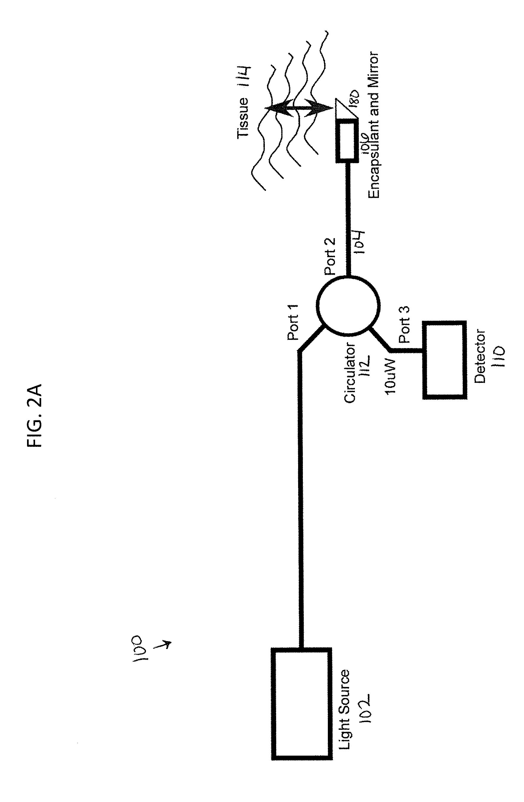
Referring to FIG. 2, a common-path OCT system 100 includes a laser source 102, such as a swept frequency light source. An optical fiber 104 transfers radiation from the laser source 102 to the target 114. The optical fiber 104 is in optical contact with an interface medium 106, i.e. the light exiting the optical fiber and entering the interface medium sees only one interface. In some embodiments, as shown in FIG. 2, the end of the optical fiber is embedded in the interface medium 106.
In the common-path OCT system 100, the index of refraction of the interface medium 106 is different than the index of refraction of the core of the optical fiber 104. This creates a Fresnel reflection, in which part of the light exits the core, and part of the light is reflected back. Some of the light beam that exits the optical fiber 104 will encounter the target 114 and be reflected or scattered by the target 114. Some of this reflected or scattered light will, in turn, reenter the tip of the optical fiber 104 and travel back down the fiber 104 in the opposite direction. A Faraday isolation device 112, such as a Faraday Effect optical circulator, can be used to separate the paths of the outgoing light source signal and the target and reference signals returning from the distal end of the fiber. The reflected or scattered target light and the Fresnel-reflected reference light from the fiber face can travel back to a detector 110 located at the proximal end of the optical fiber 104.
Because the reflected or scattered target light in the OCT system 100 travels a longer distance than the Fresnel reflected reference light, the reflected or scattered target light can be displaced by frequency, phase and or time with respect to the reference beam. For example, if swept-source radiation is used, then the light from the target will be displaced in frequency. The difference in displacement in phase, time or frequency between the reflected or scattered target light and the reference light can be used to derive the path length difference between the end of the optical fiber tip and the light reflecting or light scattering region of the target. In the case of swept source OCT, the displacement is encoded as a beat frequency heterodyned on the carrier reference beam. Embodiments of the above concept where the light paths in the reference and signal arms are common are called common path interferometers. Common path interferometry satisfies the requirements of a low cost disposable device, as it eliminates the separate reference arm but places no additional burden on the catheter construction.
The laser source 102 can operate at a wavelength within the biological window where both hemoglobin and water do not strongly absorb the light, i.e. between 800 nm and 1.4 .mu.m. For example, the laser source 102 can operate at a center wavelength of between about 1300 nm and 1400 nm, such as about 1310 nm to 1340 nm. The optical fiber 104 can be a single mode optical fiber for the ranges of wavelengths provided by the laser source 102.
The core of the optical fiber 104 and the interface medium 106 can have specifically-chosen indexes of reflection such that a known magnitude of Fresnel reflection is created. For example, the indexes of reflection can be chosen such that noise in the OCT system is minimized.
Noise in OCT systems comes from at least three sources: shot noise, thermal or Johnson noise, and residual intensity noise (RIN noise). There may additionally be noise from the analog-to-digital conversion process. RIN noise comes from noise intrinsic to the light source, tends to dominate at high reference powers, and can be limited by limiting the maximum laser light intensity, working with an alternative low RIN light source (non-laser), or by using balanced detection. Thermal (Johnson) noise tends to dominate at low reference power levels, and can be avoided by working at reference power levels yielding a DC photodiode current above that of the thermal noise floor.
Shot noise dominates in between RIN noise and thermal (Johnson) noise. Shot noise is caused by statistical fluctuations in the number of photons or electrons that carry a particular signal. For a well designed system, shot noise is the limiting factor in dynamic range. The indexes of refraction of the fiber 104 and the interface medium 106 can thus be chosen such that the OCT system 100 operates close to the shot noise limit.
The shot noise limit of a particular receiver is set by the responsivity of the photodetector, the detection bandwidth desired, and the reference DC power impinging on the detector element. An exemplary graph of a noise v. power is shown in FIG. 3A with a breakdown by the type of noise shown in FIG. 3B. The graphs in FIGS. 3A and 3B assume a system having 10 mW of forward power, 1550 nm center wavelength, 20 nm bandwidth, 1 MHz detection bandwidth, and a 1 A/W responsivity.
The shot noise limit is the area 301 at the bottom of the curve in FIG. 3A, at which the noise is the lowest or where the degradation from the shot noise limit is the least. Using the graph for a particular receiver, such as the graphs shown in FIG. 3A and FIG. 3B, the desired power at the detector, P.sub.det, can be determined that would place the noise within a desired range of the shot noise limit. For example, FIG. 3C shows a table of values drawn from FIG. 3B. Referring to FIG. 3C, a power of 0.158 .mu.W would place the receiver at the minimum degradation point, 2.36 dB above the shot noise limit. Moreover, reference powers of between 63.1 nW and 251 nW would place the noise within 3 dB of the shot noise limit. Reference powers of between about 25 nW to 0.631 .mu.W would place the noise within 5 dB of the shot noise limit.
To determine the total power, P.sub.out, that must be reflected from the interface 106 to obtain the desired P.sub.det, the losses of the detector 110 must be taken into account according to Equation 1: P.sub.det=P.sub.out(1-L) (equation 1) where P.sub.out is the power reflected from the reference interface, and L is the sum of the optical losses from the distal end of the probe to the detector 110. Therefore, assuming that P.sub.det is equal to 0.2 .mu.W (rounding from the 0.158 .mu.W determined to place the noise as low to the shot noise limit as possible) and that the intermediate optical system operates at 90% efficiency such that L is 10%, P.sub.out is equal to 0.2 .mu.W/(0.9)=0.2222 .mu.W.
The forward power at the distal end of the optical fiber prior to entering the interface medium is given by P.sub.in. Therefore, assume that that P.sub.in is equal to 10 mW.
Moreover, P.sub.out and P.sub.in can be used to determine the reflectivity of the reference interface 180, according to equation 3: P.sub.out=P.sub.inr.sup.2 (equation 3) where r is the Fresnel coefficient of reflectivity. Therefore, assuming that P.sub.out is 0.2222 .mu.W, and P.sub.in is 10 mW, as solved for via equations 2 and 3, then r is equivalent to 0.004714.
Moreover, the Fresnel equation (shown by equation 4) governs the intensity of reflection from a normal or near normal interface:
.times..times. ##EQU00006## where the index of refraction of the transparent medium is given by n.sub.2 and that of the core is n.sub.1.
The index of refraction of the core of the optical fiber, n.sub.1, is fixed by the manufacturer, and varies depending upon the fiber. The optical fiber can be, for example, a Corning SMF-28e, Corning ClearCurve, OFS BF05717 and EZBend, Fujikura SR-15e with enhanced band loss resistance, Draka BendBright XS and BendBright Elite. For Corning SMF-28e, the group refractive index of the core at 1.3 microns is 1.4677. By comparison, a Fujikura ImageFiber has n.sub.1=.about.1.500.
Therefore, assuming that |r| is 0.004714 as solved for with respect to equation 3 and that n.sub.1, is 1.4677, the index of refraction of the interface medium n.sub.2 should be approximately 1.4816 or 1.4539. Thus, an interface medium of either index will produce the desired reference reflection. In some embodiments, the medium with the higher index of refraction may be preferable as it may be more readily available and/or have better mechanical properties, such as tensile strength.
The interface medium used with system 100 can be, for example, an adhesive. Depending upon the required index of refraction, the interface medium can be, for example, M21-CL which is a thermal curing adhesive. Another exemplary interface medium is the Light Weld.RTM. UV curable photonics adhesive OP-4-20658, produced by Dymax corporation, Torrington Conn. This adhesive, which has a refractive index of 1.585 in the cured state, is a rigid clear UV-curable adhesive that can be applied in a liquid form, and which then cures to a rigid form within seconds of exposure to UV light. Another exemplary transparent medium is EpoTek OG127-4 or OG116, produced by Epoxy Technology, Billerica Mass. This has a refractive index of 1.602 in the cured state.
If an interface medium having the exact refractive index desired cannot be found (for example because it does not have the proper tensile strength or is not biocompatible), an interface medium having a refractive index that is close can be selected and the power in, P.sub.in, can be adjusted accordingly. Using the known r and the desired power at the detector, P.sub.det, the required power in P.sub.in can then be determined according to equation 5: P.sub.det=P.sub.inr.sup.2(1-L) (equation 5)
In some implementations, the interface medium can be applied in a semi-liquid state, such as by dispenser, ink jet deposition, spraying, painting, dipping, or other process. The medium may then be cured to a solid form, such as by UV curing, thermal curing, chemical curing, drying, or other process. Other processes, such as vacuum deposition of transparent medium or direct mechanical placement of the transparent medium may also be used.
The interface medium can have a minimum thickness (i.e. depth between the end of the optical fiber and the end of the interface medium) of at least
.lamda..times..times..times..times..times..pi. ##EQU00007## where .lamda..sub.min is the wavelength of light in the optical fiber. For a wavelength of over 1250 nm, this will be approximately 200 nm or greater. The interface medium can also have a thickness that is great enough to introduce an offset between the reference reflection and the minimum distance that the target can approach the distal exit face of the fiber.
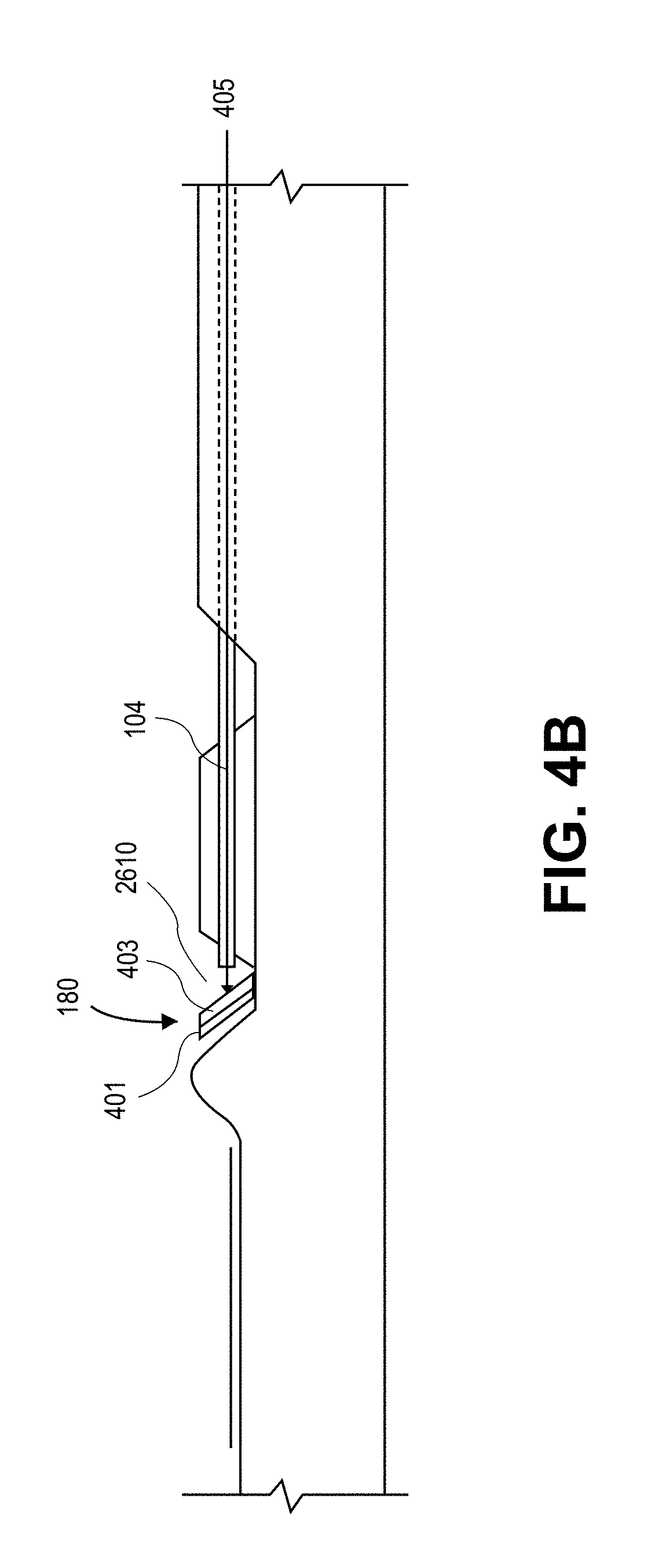
Referring back to FIG. 2 and to FIGS. 4A and 4B, the mirror 180 must be properly designed and optimized in order to fit into the small (approximately 2 mm) diameter of the catheter head and to reflect into a blood vessel tissue located up to 1-3 mm away from the side of the distal catheter tip. As shown in FIG. 4B, the mirror 180 can include a silicon die 401 having a reflective coating 403. The reflective coating 403 can be, for example, a gold coating. The reflective coating 403 can be greater than
.lamda..times..times..times..times..times..pi. ##EQU00008## where .lamda..sub.min is the wavelength of light in the optical fiber. For example, the metallic coating can be greater than about 2,800 .ANG. thick.
Further, the surface of the silicon die 401 under the reflective coating 403 can be polished to less than 400 nm peak-to-peak roughness, such as better than 300 nm peak-to-peak roughness, for example about 200 nm peak-to-peak roughness. An adhesive, such as nickel, titanium, or chromium, can be used to adhere the gold coating to the silicon die. The adhesive can be between about 50 .ANG. and 200 .ANG. thick, such as about 100 .ANG. thick. The mirror 180 of this configuration can be at least 95% reflective, such as 98% reflective.
The mirror 180 can be placed on a slope such that it is at an angle of between 30.degree. and 60.degree., such as 45.degree. with respect to a longitudinal axis 405 of the core of the optical fiber 104. Moreover, the mirror 180 can be configured such that the total distance that the light travels from the fiber 104 to the mirror 180 and out to the sample is between 100 and 400 .mu.m, such as between 200 and 250 .mu.m.
As shown in FIGS. 3A and 3B, the imaging system described herein can be used with a catheter, such as an atherectomy catheter 502. An opening 2610 can be formed in the catheter 502, exposing the distal end of the fiber 104. The OCT mirror 180 can be placed in the opening near the distal tip of the catheter 104, and the interface medium can cover or embed the fiber 502, groove 2608, and opening 2610.
FIG. 5 shows an overview of the main components of an OCT imaging system 500 including a fiber optic catheter 502. The catheter 502 can be sized to fit into a blood vessel, e.g. can be about 2 mm in diameter. In this configuration, the OCT optical apparatus 504 (including the light source, optical circulator, and detectors) can be located at the proximal end of the catheter 502, and can be connected to an image processor and a display 506. The distal end of the catheter 502 includes the image fiber and the mirror. The system 500 is designed to be used within the body of a patient for various medical purposes, such as atherectomy. Thus, other components, such as a vacuum 510, aspiration control 508, and a debris reservoir 512 may be useful.
The system described herein may be used to produce relatively narrow angle images of a portion of an interior lumen of a human body, such as the interior of a blood vessel. Looking at a section of a tissue through a single OCT optical fiber is limited in that the useful angle of view produced by a single OCT optical fiber is at most a few degrees. In order to produce a more medically useful panoramic view of a wide arc or swath from the interior of a blood vessel, such as 45.degree., 90.degree., 120.degree., or more, the catheter containing the optical fiber can be rotated.
Referring to FIGS. 6A and 6B, the catheter 502 can be attached to a fiber uptake system 600. The optical fiber 604 can extend through the catheter 502 and can be attached at the distal end of the catheter 502. The fiber 604 can otherwise be allowed to float freely through the catheter 502, e.g., can be attached only at the distal end of the catheter 502. Doing so prevents build up of optical losses due to microbending or stress-induced birefringence. Further, the fiber 604 can be located off the central longitudinal axis of the catheter 502.
The fiber management system 600 incorporates the fiber on a single internal take-up spool 606. The take-up spool is configured with grooves 608 (see FIG. 6A) sized to fit the optical fiber 604. The optical fiber 608 can move up and down in the grooves 608 (i.e. radially with respect to the catheter 502) to compensate for any bending or stretching of the catheter 502.
The uptake system 600 further includes a physical limiter 610 configured to prohibit the take-up spool from rotating further than the OCT fiber 602 is configured to stretch. Moreover, a torque control knob 614 can be attached to the proximal end of the catheter 502. The knob 614 can be used to actuate rotation of the catheter, and thus rotation of the fiber 604. For example, the knob 614 can be manually activated. The knob 614 can also be motor-driven by a proximal controller 618 to provide a more controlled sector sweep of the imaging element. The knob 614 can be configured such that one rotation of the knob 614 causes the catheter 502 and optical fiber 604 to rotate more than once. For example, the optical fiber 604 can rotate about the longitudinal axis at least two times, such as about four times for every single rotation of the catheter 502.
An encoder 612 in the uptake system 600 detects angle and constantly relays information regarding rotation of the fiber 604 back to the computer controlling the OCT data acquisition system. This value of the angle is incorporated into the display algorithm so as to show a 360 degree view of the inside of the lumen.
Rather than having an encoder 612, the controller 618 can include a "mouse chip" position sensor similar to those used in a computer optical mouse in order to look at the catheter and encode angular and longitudinal motion. The mouse chip can be configured to look at the surface of the catheter (or the braid if the outside laminate is transparent or translucent) and calculate the X and Y motion vectors on the basis of the difference in feature position between adjacent snap-shots.
Rotating the proximal end of the catheter by 360.degree. does not necessarily lead to a 360.degree. rotation at the distal tip, particularly if the catheter is experiencing distributed friction over its length, for example from the introducer sheath, guides, tissue friction especially in a tight lesion. By using a mouse chip, rotation and longitudinal motion of the catheter can be detected while eliminating the unsupported length effect.
An exemplary image or display of a catheter 502 in a lumen 702 is shown in FIG. 7. The display can be continually refreshed by rotating the catheter in either direction. The whole display can also be rotated and oriented with respect to the fluoroscopic view being acquired simultaneously in the cath lab using X-ray. For example, the image may be rotated so that the pericardium is "Up" or "Down". By orienting the display and knowing the spatial relationship between the catheter and the display (and by implication the critical physiological structures in the vessel), the physician may orient the device as required, e.g. to cut an occlusion properly.
The OCT system 100 described herein can produce images, e.g. images of tissue morphology, having a resolution of around 6-15 microns, e.g. 8-10 microns, and to depths of 1-2 mm depending on the optical properties of the sample being imaged. The axial resolution of the OCT system can be about ten times higher than that of a similar ultrasound system.
FIG. 8 shows a system 2700 for implementing the OCT system and catheter described herein. A power supply 2713 supplies power to the OCT engine 2703, the computer processor 2707, and the optical system 2711. A trigger 2701 in the OCT engine 2703 is connected to a trigger 2705 in the computer processor 2707 to begin processing of the image. Moreover, the catheter handle encoder 2715 is attached to the computer processor 2707 to transfer signals related to the location and rotation of the optic fiber. The OCT detector 2717 is attached to the computer processor 2707 to process the final image. Finally, a video signal is sent from the computer processor 2707 to a monitor 2709 to output the image to the user.
In some embodiments, the OCT system and catheter described herein can image up to 1-2 mm in depth with resolutions around 8-10 microns, sufficient to give the physician highly detailed images almost to the cellular organization level and visibility beyond the maximum cut range of the catheter. Moreover, the OCT atherectomy catheter described in can advantageously have imaging capability with crossing-profile impact that is much smaller than traditional OCT systems and ultrasound transducers.
Example
In one example, an image-guided interventional catheter (e.g., an OCT catheter as described above) may be used to address unmet needs in peripheral and coronary artery disease (atherosclerosis). The system may include a console having a modest footprint and in a cath lab without need for extensive integration into cath lab systems. In some variations, the systems described herein may be integrated with other catheter (e.g., guidance, control, imaging) systems. The system may be configured to allow a procedure to start/proceed/finish under fluoro guidance in the event of a system failure. The system is also configured to be compatible with sterile procedures.
As mentioned above, the OCT systems described herein may allow real-time information on intravascular lesion morphology and device orientation in the vessel. This and other features may also allow improved navigation precision around complex anatomy (e.g., bifurcations, ostials, tortuosity, cutting on a curve, etc.), and around stent struts. The catheters may be safely used to traverse diseased tissue while reducing incidence of perforations and dissections potentially associated with a more aggressive treatment strategy. The systems may also provide immediate assessment of acute procedural success, and a reduction in procedure time compared to contemporary interventional techniques. The systems described herein may allow imaging of vessel wall morphology in real time and at a level of precision that could assist the physician in making a "diseased/not-diseased" determination.
In one example, the OCT system is configured to allow tissue morphology to be imaged in real time with resolution routinely around 8-10 microns, and to depths of 1-2 mm depending on the optical properties of the tissue. The axial resolution of OCT is sufficiently high that the images presented to the operator substantially resemble histology from optical microscopy, and are as a result more intuitively interpreted than ultrasound or MRI/CT images. The depth to which OCT can image through tissue with minimal to moderate lipid content is sufficient to give the physician visibility beyond the maximum proposed depth of cut for an atherectomy catheter, allowing the safety margins of the putative cut to be assessed.
As mentioned, OCT has several other technical and economic advantages for catheter applications. The impact on catheter crossing profile of the OCT optical fiber is much smaller than for even the smallest comparable ultrasound transducer. The axial resolution of OCT is typically 10.times. higher than ultrasound; this translates directly to image interpretability. The limited depth of penetration of typical OCT devices is not of primary concern in this application in many applications, because it is known from prior atherectomy procedures that substantial clinical benefit can be obtained by removing several hundred micron thicknesses of tissue. The depth of penetration may be matched to the expected maximum cut depth. Regions of particularly deep or thick tissue (target tissue to be removed) may be identified and treated serially or separately. For example, highly lipid-rich tissues (necrotic cores) appear as dark voids in OCT images, typically with bright caps. [000107] The center wavelength for the optical system may be chosen to provide sufficient depth of penetration, as well as compatibility with the components of the system. For example, the OCT systems may use light that can be transmitted through fused silica fiber optics (where the primary investment in cost and quality has been made). The wavelength range to 250-2000 nm may be particularly useful. Single mode fibers can be readily obtained at any of these wavelength ranges, although wavelengths above 400 nm may be preferable. Other wavelengths could be used, but there may be significant toxicity issues with fiber materials transmitting further into the infrared, and optical sources with the appropriate properties may be difficult to obtain. Below 250 nm air-guiding fibers may be used, however these may be less desirable. In this example, we assume a range of between about 250-2000 nm.
It may be easier to "see" through small annuli of either blood, saline or mixtures by restricting the scan range of the source to regions where hemoglobin and water do not strongly absorb light. This leads to the use of a "biological window" between about 800 nm and 1.4 microns.
The dominant mechanism restricting penetration depth in biological tissue when using ballistic optical scattering techniques is the photon scattering cross-section in the tissue. Higher scattering cross-sections causes fewer photons to traverse from source to target and back ballistically, that is with only one scattering event at the target leading to a reduction in useful signal. The scattering cross-section scales as an inverse power of wavelength over the 250-2000 nm range, transitioning from an exponent of -4 at shorter wavelengths to a smaller value at longer wavelengths. The value decreases monotonically going from short to longer wavelengths so, if our need is to see deeper in tissue, the wavelength range of the source should be biased to longer wavelengths. However, this choice is not without compromise. Moving to longer wavelengths may require a more sophisticated laser source to achieve the same resolution compared to imaging at shorter wavelengths, however this is a soluble technical problem.
In some variations the system takes advantage of the widespread availability of cheap, high quality parts. For example, fiber-based telecommunications has evolved at three specific center wavelength ranges; 800 (LAN only), 1310 (O-band) and 1550 nm (C-band). The systems described herein may restrict the choice of center wavelength to 1310 nm, however this does not mean that the other two wavelength ranges could not be made to work. For example, the 800 nm center wavelength range is routinely used in ophthalmology, where depth of penetration can be sacrificed for tissue layer resolution and where fiber delivery is not a requirement (free-space optics may be used).
In some variations, the system works in the telecommunications O-band. In practice the range of center wavelength is 1315-1340 nm may be dictated by the availability of suitable laser sources in the O-band.
There are three primary categories of source/detector combinations in OCT, namely Time-Domain, Spectral-Domain (Fourier Domain or Spectral Radar) and Swept Source OCT. The examples of OCT systems described herein are swept source OCT (SS-OCT), which allow for video-rate imaging, few or no moving parts, a simple optical system suitable for fiber implementation, imaging to depths greater than 1 mm, and insensitivity to the rigors of a mobile environment.
As discussed above, several interferometer configurations may be used. The systems described herein are Common Path Interferometry (CPI) systems. This has several advantages given the goal of catheter based imaging with cost-constrained capital equipment and disposable devices. The SS-OCT with CPI system described herein preserves the Fellgett Advantage. Fellgett's advantage or the multiplex advantage is an improvement in spectroscopic techniques that is gained when an interferometer is used instead of a monochromator or scanning delay line. The improvement arises because when an interferometer is employed, the radiation that would otherwise be partially or wholly rejected by the monochromator or scanning delay line in its path retains its original intensity. This results in greater efficiency. This embodiment contrasts this with the other systems, in which only a small fraction of the laser power is useful at any given time. For example, the Lightlab.TM. M2 system uses TD-OCT with a scanning delay line, which is equivalent for the purposes of the Fellgett Advantage to a monochromator. Clinically, the Fellgett advantage impacts imaging speed (frame update rate), allowing significant improvements in video display rates which translate to a reduction in ambiguity in interpreting the image.
The CPI systems described herein also preserve the Jacquinot Advantage. The Jacquinot advantage states that in a lossless optical system, the brightness of the object equals the brightness of the image. Assuming that losses due the optical components are negligible, an interferometer's output will be nearly equal in intensity to the input intensity, thus making it easier to detect the signal. This translates directly to image quality, and a more interpretable image.
The CPI system as described herein therefore makes highly efficient use of the laser power. Light is either used for the reference reflection or impinges on the tissue and is used to create signal. No light is lost in attenuators or additional optical components or unused reciprocal paths. This efficient use of laser power is most apparent in the ability of the system to display clinically relevant images of the intravascular environment in real time, without the need for extensive post processing or even on-the-fly image correction.
Furthermore, these systems are "down-lead insensitive", allowing the connection from catheter to console to be of almost arbitrary length without forcing a matched reference delay line to be shipped with each catheter. This minimizes the additional cost impact of the imaging components added to the catheter. It also allows a console component to be positioned almost anywhere, minimizing the potential disruption to work flow and minimizing the threat to a sterile field.
The systems described herein also minimize the number of optical components in the imaging system which could contribute to chromatic aberration. This minimization preserves the spectral fidelity of the laser source optimizing the layer resolution. This translates directly to image quality, and a more interpretable image.
The common-path systems described herein also have exceptional phase stability. Path length changes affecting the sample arm (temperature changes, stress-induced birefringence etc) also affect the reference arm identically. The distance from the ZPD (zero-pathlength difference) point (the reference plane) to the sample is physically fixed and is not subject to variability due to turbulence. This exceptional phase stability coupled with the exceptional phase stability of the OCT engine means that the Z-axis of the display (depth) has minimal jitter, in turn maximizing the real-time interpretability of the image. It also allows us to perform mathematical manipulation of the data that would otherwise be impossible. For example, one advantage of the systems described herein is the ability to perform pre-FFT averaging, which lowers the overall noise floor of the system again translating directly to image quality and interpretability.
In one example, the catheter is around 2 mm in diameter (7F compatible). In a saline-filled lumen, the system will be able to detect an interface (e.g., vessel wall) at 2 mm from the OD of the catheter. In this variation, the following parameters may be used for the catheter and system:
TABLE-US-00001 Specifications Value Optimized Detector Bandwidth DC-10 MHz Nyquist/Shannon rate 20 MHz Minimum number of points to 630 sample for full resolution
The detector may detect optical modulation on the carrier wave from DC to at least 10 MHz with no roll-off in sensitivity. To prevent aliasing (which complicates image interpretation) we may digitize the detector output at a minimum of 20 M-Samples/sec (Nyquist limit) to preserve interpretable real time imaging capability. We may thus capture at least 630 points per laser pulse at this digitizer rate to avoid undersampling the available laser bandwidth.
A practical resolution target is the intima of healthy coronary artery. The system resolution is capable of showing the intima (endothelial layer+internal elastic lamina) as a single sharp bright line on the display.
The system may have an impulse response of 8-10 microns. This resolution dictates the laser scan range requirements and the bandwidth requirements of all the optical components in the fiber harness through the equation:
.differential..times..times..times..pi..times..lamda..times..times..DELTA- ..times..times..lamda. ##EQU00009## Where .delta.z is the axial resolution, .lamda. is the wavelength, .DELTA..lamda. is the wavelength range over which the laser scans, n is the refractive index of the medium and the other symbols have their usual meaning. The origin of this relationship is the Heisenberg Uncertainty Principle. Several observations accrue from this equation.
If the laser scan range .DELTA..lamda. is not broad enough, .delta.z (the resolution) is compromised and an image of a step refractive index discontinuity will be blurred out over many pixels. If any of the optical components in the system restrict (alternatively called clipping or vignetting) the effective bandwidth of the system is reduced and the resolution may suffer. Since the resolution equation has the center wavelength squared in the numerator, as we move to longer center wavelengths for the reasons described above, commensurately larger laser scan range may achieve equivalent axial resolution. Ophthalmology is routinely performed at 800 or 1000 nm center wavelength where there is no need to image deeply into the retina but where the available lasers allow extremely high resolution of the layers of the retina (down to 1-2 microns thickness).
In some variations, the OCT system has a scan range of >100 nm. The theoretical resolution of this engine is 6.35 microns in a medium with a refractive index of 1.35. Stipulating that we digitize at least at the Nyquist limit, fully sample the scanned bandwidth, and that the rescaling procedure in the software does not distort the data, the theoretical resolution of this system is sufficient to show the intima of a healthy coronary at the impulse response limit.
The choice of 1310 nm as a center wavelength for the laser means that we may use standard commercial off-the-shelf telecommunications components which have guaranteed performance at this wavelength and for which standardized test protocols exist. Reasonable and customary incoming inspection procedures can be used to verify that the components going into the system will not deteriorate image quality.
As mentioned above, the system may include receiving electronics including a detector. Assuming that the operating center wavelength is 1315-1340 nm with a full-width half maximum responsivity of >100 nm, and that the detector operates as close as reasonably possible to the shot-noise limited regime, the system may have sufficient trans-impedance gain from the detector to allow the A/D card to operate at an input range where digitizer noise is not a dominant contributor to the noise floor of the system.
Manufacturing tolerances on the catheters will yield a range of distal tip reference reflection intensities. The detector may be configured or chosen so as not to saturate at the high manufacturing limit of the reference reflection power. In one example, the system uses a Fermionics FD80 photodiode in an FC receptacle package as the active element in the photodetector.
The system may also include a fiber harness designed to: 1) provide a low loss pathway from the laser to the catheter, 2) route signal light returning from the catheter to the detector, 3) allow the bleed-in of a red laser diode signal to allow rapid assessment of the integrity of the fiber from cable to distal tip, and 4) provide manufacturing, calibration and field service housekeeping signals to facilitate console production, validation and maintenance.
One primary component of the fiber harness may be a self-contained enclosure with bulkhead FC/APC receptacles on it and containing an optical circuit (such as the one shown in FIG. 9.
In one example, the fiber harness may be connected as: #1 Incoming OCT source (e.g., Santec) Santec output connected here. #2 Diagnostic port (OSA/Photodiode/MZI Calibration); #3 Diagnostic port (OSA/Photodiode/MZI Calibration); #4 Connection to Detector; #5 Reflected FBG Marker (Time/Wavelength Calibration Point); #6 Connection to Catheter; #7 Transmitted FBG Signal (Photodiode scope trigger); #8 Connection to red laser source. Connections may be made with single mode fiber with a cut-off of <1260 nm. The inputs/outputs do not need to be optically isolated.
In some variations, an electrical harness may be used. The electrical harness may be configured to: 1) provide isolation for the various electrical components in the imaging system; 2) distribute 110V to the OCT engine, slave monitor and computer; 3) provide regulated isolated housekeeping power at appropriate voltages and amperages to the detector, red diode laser, catheter handle azimuthal position encoder; 4) send the video signal to the remote monitor; and 5) receive the catheter handle azimuthal angle encoder signal back to the console.
Line power may enter the console through a standard IEC60320 type C14 male power cord entry connector. The power cord used may be Hospital Grade and may have a standard IEC60320 type C13 female connector at the console end. An isolation transformer can distribute LINE power to the OCT engine, slave monitor and computer through IEC standard power cords.
FIG. 10 shows one example of a schematic of an OCT system as described herein. In this example, Items with dotted perimeters are outside the main console chassis enclosure. Analog signal interconnects are to be made with RG58 (U, A/U) patch cables terminated with BNC connectors. The (Santec) Trigger Out signal is a falling edge signal (high Z) and should not be terminated in 50 ohms. The Encoder Signal should be terminated with a MiniCircuits low pass filter module at the A/D card to remove high frequency spurious noise. The Detector Signal should be terminated with a MiniCircuits low pass filter module at the A/D card to remove any noise in an irrelevant frequency range.
FIG. 11 illustrates one variation of a handle, shown schematically. FIG. 12 illustrates one example of the distal end of a catheter as described herein. In this example, the distal end of the catheter includes a fiber having a core that is embedded in a transparent medium as described above. The fiber has an OD of 0.0065'' and is polyimide coated and flat-cleaved (at 90.degree.). The polyimide is stripped from the end to about 500 microns. The mis-match between the refractive indexes of the core and the embedding medium gives a 32-35 dB return loss after curing.
The optical fiber may have a cut-off less than 1260 nm and have single mode performance between 1270 and 1380 nm (and be manufactured compatible with SMF-28 standards). Dissimilar fibers are not preferred as they may populate higher-order spatial modes or generate spurious return loss >65 dB at any given event. The mechanical connections (pigtail and patch cable) may include a simplex cable, and an inner loose tube Teflon Aramid fiber inner annulus to prevent stretching. The outer Jacket may be 2 mm polyurethane. The connector may be a Diamond E2108.6 connector with a 0.25 dB maximum insertion loss and a -65 dB maximum return loss.
The distal tip reference reflection (mirror) may include at least one (1) reflective interface, and may have a return loss of -33.5 dB (Nominal (31-35 dB)). There may be 200-250 microns solid transparent offset from interface to minimum tissue approach point. Interceding optical discontinuities between console and catheter distal tip may be kept to less than 65 dB return loss maximum for any individual surface. The number of reflective interfaces separated by less than 8 mm may be minimized. The parameters above are exemplary only, and may be varied as understood by those of skill in the art, while still remaining in the spirit of the invention as described herein.
The examples and illustrations included herein show, by way of illustration and not of limitation, specific embodiments in which the subject matter may be practiced. Other embodiments may be utilized and derived there from, such that structural and logical substitutions and changes may be made without departing from the scope of this disclosure. Such embodiments of the inventive subject matter may be referred to herein individually or collectively by the term "invention" merely for convenience and without intending to voluntarily limit the scope of this application to any single invention or inventive concept, if more than one is in fact disclosed. Thus, although specific embodiments have been illustrated and described herein, any arrangement calculated to achieve the same purpose may be substituted for the specific embodiments shown. This disclosure is intended to cover any and all adaptations or variations of various embodiments. Combinations of the above embodiments, and other embodiments not specifically described herein, will be apparent to those of skill in the art upon reviewing the above description.
* * * * *
D00000
D00001
D00002
D00003
D00004
D00005
D00006
D00007
D00008
D00009
D00010
D00011
D00012
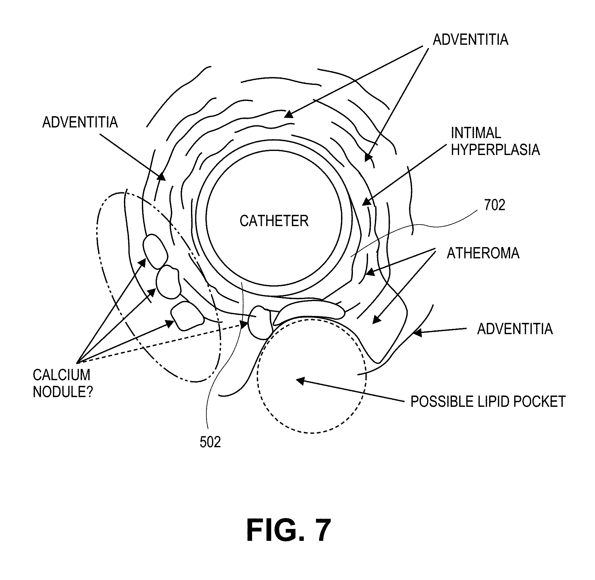
D00013
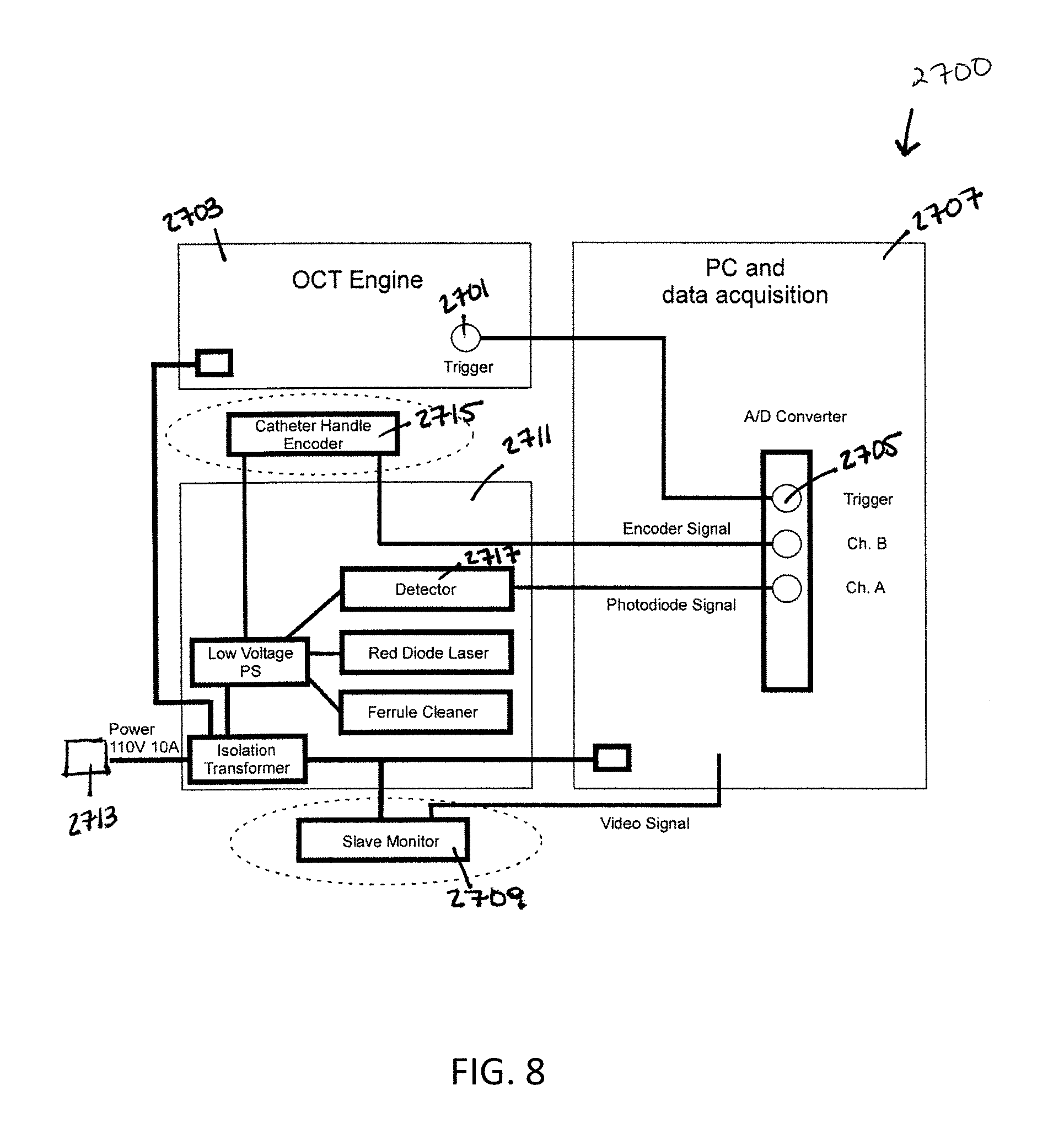
D00014

D00015

D00016

D00017

M00001

M00002

M00003

M00004

M00005

M00006

M00007

M00008

M00009

M00010

M00011

XML
uspto.report is an independent third-party trademark research tool that is not affiliated, endorsed, or sponsored by the United States Patent and Trademark Office (USPTO) or any other governmental organization. The information provided by uspto.report is based on publicly available data at the time of writing and is intended for informational purposes only.
While we strive to provide accurate and up-to-date information, we do not guarantee the accuracy, completeness, reliability, or suitability of the information displayed on this site. The use of this site is at your own risk. Any reliance you place on such information is therefore strictly at your own risk.
All official trademark data, including owner information, should be verified by visiting the official USPTO website at www.uspto.gov. This site is not intended to replace professional legal advice and should not be used as a substitute for consulting with a legal professional who is knowledgeable about trademark law.