Photovoltaic junction box
Zhong , et al.
U.S. patent number 10,340,846 [Application Number 15/245,323] was granted by the patent office on 2019-07-02 for photovoltaic junction box. This patent grant is currently assigned to Tyco Electronics (Shanghai) Co., Ltd.. The grantee listed for this patent is Tyco Electronics (Shanghai) Co. Ltd.. Invention is credited to Cui Li, Wenbo Lv, Xiang Xu, Yuan Zhong.


| United States Patent | 10,340,846 |
| Zhong , et al. | July 2, 2019 |
Photovoltaic junction box
Abstract
A photovoltaic junction box is disclosed. The photovoltaic junction box has a base having a receiving chamber, a cover mounted on the base closing the receiving chamber, and a plurality of ventilation passageways. The plurality of ventilation passageways are disposed between a peripheral edge of the cover and a peripheral edge of the receiving chamber, and communicate between the receiving chamber and an area external of the photovoltaic junction box.
| Inventors: | Zhong; Yuan (Shanghai, CN), Xu; Xiang (Shanghai, CN), Lv; Wenbo (Shanghai, CN), Li; Cui (Shanghai, CN) | ||||||||||
|---|---|---|---|---|---|---|---|---|---|---|---|
| Applicant: |
|
||||||||||
| Assignee: | Tyco Electronics (Shanghai) Co.,
Ltd. (Shanghai, CN) |
||||||||||
| Family ID: | 55298634 | ||||||||||
| Appl. No.: | 15/245,323 | ||||||||||
| Filed: | August 24, 2016 |
Prior Publication Data
| Document Identifier | Publication Date | |
|---|---|---|
| US 20170063299 A1 | Mar 2, 2017 | |
Foreign Application Priority Data
| Aug 26, 2015 [CN] | 2015 2 0650408 U | |||
| Current U.S. Class: | 1/1 |
| Current CPC Class: | H02S 40/34 (20141201); H02S 40/345 (20141201); H02G 3/14 (20130101); Y02E 10/50 (20130101) |
| Current International Class: | H02S 40/34 (20140101); H02G 3/14 (20060101) |
References Cited [Referenced By]
U.S. Patent Documents
| 7824189 | November 2010 | Lauermann |
| 2010/0018572 | January 2010 | Grimberg |
| 2010/0105245 | April 2010 | Good |
| 2010/0263714 | October 2010 | Lauermann |
| 2012/0048615 | March 2012 | Masumoto |
| 2013/0193568 | August 2013 | Yamazaki |
| 2014/0361671 | December 2014 | Degner |
Attorney, Agent or Firm: Barley Snyder
Claims
What is claimed is:
1. A photovoltaic junction box, comprising: a base having a receiving chamber with a peripheral edge surrounding the receiving chamber and a plurality of slots disposed on an outer side of the receiving chamber; a cover fully mounted on the base closing the receiving chamber, the cover having a plurality of resilient protrusions formed on a side of the cover and extending from a peripheral edge of the cover, a portion of the cover disposed between the plurality of resilient protrusions extends beyond the peripheral edge of the cover in a plane of the cover and overlays the peripheral edge of the base when the cover is mounted on the base; and a plurality of ventilation passageways disposed between the peripheral edge of the cover and the peripheral edge of the receiving chamber, the plurality of ventilation passageways integrally formed in at least one of the peripheral edge of the cover and the peripheral edge of the receiving chamber and extending along an entirety of each of a pair of opposite sides of at least one of the peripheral edge of the cover and the peripheral edge of the receiving chamber, the plurality of ventilation passageways communicating between the receiving chamber and an area external of the photovoltaic junction box when the cover is fully mounted on the base.
2. The photovoltaic junction box of claim 1, wherein the plurality of ventilation passageways are formed on the peripheral edge of the cover.
3. The photovoltaic junction box of claim 1, wherein the plurality of ventilation passageways are formed on the peripheral edge of the receiving chamber.
4. The photovoltaic junction box of claim 1, wherein the plurality of ventilation passageways are formed on both the peripheral edge of the cover and the peripheral edge of the receiving chamber.
5. The photovoltaic junction box of claim 1, further comprising a plurality of electronic elements disposed within the receiving chamber.
6. The photovoltaic junction box of claim 5, wherein the electronic elements comprise a plurality of conduction terminals and a plurality of diodes.
7. The photovoltaic junction box of claim 6, wherein each diode connects adjacent conduction terminals.
8. The photovoltaic junction box of claim 7, wherein each diode is soldered on the adjacent conduction terminals.
9. The photovoltaic junction box of claim 8, wherein each diode is directly mounted on surfaces of the adjacent conduction terminals.
10. The photovoltaic junction box of claim 5, wherein the electronic elements are sealed by a sealant poured into the receiving chamber.
11. The photovoltaic junction box of claim 10, wherein the sealant is separated from the cover by a predetermined distance.
12. The photovoltaic junction box of claim 1, wherein the cover is snap-fit to the base.
13. The photovoltaic junction box of claim 12, wherein the plurality of resilient protrusions engage the plurality of slots.
14. The photovoltaic junction box of claim 1, wherein the plurality of ventilation passageways communicate between the receiving chamber and the area external of the photovoltaic junction box in all positions of the cover mounted on the base.
15. The photovoltaic junction box of claim 1, wherein each of the ventilation passageways is a semicircle-shaped hole formed in at least one of the peripheral edge of the cover and the peripheral edge of the receiving chamber.
16. The photovoltaic junction box of claim 1, wherein the plurality of ventilation passageways extend over half of at least one of the peripheral edge of the cover and the peripheral edge of the receiving chamber.
17. The photovoltaic junction box of claim 1, wherein the plurality of ventilation passageways are disposed on the side of the cover having the plurality of resilient protrusions and extend up to a position adjacent each of the plurality of resilient protrusions.
18. The photovoltaic junction box of claim 17, wherein the plurality of ventilation passageways are not disposed on the portion of the cover disposed between the plurality of resilient protrusions.
Description
CROSS-REFERENCE TO RELATED APPLICATION
This application claims the benefit of the filing date under 35 U.S.C. .sctn. 119(a)-(d) of Chinese Patent Application No. 201520650408.3 filed on Aug. 26, 2015.
FIELD OF THE INVENTION
The present invention relates to a photovoltaic junction box, and more particularly, to a photovoltaic junction box capable of being mounted on a solar panel.
BACKGROUND
Solar panels are generally adapted to collect solar energy and transform the collected solar energy to electrical energy. A plurality of solar panels is often connected together by photovoltaic junction boxes to combine the electrical current output of the solar panels.
Known photovoltaic junction boxes have a base and a cover mounted on the base. Electronic elements, such as conduction terminals and diodes, are positioned in a receiving chamber of the base. In the prior art, the base and the cover are engaged with each other hermetically without any gap therebetween, such that the internal space of the photovoltaic junction box is sealed from the external space. However, due to the seal between the base and the cover, heat produced by the diodes during operation is contained within the photovoltaic junction box and is difficult to discharge to the external atmosphere. As the temperature inside the photovoltaic junction box increases, the service life of the diodes and the photoelectric conversion efficiency of the photovoltaic junction box are adversely affected.
SUMMARY
An object of the invention, among others, is to provide a photovoltaic junction box which rapidly dissipates internal heat to the external atmosphere. The disclosed photovoltaic junction box comprises a base having a receiving chamber, a cover mounted on the base closing the receiving chamber, and a plurality of ventilation passageways. The plurality of ventilation passageways are disposed between a peripheral edge of the cover and a peripheral edge of the receiving chamber, and communicate between the receiving chamber and an area external of the photovoltaic junction box.
BRIEF DESCRIPTION OF THE DRAWINGS
The invention will now be described by way of example with reference to the accompanying figures, of which:
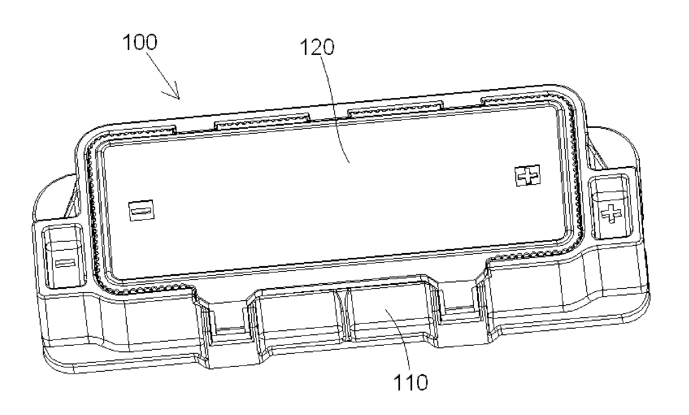
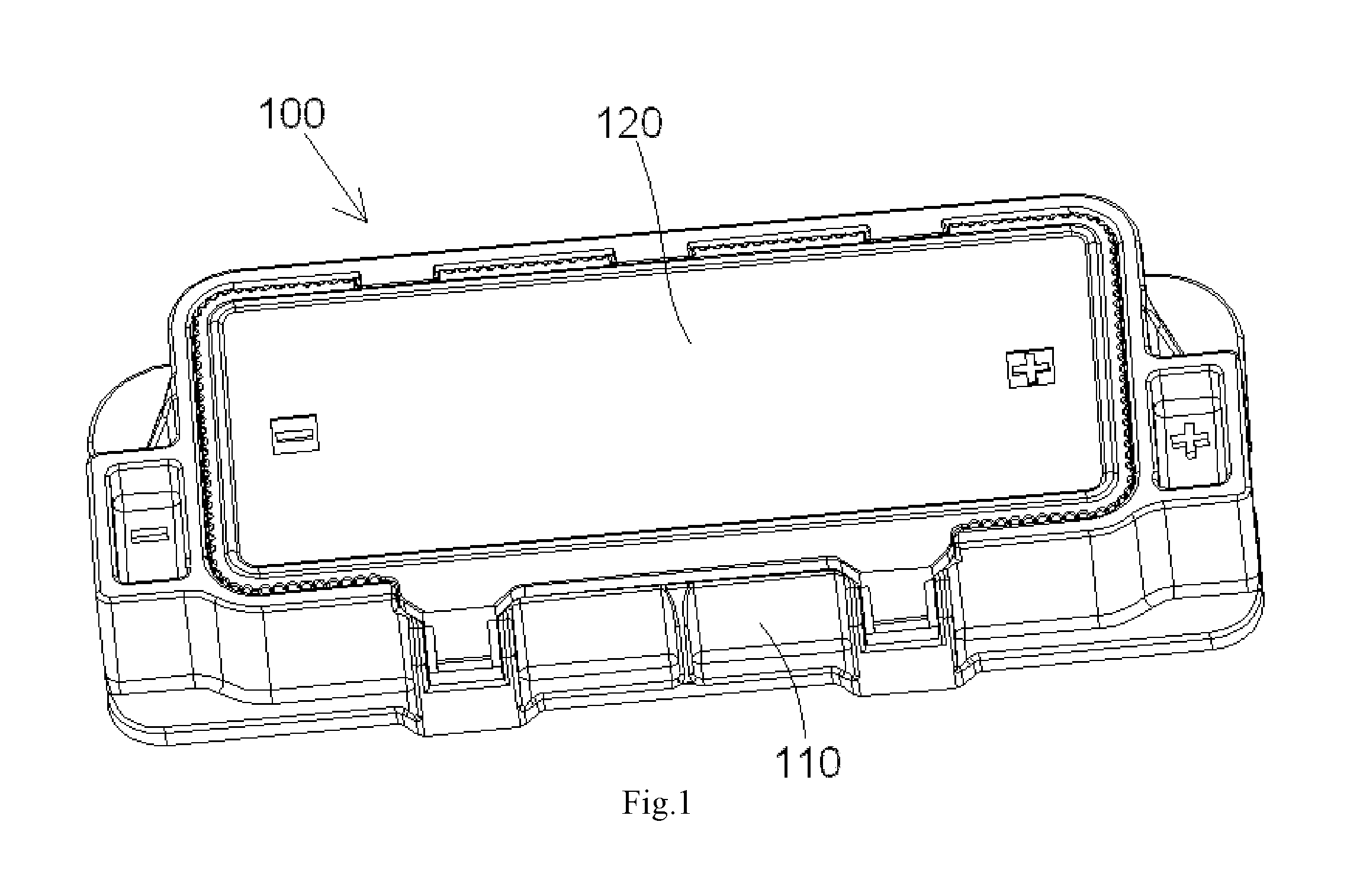
FIG. 1 is a perspective view of a photovoltaic junction box according to the invention;
FIG. 2 is a top plan view of the photovoltaic junction box of FIG. 1;
FIG. 3 is an enlarged perspective view of the photovoltaic junction box of FIG. 1;
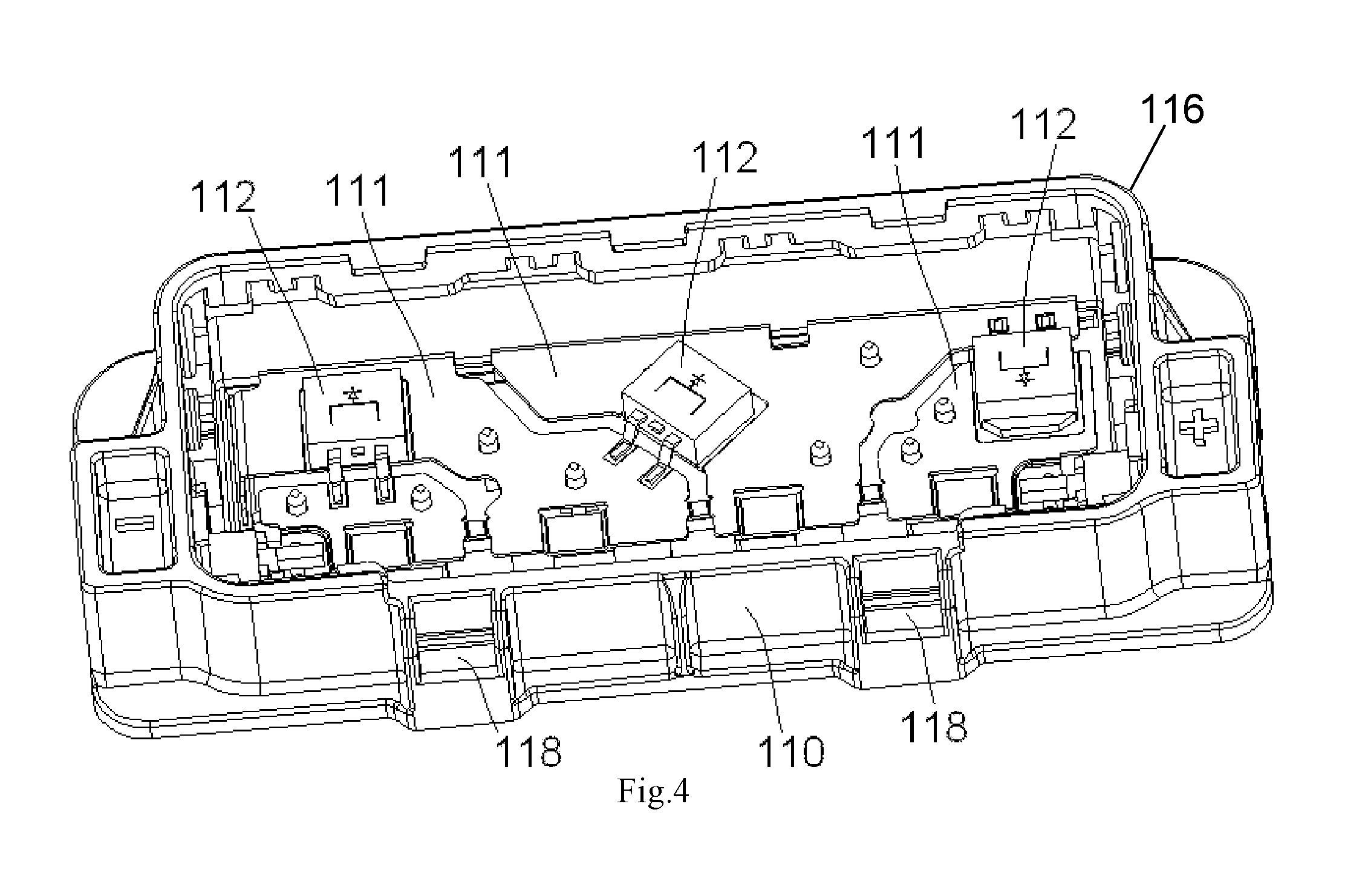
FIG. 4 is a perspective view of a base of the photovoltaic junction box of FIG. 1;
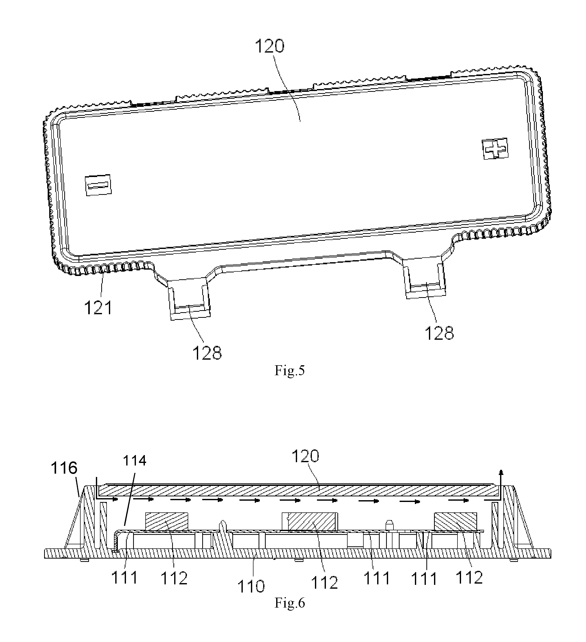
FIG. 5 is a perspective view of a cover of the photovoltaic junction box of FIG. 1; and
FIG. 6 is a sectional view of the photovoltaic junction box of FIG. 1.
DETAILED DESCRIPTION OF THE EMBODIMENT(S)
The invention is explained in greater detail below with reference to embodiments of a photovoltaic junction box. This invention may, however, be embodied in many different forms and should not be construed as limited to the embodiments set forth herein; rather, these embodiments are provided so that this disclosure will be thorough and complete and still fully convey the scope of the invention to those skilled in the art.
A photovoltaic junction box 100 according to the invention is shown generally in FIGS. 1-3. The photovoltaic junction box 100 has a base 110 and a cover 120. The major components of the invention will now be described in greater detail.
The base 110 is shown in FIGS. 1-4 and 6. As shown in FIG. 4, the base 110 has a receiving chamber 116 receiving electronic elements 111, 112. The electronic elements 111, 112, in the shown embodiment, are conduction terminals 111 and diodes 112 connecting adjacent conduction terminals 111. The diodes 112 may be soldered on the conduction terminals 111 by surface-mount technology ("SMT"), such that the diodes 112 are directly mounted on the surface of the conduction terminals 111. In the embodiment shown in FIG. 6, the conduction terminals 111 and diodes 112 are sealed or potted within the base 110 by a sealant 114 poured into the receiving chamber 116. As shown in FIG. 4, the base 110 also has a plurality of slots 118 disposed on an outer side of the base 110.
The cover 120 is shown in FIGS. 1, 2, 3, 5, and 6. As shown in FIG. 5, the cover 120 has a plurality of ventilation passageways 121 formed on and extending through a peripheral edge of the cover 120. In the shown embodiment, the ventilation passageways 121 are formed as semicircle-shaped holes. The ventilation passageways 121 may alternatively be formed on a peripheral edge of the receiving chamber 116 of the base 110, or on both the peripheral edge of the cover 120 and the peripheral edge of the receiving chamber 116. The cover 120 also has a plurality of resilient protrusions 128, as shown in FIG. 5. In the shown embodiment, the resilient protrusions 128 are formed on a side of the cover 120 and extend perpendicular to the cover 120.
As shown in FIGS. 1-3 and 6, the cover 120 is mounted to the base 110. In an embodiment, the cover 120 is mounted to the base 110 by engaging the plurality of resilient protrusions 128 with the plurality of slots 118, for example, by snap-fitting. The cover 120 thus closes the receiving chamber 116.
The use of the photovoltaic junction box 100 will now be described in greater detail.
As shown in FIGS. 1-3, when the cover 120 is mounted to the base 110, the plurality of ventilation passageways 121 are disposed between a peripheral edge of the cover 120 and a peripheral edge of the receiving chamber 116. Due to the plurality of ventilation passageways 121, the receiving chamber 116 communicates with an area external of the photovoltaic junction box 100; external air may thus enter into the photovoltaic junction box 100 via the ventilation passageways 121, and hot air inside the photovoltaic junction box 100 may be discharged to the outside rapidly via the ventilation passageways 121.
As shown in FIG. 6, the sealant 114 is separated from the cover 120 by a predetermined distance so as to allow the air to flow in the receiving chamber 116, and as depicted by the arrows, the air may be circulated in a manner of convection within the photovoltaic junction box 100 and through the ventilation passageways 121. The heat generated by the diodes 112 in operation is quickly brought out of the photovoltaic junction box 100, thereby reducing the temperature inside the photovoltaic junction box 100.
Advantageously, according to the photovoltaic junction box 100 of the present invention, generated heat can be rapidly dissipated via the ventilation passageways 121 to reduce the temperature inside the photovoltaic junction box 100, prolonging the service life of the diodes 112 and improving the photoelectric conversion efficiency of the photovoltaic junction box 100.
* * * * *
D00000
D00001
D00002
D00003
D00004
D00005
XML
uspto.report is an independent third-party trademark research tool that is not affiliated, endorsed, or sponsored by the United States Patent and Trademark Office (USPTO) or any other governmental organization. The information provided by uspto.report is based on publicly available data at the time of writing and is intended for informational purposes only.
While we strive to provide accurate and up-to-date information, we do not guarantee the accuracy, completeness, reliability, or suitability of the information displayed on this site. The use of this site is at your own risk. Any reliance you place on such information is therefore strictly at your own risk.
All official trademark data, including owner information, should be verified by visiting the official USPTO website at www.uspto.gov. This site is not intended to replace professional legal advice and should not be used as a substitute for consulting with a legal professional who is knowledgeable about trademark law.