Lighting assembly with multiple lighting units
Auyeung , et al.
U.S. patent number 10,339,841 [Application Number 15/939,565] was granted by the patent office on 2019-07-02 for lighting assembly with multiple lighting units. This patent grant is currently assigned to Ultravision Technologies, LLC. The grantee listed for this patent is Ultravision Technologies, LLC. Invention is credited to David Siucheong Auyeung, William Y. Hall, Simon Magarill.


View All Diagrams
| United States Patent | 10,339,841 |
| Auyeung , et al. | July 2, 2019 |
Lighting assembly with multiple lighting units
Abstract
A method can be used to illuminate a surface that includes a number of non-overlapping portions. The method includes simultaneously illuminating each of the portions so that the surface is substantially uniformly lit. Each portion is illuminated by a respective lighting assembly. Each lighting assembly includes a plurality of LEDs and a plurality of optical elements proximate the plurality of LEDs. For each lighting assembly, when all LEDs of the lighting assembly are operating, the entire portion of the surface is illuminated with an illumination level and a uniformity. Failure of one or more LEDs of the lighting assembly will cause the illumination level of light impinging the portion of the surface to decrease while the uniformity of light impinging the portion of the surface remains substantially the same.
| Inventors: | Auyeung; David Siucheong (Carrollton, TX), Hall; William Y. (Dallas, TX), Magarill; Simon (Mountain View, CA) | ||||||||||
|---|---|---|---|---|---|---|---|---|---|---|---|
| Applicant: |
|
||||||||||
| Assignee: | Ultravision Technologies, LLC
(Dallas, TX) |
||||||||||
| Family ID: | 49994724 | ||||||||||
| Appl. No.: | 15/939,565 | ||||||||||
| Filed: | March 29, 2018 |
Prior Publication Data
| Document Identifier | Publication Date | |
|---|---|---|
| US 20180218653 A1 | Aug 2, 2018 | |
Related U.S. Patent Documents
| Application Number | Filing Date | Patent Number | Issue Date | ||
|---|---|---|---|---|---|
| 15676823 | Aug 14, 2017 | 9947248 | |||
| 15162278 | Aug 15, 2017 | 9734737 | |||
| 14992680 | May 24, 2016 | 9349307 | |||
| 14635907 | Jan 12, 2016 | 9234642 | |||
| 13836517 | Mar 10, 2015 | 8974077 | |||
| 61677346 | Jul 30, 2012 | ||||
| Current U.S. Class: | 1/1 |
| Current CPC Class: | F21V 29/763 (20150115); F21V 29/15 (20150115); F21V 21/26 (20130101); F21V 29/74 (20150115); F21S 6/006 (20130101); F21V 29/83 (20150115); F21V 31/00 (20130101); F21K 9/60 (20160801); F21V 29/745 (20150115); F21V 29/00 (20130101); G09F 13/22 (20130101); G09F 15/00 (20130101); F21V 29/70 (20150115); F21V 33/00 (20130101); F21V 19/003 (20130101); F21V 29/76 (20150115); F21V 29/89 (20150115); G09F 15/0037 (20130101); F21V 23/002 (20130101); G09F 13/02 (20130101); G09F 15/005 (20130101); F21V 31/005 (20130101); F21V 29/503 (20150115); F21V 5/007 (20130101); F21Y 2105/12 (20160801); G02B 19/0014 (20130101); G09F 2013/222 (20130101); F21W 2131/10 (20130101); F21W 2131/40 (20130101); G02B 19/0028 (20130101); G02B 19/0066 (20130101); F21Y 2115/10 (20160801); F21Y 2105/16 (20160801); F21Y 2105/10 (20160801); G02B 19/0061 (20130101) |
| Current International Class: | F21K 9/60 (20160101); F21V 31/00 (20060101); F21V 33/00 (20060101); G02B 19/00 (20060101); F21V 29/89 (20150101); F21V 29/83 (20150101); F21V 29/76 (20150101); F21V 29/74 (20150101); F21V 29/70 (20150101); F21V 29/15 (20150101); F21V 29/00 (20150101); F21V 23/00 (20150101); F21V 21/26 (20060101); F21V 19/00 (20060101); F21V 5/00 (20180101); F21S 6/00 (20060101); F21V 29/503 (20150101); G09F 15/00 (20060101); G09F 13/02 (20060101); G09F 13/22 (20060101) |
References Cited [Referenced By]
U.S. Patent Documents
| 2254961 | September 1941 | Lawrence et al. |
| 4235285 | November 1980 | Johnson et al. |
| 4679118 | July 1987 | Johnson et al. |
| 5036248 | July 1991 | McEwan et al. |
| 5083194 | January 1992 | Bartilson |
| 5329426 | July 1994 | Villani |
| 5384940 | January 1995 | Soule et al. |
| 5803579 | September 1998 | Turnbull et al. |
| 5818640 | October 1998 | Watanabe et al. |
| 5857767 | January 1999 | Hochstein |
| 5896093 | April 1999 | Sjobom |
| 5924788 | July 1999 | Parkyn, Jr. |
| 5926320 | July 1999 | Parkyn, Jr. et al. |
| 6045240 | April 2000 | Hochstein |
| 6274924 | August 2001 | Carey et al. |
| 6364507 | April 2002 | Yang |
| 6428189 | August 2002 | Hochstein |
| 6517218 | February 2003 | Hochstein |
| 6536923 | March 2003 | Merz |
| 6547423 | April 2003 | Marshall et al. |
| 6582103 | June 2003 | Popovich |
| 6607286 | August 2003 | West et al. |
| 6674096 | January 2004 | Sommers |
| 6741351 | May 2004 | Marshall et al. |
| 6783269 | August 2004 | Pashley et al. |
| 6784603 | August 2004 | Pelka et al. |
| 6799864 | October 2004 | Bohler et al. |
| 6837605 | January 2005 | Reill |
| 6864513 | March 2005 | Lin et al. |
| 6896381 | May 2005 | Benitez et al. |
| 6918684 | July 2005 | Harvey |
| 6948838 | September 2005 | Kunstler |
| 7006306 | February 2006 | Falicoff et al. |
| 7009213 | March 2006 | Camras et al. |
| 7048400 | May 2006 | Murasko et al. |
| 7118236 | October 2006 | Hahm et al. |
| 7144135 | December 2006 | Martin et al. |
| 7153002 | December 2006 | Kim et al. |
| 7159997 | January 2007 | Reo et al. |
| 7246931 | July 2007 | Hsieh et al. |
| 7336195 | February 2008 | van de Ven |
| 7339202 | March 2008 | Chiu et al. |
| 7374306 | May 2008 | Liu |
| 7374316 | May 2008 | Kuo et al. |
| 7375381 | May 2008 | Shimizu et al. |
| 7390117 | June 2008 | Leatherdale et al. |
| 7396146 | July 2008 | Wang |
| 7410275 | August 2008 | Sommers et al. |
| 7434964 | October 2008 | Zheng et al. |
| 7458706 | December 2008 | Liu et al. |
| 7478915 | January 2009 | Pedersen |
| 7513639 | April 2009 | Wang |
| 7513653 | April 2009 | Liu et al. |
| 7549777 | June 2009 | Huang |
| 7572654 | August 2009 | Chang |
| 7618162 | November 2009 | Parkyn et al. |
| 7618163 | November 2009 | Wilcox |
| 7648257 | January 2010 | Villard |
| 7654684 | February 2010 | Wight et al. |
| 7654701 | February 2010 | Zhang et al. |
| 7665862 | February 2010 | Villard |
| 7674019 | March 2010 | Parkyn et al. |
| 7686469 | March 2010 | Ruud et al. |
| 7722224 | May 2010 | Coleman et al. |
| 7736019 | June 2010 | Shimada et al. |
| 7748863 | July 2010 | Holman et al. |
| 7753561 | July 2010 | Chaves et al. |
| 7753564 | July 2010 | Cheng et al. |
| 7794114 | September 2010 | Medendorp, Jr. |
| 7824070 | November 2010 | Higley et al. |
| 7841750 | November 2010 | Wilcox et al. |
| 7857483 | December 2010 | Storch et al. |
| 7862195 | January 2011 | Stack et al. |
| 7866851 | January 2011 | Chang |
| 7896522 | March 2011 | Heller et al. |
| 7905634 | March 2011 | Agurok et al. |
| 7942559 | May 2011 | Holder et al. |
| 7952262 | May 2011 | Wilcox et al. |
| 7959326 | June 2011 | Laporte |
| 7980733 | July 2011 | Shih et al. |
| 7997761 | August 2011 | Peck et al. |
| 8002435 | August 2011 | Laporte |
| 8035119 | October 2011 | Ng et al. |
| 8052303 | November 2011 | Lo et al. |
| 8056614 | November 2011 | Chen et al. |
| 8061869 | November 2011 | Lo |
| 8092049 | January 2012 | Kinnune et al. |
| 8100552 | January 2012 | Spero |
| 8101434 | January 2012 | Guillien et al. |
| 8192048 | June 2012 | Kristoffersen et al. |
| 8201970 | June 2012 | Wang et al. |
| 8210723 | July 2012 | Peck et al. |
| 8215814 | July 2012 | Marcoux |
| 8235546 | August 2012 | Takasago et al. |
| 8235553 | August 2012 | Minami et al. |
| 8246219 | August 2012 | Teng et al. |
| 8256919 | September 2012 | Holder et al. |
| 8262252 | September 2012 | Bergman et al. |
| 8267551 | September 2012 | Lin |
| 8273158 | September 2012 | Jarrier et al. |
| 8308331 | November 2012 | Loh |
| 8310158 | November 2012 | Coplin et al. |
| 8330387 | December 2012 | York et al. |
| 8338841 | December 2012 | Lerman et al. |
| 8342709 | January 2013 | Lueken et al. |
| 8348461 | January 2013 | Wilcox et al. |
| 8360613 | January 2013 | Little, Jr. |
| 8376585 | February 2013 | Noeth |
| 8393101 | March 2013 | Knight et al. |
| 8408737 | April 2013 | Wright et al. |
| 8444297 | May 2013 | Lee et al. |
| 8454194 | June 2013 | Liu |
| 8454215 | June 2013 | Bollmann |
| 8465178 | June 2013 | Wilcox et al. |
| 8469552 | June 2013 | Moeller |
| 8476650 | July 2013 | Liao |
| 8529085 | September 2013 | Josefowicz et al. |
| 8545049 | October 2013 | Davis et al. |
| 8547023 | October 2013 | Chang et al. |
| 8567987 | October 2013 | Wronski |
| 8573815 | November 2013 | Mallory et al. |
| 8577434 | November 2013 | Merchant et al. |
| 8585253 | November 2013 | Duong et al. |
| 8602599 | December 2013 | Zimmer et al. |
| 8610357 | December 2013 | Stoll et al. |
| 8622572 | January 2014 | Morgan |
| 8622574 | January 2014 | Liu |
| 8628217 | January 2014 | Moshtagh |
| 8632225 | January 2014 | Koo et al. |
| 8635049 | January 2014 | Kauffman et al. |
| 8651693 | February 2014 | Josefowicz et al. |
| 8662704 | March 2014 | Carraher et al. |
| 8733981 | May 2014 | Jiang et al. |
| 8789967 | July 2014 | Gordin et al. |
| 8801221 | August 2014 | Lin et al. |
| 8814396 | August 2014 | Ishida et al. |
| 8824125 | September 2014 | Cox et al. |
| 8835958 | September 2014 | Hsieh |
| 8845129 | September 2014 | Holder et al. |
| 8858024 | October 2014 | Wu et al. |
| 8858028 | October 2014 | Kim |
| 8864334 | October 2014 | Swafford, Jr. et al. |
| 8864344 | October 2014 | Jiang et al. |
| 8870410 | October 2014 | Auyeung |
| 8870413 | October 2014 | Auyeung |
| 8876325 | November 2014 | Lu et al. |
| 8899784 | December 2014 | Meyer |
| 8911160 | December 2014 | Seo et al. |
| 8922734 | December 2014 | Lin |
| 8931928 | January 2015 | Heintz |
| 8931934 | January 2015 | Lin |
| 8950921 | February 2015 | Sheng |
| 8956018 | February 2015 | Deshpande et al. |
| 9028097 | May 2015 | Wilcox |
| 9046293 | June 2015 | Pelka et al. |
| 9182101 | November 2015 | Nakamura et al. |
| 9434151 | September 2016 | Tanaka |
| 9464790 | October 2016 | Badley et al. |
| 9523491 | December 2016 | Bailey et al. |
| 9651218 | May 2017 | Gattari |
| 9699854 | July 2017 | Wassel |
| 9739482 | August 2017 | Georgitsis et al. |
| 9752749 | September 2017 | Adams |
| 9791116 | October 2017 | Mrakovich et al. |
| 9822952 | November 2017 | Farmer et al. |
| 9857051 | January 2018 | Ikeda et al. |
| 10012375 | July 2018 | Salessi |
| 2003/0099105 | May 2003 | Watson |
| 2004/0004827 | January 2004 | Guest |
| 2005/0018428 | January 2005 | Harvey |
| 2005/0047170 | March 2005 | Hilburger et al. |
| 2005/0151141 | July 2005 | Grotsch et al. |
| 2005/0128752 | August 2005 | Ewington et al. |
| 2006/0076568 | April 2006 | Keller et al. |
| 2006/0081863 | April 2006 | Kim et al. |
| 2006/0146531 | July 2006 | Reo et al. |
| 2006/0245083 | November 2006 | Chou et al. |
| 2007/0201225 | August 2007 | Holder |
| 2007/0257270 | November 2007 | Lu et al. |
| 2007/0279904 | December 2007 | Tasch et al. |
| 2008/0073663 | March 2008 | Chang |
| 2008/0080179 | April 2008 | Giorgi |
| 2008/0084693 | April 2008 | Shimada et al. |
| 2008/0084701 | April 2008 | Van De Ven et al. |
| 2008/0180014 | July 2008 | Tzeng et al. |
| 2008/0212319 | September 2008 | Klipstein |
| 2008/0247173 | October 2008 | Danek et al. |
| 2008/0273327 | November 2008 | Wilcox et al. |
| 2009/0097265 | April 2009 | Sun et al. |
| 2009/0154158 | June 2009 | Cheng et al. |
| 2009/0180281 | July 2009 | Ahland, III et al. |
| 2009/0256459 | October 2009 | Liu |
| 2009/0262532 | October 2009 | Wilcox et al. |
| 2009/0267474 | October 2009 | Zhou et al. |
| 2009/0273933 | November 2009 | Woodward et al. |
| 2009/0290338 | November 2009 | Heller et al. |
| 2009/0296407 | December 2009 | Bailey |
| 2009/0303711 | December 2009 | Remus et al. |
| 2010/0008094 | January 2010 | Shuai et al. |
| 2010/0014289 | January 2010 | Thomas et al. |
| 2010/0014290 | January 2010 | Wilcox |
| 2010/0002727 | February 2010 | Wilcox et al. |
| 2010/0027271 | February 2010 | Wilcox et al. |
| 2010/0039810 | February 2010 | Holder et al. |
| 2010/0046225 | February 2010 | Zheng |
| 2010/0085774 | April 2010 | Park |
| 2010/0118531 | May 2010 | Montagne |
| 2010/0128488 | May 2010 | Marcoux |
| 2010/0148673 | June 2010 | Stewart et al. |
| 2010/0149801 | June 2010 | Lo et al. |
| 2010/0172135 | July 2010 | Holder et al. |
| 2010/0195330 | August 2010 | Schaefer et al. |
| 2010/0232155 | September 2010 | Wang |
| 2010/0296267 | November 2010 | Yu et al. |
| 2010/0296283 | November 2010 | Taskar et al. |
| 2010/0302785 | December 2010 | Zhou |
| 2010/0302786 | December 2010 | Wilcox et al. |
| 2011/0002120 | January 2011 | Song et al. |
| 2011/0031887 | February 2011 | Stoll et al. |
| 2011/0038151 | February 2011 | Carraher et al. |
| 2011/0063857 | March 2011 | Li et al. |
| 2011/0068708 | March 2011 | Coplin et al. |
| 2011/0075409 | March 2011 | Zheng |
| 2011/0149548 | June 2011 | Yang et al. |
| 2011/0170283 | July 2011 | Chan |
| 2011/0205744 | August 2011 | Kim |
| 2011/0219650 | September 2011 | Wright et al. |
| 2011/0242807 | October 2011 | Little, Jr. et al. |
| 2011/0242816 | October 2011 | Chowdhury et al. |
| 2011/0278633 | November 2011 | Clifford |
| 2011/0280003 | November 2011 | Hsu et al. |
| 2012/0014115 | January 2012 | Park et al. |
| 2012/0043560 | February 2012 | Wu et al. |
| 2012/0080699 | April 2012 | Chowdhury et al. |
| 2012/0087125 | April 2012 | Liu |
| 2012/0163005 | June 2012 | Liu |
| 2012/0192486 | August 2012 | Shanahan et al. |
| 2012/0201022 | August 2012 | van de Ven et al. |
| 2012/0250321 | October 2012 | Blincoe et al. |
| 2012/0307495 | December 2012 | Shih |
| 2013/0010468 | January 2013 | Stoll et al. |
| 2013/0057861 | March 2013 | Ishii et al. |
| 2013/0063970 | March 2013 | Oh |
| 2013/0120991 | May 2013 | Wohlgemuth et al. |
| 2013/0135861 | May 2013 | Chen et al. |
| 2013/0163005 | June 2013 | Tsang |
| 2013/0193850 | August 2013 | Demuynck et al. |
| 2013/0270585 | October 2013 | Mei et al. |
| 2013/0291414 | November 2013 | Cegnar |
| 2013/0335979 | December 2013 | Lauret et al. |
| 2014/0016326 | January 2014 | Dieker et al. |
| 2014/0029253 | January 2014 | Auyeung |
| 2014/0029259 | January 2014 | Auyeung |
| 2014/0029274 | January 2014 | Auyeung |
| 2014/0085905 | March 2014 | Broughton |
| 2014/0104851 | April 2014 | Auyeung |
| 2014/0112007 | April 2014 | Auyeung |
| 2014/0168963 | June 2014 | Stone et al. |
| 2014/0168998 | June 2014 | Tang et al. |
| 2014/0268761 | September 2014 | Raleigh et al. |
| 2014/0293619 | October 2014 | Feng et al. |
| 2014/0373348 | December 2014 | Li |
| 2017/0321869 | November 2017 | Bryant |
| 2615706 | Sep 2006 | CA | |||
| 201925854 | Aug 2011 | CN | |||
| 201973564 | Sep 2011 | CN | |||
| 202629916 | Dec 2012 | CN | |||
| 102889549 | Jan 2013 | CN | |||
| 202005016441 | Feb 2007 | DE | |||
| 1078301 | Feb 2001 | EP | |||
| 1528603 | May 2005 | EP | |||
| 1988576 | Nov 2008 | EP | |||
| 2039985 | Mar 2009 | EP | |||
| 2092859 | Aug 2009 | EP | |||
| 2172696 | Apr 2010 | EP | |||
| 2378337 | Oct 2011 | EP | |||
| 2416062 | Feb 2012 | EP | |||
| 2448021 | May 2012 | EP | |||
| 2553331 | Feb 2013 | EP | |||
| 2622267 | Aug 2013 | EP | |||
| 2421584 | Jun 2006 | GB | |||
| 2003195790 | Jul 2003 | JP | |||
| 2004281352 | Oct 2004 | JP | |||
| 2005024706 | Jan 2005 | JP | |||
| 2005217094 | Aug 2005 | JP | |||
| 2005327820 | Nov 2005 | JP | |||
| 2007035951 | Feb 2007 | JP | |||
| 2007281260 | Oct 2007 | JP | |||
| 2011060575 | Mar 2011 | JP | |||
| 2012054115 | Mar 2012 | JP | |||
| 2012113276 | Jun 2012 | JP | |||
| 20080101832 | Nov 2008 | KR | |||
| 101053785 | Aug 2011 | KR | |||
| 2004051223 | Jun 2004 | WO | |||
| 2006033770 | Mar 2006 | WO | |||
| 2006126123 | Nov 2006 | WO | |||
| 2008047335 | Apr 2008 | WO | |||
| 2008122941 | Oct 2008 | WO | |||
| 2009064607 | May 2009 | WO | |||
| 2010010494 | Jan 2010 | WO | |||
| 2010033545 | Mar 2010 | WO | |||
| 2010130732 | Nov 2010 | WO | |||
| 2011041813 | Apr 2011 | WO | |||
| 2011042837 | Apr 2011 | WO | |||
| 2011123267 | Oct 2011 | WO | |||
| 2012021718 | Feb 2012 | WO | |||
| 2012095242 | Jul 2012 | WO | |||
| 2012121718 | Sep 2012 | WO | |||
Other References
|
"General Catalog--2012," Thorlux Lighting, Dec. 2012, 164 pages. cited by applicant . Tracepro, "LED Reflector and Lens Simulation Usingt TracePro Illumination Design and Analysis Software," White Paper, Oct. 2013, 11 pages. cited by applicant . Tsai, J. et al., "LED Backlight Module by a Lightguide-Diffusive Component With Tetrahedron Reflector Array," J. Display Tech., vol. 8, No. 6, Jun. 2012, pp. 321-328. cited by applicant . Hubbell Lighting, "Universal Lighting Technologies Invention Disclosure," Jun. 14, 2012, 15 pages. cited by applicant . P.R. 4-3 Joint Claim Construction and Prehearing Statement, Ultravision Technologies v. Lamar et al., E.D. Texas, Case No. 2:16-cv-374, filed Jan. 27, 2017, pp. 1-20. cited by applicant . Wang, K et al., "Freeform LED Lens for Rectangularly Prescribed Illumination," J. Opt. A: Pure Appl. Opt., No. 11, Aug. 2009, 105501, 10 pages. cited by applicant . Wang, K et al., "New reversing design method for LED uniform illumination," Optics Express, vol. 19, Issue S4, Jul. 4, 2011, pp. A830-A840. cited by applicant . West, R.S. et al., "43.4: High Brightness Direct LED Backlight for LCD-TV," SID 03 Digest, May 2003, 4 pages. cited by applicant . Wu, D. et al., "Freeform Lens Design for Uniform Illumination with Extended Source," 2011 In I Conf. Elecs. Packaging Tech. & High Density Packaging, Aug. 2011, pp. 1085-1089. cited by applicant . Wu, R. et al., "Optimization Design of Irradiance Array for LED Uniform Rectangular Illumination," Applied Optics, vol. 1, No. 13, May 2012, pp. 2257-2263. cited by applicant . Zhenrong, Z. et al., "Freeform Surface Lens for LED Uniform Illumination," Applied Optics, vol. 48, No. 35, Dec. 2009, pp. 6627-6634. cited by applicant . Zhu, Z. et al., "Uniform Illumination Design by Configuration of LED Array and Diffuse Reflection Surface for Color Vision Application," J. Display tech, vol. 7, No. 2, Feb. 2011, pp. 84-89. cited by applicant . Lee, S., "How to Select a Heat Sink," http:www.electronics-cooling.com/1995/06/how-to-select-a-heat-sink/, Jun. 1, 1995, pp. 1-10. cited by applicant . Huang, K. et al., "Free-form lens design for LED indoor illumination," Proc. of SPIE, vol. 7852, Nov. 15, 2010, pp. 78521 D-1-78521 D-8. cited by applicant . "The Lighting Handbook," 12-18, IES 10th Edition, Dec. 6, 2011, 1 page. cited by applicant . "The Lighting Handbook," 8-17, IES 10th Edition, Dec. 6, 2011, 2 pages. cited by applicant . Steigerwald, et al., "Illumination with Solid State Lighting Technology," IEEE Journal on Selected Topics in Quantum Electronics, vol. 8, No. 2, Mar./Apr. 2002, pp. 310-320. cited by applicant . Defendant Irvin International, Inc.'s Answer, Affirmative Defenses, and Counterclaims to Plaintiff's Complaint, Ultravision Technologies v. Lamar et al., E.D. Texas, Case No. 2:16-cv-374, filed Jun. 6, 2016, pp. 1-41. cited by applicant . Jeon, H. et al., Illuminance Distribution and Photosynthetic Photon Flux Density Characteristics of LED Lighting with Periodic Lattice Arrangements, Transactions on Electrical and Electronic Materials, vol. 13, No. 1, Feb. 25, 2012, pp. 16-18. cited by applicant . Jiang, J., "Optical design of a freeform TIR lens for LED streetlight," Optik--International Journal for Light and Electron Optics, vol. 121, Issue 19, Oct. 2010, pp. 1761-1765. cited by applicant . Defendants Corrected Joint Invalidity Contentions, Ultravision Technologies v. Lamar et al., E.D. Texas, Case No. 2:16-cv-374, Sep. 9, 2016, pp. 1-108. cited by applicant . Keller, A., "Signs of the Times," Floridatrend.com, Dec. 2011, pp. 50-53. cited by applicant . Kim, Yu-Sin, et al., "Development of a Numerical Model for the Luminous Intensity Distribution of a Planar Prism LED Luminaire for Applying an Optimization Algorithm," Luekos, vol. 9, No. 1, Jul. 2012, pp. 57-72. cited by applicant . Lakkio, O., "Winning the Optical Challenges in LED Street Lighting," Digi-Key, May 27, 2011, 5 pages. cited by applicant . Lama.quadrature. s First Amended Answer and Counterclaims to Plaintif.asterisk-pseud. s Complaint, Ultravision Technologies v. Lamar et al., E.D. Texas, Case No. 2:16-cv-374, filed Jun. 8, 2016, pp. 1-61. cited by applicant . "Billie--The Bright Answer for Billboard Lighting," Ledil Product Release, Dec. 8, 2013, 2 pages. cited by applicant . "Ledil Standard Optics for Osram LEDs," Ledil, Jan. 2011, 60 pages. cited by applicant . "Strada 6in1 Module for Streeting Lighting," Ledil, 2010, 1 page, <<http://ledil.fi/sites/default/files/Documents/Technical/Articles/- Article_2.pdf>>. cited by applicant . LEDIL, "Who is LEDIL?," www.ledil.com, Mar. 22, 2011, 17 pages. cited by applicant . LEDIL, "Who is LEDIL?," www.ledil.com, May 22, 2011, 68 pages. cited by applicant . Lee, S. et al., "Driving Performance and Digital Billboards Final Report," Virginia Tech Transportation Institute, Center for Automotive Safety Research, Mar. 22, 2007, 90 pages. cited by applicant . Lee, Hsiao-Wen, et al., "Improvement of Illumination Uniformity for LED Flat Panel Light by Using Micro-Secondary Lens Array," Optics Express, vol. 20, No. S6, Nov. 5, 2012, 11 pages. cited by applicant . Lighting Solutions Techzone Magazine, "Look Inside Today's Lighting Technology," Digi-Key Corporation, TZL112.US, Jun. 7, 2011, 76 pages. cited by applicant . Liu, Peng, et al., "Optimized Design of LED Freeform Lens for Uniform Circular Illumination," Journal of Zhejiang University--Science C (Computers & Electronics), 2012, pp. 929-936. cited by applicant . Lo, Y. et al., "Optical Design of a Butterfly Lens for a Street Light Based on a Double-Cluster LED," Microelectronics Reliability, vol. 52, May 2011, pp. 889-893. cited by applicant . LED Professional Review, Issue 17, Jan./Feb. 2010, 52 pages. cited by applicant . LED Professional Review, Issue 18, Mar./Apr. 2010, 64 pages. cited by applicant . LED Professional Review, Issue 19, May/Jun. 2010, 64 pages. cited by applicant . LED Professional Review, Issue 20, Jul./Aug. 2010, 48 pages. cited by applicant . LED Professional Review, Issue 21, Sep./Oct. 2010, 64 pages. cited by applicant . LED Professional Review, Issue 22, Nov./Dec. 2010, 60 pages. cited by applicant . Defendant American Lighting Technologies, Inc. D/B/A Lighting Technologie.tangle-solidup. Amended Answer, Affirmative Defenses and Counterclaims to Plaintif.asterisk-pseud. s Complaint, Ultravision Technologies v. Lamar et al., E.D. Texas, Case No. 2:16-cv-374, filed Jun. 27, 2016, pp. 1-43. cited by applicant . Defendant American Lighting Technologies, Inc. D/B/A Lighting Technologies' Answer and Affirmative Defenses to Plaintiff's Complaint, Ultravision Technologies v. Lamar et al., E.D. Texas, Case No. 2:16-cv-374, filed Jun. 6, 2016, pp. 1-37. cited by applicant . Luminautics, "LED Display Primer," 2011, pp. 1-21. cited by applicant . Luo, X. et al., "Automated Optimization of an Aspheric Light-Emitting Diode Lens for Uniform Illumination," Applied Optics, vol. 50, No. 20, Jul. 2011, pp. 3412-3418. cited by applicant . Moreno, I., "Configuration of LED Arrays for Uniform Illumination," Proc. of SPIE, vol. 5622, Oct. 2004, pp. 713-718. cited by applicant . "LED Ad-Poster Billboard Luminaire," Neptun, Jan. 2012, 1 page. cited by applicant . "LED Ad-Poster Billboard Luminaire," Neptun, May 25, 2011, 1 page. cited by applicant . Selected portions of U.S. Appl. No. 14/630,500, filed Feb. 24, 2015 (now U.S. Pat. No. 9,812,043, issued Nov. 7, 2017), 236 pages. cited by applicant . "Street Lighting with LED Lights Sources Application Note," OSRAM Opto Semiconductors, Jan. 2009, pp. 1-10. cited by applicant . Parkyn, William A., "Segmented Illumination Lenses for Steplighting and Wall-Washing," SPIE Conference on Current Development in Optical Design and Optical Engineering VIII, Denver, Colorado, Jul. 1999, SPIE vol. 3779, pp. 363-370. cited by applicant . Qin, Z. et al., "Analysis of Condition for Uniform Lighting Generated by Array of Light Emitting Diodes with Large View Angle," Optics Express, vol. 18, No. 16, Aug. 2010, pp. 17460-17476. cited by applicant . Ramane, D. et al., "Automated Test Jig for Uniformity Evaluation of Luminaries," IJAET, vol. 3, No. 1, Mar. 2012, pp. 41-47. cited by applicant . "Starbeam," Thorlux Lighting, Brochure, Aug. 2012, 8 pages. cited by applicant . "Starbeam," Thorlux Lighting, Brochure, Jul. 2015, 4 pages. cited by applicant . "Starbeam," Thorlux Lighting, Brochure, Mar. 2014, 16 pages. cited by applicant . "Starbeam," Thorlux Lighting, Technical Information, Mar. 2014, 10 pages. cited by applicant . "Starflood," Thorlux Lighting, Brochure, Mar. 2016, 16 pages. cited by applicant . "Starflood; High performance mini LED floodlights," Thorlux Lighting, Retreived Jul. 21, 2016, 16 pages, <<http://www.thorlux.com/luminaires/starflood>>. cited by applicant . Cheng, et al., "The Research of LED Arrays for Uniform Illumination," Advances in Information Sciences and Service Sciences (AISS), vol. 4, No. 10, Jun. 2012, pp. 174-182. cited by applicant . Arik, M., "Thermal Management of LEDs: Package to System," Third International Conference on Solid State Lighting, Proc. of SPIE, vol. 5187, Jan. 21, 2012, pp. 64-75. cited by applicant . "LED Billboard Light 40W", LeKlse, Mar. 21, 2011. cited by applicant . "Ad-Poster I LED Billboard Fixture Description", Neptun Light, Inc., May 14, 2012, https://web.archive.org/web/20120514123442/http://www.neptunlig- ht.com/productdetails/64/186/adposter-i-led-billboard-fixture.html. cited by applicant . Adaptive Micro Systems, LLC, "Signs--Sealed and Delivered! Adaptive's Approach to Heat Management," Mar. 2008, 2 pages. cited by applicant . "Advanced Lighting Guidelines," 2001 Edition, New Buildings Institute, Inc., Jul. 20, 2001, 394 pages. cited by applicant . Dieker, et al., U.S. Appl. No. 61/659,828, filed Jun. 14, 2012, "Asymmetric Area Lighting Lens with Improved Uniformity," 14 pages. cited by applicant . Barco, "DB-x20 Digital Billboard Out-of-Home Media LED Screen," Apr. 2009, 6 pages. cited by applicant . Batinsey, J., "Outdoor Lighting Ordinance Guide," Jun. 2006, 17 pages. cited by applicant . Chang, R. et al., "LED Backlight Module by Lightguide-Diffusive Component," Journal of Display Technology, vol. 8, No. 2, Feb. 2012, pp. 79-86. cited by applicant . Chen, C. et al., "P-72: Inclined LED Array for Large-Sized Backlight System," Society for Information Display, International Symposium, Digest of Technical Papers, SID 05 Digest, May 2005, pp. 558-561. cited by applicant . "Unified Development Code," Chapter 10 of the Tyler Code of Ordinances, City of Tyler, Apr. 23, 2008, 378 pages. cited by applicant . Defendants Invalidity Contentions, Appendix A, Ultravision Technologies v. Lamar et al., E.D. Texas, Case No. 2:16-cv-374, Sep. 9, 2016, pp. 1-19. cited by applicant . Defendants Invalidity Contentions, ExhibitA01, Ultravision Technologies v. Lamar et al., E.D. Texas, Case No. 2:16-cv-374, Sep. 9, 2016, pp. 1-80. cited by applicant . Defendants Invalidity Contentions, ExhibitA02, Ultravision Technologies v. Lamar et al., E.D. Texas, Case No. 2:16-cv-374, Sep. 9, 2016, pp. 1-74. cited by applicant . Defendants Invalidity Contentions, ExhibitA03, Ultravision Technologies v. Lamar et al., E.D. Texas, Case No. 2:16-cv-374, Sep. 9, 2016, pp. 1-52. cited by applicant . Defendants Invalidity Contentions, ExhibitA04, Ultravision Technologies v. Lamar et al., E.D. Texas, Case No. 2:16-cv-374, Sep. 9, 2016, pp. 1-53. cited by applicant . Defendants Invalidity Contentions, ExhibitB01, Ultravision Technologies v. Lamar et al., E.D. Texas, Case No. 2:16-cv-374, Sep. 9, 2016, pp. 1-34. cited by applicant . Defendants Invalidity Contentions, ExhibitB02, Ultravision Technologies v. Lamar et al., E.D. Texas, Case No. 2:16-cv-374, Sep. 9, 2016, pp. 1-36. cited by applicant . Defendants Invalidity Contentions, ExhibitB03, Ultravision Technologies v. Lamar et al., E.D. Texas, Case No. 2:16-cv-374, Sep. 9, 2016, pp. 1-21. cited by applicant . Defendants Invalidity Contentions, ExhibitB04, Ultravision Technologies v. Lamar et al., E.D. Texas, Case No. 2:16-cv-374, Sep. 9, 2016, pp. 1-27. cited by applicant . Defendants Invalidity Contentions, ExhibitC01, Ultravision Technologies v. Lamar et al., E.D. Texas, Case No. 2:16-cv-374, Sep. 9, 2016, pp. 1-52. cited by applicant . Defendants Invalidity Contentions, ExhibitC02, Ultravision Technologies v. Lamar et al., E.D. Texas, Case No. 2:16-cv-374, Sep. 9, 2016, pp. 1-67. cited by applicant . Defendants Invalidity Contentions, ExhibitC03, Ultravision Technologies v. Lamar et al., E.D. Texas, Case No. 2:16-cv-374, Sep. 9, 2016, pp. 1-35. cited by applicant . Defendants Invalidity Contentions, ExhibitC04, Ultravision Technologies v. Lamar et al., E.D. Texas, Case No. 2:16-cv-374, Sep. 9, 2016, pp. 1-87. cited by applicant . Defendants Invalidity Contentions, ExhibitC05, Ultravision Technologies v. Lamar et al., E.D. Texas, Case No. 2:16-cv-374, Sep. 9, 2016, pp. 1-51. cited by applicant . Defendants Invalidity Contentions, ExhibitC06, Ultravision Technologies v. Lamar et al., E.D. Texas, Case No. 2:16-cv-374, Sep. 9, 2016, pp. 1-79. cited by applicant . Defendants Invalidity Contentions, ExhibitD01, Ultravision Technologies v. Lamar et al., E.D. Texas, Case No. 2:16-cv-374, Sep. 9, 2016, pp. 1-109. cited by applicant . Defendants Invalidity Contentions, ExhibitD02, Ultravision Technologies v. Lamar et al., E.D. Texas, Case No. 2:16-cv-374, Sep. 9, 2016, pp. 1-186. cited by applicant . Defendants Invalidity Contentions, ExhibitD03, Ultravision Technologies v. Lamar et al., E.D. Texas, Case No. 2:16-cv-374, Sep. 9, 2016, pp. 1-133. cited by applicant . Defendants Invalidity Contentions, ExhibitD04, Ultravision Technologies v. Lamar et al., E.D. Texas, Case No. 2:16-cv-374, Sep. 9, 2016, pp. 1-111. cited by applicant . Defendants Invalidity Contentions, ExhibitD05, Ultravision Technologies v. Lamar et al., E.D. Texas, Case No. 2:16-cv-374, Sep. 9, 2016, pp. 1-133. cited by applicant . Defendants Invalidity Contentions, ExhibitD06, Ultravision Technologies v. Lamar et al., E.D. Texas, Case No. 2:16-cv-374, Sep. 9, 2016, pp. 1-135. cited by applicant . Defendants Invalidity Contentions, ExhibitE01, Ultravision Technologies v. Lamar et al., E.D. Texas, Case No. 2:16-cv-374, Sep. 9, 2016, pp. 1-169. cited by applicant . Defendants Invalidity Contentions, ExhibitE02, Ultravision Technologies v. Lamar et al., E.D. Texas, Case No. 2:16-cv-374, Sep. 9, 2016, pp. 1-192. cited by applicant . Defendants Invalidity Contentions, ExhibitE03, Ultravision Technologies v. Lamar et al., E.D. Texas, Case No. 2:16-cv-374, Sep. 9, 2016, pp. 1-443. cited by applicant . Defendants Invalidity Contentions, ExhibitE04, Ultravision Technologies v. Lamar et al., E.D. Texas, Case No. 2:16-cv-374, Sep. 9, 2016, pp. 1-171. cited by applicant . Defendants Invalidity Contentions, ExhibitF01, Ultravision Technologies v. Lamar et al., E.D. Texas, Case No. 2:16-cv-374, Sep. 9, 2016, pp. 1-34. cited by applicant . Defendants Invalidity Contentions, ExhibitF02, Ultravision Technologies v. Lamar et al., E.D. Texas, Case No. 2:16-cv-374, Sep. 9, 2016, pp. 1-13. cited by applicant . Defendants Invalidity Contentions, ExhibitF03, Ultravision Technologies v. Lamar et al., E.D. Texas, Case No. 2:16-cv-374, Sep. 9, 2016, pp. 1-100. cited by applicant . Defendants Invalidity Contentions, ExhibitG01, Ultravision Technologies v. Lamar et al., E.D. Texas, Case No. 2:16-cv-374, Sep. 9, 2016, pp. 1-30. cited by applicant . Defendants Invalidity Contentions, ExhibitG02, Ultravision Technologies v. Lamar et al., E.D. Texas, Case No. 2:16-cv-374, Sep. 9, 2016, pp. 1-11. cited by applicant . Defendants Invalidity Contentions, ExhibitG03, Ultravision Technologies v. Lamar et al., E.D. Texas, Case No. 2:16-cv-374, Sep. 9, 2016, pp. 1-94. cited by applicant . Defendants Invalidity Contentions, ExhibitH01 (redacted), Ultravision Technologies v. Lamar et al., E.D. Texas, Case No. 2:16-cv-374, Sep. 9, 2016, pp. 1-60. cited by applicant . Defendants Invalidity Contentions, ExhibitH02 (redacted), Ultravision Technologies v. Lamar et al., E.D. Texas, Case No. 2:16-cv-374, Sep. 9, 2016, pp. 1-26. cited by applicant . Defendants Invalidity Contentions, ExhibitH03 (redacted), Ultravision Technologies v. Lamar et al., E.D. Texas, Case No. 2:16-cv-374, Sep. 9, 2016, pp. 1-71. cited by applicant . Defendants Invalidity Contentions, ExhibitH04 (redacted), Ultravision Technologies v. Lamar et al., E.D. Texas, Case No. 2:16-cv-374, Sep. 9, 2016, pp. 1-151. cited by applicant . Defendants Invalidity Contentions, ExhibitH05 (redacted), Ultravision Technologies v. Lamar et al., E.D. Texas, Case No. 2:16-cv-374, Sep. 9, 2016, pp. 1-181. cited by applicant . Defendants Invalidity Contentions, ExhibitI01 (redacted), Ultravision Technologies v. Lamar et al., E.D. Texas, Case No. 2:16-cv-374, Sep. 9, 2016, pp. 1-168. cited by applicant . Deepa, R. et al., "Modeling and Simulation of Multielement LED Source," The Illuminating Engineering Institute of Japan, Journal of Light & Visual Environment, vol. 35, No. 1, Jun. 21, 2011, pp. 34-41. cited by applicant . Deepa, R. et al., Optimization of multip-element LED source for uniform illumination of plane surface, Optical Society of America, Optics Express, vol. 19, No. S4, Jul. 4, 2011, pp. A639-A648. cited by applicant . Design & Engineering Services, "Advanced Lighting Systems for Externally Lit Billboards," ET 08.12 Report, Southern California Edison, Jan. 4, 2010, 58 pages. cited by applicant . Whang, et al., "Designing Uniform Illumination Systems by Surface-Tailored Lens and Configurations of LED Arrays," IEEE 2009, Journal of Display Technology, vol. 5, No. 3, Mar. 2009, pp. 94-103. cited by applicant . Ding, Y., "Freeform LED lens for uniform illumination," Optics Express, vol. 16, No. 17, Aug. 18, 2008, 9 pages. cited by applicant. |
Primary Examiner: Garlen; Alexander K
Attorney, Agent or Firm: Slater Matsil, LLP
Parent Case Text
CROSS-REFERENCE TO RELATED APPLICATIONS
This is a continuation of U.S. patent application Ser. No. 15/676,823, filed Aug. 14, 2017, which is a continuation of U.S. patent application Ser. No. 15/162,278, filed May 23, 2016, which is a continuation of U.S. patent application Ser. No. 14/992,680, filed Jan. 11, 2016, which is a continuation of U.S. patent application Ser. No. 14/635,907, filed Mar. 2, 2015, which is a continuation of U.S. patent application Ser. No. 13/836,517, filed Mar. 15, 2013, which claims the benefit of U.S. Provisional Application No. 61/677,346, filed on Jul. 30, 2012, which applications are hereby incorporated herein by reference.
The following patents and applications are related: U.S. Pat. Appl. No. 61/677,340, filed Jul. 20, 2012 U.S. Pat. Appl. No. 61/677,346, filed Jul. 30, 2012 U.S. Pat. Appl. No. 61/677,352, filed Jul. 30, 2012 U.S. patent application Ser. No. 13/836,517, filed Mar. 15, 2013 (now U.S. Pat. No. 8,974,077) U.S. patent application Ser. No. 13/836,612, filed Mar. 15, 2013 (now U.S. Pat. No. 8,870,410) U.S. patent application Ser. No. 13/836,710, filed Mar. 15, 2013 (now U.S. Pat. No. 9,062,873) U.S. patent application Ser. No. 14/137,306, filed Dec. 30, 2013 (now U.S. Pat. No. 8,985,806) U.S. patent application Ser. No. 14/137,343, filed Dec. 20, 2013 (now U.S. Pat. No. 8,870,413) U.S. patent application Ser. No. 14/137,380, filed Dec. 20, 2013 (now U.S. Pat. No. 9,068,738) U.S. patent application Ser. No. 14/630,500, filed Feb. 24, 2015 (now U.S. Pat. No. 9,812,043)) U.S. patent application Ser. No. 14/635,907, filed Mar. 2, 2015 (now U.S. Pat. No. 9,234,642) U.S. patent application Ser. No. 14/706,634, filed May 7, 2015 (now U.S. Pat. No. 9,212,803) U.S. patent application Ser. No. 14/968,520, filed Dec. 14, 2015 (now U.S. Pat. No. 9,589,488) U.S. patent application Ser. No. 14/992,680, filed Jan. 11, 2016 (now U.S. Pat. No. 9,349,307) U.S. patent application Ser. No. 15/162,278, filed May 23, 2016 (now U.S. Pat. No. 9,734,737) U.S. patent application Ser. No. 15/208,483, filed May 12, 2016 (now U.S. Pat. No. 9,514,663) U.S. patent application Ser. No. 15/208,521, filed May 12, 2016 (now U.S. Pat. No. 9,524,661) U.S. patent application Ser. No. 15/216,562, filed May 21, 2016 (now U.S. Pat. No. 9,659,511) U.S. patent application Ser. No. 15/216,595, filed Jul. 21, 2016 (now U.S. Pat. No. 9,542,870) U.S. patent application Ser. No. 15/413,277, filed Jan. 23, 2017 (now U.S. Pat. No. 9,734,738) U.S. patent application Ser. No. 15/413,306, filed Jan. 23, 2017 (now U.S. Pat. No. 9,732,932) U.S. patent application Ser. No. 15/429,320, filed Feb. 10, 2017 (now U.S. Pat. No. 9,685,102) U.S. patent application Ser. No. 15/627,089, filed Jun. 19, 2017 (co-pending) U.S. patent application Ser. No. 15/676,823, filed Aug. 14, 2017 (co-pending)
Claims
What is claimed is:
1. A method of illuminating a rectangular surface using a first lighting assembly and a second lighting assembly that each include a plurality of LEDs and a plurality of optical elements, each optical element overlying a respective one of the LEDs, the surface being divided into only a first portion and an adjacent non-overlapping second portion, the method comprising the steps of: directing light from the first lighting assembly toward the first portion of the surface such that the light from the first lighting assembly is directed across the entire first portion of the surface; and at the same time, directing light from the second lighting assembly toward the second portion of the surface such that the light from the second lighting assembly is directed across the entire second portion of the surface; wherein when all LEDs of the first lighting assembly are operating, the entire first portion of the surface is illuminated with an illumination level and a uniformity, and wherein failure of one or more LEDs of the first lighting assembly will cause the illumination level of light impinging the first portion of the surface to decrease while the uniformity of light impinging the first portion of the surface remains substantially the same; and wherein when all LEDs of the second lighting assembly are operating, the entire second portion of the surface is illuminated with an illumination level and a uniformity, and wherein failure of one or more LEDs of the second lighting assembly will cause the illumination level of light impinging the second portion of the surface to decrease while the uniformity of light impinging the second portion of the surface remains substantially the same.
2. The method of claim 1, wherein the uniformity across both the first and second portions achieves at most a 3:1 ratio of the average illumination to the minimum illumination whether all or only some of the LEDs are operating.
3. The method of claim 1, wherein the first lighting assembly comprises a first lighting unit and wherein the second lighting assembly comprises a second lighting unit; wherein the first lighting unit comprises a first group of the plurality of LEDs arranged on a first circuit board; and wherein the second lighting unit comprises a second group of the plurality of LEDs arranged on a second circuit board.
4. The method of claim 1, wherein the first lighting assembly comprises a first lighting unit and a second lighting unit, and wherein the second lighting assembly comprises a third lighting unit and a fourth lighting unit; wherein the first lighting unit comprises a first group of the plurality of LEDs arranged on a first circuit board; wherein the second lighting unit comprises a second group of the plurality of LEDs arranged on a second circuit board; wherein the third lighting unit comprises a third group of the plurality of LEDs arranged on a third circuit board; and wherein the fourth lighting unit comprises a fourth group of the plurality of LEDs arranged on a fourth circuit board.
5. The method of claim 1, wherein the first lighting assembly comprises a first lighting unit, a second lighting unit, and a third lighting unit and wherein the second lighting assembly comprises a fourth lighting unit, a fifth lighting unit and a sixth lighting unit; wherein the first lighting unit comprises a first group of the plurality of LEDs arranged on a first circuit board; wherein the second lighting unit comprises a second group of the plurality of LEDs arranged on a second circuit board; wherein the third lighting unit comprises a third group of the plurality of LEDs arranged on a third circuit board; wherein the fourth lighting unit comprises a fourth group of the plurality of LEDs arranged on a fourth circuit board; wherein the fifth lighting unit comprises a fifth group of the plurality of LEDs arranged on a fifth circuit board; and wherein the sixth lighting unit comprises a sixth group of the plurality of LEDs arranged on a sixth circuit board.
6. The method of claim 1, wherein the optical elements of the first lighting assembly and of the second lighting assembly are substantially the same.
7. The method of claim 1, wherein the LEDs are arranged in a plurality of rows, the LEDs being arranged such that overlapping light from adjacent LEDs does not create interference patterns that result in dead spots on the surface.
8. The method of claim 1, wherein the optical elements each comprise a lens with a first part, a second part, and a third part, wherein the first part comprises a first curved surface, wherein the second part comprises a second curved surface that intersects with the first curved surface at a region between the first part and the second part, wherein the first part and the second part each have a peak relative to a circuit board of the associated LED, the peak being spaced from the region between the first part and the second part, and wherein the third part extends beyond the region between the first part and the second part in a direction away from the associated LED.
9. The method of claim 1, wherein the first portion and the second portion are portions of a billboard display surface that extend from a left edge of the billboard display surface to a right edge of the billboard display surface and from a top edge to a bottom edge of the billboard display surface so that all of the billboard display surface is illuminated by the first and second lighting assemblies.
10. A method of illuminating a rectangular surface using a first lighting unit and a second lighting unit that each include a circuit board, a plurality of LEDs arranged on the circuit board, and a plurality of optical elements, wherein each optical element of the plurality of optical elements of the first and second lighting units overlies a respective one of the LEDs of the first and second lighting units, and wherein each optical element of the plurality of optical elements of the first and second lighting units is configured to redirect light from the respective one of the LEDs, the method comprising: directing light from the first lighting unit toward the surface so that the light from the first lighting unit is directed substantially uniformly across the entire surface and wherein if one or more LEDs of the plurality of LEDs of the first lighting unit fails, remaining LEDs of the plurality of LEDs of the first lighting unit still substantially uniformly illuminate the surface; and at the same time, directing light from the second lighting unit toward the surface so that the light from the second lighting unit is directed substantially uniformly across the surface, wherein if one or more LEDs of the plurality of LEDs of the second lighting unit fails, remaining LEDs of the plurality of LEDs of the second lighting unit still substantially uniformly illuminate the surface, wherein the directed light from both the first lighting unit and the second lighting unit is minimal beyond edges of the rectangular surface.
11. The method of claim 10, wherein the uniformity across the entire surface achieves at most a 3:1 ratio of the average illumination to the minimum illumination whether all or only some of the LEDs are operating.
12. The method of claim 10, wherein the method further comprises illuminating a second rectangular surface that is adjacent the surface using a third lighting unit and a fourth lighting unit that each include a circuit board, a plurality of LEDs arranged on the circuit board of the third and fourth lighting units, and a plurality of optical elements, each optical element of the plurality of optical elements of the third and fourth lighting units overlying a respective one of the LEDs of the third and fourth lighting units, the method further comprising: at the same time as directing the light from the first and second lighting units, directing light from the third lighting unit toward the second surface such that the light from the third lighting unit is directed substantially uniformly across the entire second surface; and at the same time, directing light from the fourth lighting unit toward the second surface such that the light from the fourth lighting unit is directed substantially uniformly across the entire second surface.
13. The method of claim 10, wherein the method further comprises the steps of illuminating the billboard display surface using a third lighting unit that includes a circuit board, a plurality of LEDs arranged on the circuit board of the third lighting unit, and a plurality of optical elements, each optical element of the plurality of optical elements of the third lighting unit overlying a respective one of the LEDs of the third lighting unit, the method further comprising: at the same time as directing the light from the first and second lighting units, directing light from the third lighting unit toward the surface such that the light from the third lighting unit is directed substantially uniformly across the entire surface.
14. The method of claim 10, wherein surface comprises a portion of a billboard display surface extends from a left edge of the billboard display surface to a right edge of the billboard display surface so that all of the billboard display surface is illuminated by only the first and second lighting units without any additional lighting unit.
15. The method of claim 10, wherein each of the plurality of optical elements of the first lighting unit and of the second lighting unit are substantially the same.
16. The method of claim 10, wherein the entire surface is evenly illuminated even when multiple LEDs of the first lighting unit or the second lighting unit provide no illumination.
17. The method of claim 10, wherein the LEDs are arranged in a plurality of rows, the LEDs being arranged such that overlapping light from adjacent LEDs does not create interference patterns that result in dead spots on the surface.
18. The method of claim 10, wherein the optical elements each comprise a lens with a first part, a second part, and a third part, wherein the first part comprises a first curved surface, wherein the second part comprises a second curved surface that intersects with the first curved surface at a region between the first part and the second part, wherein the first part and the second part each have a peak relative to a circuit board of the associated LED, the peak being spaced from the region between the first part and the second part, and wherein the third part extends beyond the region between the first part and the second part in a direction away from the associated LED.
19. A method of illuminating a rectangular surface that includes a plurality of non-overlapping portions, the method comprising: simultaneously illuminating each of the portions so that the entire surface is substantially uniformly lit; wherein each portion is illuminated by a respective lighting assembly; wherein each lighting assembly includes a plurality of LEDs and a plurality of optical elements proximate the plurality of LEDs; and wherein, for each lighting assembly, when all LEDs of the lighting assembly are operating, the entire portion of the surface is illuminated with an illumination level and a uniformity, and wherein failure of one or more LEDs of the lighting assembly will cause the illumination level of light impinging the portion of the surface to decrease while the uniformity of light impinging the portion of the surface remains substantially the same.
20. The method of claim 19, wherein the uniformity across each portion achieves at most a 3:1 ratio of the average illumination to the minimum illumination whether all or only some of the LEDs are operating.
21. The method of claim 19, wherein the optical elements each comprise a lens with a first part, a second part, and a third part, wherein the first part comprises a first curved surface, wherein the second part comprises a second curved surface that intersects with the first curved surface at a region between the first part and the second part, wherein the first part and the second part each have a peak relative to a circuit board of the associated LED, the peak being spaced from the region between the first part and the second part, and wherein the third part extends beyond the region between the first part and the second part in a direction away from the associated LED.
22. The method of claim 19, wherein the LEDs are arranged in a plurality of rows, the LEDs being arranged such that overlapping light from adjacent LEDs does not create interference patterns that result in dead spots on the surface.
23. The method of claim 19, wherein the surface comprises a billboard display surface, wherein the plurality of portions comprises a first portion extending from a first edge of the billboard display surface to a center portion of the billboard display surface and a second portion extending from a second edge of the billboard display surface to the center portion of the billboard display surface.
Description
TECHNICAL FIELD
The following disclosure relates to lighting systems and, more particularly, to lighting systems using light emitting diodes to externally illuminate signs.
SUMMARY
The present invention, in one aspect thereof, comprises a back panel for use in a light emitting diode (LED) lighting assembly. An extruded substrate formed of a thermally conductive material is provided, the substrate having a plurality of fins extending from a first side of the substrate, each of the fins having a substantially rectangular shape oriented so that a longitudinal axis of the fin is substantially parallel to a longitudinal axis of the substrate. At least some of the fins include a hole formed through the fin to enable heated air to rise through the fins. A plurality of LEDs are mounted on a second side of the substrate, and oriented in a longitudinal orientation with the fins oriented parallel to the bottom edge of a surface to be illuminated, such that heat rises perpendicular to the surface of the fin.
BRIEF DESCRIPTION OF THE DRAWINGS
For a more complete understanding, reference is now made to the following description taken in conjunction with the accompanying drawings in which:
FIG. 1A illustrates one embodiment of a billboard that may be externally lighted by one or more lighting assemblies;
FIGS. 1B-1D illustrate embodiments of angular positions of the lighting assembly of FIG. 1 relative to the billboard;
FIG. 2 illustrates one embodiment of a lighting assembly that may be used to light the billboard of FIG. 1;
FIGS. 3A and 3B illustrate one embodiment of a back panel that may be used in the lighting assembly of FIG. 2;
FIG. 3C illustrates one embodiment of the back panel of FIGS. 3A and 3B with a light panel and an optics panel that may also be used in the lighting assembly of FIG. 2;
FIGS. 4A and 4B illustrate one embodiment of a light panel that may be used with the lighting assembly of FIG. 2;
FIGS. 5A, 5B, 5C and 5D illustrate one embodiment of an optics panel that may be used with the lighting assembly of FIG. 2;
FIGS. 6A-6C illustrate a more detailed embodiment of the lighting assembly of FIG. 2;
FIGS. 7A and 7B illustrate an embodiment of a back panel that may be used with the lighting assembly of FIGS. 6A-6C;
FIG. 8A illustrates an embodiment of an LED assembly and an optics panel that may be used with the lighting assembly of FIG. 6;
FIGS. 8B-8J illustrates embodiments of the optics panel of FIG. 8A and optical elements that may be used to form part of the optics panel; and
FIG. 9 illustrates a more detailed embodiment of the lighting assembly of FIG. 2.
DETAILED DESCRIPTION OF ILLUSTRATIVE EMBODIMENTS
Billboards, such as those commonly used for advertising in cities and along roads, often have a picture and/or text that must be externally illuminated to be visible in low-light conditions. As technology has advanced and introduced new lighting devices such as the light emitting diode (LED), such advances have been applied to billboards. However, current lighting designs have limitations and improvements are needed. Although billboards are used herein for purposes of example, it is understood that the present disclosure may be applied to lighting for any type of sign that is externally illuminated.
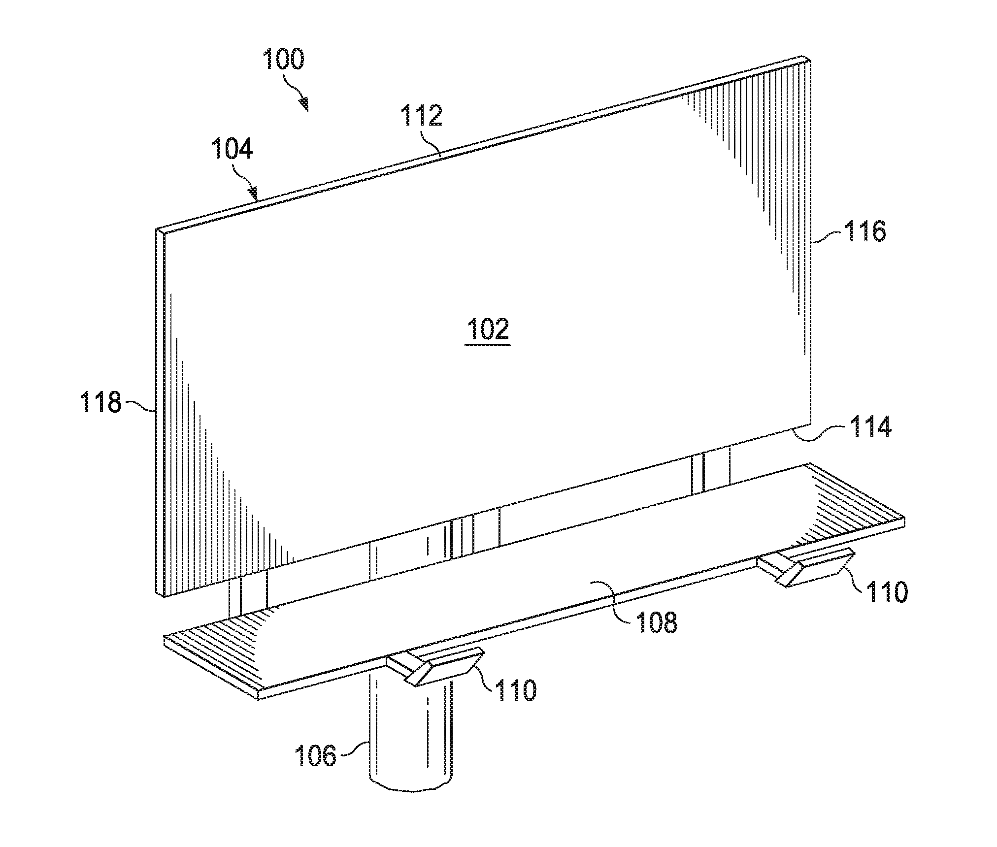
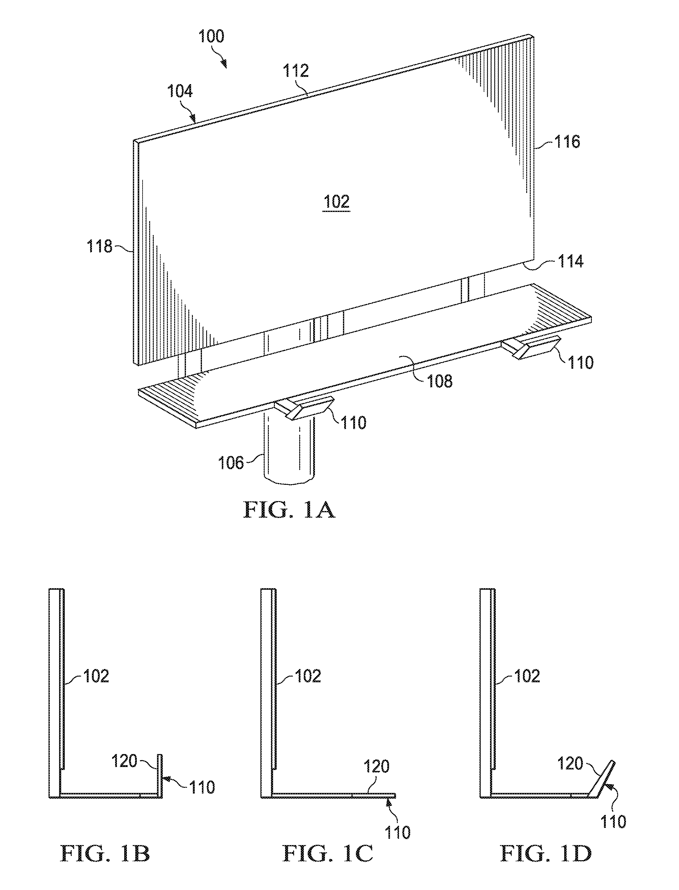
Referring to FIG. 1A, one embodiment of a billboard 100 is illustrated. The billboard 100 includes a surface 102 onto which a picture and/or text may be painted, mounted, or otherwise affixed. The surface 102 may be any size, such as a commonly used size having a width of forty-eight feet wide and a height of fourteen feet. The surface 102 may be provided by placing a backing material on a frame 104 made of steel and/or other materials. The frame 104 may be mounted on one or more support poles 106, which may be considered part of the frame 104 or separate from the frame 104. The billboard 100 may include a walkway or other support structure 108 that enables the surface 102 to be more easily accessed.
One or more lighting assemblies no may be coupled to the walkway 108 (e.g., to a safety rail or to the walkway itself) and/or to another structural member of the billboard 100 to illuminate some or all of the surface 102 in low light conditions. The lighting assembly no may be mounted at or near a top edge 112 of the billboard 100, a bottom edge 114 of the billboard 100, a right edge 116 of the billboard 100, and/or a bottom edge 118 of the billboard 100. The lighting assembly no may be centered (e.g., located in approximately the center of the billboard 100) or off center as illustrated in FIG. 1A.
With additional reference to FIGS. 1B-1D, a surface 120 of the lighting assembly no may be parallel with respect to the surface 102 of the billboard 100 (FIG. 1B), may be perpendicular with respect to the surface 102 (FIG. 1C), or may be angled with respect to the surface 102 (FIG. 1D). It is understood that the lighting assembly no may be placed in many different orientations and locations relative to the billboard 100 and to one another, and the illustrated positions are only for purposes of example. Furthermore, it is understood that references to "top," "bottom," "left," and "right" are used in the present disclosure for purposes of description and do not necessarily denote a fixed position. For example, the billboard 100 may be turned on end, and the referenced "top," "bottom," "left," and "right" edges may still be readily identifiable although the "top" edge would be the "left" edge or the "right" edge.
One problem with current lighting technology is that it can be difficult to direct light only onto the surface 102 and even more difficult to do so evenly. This may be due partly to the placement of the lighting assembly 110, as shown in FIGS. 1B-1D. As the lighting assembly 110 is off center relative to the surface 102, light emitted from the lighting assembly 110 may not evenly strike the surface 102. One problem with uneven illumination is that certain parts of the surface 102 may be more brightly illuminated than other parts. This creates "hot spots" that may be undesirable. Attempting to evenly illuminate the surface 102 may cause light to be directed past the edges 112, 114, 116, and 118 as attempts are made to balance out hot spots in particular areas. However, light that does not strike the surface 102 is wasted and may create problems (e.g., light pollution), as well as waste illumination that could be used for the surface 102.
In addition to the difficulties of evenly illuminating the surface 102, the use of LEDs in an exterior lighting environment involves issues such as heat dissipation and protecting the LEDs against environmental conditions such as moisture. The presence of moving mechanical features such as fans that may be used to provide increased airflow for cooling may create additional reliability problems. Due to the difficulty and expense of replacing and/or repairing the lighting assembly no in combination with the desire to provide consistent lighting while minimizing downtime, such issues should be addressed in a manner that enhances reliability and uptime.
Referring to FIG. 2, one embodiment of a lighting assembly 200 is illustrated. The lighting assembly 200 provides a more detailed embodiment of the lighting assembly 110 of FIG. 1. The lighting assembly 200 includes a back panel 202, a light panel 204 (e.g., a printed circuit board (PCB)) having a plurality of LEDs (not shown) mounted thereon, and an optics panel 206. As will be described below in more detailed examples, light from the LEDs of the light panel 204 may be directed by the optics panel 206 to illuminate the surface 102 of the billboard 100 of FIG. 1. The back panel 202 may be configured to serve as a supporting substrate for the light panel 204 and optics panel 206, as well as to dissipate heat produced by the LEDs.
It is understood that any of the back panel 202, light panel 204, and optics panel 206 may actually be two or more physical substrates rather than a single panel as illustrated in FIG. 2. Furthermore, it is understood that there may be additional panels positioned behind the back panel 202, in front of the optics panel 206, and/or between the back panel 202 and light panel 204 and/or between the light panel 204 and optics panel 206.
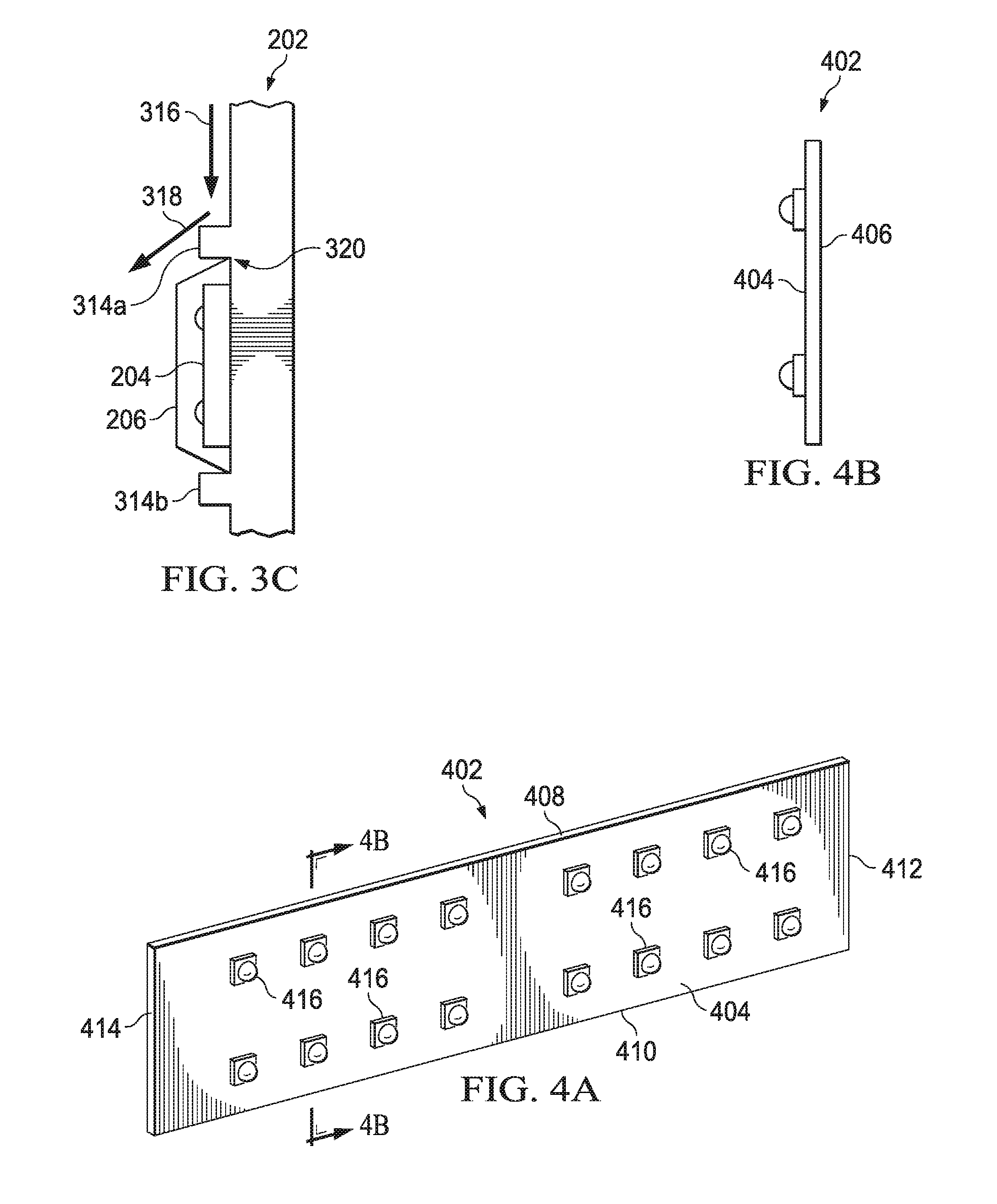
Referring to FIGS. 3A-3C, one embodiment of the back panel 202 is illustrated with a front surface 302 and a back surface 304. The back panel 202 includes a top edge 306, a bottom edge 308, a right edge 310, and a left edge 312. The panel 202 may be formed of one or more thermally conductive materials (e.g., aluminum) and/or other materials.
The front surface 302 provides a mounting surface for the light panel 204. In some embodiments, the front surface 302 of the panel 202 may include one or more protrusions 314a and 314b that are substantially parallel to the top edge 306. The protrusions 314a and 314b may be configured to protect the light panel 204 from moisture. Although only two protrusions 314a and 314b are illustrated, it is understood that a single protrusion may be provided or three or more protrusions may be provided. Furthermore, such protrusions may vary in length, shape (e.g., may have angled or curved surfaces), orientation, and/or location on the front surface 302.
Referring specifically to FIG. 3C, a light panel 204 and an optical panel 206 may be mounted under the protrusion 314a (FIG. 3C). Moisture running down the front surface 302 in the direction of arrow 316 may strike the protrusion 314a and be directed away from the light panel 204 and optical panel 206 as shown by arrow 318. Although not shown, moisture may also be directed length down the protrusion 314a. Accordingly, protrusion 314a may serve as a gutter and aid in directing moisture away from a joint 320 where the optical panel 206 abuts the front surface 302. This may be beneficial even when a moisture resistant compound is used to seal the joint 320. In embodiments where there are multiple light panels 204 arranged vertically on the front surface 302, there may be a protrusion positioned above each light panel 204. For example, the protrusion 314a may be positioned directly above one light panel 204 and the protrusion 314b may be positioned directly above another light panel 204.
Referring specifically to FIG. 3B, the back surface 304 may be configured to increase heat dissipation. For example, the back surface 304 may be configured with a heat sink provided by fins 322a-322N, where N denotes a total number of fins. The fins 322a-322N increase the surface area of the back surface 304, thereby providing for additional heat dissipation to the surrounding air. The fins 322a-322N may be formed as part of the panel 202 or may be otherwise coupled to the panel 202 (e.g., may be part of a discrete heat sink that is coupled to the back surface 304). Some or all of the fins 322a-322N may be angled, as shown by fins 322a and 322b. In some embodiments, holes (not shown) may be provided in some or all of the fins 322a-322N to aid in air circulation. In such embodiments, the holes may cause a chimney effect in which heated air rises through the holes and is replaced by cooler air. This may be particularly effective in environments where natural air movement is limited.
Referring to FIGS. 4A and 4B, one embodiment of a single PCB 402 of the light panel 204 is illustrated. In the present example, the light panel 204 may include multiple PCBs 402, although it is understood that any number of PCBs may be used based on design issues such as the amount of illumination needed, the amount of illumination provided by a single PCB 402, the size of the surface 102 of the billboard 100, and/or other factors. As shown in the present embodiment with a substantially rectangular cross-section, the PCB 402 includes a front surface 404, a back surface 406, a top edge 408, a bottom edge 410, a right edge 412, and a left edge 414.
The PCB 402 may include one or more strings of LEDs 416, with multiple LEDs 416 in a string. For example, a string may include eight LEDs 416 and each PCB 402 may include two strings for a total of sixteen LEDs 416. In this configuration, a light panel 204 having eight PCBs 402 would include ninety-six LEDs 416. It is understood that although the PCBs 402 are shown as being substantially identical, they may be different in terms of size, shape, and other factors for a single light panel 204.
In the present example, the LEDs 416 are surface mounted, but it is understood that the LEDs 416 may be coupled to the panel 204 using through hole or another coupling process. The surface mounted configuration may ensure that a maximum surface area of each LED 416 is in contact with the PCB 402, which is in turn in contact with the back panel 202 responsible for heat dissipation. Each string of LEDs may receive a constant current with the current divided evenly among the LEDs 416.
Referring to FIGS. 5A, 5B, 5C and 5D, one embodiment of a single lens panel 500 of the optics panel 206 is illustrated. In the present example, the optics panel 206 may include multiple lens panels 500, although it is understood that any number of lens panels may be used based on design issues such as the number, arrangement, and orientation of the LEDs 416, the size of the surface 102, and/or other factors. As shown in the present embodiment with a substantially rectangular cross-section that is configured for use with the PCB 402 of FIG. 4, a single lens panel 500 includes a front surface 502, a back surface 504, a top side 506, a bottom side 508, a right side 510, and a left side 512. The sides 506, 508, 510, and 512 may form a cavity into which the PCB 402 may fit, thereby providing protection for the PCB 402 from environmental conditions such as moisture.
The lens panel 500 may include a beveled or angled top side 506 and/or bottom side 508 as illustrated in FIG. 5B. The beveling/angling may aid in preventing moisture from reaching the PCB 402 under the lens panel 500, as water will more readily flow from the area of the joint 320 (FIG. 3C) due to the angled surface than if the top side 506 was relatively flat.
The lens panel 500 may include multiple optical elements 514. A single optical element 514 may be provided for each LED 416, a single optical element 514 may be provided for multiple LEDs 416, and/or multiple optical elements 514 may be provided for a single LED 416. In some embodiments, the optical elements 514 may be provided by a single multi-layer optical element system provided by the lens panel 500.
In the present example, the optical elements 514 are configured so that the light emitted from each LED 416 is projected onto the entire surface 102 of the billboard 100. In other words, if all other LEDs 416 were switched off except for a single LED 416, the entire surface 102 would be illuminated at the level of illumination provided by the single LED 416. In one embodiment, the rectangular target area of the surface 102 would be evenly illuminated by the LED 416, while areas beyond the edges 112, 114, 116, and 118 would receive no illumination at all or at least a minimal amount of illumination from the LED 416. What is meant by "evenly" is that the illumination with a uniformity that achieves a 3:1 ratio of the average illumination to the minimum. Thus, by designing the lens in such a manner, when all LEDs are operating, the light form the collective thereof will illuminate the surface at the 3:1 ratio. When one or more LEDs fail, the overall illumination decreases, but the uniformity maintains the same uniformity. Also, as described hereinabove, the "surface" refers to the surface that is associated with a particular LED panel. It may be that an overall illuminated surface is segmented and multiple panels are provided, each associated with a particular segment.
FIG. 5C illustrates a detail of the lens assembly. Each of the diodes 416 is mounted on the board 408 at a minimum distance. Overlying the board and LEDs 416 is transparent lens substrate 520. This substrate 520 has a plurality of lens structures 522, each associated with one of the LEDs 416, such that each of the LEDs 416 has the light emitted therefrom directed outward towards the surface, each lens structure being substantially the same. The minimum distance is designed such that overlapping light from adjacent LEDs does not create interference patterns and result in dead spots on the surface. The lens structure 522 is designed to create the 3:1 uniformity and also, the lens structure is designed to "direct" the light from an edge of the surface to cover the entire surface. This is shown by the angle of the light rays in FIG. 5C. Also, the beveled edge 530 will basically surround the PCB 402, thus protecting it from moisture. The lens substrate 520 is secured with screws (not shown).
FIG. 5D illustrates a detail of the lens structure 522. This structure includes an interior surface 524 and an exterior surface 526 that shapes and directs the light in the correct pattern. This is an acrylic material. With such a design, the lighting assembly can be disposed at an edge of the surface to illuminate the entire surface.
In some embodiments, as shown in FIG. 1, two lighting assemblies no may be used. Each lighting assembly may be powered by a separate power supply (not shown), and may be configured to illuminate the entire surface 102. In such an embodiment, if one power supply fails, the remaining lighting assembly no will still illuminate the entire surface 102, although at a lesser intensity than when both lighting assemblies 110 are functioning. This provides evenly distributed illumination when both lighting assemblies 110 are functioning correctly, and continues to provide evenly distributed illumination when one lighting assembly 110 malfunctions. Accordingly, the entire surface 102 of the billboard 100 may be illuminated even when an entire lighting assembly 110 has malfunctioned and is providing no illumination at all due to the redundancy provided by configuration of the lighting assemblies 110.
Furthermore, in some embodiments as described above, each LED 416 of a single lighting assembly no may be configured via the optical elements 514 to illuminate the entire surface 102. In such embodiments, if one or more LEDs 416 or strings of LEDs fails, the remaining LEDs 416 will still illuminate the entire surface 102, although at a lesser intensity than when the failed LEDs 416 are functioning. This provides evenly distributed illumination when all LEDs 416 are functioning correctly, and continues to provide evenly distributed illumination when one or more LEDs are malfunctioning. Accordingly, the billboard 100 may be illuminated even when multiple LEDs 416 have malfunctioned and are providing no illumination at all due to the redundancy provided by configuration of the lighting assemblies 110.
It is understood that some embodiments may direct substantially all illumination from a lighting assembly 110 evenly across the surface 102 while some illumination is not evenly distributed. For example, substantially all LEDs 416 may be directed to each evenly illuminate the surface 102 with the exception of a relatively small number of LEDs 416. In such cases, the illumination provided by the remaining LED or LEDs 416 may be directed to one or more portions of the surface 102. If done properly, this may be accomplished while minimizing any noticeable unevenness in the overall illumination, even if one of the remaining LEDs 416 malfunctions. For example, the lighting assembly 110 may be configured to direct the illumination provided by one LED 416 to only the left half of the surface 102, while directing the illumination from another LED 416 to only the right half of the surface 102. The loss of one of these two LEDs may not noticeably impact the illumination of the surface 102. It is understood that such variations are within the scope of this disclosure.
In embodiments where the illumination is evenly distributed across the surface 102, it is understood that the optics panel 206 may be configured specifically for the light panel 204 and the surface 102. For example, assuming the surface 102 is forty-eight feet wide and sixteen feet high, the lens panel 500 of FIG. 5 may be specifically designed for use with the PCB 402 of FIG. 4. This design may be based on the particular layout of the PCB 402 (e.g., the number and arrangement of the LEDs 416), the amount of illumination provided by the LEDs 416, the size of the surface 102, the distance between the lens panel 500 and the surface 102, the angle at which the lens panel 500 is mounted relative to the surface 102 (e.g., FIGS. 1B-1D), and/or other factors. Accordingly, changes in any of these factors may entail a change in the design of the lens panel 500 in order to again evenly distribute the illumination provided by each LED 416 across the entire surface 102. It is understood that various standard configurations of the lighting assembly 110 may be developed for various billboard and/or other externally illuminated signs so that a particular configuration may be provided based on the parameters associated with a particular billboard and/or externally illuminated sign.
Referring to FIGS. 6A-6C, one embodiment of a lighting assembly 600 is illustrated that provides a more detailed embodiment of the lighting assembly 200 of FIG. 2. The lighting assembly 600 includes a back panel 602, a light panel formed by multiple LED assemblies (denoted by reference number 800 in FIG. 8A), and an optics panel formed by multiple lens panels 604. Accordingly, as described previously, the light panel 204 in the current example is represented by multiple LED assemblies 800 and the optics panel 206 is represented by multiple lens panels 604. In the present embodiment, the lighting assembly 600 includes four LED assemblies 800 and four lens panels 604.
Although various attachment mechanisms (e.g., threaded screws, bolts, and/or other fasteners) may be used to coupled the lens panels and LED assemblies to the back panel 602, the present embodiment uses multiple threaded fasteners 605 (e.g., screws) that extend through the lens panels and the LED assemblies and engage threaded holes in the back panel 602.
The lighting assembly 600 is also illustrated with a mounting plate 606 that couples to the back panel 602 and to an adjustable mounting bracket 608. The adjustable mounting bracket 608 may be used to couple the lighting assembly 600 to a portion of the billboard 100 (FIG. 1) and/or to another support member. A power supply enclosure 610 may be coupled to the mounting plate 606 and configured contain a power supply (not shown) capable of supplying power to LEDs of the LED assemblies 800. It is noted that separating the power supply from the back panel 602 may aid in heat dissipation by the back panel 602 as it does not have to dissipate heat from the power supply to the same extent as if the power supply was mounted directly to the back panel 602.
The location of the power supply may also be beneficial as snow not melted by the heat produced by the LED may be melted by heat produced by the power supply. This may aid in reducing snow buildup on the LEDs.
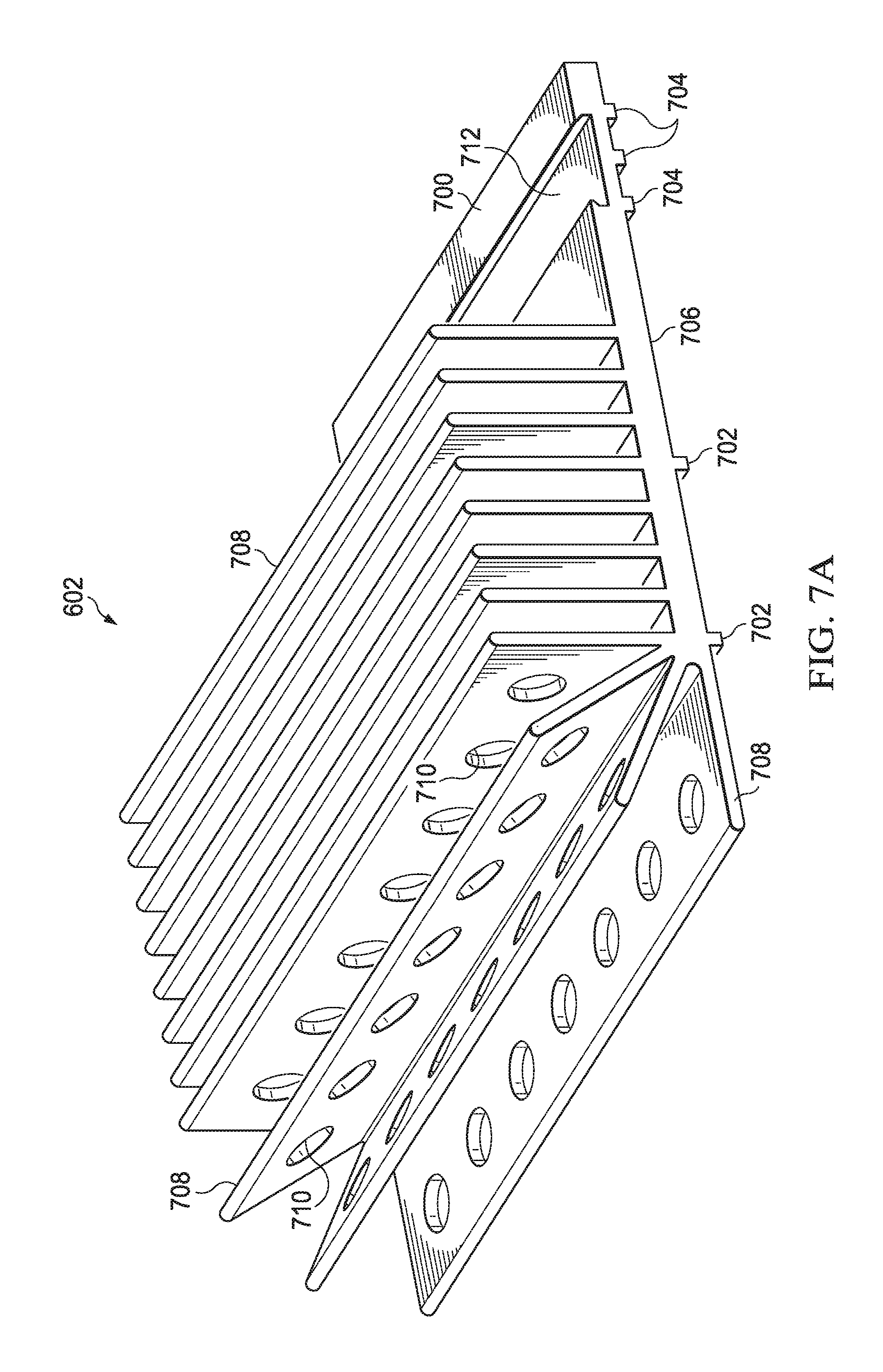
With additional reference to FIGS. 7A and 7B, one embodiment of the back panel of FIG. 602 is illustrated. A front surface 700 includes multiple protrusions 702 that may be configured to protect the light panels (not shown) against moisture as previously described. The front surface 700 may include additional protrusions 704.
A back surface 706 includes multiple fins 708 that form a heat sink to aid in the dissipation of heat from the back panel 602. In the present example, the fins 708 are substantially rectangular in shape. In the present example, the back panel 602 is extruded and the fins 708 run parallel to the top edge with a longitudinal axis of each fin 708 being substantially parallel to a longitudinal axis of the back panel 602. Forming the fins 708 in a vertical manner is possible, but may increase the cost of the back panel 602 due to the extrusion process. As shown, the fins 708 may be substantially perpendicular to the back surface 706, and/or may be angled. In the present example, the fins 708 are angled such that near the top of the back panel 702, the fins 708 are angled towards the top.
Because the fins 708 are parallel to the top edge, heat may be trapped due to its inability to rise vertically. Accordingly, holes 710 may be present in some or all of the fins 708 (marked but not actually visible in the side view of FIG. 7B) to provide paths for the heat to rise vertically in spite of the orientation of the fins 708. The holes 710 may create a chimney effect that increases air flow across the fins 708 and aids in the cooling process. In some embodiments, some or all of the fins 708 may be angled such that heat is not trapped.
The back surface 706 may also include a groove 712 that is configured to receive a tongue of the mounting plate 606 in a tongue-in-groove manner.
With additional reference to FIGS. 8A-8J, embodiments of a single LED assembly 800 and a single lens panel 604 that may be used with the lighting assembly 600 are illustrated. As shown, the single LED assembly 800 and the single optics panel 604 may be configured for use together.
Referring specifically to FIG. 8A, the LED assembly 800 includes a substrate 802 (e.g., a PCB) onto which are mounted multiple LEDs 804. In the present example, the LED assembly 800 includes two strings of eight LEDs 804 each for a total of sixteen LEDs 804. It is understood that this is merely an example, and there may be more or fewer LEDs 804 on the light panel 800, and the LEDs 804 may be arranged in many different ways on the substrate 802.
Referring also to FIGS. 8B-8J, the optics panel 604 may include optical elements 806 arranged on an upper surface 808 of the optics panel 604. The optics panel 604 may further include sides 810, 812, 814, and 816 that are configured to fit around the edge of the substrate 802 of the light panel 800. The bottom edge of each side 810, 812, 814, and 816 abuts the front surface 700 of the back panel 602 and may be sealed to the front surface 700 using a moisture resistant sealant.
As shown in FIGS. 8D-8H, a single optical element 806 may include multiple lens elements designed to distribute the illumination provided by a single LED 804 across a surface such as the surface 102 of FIG. 1. A first lens element 820 may be positioned proximate to the LED 804, and additional lens elements 822, 824, and 826 may be positioned above the lens element 820. Multiple optical elements 806 may be combined and formed as a single optics panel 604 that is configured to operate with the LED assembly 800.
Referring to FIG. 9, another embodiment of a lighting assembly 900 is illustrated that provides a more detailed embodiment of the lighting assembly 200 of FIG. 2. The lighting assembly 900 is similar to the lighting assembly 600 of FIG. 6, but includes six LED assemblies rather than the four six LED assemblies of the lighting assembly 600. It is understood that the lighting assembly 900 may require a larger power supply than the lighting assembly 600 (e.g., a one hundred and fifty watt power supply instead of a one hundred and twenty watt power supply).
Although the preferred embodiment has been described in detail, it should be understood that various changes, substitutions and alterations can be made therein without departing from the spirit and scope of the invention as defined by the appended claims.
* * * * *
References
D00000
D00001
D00002
D00003
D00004
D00005
D00006
D00007
D00008
D00009
D00010
D00011
D00012

D00013

XML
uspto.report is an independent third-party trademark research tool that is not affiliated, endorsed, or sponsored by the United States Patent and Trademark Office (USPTO) or any other governmental organization. The information provided by uspto.report is based on publicly available data at the time of writing and is intended for informational purposes only.
While we strive to provide accurate and up-to-date information, we do not guarantee the accuracy, completeness, reliability, or suitability of the information displayed on this site. The use of this site is at your own risk. Any reliance you place on such information is therefore strictly at your own risk.
All official trademark data, including owner information, should be verified by visiting the official USPTO website at www.uspto.gov. This site is not intended to replace professional legal advice and should not be used as a substitute for consulting with a legal professional who is knowledgeable about trademark law.