Clutch for a transmission
Heitzenrater , et al.
U.S. patent number 10,337,562 [Application Number 15/186,083] was granted by the patent office on 2019-07-02 for clutch for a transmission. This patent grant is currently assigned to GM GLOBAL TECHNOLOGY OPERATIONS LLC. The grantee listed for this patent is GM Global Technology Operations LLC. Invention is credited to Scott W. Heitzenrater, Russell D. Maki.

| United States Patent | 10,337,562 |
| Heitzenrater , et al. | July 2, 2019 |
Clutch for a transmission
Abstract
A torque transmitting device for an automotive transmission includes a clutch housing with a plurality of internal splines, a clutch hub with a plurality of external splines extending radially outwardly from the clutch hub, a plurality of friction plates with internal teeth and a first and a second surface. The first and second surface having a friction material disposed thereon and at least one of the internal teeth has an aperture and the plurality of internal teeth intermesh with the plurality of external splines on the outer surface of the clutch hub, a plurality of reaction plates having a plurality of external teeth and a first and a second surface. The plurality of external teeth intermesh with the plurality of internal splines in the clutch housing, and a spacer member disposed in the aperture separates a first of the friction plates from a second of the friction plates.
| Inventors: | Heitzenrater; Scott W. (Orion, MI), Maki; Russell D. (Canton, MI) | ||||||||||
|---|---|---|---|---|---|---|---|---|---|---|---|
| Applicant: |
|
||||||||||
| Assignee: | GM GLOBAL TECHNOLOGY OPERATIONS
LLC (Detroit, MI) |
||||||||||
| Family ID: | 60481202 | ||||||||||
| Appl. No.: | 15/186,083 | ||||||||||
| Filed: | June 17, 2016 |
Prior Publication Data
| Document Identifier | Publication Date | |
|---|---|---|
| US 20170363154 A1 | Dec 21, 2017 | |
| Current U.S. Class: | 1/1 |
| Current CPC Class: | F16D 13/683 (20130101); F16D 11/00 (20130101); F16D 21/00 (20130101); F16D 13/52 (20130101); F16D 13/646 (20130101); F16D 13/69 (20130101) |
| Current International Class: | F16D 11/00 (20060101); F16D 13/69 (20060101); F16D 21/00 (20060101); F16D 13/52 (20060101); F16D 13/64 (20060101); F16D 13/68 (20060101) |
References Cited [Referenced By]
U.S. Patent Documents
| 2855802 | October 1958 | Gorsky |
| 2995956 | August 1961 | Moore |
| 3584720 | June 1971 | Bark |
| 3735474 | May 1973 | Bark |
| 4252226 | February 1981 | Staub |
| 4291790 | September 1981 | Staub |
| 4396101 | August 1983 | Black |
| 4398436 | August 1983 | Fisher |
| 4573374 | March 1986 | Koshimo et al. |
| 4676121 | June 1987 | Kouno |
| 4800996 | January 1989 | Loizeau |
| 5551928 | September 1996 | Sudau |
| 5634866 | June 1997 | Sudau |
| 5713813 | February 1998 | von Greyerz |
| 5716300 | February 1998 | Sammataro et al. |
| 5733218 | March 1998 | Sudau et al. |
| 5735768 | April 1998 | Sudau |
| 5766109 | June 1998 | Sudau |
| 5816973 | October 1998 | Sudau et al. |
| 5836217 | November 1998 | Sudau et al. |
| 5863274 | January 1999 | Jackel |
| 5878856 | March 1999 | Sudau et al. |
| 5967939 | October 1999 | Reik et al. |
| 5976048 | November 1999 | Sudau et al. |
| 6003650 | December 1999 | Kleifges |
| 6019663 | February 2000 | Sudau |
| 6026944 | February 2000 | Satou |
| 6058801 | May 2000 | Schierling et al. |
| 6058802 | May 2000 | Sudau et al. |
| 6099434 | August 2000 | Sasse et al. |
| 6102174 | August 2000 | Sasse |
| 6126568 | October 2000 | Sudau |
| 6200222 | March 2001 | Sudau |
| 6230862 | May 2001 | Reik et al. |
| 6231472 | May 2001 | Sudau et al. |
| 6354974 | March 2002 | Kozarekar |
| 6398655 | June 2002 | Orlamunder et al. |
| 6435998 | August 2002 | Sudau et al. |
| 6439362 | August 2002 | Reik et al. |
| 6543596 | April 2003 | Martin |
| 6591705 | July 2003 | Reik et al. |
| 6695109 | February 2004 | Wack et al. |
| 6758315 | July 2004 | Bauer et al. |
| 6799665 | October 2004 | Sasse et al. |
| 6832672 | December 2004 | Bauer et al. |
| 6887180 | May 2005 | Pels et al. |
| 6962533 | November 2005 | Zottmann et al. |
| 7073646 | July 2006 | Sasse et al. |
| 7108626 | September 2006 | Friedmann |
| 7114565 | October 2006 | Man et al. |
| 7143879 | December 2006 | Ackermann et al. |
| 7261665 | August 2007 | Friedmann et al. |
| 7267212 | September 2007 | Wack et al. |
| 7287634 | October 2007 | Agner et al. |
| 7484607 | February 2009 | Schneider et al. |
| 7523817 | April 2009 | Forster |
| 7530223 | May 2009 | Ender et al. |
| 7604542 | October 2009 | Bach et al. |
| 7648009 | January 2010 | Wack et al. |
| 7651399 | January 2010 | Wack |
| 7662043 | February 2010 | Schmid et al. |
| 7743900 | June 2010 | Breier |
| 7993204 | August 2011 | Dogel |
| 8075410 | December 2011 | Carlson et al. |
| 8313385 | November 2012 | Mundt et al. |
| 8919518 | December 2014 | Diemer et al. |
| 8939270 | January 2015 | Dziurda |
| 2009/0314601 | December 2009 | Copeland |
| 2010/0216555 | August 2010 | Le Moal |
| 2011/0143843 | June 2011 | Yamamoto et al. |
| 2012/0228077 | September 2012 | DeGowske |
| 2013/0269475 | October 2013 | Le Moal |
| 2014/0162834 | June 2014 | Dogel et al. |
| 2015/0345569 | December 2015 | Erhard |
| 2018/0252273 | September 2018 | Friess |
| 3139658 | Apr 1983 | DE | |||
| 3423210 | Apr 1985 | DE | |||
| 3630398 | May 1987 | DE | |||
| 3612583 | Oct 1987 | DE | |||
| 3624496 | Jan 1988 | DE | |||
| 3624498 | Jan 1988 | DE | |||
| 3834284 | Apr 1990 | DE | |||
| 3926384 | Feb 1991 | DE | |||
| 3934798 | Apr 1991 | DE | |||
| 4121586 | Jan 1993 | DE | |||
| 4128868 | Mar 1993 | DE | |||
| 4333562 | Apr 1994 | DE | |||
| 4444196 | Jun 1995 | DE | |||
| 19514411 | Nov 1995 | DE | |||
| 0041708 | Dec 1981 | EP | |||
| 0086044 | Aug 1983 | EP | |||
| 0533426 | Mar 1993 | EP | |||
| 2782766 | Mar 2000 | FR | |||
| 2220464 | Oct 1990 | GB | |||
| 2285109 | Jun 1995 | GB | |||
| 2292596 | Feb 1996 | GB | |||
| 2320534 | Jun 1998 | GB | |||
| S602249 | Jan 1985 | JP | |||
| WO2006082455 | Aug 2006 | WO | |||
Claims
What is claimed is:
1. A torque transmitting device for an automotive transmission, the torque transmitting device comprising: a clutch housing having a plurality of internal splines extending radially inwardly from an interior surface of the clutch housing; a clutch hub having a plurality of external splines extending radially outwardly from an outer surface of the clutch hub; a plurality of friction plates having a plurality of internal teeth and a first and a second surface, wherein the first and the second surface has a friction material disposed thereon and wherein at least one of the plurality of internal teeth has an aperture and wherein the plurality of internal teeth intermesh with the plurality of external splines on the outer surface of the clutch hub; a plurality of reaction plates having a plurality of external teeth and a first and a second surface, and wherein the plurality of external teeth intermesh with the plurality of internal splines on the inner surface of the clutch housing; and a first spacer member disposed in and extending through the aperture of a first of the plurality of friction plates, the first spacer member contacting a second spacer member disposed in and extending through an aperture of a second of the plurality of friction plates, the first and the second spacer members separating the first of the plurality of friction plates from the second of the plurality of friction plates, wherein at least one of the plurality of external teeth of the plurality of reaction plates has an aperture, wherein the first spacer member and the second spacer member are resilient and each have a reduced cross-section portion configured to engage with the aperture, wherein the reduced cross-section portion is disposed between a first portion and a second portion, both the first and the second portions having a cross-section larger than the reduced cross-section portion.
2. The torque transmitting device of claim 1 wherein one or more of the first spacer member and the second spacer member is a rubber cylindrical member.
3. The torque transmitting device of claim 2 wherein the first spacer member and the second spacer member each further comprises a first helical spring portion connected to a rubber cylindrical portion and a second helical spring portion connected to the rubber cylindrical portion, the first helical spring portion disposed opposite the second helical spring portion.
4. The torque transmitting device of claim 1 wherein the first portion and the second portion are helical springs.
5. The torque transmitting device of claim 1 wherein a third spacer member is disposed in the aperture of the at least one of the plurality of external teeth of a first of the plurality of reaction plates, the third spacer member contacting a fourth spacer member disposed in an aperture of a second of the plurality of reaction plates, the third and fourth spacer members separating the first of the plurality of reaction plates from the second of the plurality of reaction plates.
6. The torque transmitting device of claim 1 wherein the aperture in at least one of the plurality of external teeth of the plurality of reaction plates is circular in shape.
7. The torque transmitting device of claim 6 wherein the first spacer member comprises one or more helical springs configured for engagement with the circular shape aperture in at least one of the plurality of external teeth of the plurality of reaction plates.
8. A torque transmitting device for an automotive transmission, the torque transmitting device comprising: a clutch housing having a plurality of internal splines extending radially inwardly from an interior surface of the clutch housing; a clutch hub having a plurality of external splines extending radially outwardly from an outer surface of the clutch hub; a plurality of friction plates having a plurality of internal teeth and a first and a second surface, wherein the first and second surface has a friction material disposed thereon and wherein at least one of the plurality of internal teeth has an aperture and wherein the plurality of internal teeth intermesh with the plurality of external splines on the outer surface of the clutch hub; a plurality of reaction plates having a plurality of external teeth and a first and a second surface, and wherein at least one of the plurality of external teeth has an aperture wherein the plurality of external teeth intermesh with the plurality of internal splines on the inner surface of the clutch housing; a first spacer member disposed in and extending through the aperture of a first of the plurality of internal teeth, the first spacer member contacting a second spacer member disposed in and extending through an aperture of a second of the plurality of internal teeth and separating a first of the plurality of friction plates from a second of the plurality of friction plates; and a third spacer member disposed in and extending through the aperture of a first of the plurality of external teeth, the third spacer member contacting a fourth spacer member disposed in and extending through an aperture of a second of the plurality of external teeth and separating a first of the plurality of reaction plates from a second of the plurality of reaction plates, wherein each of the third and fourth spacer members has a reduced cross-section portion configured for engagement with the aperture in at least one of the plurality of external teeth of the plurality of reaction plates and each of the first and second spacer members has a reduced cross-section portion configured for engagement with the aperture in at least one of the plurality of internal teeth of the plurality of friction plates, wherein the reduced cross-section portion of each of the first, second, third, and fourth spacer members is disposed between a first portion and a second portion, both the first and the second portions having a cross-section larger than the reduced cross-section portion.
9. The torque transmitting device of claim 8 wherein the first spacer member and the second spacer member further comprises a first helical spring portion connected to a rubber cylindrical portion and a second helical spring portion connected to the rubber cylindrical portion, the first helical spring portion disposed opposite the second helical spring portion.
10. The torque transmitting device of claim 8 wherein the first, second, third, and fourth spacer members are a first, a second, a third, and a fourth resilient member.
11. The torque transmitting device of claim 10 wherein the first, second, third, and fourth resilient members are rubber cylindrical members.
12. The torque transmitting device of claim 10 wherein the first, second, third, and fourth resilient members are a first, a second, a third, and a fourth helical spring.
13. The torque transmitting device of claim 12 wherein the third and the fourth helical springs are configured for engagement with a circular shaped aperture in at least one of the plurality of external teeth of the plurality of reaction plates and wherein the first and second helical springs are configured for engagement with a circular shaped aperture in at least one of the plurality of internal teeth of the plurality of friction plates.
14. The torque transmitting device of claim 8 wherein the aperture in at least one of the plurality of internal teeth of the plurality of friction plates is a slot.
15. The torque transmitting device of claim 8 wherein the aperture in at least one of the plurality of external teeth of the plurality of reaction plates is a slot.
16. The torque transmitting device of claim 8 wherein the aperture in at least one of the plurality of internal teeth of the plurality of friction plates is a circular shaped aperture.
17. The torque transmitting device of claim 8 wherein the aperture in at least one of the plurality of external teeth of the plurality of reaction plates is a circular shaped aperture.
Description
FIELD
The present invention relates generally to automotive transmissions having multiple plate clutches, and more particularly, to systems and devices for separating, and thereby reducing drag between relatively rotating plates of an automotive clutch.
BACKGROUND
The statements in this section merely provide background information related to the present disclosure and may or may not constitute prior art.
Clutches are employed for interruptably coupling two rotating components to one another, such as for example, an engine to a transmission. In multiple plate clutches, friction plates on a drive member rotate relative to interposed friction plates on another member when the clutch is disengaged. When the clutch is engaged, the multiple plates of the clutch are brought into physical contact, and the multiple plates frictionally engage with one another. When the clutch is disengaged, to reduce frictional drag between relatively rotating plates clutch plate separation devices, such as annular wave springs, may be disposed between the friction plates to effect plate separation.
While traditional multi-plate clutch separation mechanisms are effective, there is room in the art for an improved multi-plate clutch separation mechanism that ensures rapid clutch plate separation without additional rotating mass or substantial cost. Especially desirable, would be a multi-plate clutch separation mechanism that can be fitted to currently-available transmissions as well as future transmissions.
SUMMARY
In one embodiment of the present invention, a torque transmitting device for an automotive transmission includes, a clutch housing having a plurality of internal splines extending radially inwardly from an interior surface of the clutch housing, a clutch hub having a plurality of external splines extending radially outwardly from an outer surface of the clutch hub, a plurality of friction plates having a plurality of internal teeth and a first and a second surface, wherein the first and second surface has a friction material disposed thereon and wherein at least one of the plurality of internal teeth has an aperture and wherein the plurality of internal teeth intermesh with the plurality of external splines on the outer surface of the clutch hub, a plurality of reaction plates having a plurality of external teeth and a first and a second surface, and wherein the plurality of external teeth intermesh with the plurality of internal splines on the inner surface of the clutch housing. The torque transmitting device for an automotive transmission also includes a spacer member disposed in the aperture for separating a first of the plurality of friction plates from a second of the plurality of friction plates.
In another embodiment of the present invention, the spacer member is a resilient member.
In yet another embodiment of the present invention, the resilient member is a rubber cylindrical member.
In yet another embodiment of the present invention, the resilient member is a helical spring.
In yet another embodiment of the present invention, at least one of the plurality of external teeth of the plurality of reaction plates has an aperture.
In yet another embodiment of the present invention, a spacer member is disposed in the aperture of the at least one of the plurality of external teeth of the plurality of reaction plates for separating a first of the plurality of reaction plates from a second of the plurality of reaction plates.
In yet another embodiment of the present invention, the aperture in at least one of the plurality of external teeth of the plurality of reaction plates is a slot.
In yet another embodiment of the present invention, the rubber cylindrical member has a reduced cross-section portion configure for engagement with the slot in at least one of the plurality of external teeth of the plurality of reaction plates.
In yet another embodiment of the present invention, the aperture in at least one of the plurality of external teeth of the plurality of reaction plates is circular in shape.
In yet another embodiment of the present invention, the helical spring is configured for engagement with the circular shape aperture in at least one of the plurality of external teeth of the plurality of reaction plates.
In still another embodiment of the present invention, a torque transmitting device for an automotive transmission includes, a clutch housing having a plurality of internal splines extending radially inwardly from an interior surface of the clutch housing, a clutch hub having a plurality of external splines extending radially outwardly from an outer surface of the clutch hub, a plurality of friction plates having a plurality of internal teeth and a first and a second surface, wherein the first and second surface has a friction material disposed thereon and wherein at least one of the plurality of internal teeth has an aperture and wherein the plurality of internal teeth intermesh with the plurality of external splines on the outer surface of the clutch hub, a plurality of reaction plates having a plurality of external teeth and a first and a second surface, and wherein at least one of the plurality of external teeth has an aperture wherein the plurality of external teeth intermesh with the plurality of internal splines on the inner surface of the clutch housing, a first spacer member disposed in the aperture of the at least one of the plurality of internal teeth for separating a first of the plurality of friction plates from a second of the plurality of friction plates. The torque transmitting device for an automotive transmission also includes a second spacer member disposed in the aperture of the at least one of the plurality of external teeth for separating a first of the plurality of reaction plates from a second of the plurality of friction plates.
In yet another embodiment of the present invention, the first and second spacer members are a first and a second resilient member.
In yet another embodiment of the present invention, the first and the second resilient member are rubber cylindrical members.
In yet another embodiment of the present invention, the first and the second resilient member is a first and a second helical spring.
In yet another embodiment of the present invention, the aperture in at least one of the plurality of internal teeth of the plurality of friction plates is a slot.
In yet another embodiment of the present invention, the aperture in at least one of the plurality of external teeth of the plurality of reaction plates is a slot.
In yet another embodiment of the present invention, the aperture in at least one of the plurality of internal teeth of the plurality of friction plates is a circular shaped aperture.
In yet another embodiment of the present invention, the aperture in at least one of the plurality of external teeth of the plurality of reaction plates is a circular shaped aperture.
In yet another embodiment of the present invention, the rubber cylindrical member has a reduced cross-section portion configured for engagement with the slot in at least one of the plurality of external teeth of the plurality of reaction plates and the slot in at least one of the plurality of internal teeth of the plurality of friction plates.
In yet another embodiment of the present invention, the first and second helical springs are configured for engagement with the circular shaped aperture in at least one of the plurality of external teeth of the plurality of reaction plates and the circular shaped aperture in at least one of the plurality of internal teeth of the plurality of friction plates.
BRIEF DESCRIPTION OF THE DRAWINGS
The drawings described herein are for illustration purposes only and are not intended to limit the scope of the present disclosure in any way. The components in the figures are not necessarily to scale, emphasis instead being placed upon illustrating the principles of the invention. Moreover, in the figures, like reference numerals designate corresponding parts throughout the views. In the drawings:
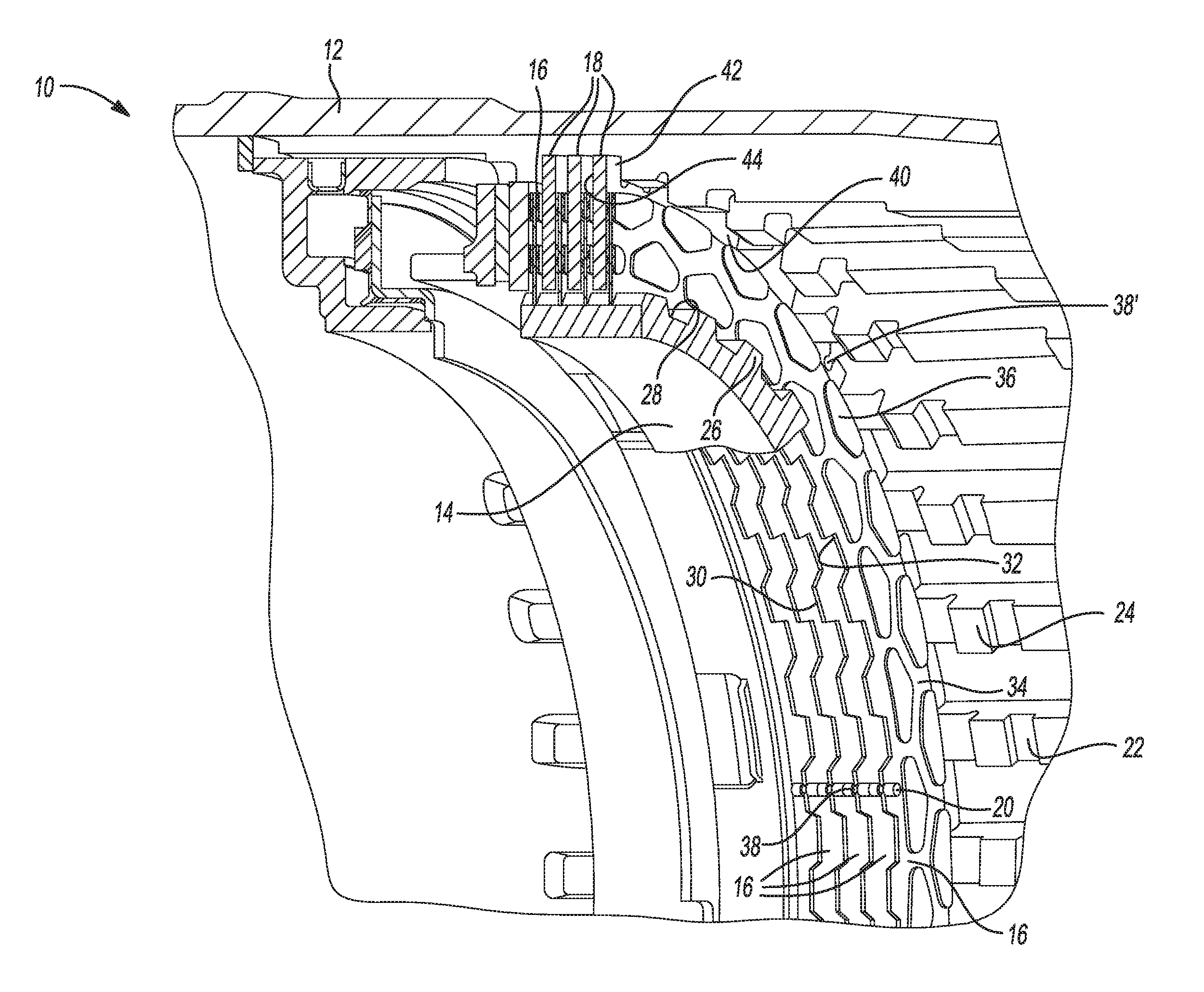
FIG. 1 is a perspective cross-sectional view of a torque transmitting device for an automotive transmission, according to the principles of the present invention;
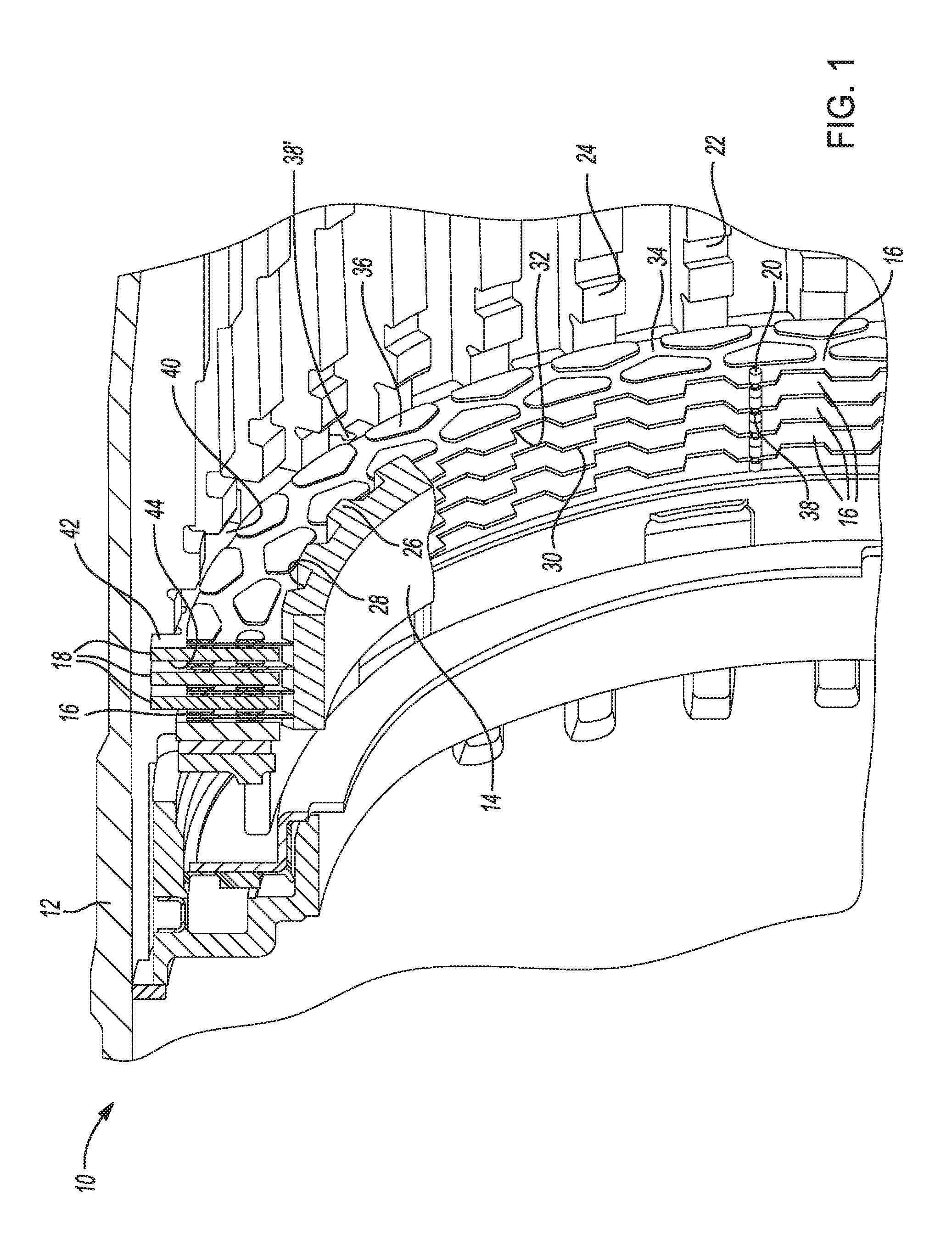
FIG. 2a is a perspective view of a spacer member of a torque transmitting device for an automotive transmission, according to the principles of the present invention;
FIG. 2b is a plan view of a helical spring spacer member with a reduced cross sectional portion for a torque transmitting device for an automotive transmission, according to the principles of the present invention;
FIG. 2c is a plan view of a helical spring spacer member having a base component for a torque transmitting device for an automotive transmission, according to the principles of the present invention;
FIG. 2d is a plan view of a helical spring spacer member of a torque transmitting device for an automotive transmission, according to the principles of the present invention;
FIG. 3a is a perspective view of a reaction plate of a torque transmitting device for an automotive transmission, according to the principles of the present invention;
FIG. 3b is a perspective view of a portion of a reaction plate of a torque transmitting device for an automotive transmission, according to the principles of the present invention;
FIG. 3c is a plan view of a portion of a reaction plate of a torque transmitting device for an automotive transmission, according to the principles of the present invention;
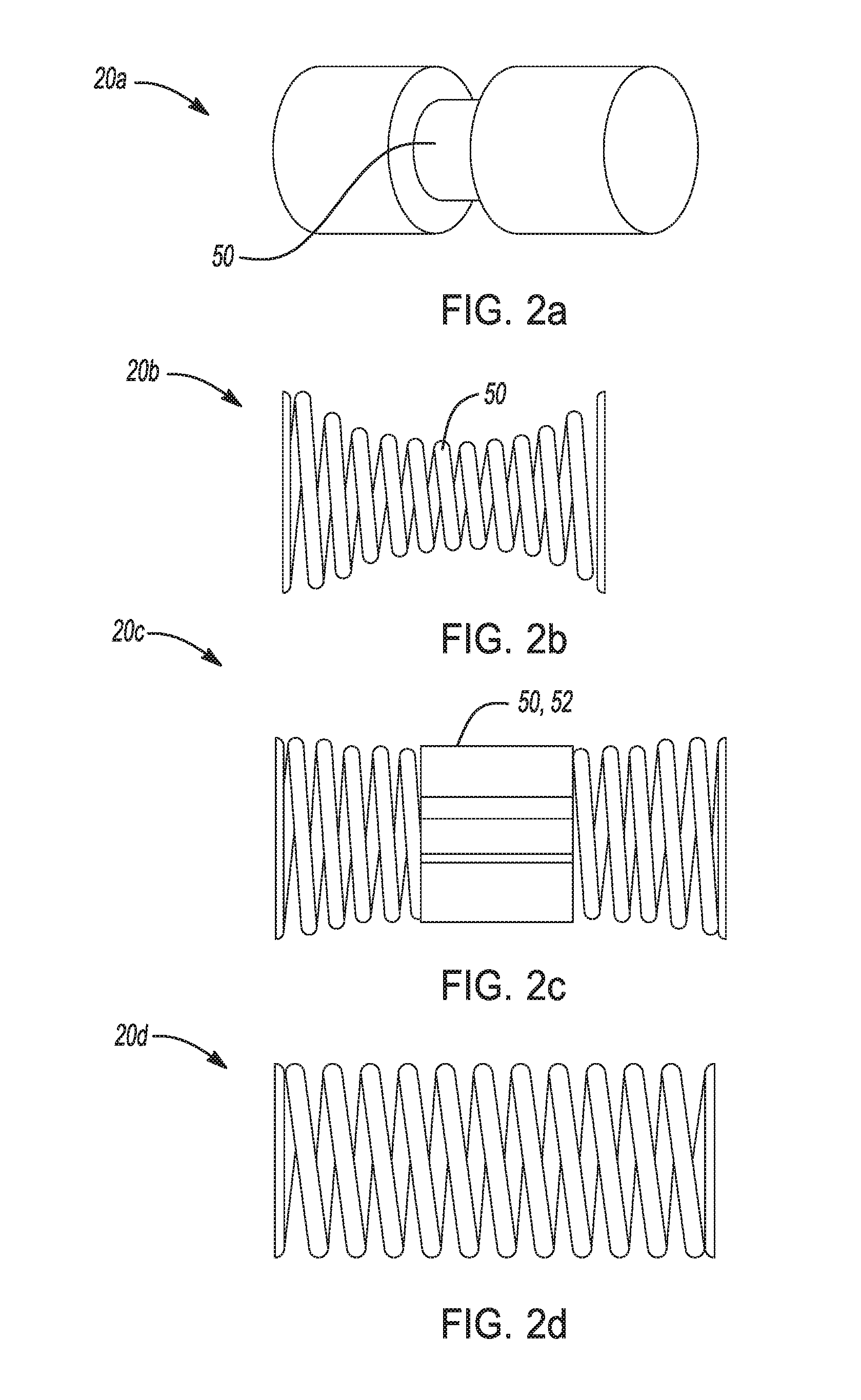
FIG. 4a is a perspective view of a friction plate of a torque transmitting device for an automotive transmission, according to the principles of the present invention; and
FIG. 4b is a perspective view of a portion of a friction plate of a torque transmitting device for an automotive transmission, according to the principles of the present invention.
DETAILED DESCRIPTION
The following description is merely exemplary in nature and is not intended to limit the present disclosure, application, or uses.
Referring now to FIGS. 1 and 2a-d a torque transmitting device 10 for an automotive transmission is shown. The torque transmitting device 10 includes a clutch housing 12, a clutch hub 14, a plurality of friction plates 16, a plurality of reaction plates 18, and spacer members 20.
The clutch housing 12 has a plurality of internal splines 22 which extend radially inwardly from an interior surface 24 of the clutch housing 12. The clutch hub 14 has a plurality of external splines 26 extending radially outwardly from an outer surface 28 of the clutch hub. Each of the plurality of friction plates 16 is disposed within the clutch housing 12 and has a plurality of internal teeth 30 and a first 32 and a second surface 34. A friction material 36 is disposed on the first surface 32 and the second surface 34 of the plurality of friction plates 16. The plurality of internal teeth 30 also intermesh with the plurality of external splines 26 on the outer surface 28 of the clutch hub 14. Additionally, at least one of the plurality of internal teeth 30 of the plurality of friction plates 16 has an aperture 38. The aperture 38 is formed through at least one of the internal teeth 30 of the plurality of friction plates 16.
Each of the plurality of reaction plates 18 has a plurality of external teeth 40 and a first 42 and a second surface 44. The plurality of external teeth 40 of the reaction plates 18 intermesh with the plurality of internal splines 22 on the inner surface 24 of the clutch housing 12. At least one of the plurality of external teeth 40 of the plurality of reaction plates 18 has an aperture 38'. The aperture 38' is formed through at least one of the external teeth 40 of the plurality of reaction plates 18.
In an example, the plurality of friction plates 16 is alternatingly disposed with the plurality of reaction plates 18. That is, the plurality of friction plates 16 are generally disposed adjacent to at least one of the plurality of reaction plates 18 such that the first surface 32 of a friction plate 16 is adjacent to the first surface 42 of a reaction plate and the second surface 34 of a friction plate 16 is adjacent to the second surface 44 of a reaction plate. With further reference to the example above, in the configuration described, the friction material 36 on the first and second surfaces 32, 34 of the plurality of friction plates 16 is placed in contact with the first and second surfaces 42, 44 of the plurality of reaction plates when the clutch is engaged.
In one aspect of the present invention, the spacer members 20 are disposed in the aperture 38 of the internal teeth 30 of at least one of the plurality of friction plates 16, and separate a first of the plurality of friction plates 16 from a second of the plurality of friction plates 16. In another aspect, the spacer members 20 are disposed in the aperture 38' of at least one of the plurality of external teeth 40 of the plurality of reaction plates 18. The spacer members 20 separate a first of the plurality of reaction plates 18 from a second of the plurality of reaction plates 18. Moreover, in one aspect of the present invention, the spacer members 20 are disposed in the apertures 38, 38' of at least one of the plurality of friction plates 16 and at least one of the plurality of reaction plates 18, and the spacer members 20 axially separate the plurality of friction plates 16 from the plurality of reaction plates 18.
Referring now to FIGS. 2a-d, and 3a-c, the apertures 38, 38' are configured to receive the spacer members 20, and may take a variety of forms including but not limited to slots 46 and circular openings 48. The spacer members 20 are disposed in the aperture 38, 38' of at least one of the plurality of friction plates 16 and/or at least one of the plurality of reaction plates 18. The spacer members 20 may be any resilient members, such as a rubber cylindrical members 20a, or a helical springs 20b-d. In one aspect, the spacer members 20 may be rubber cylindrical members 20a having a reduced cross-sectional portion 50 configured to engage with the slot 46 or circular aperture 48 in at least one of the plurality of external teeth 40 of the plurality of reaction plates 18, or in at least one of the plurality of internal teeth 30 of the plurality of friction plates 16. In an aspect, the spacer members 20 may be helical springs 20b-d having a base component 52, such as the base component 52 of helical spring 20c, configured for engagement with the slot 46 or circular aperture 48 in at least one of the plurality of external teeth 40 of the plurality of reaction plates 18, or in at least one of the plurality of internal teeth 30 of the plurality of friction plates 16.
Turning again to FIGS. 1 and 2a-d, and with additional reference to FIGS. 3a-c, 4a, and 4b, the spacer members 20 are disposed in the apertures 38 of at least one of the plurality of internal teeth 30 of the plurality of friction plates 16 or in the aperture 38' of at least one of the plurality of external teeth 40 of the plurality of reaction plates 18. With the spacer members 20 disposed in at least one of the plurality of internal teeth 30, a first of the plurality of friction plates 16 may be separated from a second of the plurality of friction plates 16. With the spacer members 20 disposed in at least one of the plurality of external teeth 40, a first of the plurality of reaction plates 18 may be separated from a second of the plurality of reaction plates 18. Furthermore, with the spacer members 20 disposed in at least one of the plurality of internal teeth 30 of a first of the plurality of friction plates 16, or within at least one of the plurality of external teeth 40 of a first of the plurality of reaction plates 18, the first of the friction plates 16 may be separated from the first of the reaction plates 18.
With particular reference to FIG. 3a, an exemplary reaction plate 18 having a plurality of spacer members 20 is shown. The spacer members 20 are disposed within exemplary apertures 38' of the plurality of external teeth 40 of the reaction plates 18. In the portions of the exemplary reaction plates of FIGS. 3b and 3c, exemplary apertures 38' are shown. In FIG. 3b, a circular aperture 48 is displayed, and in FIG. 3c, a slot 46 aperture 38' is shown.
Similarly, in the views of FIGS. 4a and 4b, an exemplary friction plate 16 has a plurality of spacer members 20 disposed within a plurality of internal teeth 30 of the friction plate 16. Moreover, in an aspect, the exemplary apertures 38 are slots 46 configured to receive the spacer members 20.
Because the apertures 38, 38' of the friction plates 16 and the reaction plates 18 are voids, the relative masses of the friction plates 16 and reaction plates 18 are reduced. However, the mass reduction of the apertures 38, 38' is negated by the addition of the spacer members 20. Thus, in an aspect, the addition of spacer members 20 is mass-neutral. Additionally, the spacer members 20 perform a mechanical function, rapidly separating the friction plates 16 and the reaction plates 18 from each other when the torque transmitting device 10 is disengaged. The rapid separation of the friction plates 16 and reaction plates 18 reduces frictional wear to the friction plates 16 and reaction plates 18, thereby prolonging the lifespan of the torque transmitting device 10.
The broad teachings of the disclosure can be implemented in a variety of forms. Therefore, while this disclosure includes particular examples, the true scope of the disclosure should not be so limited since other modifications will become apparent to the skilled practitioner upon a study of the drawings, the specification, and the following claims.
* * * * *
D00000
D00001
D00002
D00003
D00004
XML
uspto.report is an independent third-party trademark research tool that is not affiliated, endorsed, or sponsored by the United States Patent and Trademark Office (USPTO) or any other governmental organization. The information provided by uspto.report is based on publicly available data at the time of writing and is intended for informational purposes only.
While we strive to provide accurate and up-to-date information, we do not guarantee the accuracy, completeness, reliability, or suitability of the information displayed on this site. The use of this site is at your own risk. Any reliance you place on such information is therefore strictly at your own risk.
All official trademark data, including owner information, should be verified by visiting the official USPTO website at www.uspto.gov. This site is not intended to replace professional legal advice and should not be used as a substitute for consulting with a legal professional who is knowledgeable about trademark law.