Steam turbine preheating system with a steam generator
Mathai , et al.
U.S. patent number 10,337,357 [Application Number 15/420,776] was granted by the patent office on 2019-07-02 for steam turbine preheating system with a steam generator. This patent grant is currently assigned to General Electric Company. The grantee listed for this patent is General Electric Company. Invention is credited to Sanji Ekanayake, William Theadore Fisher, Joseph Philip Klosinski, George Vargese Mathai, Alston Ilford Scipio.


| United States Patent | 10,337,357 |
| Mathai , et al. | July 2, 2019 |
Steam turbine preheating system with a steam generator
Abstract
The present application provides a power generation system. The power generation system may include a gas turbine engine, a steam turbine, and a steam turbine preheating system. The steam turbine preheating system may include a steam generator that creates a flow of steam to preheat the steam turbine from an extraction of the gas turbine engine.
| Inventors: | Mathai; George Vargese (Atlanta, GA), Klosinski; Joseph Philip (Kennesaw, GA), Ekanayake; Sanji (Mableton, GA), Scipio; Alston Ilford (Mableton, GA), Fisher; William Theadore (Atlanta, GA) | ||||||||||
|---|---|---|---|---|---|---|---|---|---|---|---|
| Applicant: |
|
||||||||||
| Assignee: | General Electric Company
(Schenectady, NY) |
||||||||||
| Family ID: | 61005730 | ||||||||||
| Appl. No.: | 15/420,776 | ||||||||||
| Filed: | January 31, 2017 |
Prior Publication Data
| Document Identifier | Publication Date | |
|---|---|---|
| US 20180216499 A1 | Aug 2, 2018 | |
| Current U.S. Class: | 1/1 |
| Current CPC Class: | F01K 23/10 (20130101); F02C 6/06 (20130101); F01K 13/003 (20130101); F01K 17/025 (20130101); F02C 6/18 (20130101); F01D 25/10 (20130101); F01K 13/025 (20130101); Y02E 20/16 (20130101); F05D 2220/72 (20130101); Y02E 20/14 (20130101) |
| Current International Class: | F02C 6/06 (20060101); F02C 6/18 (20060101); F01D 25/10 (20060101); F01K 23/10 (20060101); F01K 17/02 (20060101); F01K 13/02 (20060101); F01K 13/00 (20060101) |
| Field of Search: | ;290/52 ;60/39.182,652,772,773,775 |
References Cited [Referenced By]
U.S. Patent Documents
| 2247845 | June 1939 | Meyer |
| 2470729 | May 1947 | Stalker |
| 3448580 | June 1969 | Nettel |
| 3448581 | June 1969 | Nettel |
| 3992876 | November 1976 | Aguet |
| 4250704 | February 1981 | Bruckner et al. |
| 4465027 | August 1984 | Steinegger |
| 4584836 | April 1986 | McClelland |
| 4831817 | May 1989 | Linhardt |
| 4896499 | January 1990 | Rice |
| 5042246 | August 1991 | Moore |
| 5132007 | July 1992 | Meyer et al. |
| 5203160 | April 1993 | Ozono |
| 5269130 | December 1993 | Finckh et al. |
| 5365730 | November 1994 | Bruckner et al. |
| 5412936 | May 1995 | Lee |
| 5473898 | December 1995 | Briesch |
| 5617715 | April 1997 | Beer et al. |
| 5887418 | March 1999 | Bruckner et al. |
| 6065280 | May 2000 | Ranasinghe et al. |
| 6085514 | July 2000 | Benim |
| 6244033 | June 2001 | Wylie |
| 6519927 | February 2003 | Liebig |
| 6598399 | July 2003 | Liebig |
| 6874322 | April 2005 | Schwarzott |
| 6983585 | January 2006 | Hattori et al. |
| 7367192 | May 2008 | Hattori et al. |
| 7961835 | June 2011 | Keller |
| 8484975 | July 2013 | West |
| 8505309 | August 2013 | Gardiner et al. |
| 8955322 | February 2015 | Bronicki et al. |
| 9046037 | June 2015 | Broesamle et al. |
| 9217566 | December 2015 | Bloch |
| 9222410 | December 2015 | Chillar et al. |
| 9341113 | May 2016 | John et al. |
| 9404393 | August 2016 | Pang et al. |
| 9708973 | July 2017 | Wall et al. |
| 9890665 | February 2018 | Carroni |
| 2001/0015062 | August 2001 | Fischer |
| 2005/0150229 | July 2005 | Baer et al. |
| 2005/0268594 | December 2005 | Kurihara |
| 2006/0254280 | November 2006 | Briesch |
| 2008/0236616 | October 2008 | Bloch |
| 2009/0241551 | October 2009 | Grover |
| 2010/0064855 | March 2010 | Lanyi et al. |
| 2010/0146982 | June 2010 | Lanyi et al. |
| 2010/0199631 | August 2010 | Vilimec |
| 2012/0031101 | February 2012 | Hoffmann et al. |
| 2012/0227372 | September 2012 | Li |
| 2012/0260667 | October 2012 | Chillar et al. |
| 2012/0317988 | December 2012 | Gardiner et al. |
| 2013/0125557 | May 2013 | Scipio |
| 2013/0160424 | June 2013 | Broesamle et al. |
| 2013/0178677 | July 2013 | Schmid et al. |
| 2013/0327051 | December 2013 | Carroni |
| 2014/0109844 | April 2014 | Wall et al. |
| 2014/0110092 | April 2014 | John et al. |
| 2014/0116063 | May 2014 | Deng |
| 2014/0174477 | June 2014 | Bloch |
| 2014/0174559 | June 2014 | Bloch |
| 2014/0230862 | August 2014 | Bloch |
| 2014/0237839 | August 2014 | Bloch |
| 2014/0238507 | August 2014 | Bloch |
| 2015/0136046 | May 2015 | Millner et al. |
| 2015/0345390 | December 2015 | Ekanayake |
| 2015/0345393 | December 2015 | Ekanayake |
| 2015/0345401 | December 2015 | Ekanayake |
| 2016/0040596 | February 2016 | Klosinski |
| 2016/0123190 | May 2016 | Klosinski |
| 2016/0258327 | September 2016 | Klosinski |
| 2016/0273408 | September 2016 | Ekanayake |
| 2016/0290214 | October 2016 | Ekanayake |
| 2016/0290232 | October 2016 | Ekanayake |
| 2016/0290235 | October 2016 | Ekanayake |
| 2016/0326960 | November 2016 | Baladi et al. |
| 2017/0254225 | September 2017 | Kim et al. |
| 2018/0058334 | March 2018 | Mathai et al. |
| 2018/0073440 | March 2018 | Mathai et al. |
| 2018/0100442 | April 2018 | Mathai et al. |
| 2018/0119577 | May 2018 | Zhang et al. |
| 2018/0216497 | August 2018 | Klosinski |
| 2018/0216499 | August 2018 | Mathai et al. |
| 2018/0274391 | September 2018 | Mathai et al. |
| 2018/0298816 | October 2018 | Conde |
| 0083109 | Jul 1983 | EP | |||
| 0537307 | Apr 1993 | EP | |||
| 0605156 | Jul 1994 | EP | |||
| 2738360 | Jun 2014 | EP | |||
| S5993907 | May 1984 | JP | |||
Other References
|
Search Report, EP 18152057.8, dated Jun. 19, 2018 (9 pp.). cited by applicant . Search Report, EP 18152078.4, dated Jun. 28, 2018 (1 p.). cited by applicant. |
Primary Examiner: Cuevas; Pedro J
Attorney, Agent or Firm: Eversheds Sutherland (US) LLP
Claims
We claim:
1. A power generation system, comprising: a gas turbine engine; a steam turbine; and a steam turbine preheating system; wherein the steam turbine preheating system comprises a steam generator that creates a flow of steam to preheat the steam turbine from an extraction of the gas turbine engine.
2. The power generation system of claim 1, wherein the gas turbine engine comprises a turbine casing and wherein the extraction extends from the turbine casing to the steam generator.
3. The power generation system of claim 1, wherein the extraction comprises an extraction of hot combustion gases.
4. The power generation system of claim 1, wherein the steam generator comprises a source of feedwater in communication therewith.
5. The power generation system of claim 1, wherein the steam turbine comprises a steam turbine shell and wherein the flow of steam extends from the steam generator to the steam turbine shell.
6. The power generation system of claim 1, further comprising a controller in communication with a plurality of sensors.
7. The power generation system of claim 1, further comprising a heat recovery steam generator.
8. The power generation system of claim 1, wherein the steam turbine preheating system comprises an attemperation system.
9. The power generation system of claim 8, wherein the attemperation system comprises a spray system for at least one of a water injection and a steam injection.
10. The power generation system of claim 1, wherein the steam turbine preheating system comprises an ejector in communication with the steam generator.
11. The power generation system of claim 10, wherein the ejector is in communication with at least one of an ambient air flow, a filtered air flow, and a compressor air extraction.
12. The power generation system of claim 1, wherein the steam turbine preheating system comprises a cascading ejector system in communication with the steam generator.
13. The power generation system of claim 12, wherein the cascading ejector system comprises a first ejector in communication with a compressor of the gas turbine engine and a second ejector in communication with a turbine of the gas turbine engine.
14. The power generation system of claim 1, wherein the steam turbine preheating system comprises a further extraction from downstream of the gas turbine engine to the steam generator.
15. A method of preheating a steam turbine in a power generation system, comprising: extracting hot combustion gases from a gas turbine to a steam generator; flowing feedwater to the steam generator; exchanging heat between the hot combustion gases and the flow of feedwater to create a flow of steam in the steam generator; and flowing the steam to the steam turbine to warm a shell of the steam turbine.
16. A combined cycle power generation system, comprising: a gas turbine engine; a steam turbine; a heat recovery steam generator; and a steam turbine preheating system; wherein the steam turbine preheating system comprises a steam generator that creates a flow of steam to preheat the steam turbine from an extraction of the gas turbine engine and a flow of feedwater.
17. The combined cycle power generation system of claim 16, wherein the gas turbine engine comprises a turbine casing and wherein the extraction extends from the turbine casing to the steam generator.
18. The combined cycle power generation system of claim 16, wherein the extraction comprises an extraction of hot combustion gases.
19. The combined cycle power generation system of claim 16, wherein the steam turbine comprises a steam turbine shell and wherein the flow of steam extends from the steam generator to the steam turbine shell.
20. The combined cycle power generation system of claim 16, wherein the steam turbine preheating system comprises a spray system for at least one of a water injection and a steam injection.
Description
TECHNICAL FIELD
The present application and the resultant patent relate generally to turbomachinery and more particularly relate to a power generation system with a steam turbine having a preheating system for using hot combustion gas extractions from a gas turbine to create a flow of steam in a steam generator to warm the steam turbine during start-up.
BACKGROUND OF THE INVENTION
A power generation plant such as a combined cycle power generation system generally includes a gas turbine engine, a heat recovery steam generator, and a steam turbine. The gas turbine engine may be coupled with a generator to produce electricity or to drive other types of loads. The hot combustion gases from the gas turbine engine may be introduced into the heat recovery steam generator to generate a flow of steam. The flow of steam in turn may drive the steam turbine. The steam turbine also may be coupled to a generator to produce additional electricity. A co-generation power generation system and the like may operate in a similar manner to produce both electricity and heat.
Minimizing start-up times may improve the availability of the combined cycle power plant and may reduce overall maintenance costs and start-up emissions. Steam turbine start-up, however, may be slow relative to gas turbine start-up. The start-up time of the steam turbine may be limited by thermal stresses caused by temperature gradients between, for example, the rotor core and the blades. As the rotor temperature is increased, higher inlet steam temperatures may be allowed. Gas turbine output, however, may not be allowed to increase until the steam turbine and the internal rotor are heated to a sufficient temperature. Running the gas turbine at such a low output may reduce the overall power generation, may waste fuel, and may cause higher concentrations of emissions.
SUMMARY OF THE INVENTION
The present application and the resultant patent thus provide a power generation system. The power generation system may include a gas turbine engine, a steam turbine, and a steam turbine preheating system. The steam turbine preheating system may include a steam generator that creates a flow of steam to preheat the steam turbine from an extraction of the gas turbine engine.
The present application and the resultant patent further provide a method of preheating a steam turbine in a power generation system. The method may include the steps of extracting hot combustion gases from a gas turbine to a steam generator, flowing feedwater to the steam generator, exchanging heat between the hot combustion gases and the flow of feedwater to create a flow of steam in the steam generator, and flowing the steam to the steam turbine to warm a shell of the steam turbine.
The present application and the resultant patent further provide a combined cycle power generation system. The combined cycle power generation system may include a gas turbine engine, a steam turbine, a heat recovery steam generator, and a steam turbine preheating system. The steam turbine preheating system may include a steam generator that creates a flow of steam to preheat the steam turbine from an extraction of the gas turbine engine and a flow of feedwater.
These and other features and improvements of the present application and the resultant patent will become apparent to one of ordinary skill in the art upon review of the following detailed description when taken in conjunction with the several drawings and the appended claims.
BRIEF DESCRIPTION OF THE DRAWINGS
FIG. 1 is a schematic diagram of a combined cycle power generation system with a steam turbine preheating system as may be described herein.
FIG. 2 is a schematic diagram of an alternative embodiment of a combined cycle power generation system with a steam turbine preheating system as may be described herein.
FIG. 3 is a schematic diagram of an alternative embodiment of a combined cycle power generation system with a steam turbine preheating system as may be described herein.
FIG. 4 a schematic diagram of an alternative embodiment of a combined cycle power generation system with a steam turbine preheating system as may be described herein.
FIG. 5 is a schematic diagram of an alternative embodiment of a combined cycle power generation system with a steam turbine preheating system as may be described herein.
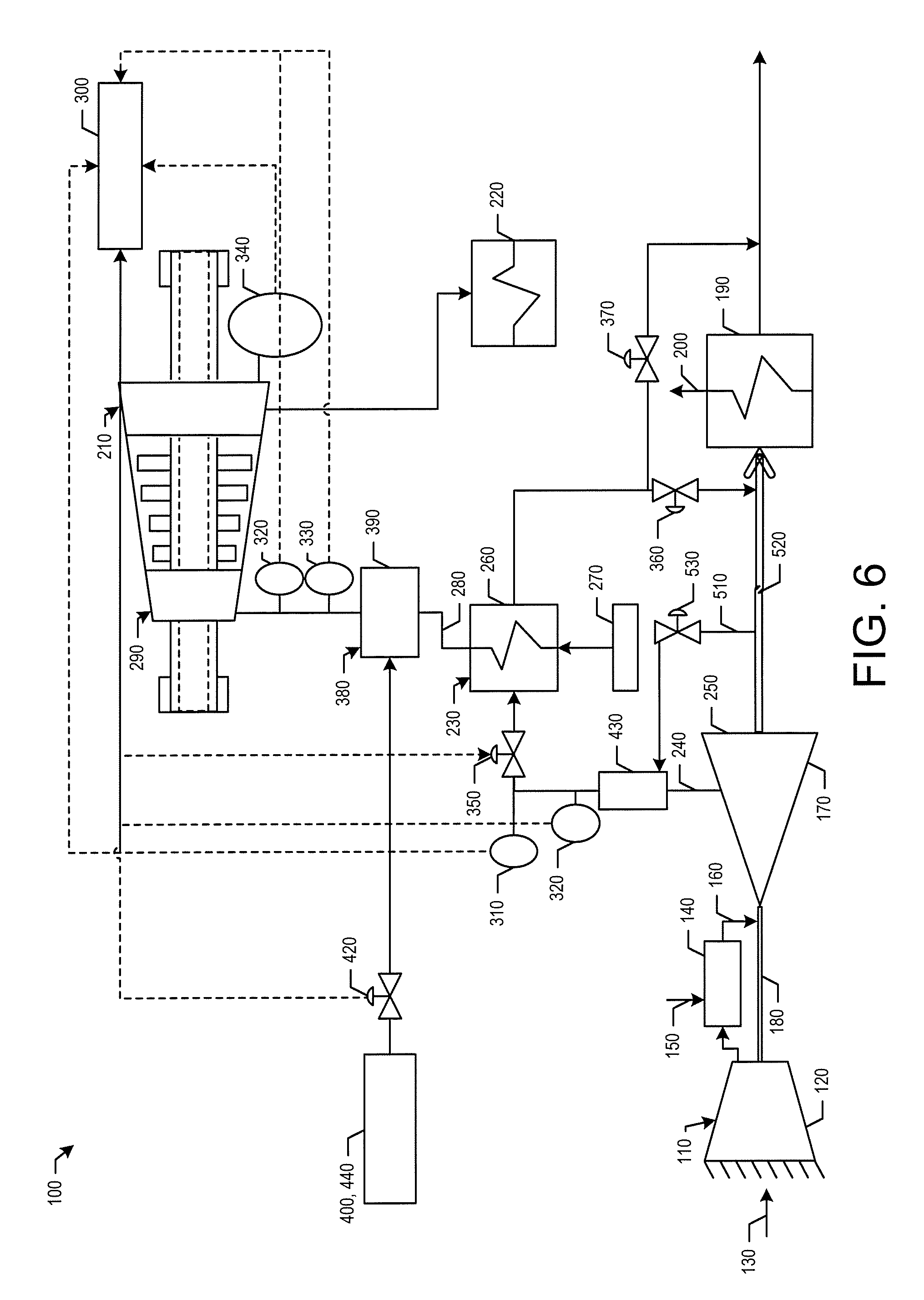
FIG. 6 is a schematic diagram of an alternative embodiment of a combined cycle power generation system with a steam turbine preheating system as may be described herein.
DETAILED DESCRIPTION
Referring now to the drawings, in which like numerals refer to like elements throughout the several views, FIG. 1 shows a schematic diagram of a combined cycle power generation system 100 as may be described herein. The combined cycle power generation system 100 may include a gas turbine engine 110. The gas turbine engine 110 may include a compressor 120. The compressor 120 compresses an incoming flow of air 130. The compressor 120 delivers the compressed flow of air 130 to a combustor 140. The combustor 140 mixes the compressed flow of air 130 with a pressurized flow of fuel 150 and ignites the mixture to create a flow of hot combustion gases 160. Although only a single combustor 140 is shown, the gas turbine engine 110 may include any number of combustors 140 positioned in a circumferential array or otherwise. The flow of combustion gases 160 is in turn delivered to a turbine 170. The flow of combustion gases 160 drives the turbine 170 so as to produce mechanical work. The mechanical work produced in the turbine 170 drives the compressor 120 via a shaft 180 and an external load such as an electrical generator and the like.
The gas turbine engine 110 may use natural gas, various types of syngas, liquid fuels, and/or other types of fuels and blends thereof. The gas turbine engine 110 may be any one of a number of different gas turbine engines offered by General Electric Company of Schenectady, N.Y., including, but not limited to, a 7 or a 9 series heavy duty gas turbine engine and the like. The gas turbine engines 110 may have many different configurations and may have other types of components. Other types of gas turbine engines also may be used herein. Multiple gas turbine engines, other types of turbines, and other types of power generation equipment also may be used herein together.
The combined cycle power generation system 100 may include a heat recovery steam generator 190. The heat recovery steam generator 190 may recover heat from the hot combustion gases 160 exiting the gas turbine engine 110 so as to create a flow of steam 200. The heat recovery steam generator 190 may be of conventional design and may include one or more pressure sections such as a high pressure section, an intermediate pressure section, and a low pressure section. Each pressure section may include any combination of evaporators, superheaters, economizers, and the like. Other components and other configurations may be used herein.
The combined cycle power generation system 100 also may include a steam turbine 210. The steam turbine 210 may be of conventional design and may include one or more pressure sections such as a high pressure section, an intermediate pressure section, and a low pressure section. The flows of steam 200 from the heat recovery generator 190 may be expanded in the steam turbine 210 so as to drive an additional load such as an electrical generator and the like. The steam turbine 210 may include a condenser 220 for the recovery of the spent fluid flow therein. Other components and other configurations may be used herein.
The combined cycle power generation system 100 also may include a steam turbine preheating system 230. The steam turbine preheating system 230 may include one or more extractions 240 of the hot combustion gases 160 from a casing 250 of the turbine 170 or elsewhere. The casing 250 may be modified to include flanges at various stages to allow for the extractions 240. The extractions 240 may be in communication with a steam generator 260. The steam generator 260 may be of conventional design. Specifically, the steam generator 260 may be a heat exchanger that exchanges heat between the hot combustion gases 160 from the turbine 170 and a flow of feedwater 270 from any source so as to create a flow of steam 280. The flow of steam 280 may be sent to a shell 290 of the steam turbine 210 so as to preheat the steam turbine 210 before and/or during start-up. The steam/condensate exiting the steam turbine shell 290 may pass into the condenser 220 or otherwise. The extracted combustion gases 160 passing through the steam turbine 210 may flow either upstream of the heat recovery steam generator 190 so as to exchange heat therein or downstream of the heat recovery steam generator 190 towards the main stack or otherwise. Other components and other configurations may be used herein.
Overall control of the steam turbine preheating system 230 may be governed via a controller 300. The controller 300 may be any type of programmable logic device. The controller 300 may be local or remote. The controller 300 may receive data from a number of sensors in communication with the steam turbine preheating system 230. These sensors may include a flow rate sensor 310, one or more temperature sensors 320, a pressure sensor 330, and the like. Other types of sensors may be used herein. Based upon the data from the sensors and the overall steam turbine controls 340, the controller 300 may open and close the steam turbine preheating system 230 via an inlet valve 350 and one or more outlet valves. In this embodiment, a first outlet valve 360 and a second outlet valve 370 are shown. Other types of flow control devices and the like also may be used herein. Other components and other configurations may be used herein.
In use, the controller 300 may receive information on overall operational parameters of the steam turbine 210 via the steam turbine controls 340 including, for example, the temperature of the rotor and/or the blades. In order to preheat the steam turbine 210, the controller 300 may open the inlet valve 350 of the steam turbine preheating system 230 so as to allow the extraction 240 of the hot combustion gases 160 from the turbine casing 250 to flow to the steam generator 260. The hot combustion gases 160 exchange heat with the flow of feedwater 270 in the steam generator 260 so as to create the flow of steam 280. The flow of steam 280 thus may be used to warm the steam turbine shell 290.
The controller 300 may monitor the flow rate and the temperature of the extraction 240 upstream of the steam generator 290 via the flow rate sensor 310 and one of the temperature sensors 320. The controller 300 also may monitor the temperature and pressure of the steam 280 downstream of the steam generator 260 via one of the temperature sensors 320 and the pressure sensor 330. Once the steam turbine 210 reaches a predetermined temperature, the controller 300 may turn off the steam turbine preheating system 230 by closing the inlet valve 350 or otherwise. Closing the inlet valve 350 directs all of the combustion gases 160 towards the turbine 170 and the heat recovery steam generator 190. Other components and other configurations may be used herein.
FIG. 2 shows a further embodiment of the steam turbine preheating system 230 as may be described herein. In this example, the steam turbine preheating system 230 may include an attemperation system 380 positioned downstream of the steam generator 260. The attemperation system 380 may include a spray system 390 in communication with either a water injection 400 or a steam injection 410 via a spray system valve 420. The spray system 390 may be an in-line mixer, a spray chamber, or any type of conventional device for tempering a fluid flow. Specifically, the spray system 390 may use either the water injection 400 or the steam injection 410 for temperature control of the flow of steam 280 exiting the steam generator 260. The controller 300 may operate the attemperation system 380 via the spray system valve 420 based upon the temperature of the flow of steam 280 as determined by one of the temperature sensors 320 or otherwise. Other components and other configurations may be used herein.
FIG. 3 shows a further embodiment of the steam turbine preheating system 230 as may be described herein. In this example, an ejector 430 may be positioned on the extraction 240 from the casing 250 of the turbine 170. The ejector 430 may be in communication with a source of ambient air 440 or filtered air 450 via an ejector valve 460. The ejector 430 pulls in the ambient air or the filtered air so as to increase the mass flow rate of the flow of hot combustion gases 160 flowing through the steam generator 260. The ejector 430 may be of conventional design. Specifically, the ejector 430 may be a mechanical device with no moving parts. The ejector 430 mixes two fluid streams based on a momentum transfer. The flow of ambient air or filtered air to the ejector 430 may be controlled by an ejector valve 460. The flow rate may be monitored by the controller 300 via the flow rate sensor 310 or otherwise. Other components and other configurations may be used herein.
FIG. 4 shows a further embodiment of the steam turbine preheating system 230 as may be described herein. In this example, the ejector 430 may use a compressor air extraction 470 instead of the ambient air 440 or the filtered air 450 described above. The compressor air extraction 470 may be delivered to the ejector 430 so as to increase the mass flow rate to the steam generator 260. The flow rate may be monitored by the controller 300 via the flow rate sensor 310 or otherwise. Other components and other configurations may be used herein.
FIG. 5 shows a further embodiment of the steam turbine preheating system 230 as may be described herein. In this example, the steam turbine preheating system 230 may use a cascading ejector system 480. The cascading system ejector system 480 may use a first ejector 490. The first ejector 490 may pull in either the ambient air 440 or the filtered air 450 and the compressor air extraction 470 to create a first mixed flow. This first mixed flow then may be sent to a second ejector 500. The second ejector 500 may be in communication with the extraction 240 from the casing 250 of the turbine 170. The resultant flow then may be forwarded to the steam generator 260 to increase the mass flow rate therethrough. The flow rate may be monitored by the controller 300 via the flow rate sensor 310 or otherwise. Other components and other configurations may be used herein.
FIG. 6 shows a further embodiment of the steam turbine preheating system 230 as may be described herein. In this embodiment, the ejector 430 may be in communication with a further combustion gas extraction 510 from downstream of the turbine 170 or otherwise. Specifically, a downstream exhaust duct 520 may direct the further combustion gas extraction 510 to the ejector 430 via an exhaust valve 530. The extractions 240, 510 may be mixed in the ejector 430 so as to increase the mass flow rate therethrough. The flow rate may be monitored by the controller 300 via the flow rate sensor 310 or otherwise. Other components and other configurations also may be used herein.
The embodiments of the steam turbine preheating system 230 thus may use the extractions 240 of the hot combustion gases 160 from the casing 250 of the turbine 170 so as to create a flow of steam 280 in the steam generator 260. The flow of steam 280 may be used in turn to preheat the steam turbine 210. Preheating the steam turbine 210 during start-up should reduce the overall start-up time of the plant as a whole. Specifically, the plant may not have to wait for traditional steam conditions to be met before introducing steam to the steam turbine to begin the warming process. Reducing start-up time generally lowers emissions and improves fuel consumption. Moreover, improved-start up times also provides operational flexibility, increased performance, and increased competitiveness.
It should be apparent that the foregoing relates only to certain embodiments of the present application and the resultant patent. Numerous changes and modifications may be made herein by one of skill in the art without departing from the general spirit and scope of the invention as defined by the following claims and the equivalents thereof.
* * * * *
D00000
D00001
D00002
D00003
D00004
D00005
D00006
XML
uspto.report is an independent third-party trademark research tool that is not affiliated, endorsed, or sponsored by the United States Patent and Trademark Office (USPTO) or any other governmental organization. The information provided by uspto.report is based on publicly available data at the time of writing and is intended for informational purposes only.
While we strive to provide accurate and up-to-date information, we do not guarantee the accuracy, completeness, reliability, or suitability of the information displayed on this site. The use of this site is at your own risk. Any reliance you place on such information is therefore strictly at your own risk.
All official trademark data, including owner information, should be verified by visiting the official USPTO website at www.uspto.gov. This site is not intended to replace professional legal advice and should not be used as a substitute for consulting with a legal professional who is knowledgeable about trademark law.