Storage device with infinitely adjustable storage divider system
Prezecki, II
U.S. patent number 10,336,504 [Application Number 14/944,889] was granted by the patent office on 2019-07-02 for storage device with infinitely adjustable storage divider system. This patent grant is currently assigned to Ford Global Technologies, LLC. The grantee listed for this patent is FORD GLOBAL TECHNOLOGIES, LLC. Invention is credited to Leonard Gus Prezecki, II.


| United States Patent | 10,336,504 |
| Prezecki, II | July 2, 2019 |
Storage device with infinitely adjustable storage divider system
Abstract
A storage device is provided. That storage device includes a sidewall defining a storage compartment and a storage divider system including a hub. That hub is held in the storage compartment and a plurality of telescoping panels extend between the hub and the sidewall to divide the storage compartment into individual chambers.
| Inventors: | Prezecki, II; Leonard Gus (Ann Arbor, MI) | ||||||||||
|---|---|---|---|---|---|---|---|---|---|---|---|
| Applicant: |
|
||||||||||
| Assignee: | Ford Global Technologies, LLC
(Dearborn, MI) |
||||||||||
| Family ID: | 58640525 | ||||||||||
| Appl. No.: | 14/944,889 | ||||||||||
| Filed: | November 18, 2015 |
Prior Publication Data
| Document Identifier | Publication Date | |
|---|---|---|
| US 20170137177 A1 | May 18, 2017 | |
| Current U.S. Class: | 1/1 |
| Current CPC Class: | B65D 25/06 (20130101) |
| Current International Class: | B65D 25/06 (20060101) |
| Field of Search: | ;220/528-533,551 ;312/401-402,404,407,348.3 ;62/382 ;248/173,448,458,460 ;D7/555,387,549 ;249/131,171 ;D3/313 ;206/708 ;211/70.6,106,133.4,107,169,169.1,165,97,69,78,163,85.23 |
References Cited [Referenced By]
U.S. Patent Documents
| 1290186 | January 1919 | Held |
| 2903127 | September 1959 | Dorman |
| 3720346 | March 1973 | Cypher |
| 4736856 | April 1988 | Alneng |
| 4966295 | October 1990 | Parrish |
| 5074777 | December 1991 | Garner |
| D384861 | October 1997 | Richard |
| D395377 | June 1998 | Wallays |
| 6105654 | August 2000 | Martel |
| 6871921 | March 2005 | Ernst |
| 7163119 | January 2007 | Besselman |
| 8281939 | October 2012 | Chen |
| 2001/0004817 | June 2001 | Auer |
| 2004/0020055 | February 2004 | Zuker |
| 2006/0099057 | May 2006 | Fair |
| 2006/0272466 | December 2006 | Atwater |
| 2008/0041799 | February 2008 | Nguy |
| 2008/0129167 | June 2008 | Rand |
| 2009/0063166 | March 2009 | Palmer |
| 2009/0255891 | October 2009 | Lanning |
| 2010/0319391 | December 2010 | Lim |
| 2014/0210331 | July 2014 | Tunzi |
| 2014/0238995 | August 2014 | Vargas |
| 2014/0265802 | September 2014 | Wilcox |
| 2014/0290069 | October 2014 | White, III |
| 2015/0208840 | July 2015 | Honeycutt |
| 2015/0239631 | August 2015 | Kinskey |
| 101508376 | Aug 2009 | CN | |||
| 201545274 | Aug 2010 | CN | |||
| 201816520 | May 2011 | CN | |||
| 202163735 | Mar 2012 | CN | |||
| 102005037188 | Feb 2007 | DE | |||
| 102008049759 | Apr 2010 | DE | |||
| 102011100835 | Mar 2012 | DE | |||
| 1854672 | Sep 2009 | EP | |||
Other References
|
English machine translation of CN201816520U. cited by applicant . English machine translation of DE102005037188A1. cited by applicant . English machine translation of DE102008049759A1. cited by applicant . English machine translation of DE102011100835B3. cited by applicant . English machine translation of EP1854672A3. cited by applicant . English Machine Translation of CN101508376A dated Aug. 19, 2009. cited by applicant . English Machine Translation of CN201545274U dated Aug. 11, 2010. cited by applicant . English Machine Translation of CN202163735U dated Mar. 14, 2012. cited by applicant . Notification of First Office Action from State Intellectual Property Office of the People's Republic of China Application No. 201610994066.6 dated Mar. 25, 2019. cited by applicant. |
Primary Examiner: Cheung; Chun Hoi
Assistant Examiner: Patel; Brijesh V.
Attorney, Agent or Firm: Chea; Vichit King & Schickli, PLLC
Claims
What is claimed:
1. A storage device, comprising: a sidewall defining a storage compartment, said sidewall including a guide track wherein said guide track extends continuously along said sidewall and includes radiused corners; a hub held in said storage compartment, said hub including a plurality of hinge keys; and a plurality of telescoping panels extending between said hub and said sidewall and dividing said storage compartment into individual chambers, wherein each panel of said plurality of panels includes a guide roller that is captured in and follows said guide track.
2. The storage device of claim 1, wherein said hub is displaceable within said storage compartment relative to said sidewall.
3. The storage device of claim 2, wherein said hub includes a lock for securing said plurality of telescoping panels in any selected positions.
4. The storage device of claim 3, wherein said hub includes a plurality of hinge keys and each panel of said plurality of said telescoping panels includes a keyway for receiving and holding one hinge key of said plurality of hinge keys.
5. The storage device of claim 4, wherein said plurality of hinge keys are received on a shaft.
6. The storage device of claim 5, wherein an end of said shaft is threaded.
7. The storage device of claim 6, wherein said lock comprises a knob that is received on said threaded end of said shaft and tightened to lock said plurality of telescoping panels in any selected position.
8. The storage device of claim 1, wherein each panel of said plurality of panels includes a stabilizer rib.
9. The storage device of claim 8, wherein said sidewall includes a locator channel for receiving said stabilizer rib of each panel of said plurality of telescoping panels.
10. The storage device of claim 9, wherein said locator channel extends continuously along said sidewall.
11. The storage device of claim 1, wherein said storage device includes a bottom wall, said sidewall is fixed to said bottom wall and said hub is displaceable along said bottom wall within said sidewall.
Description
TECHNICAL FIELD
This document relates generally to the storage device field and, more particularly, to a storage compartment equipped with an infinitely adjustable storage divider system for dividing the storage compartment into individual chambers customized to meet the needs of the user.
BACKGROUND
It has long been known to provide dividers in a storage compartment in order to partition the storage compartment into individual chambers. Such prior art dividers do not offer the user with a way to truly and effectively customize the storage compartment to hold the items which the individual wishes to store.
This document relates to a new and improved storage device wherein the storage compartment of that device includes a storage divider system having a displaceable hub and a plurality of telescoping panels that extend between the hub and the sidewall of the storage compartment. Advantageously, such a system allows the user to divide the storage compartment into what amounts to a virtually infinite number of individual chamber configurations. Thus, the storage device disclosed herein allows one to fully customize the storage chamber to effectively meet the needs of any particular application and hold various items as desired by the user.
SUMMARY
In accordance with the purposes and benefits described herein, a storage device is provided. That storage device comprises a sidewall defining a storage compartment and a hub held in the storage compartment. Further, the storage device includes a plurality of telescoping panels that extend between the hub and the sidewall. Those telescoping panels divide the storage compartment into individual chambers in substantially any configuration desired by the user.
Significantly, the hub is displaced within the storage compartment relative to the sidewall. The hub includes a lock for securing the plurality of the telescoping panels in any selected position. Further the hub includes a plurality of hinge keys and each panel of the plurality of telescoping panels includes a keyway for receiving and holding one hinge key of the plurality of hinge keys.
The plurality of hinge keys may be received on a shaft. The end of that shaft may be threaded. Further, in one possible embodiment the lock comprises a knob that is received on the threaded end of the shaft. When that knob is tightened down on the threaded shaft, the plurality of telescoping panels are secured and locked in selected positions.
In accordance with a further aspect, the sidewall may include a guide track. Further each panel of the plurality of telescoping panels may include a guide roller that is captured in and follows that guide track.
In one particularly useful embodiment, the guide track extends continuously along the sidewall and includes radiused corners.
Each panel of the plurality of panels may include a stabilizer rib. Further, the sidewall may include a locator channel for receiving the stabilizer rib of each panel of the plurality of telescoping panels. In one particularly useful embodiment, that locator channel extends continuously along the sidewall. Together, the continuous guide track and the continuous locator channel provide for substantially infinite adjustability of the plurality of telescoping panels as they extend from the hub to the sidewall.
In one possible embodiment, the storage device includes a bottom wall. The sidewall is fixed to the bottom wall while the hub is displaceable along the bottom wall within the sidewall.
In accordance with an additional aspect, a method is provided for dividing a storage compartment into an infinite configuration of individual chambers. That method may be broadly described as comprising the steps of: (1) providing a storage compartment within a sidewall and (2) positioning a storage divider system within that sidewall. The storage divider system includes a hub and a plurality of telescoping panels extending between the hub and the sidewall to divide the storage compartment into the individual chambers.
The method may further include the step of reconfiguring the individual chambers by displacing the hub within the storage compartment. Further, the method may include reconfiguring the individual chambers by changing the included angle defined at the hub between any two adjacent panels of the plurality of telescoping panels. Still further, the method may include reconfiguring the individual chambers by increasing or decreasing the number of the plurality of telescoping panels extending between the hub and the sidewall. Any one or a combination of any two or all three of these reconfiguring steps may be utilized to allow an individual to customize the storage compartment with individual chambers suited to meet the needs of the user.
In the following description, there are shown and described several preferred embodiments of the storage device. As it should be realized, the storage device is capable of other, different embodiments and its several details are capable of modification in various, obvious aspects all without departing from the storage device as set forth and described in the following claims. Accordingly, the drawings and descriptions should be regarded as illustrative in nature and not as restrictive.
BRIEF DESCRIPTION OF THE DRAWING FIGURES
The accompanying drawing figures incorporated herein and forming a part of the specification, illustrate several aspects of the storage device and together with the description serve to explain certain principles thereof. In the drawing figures:
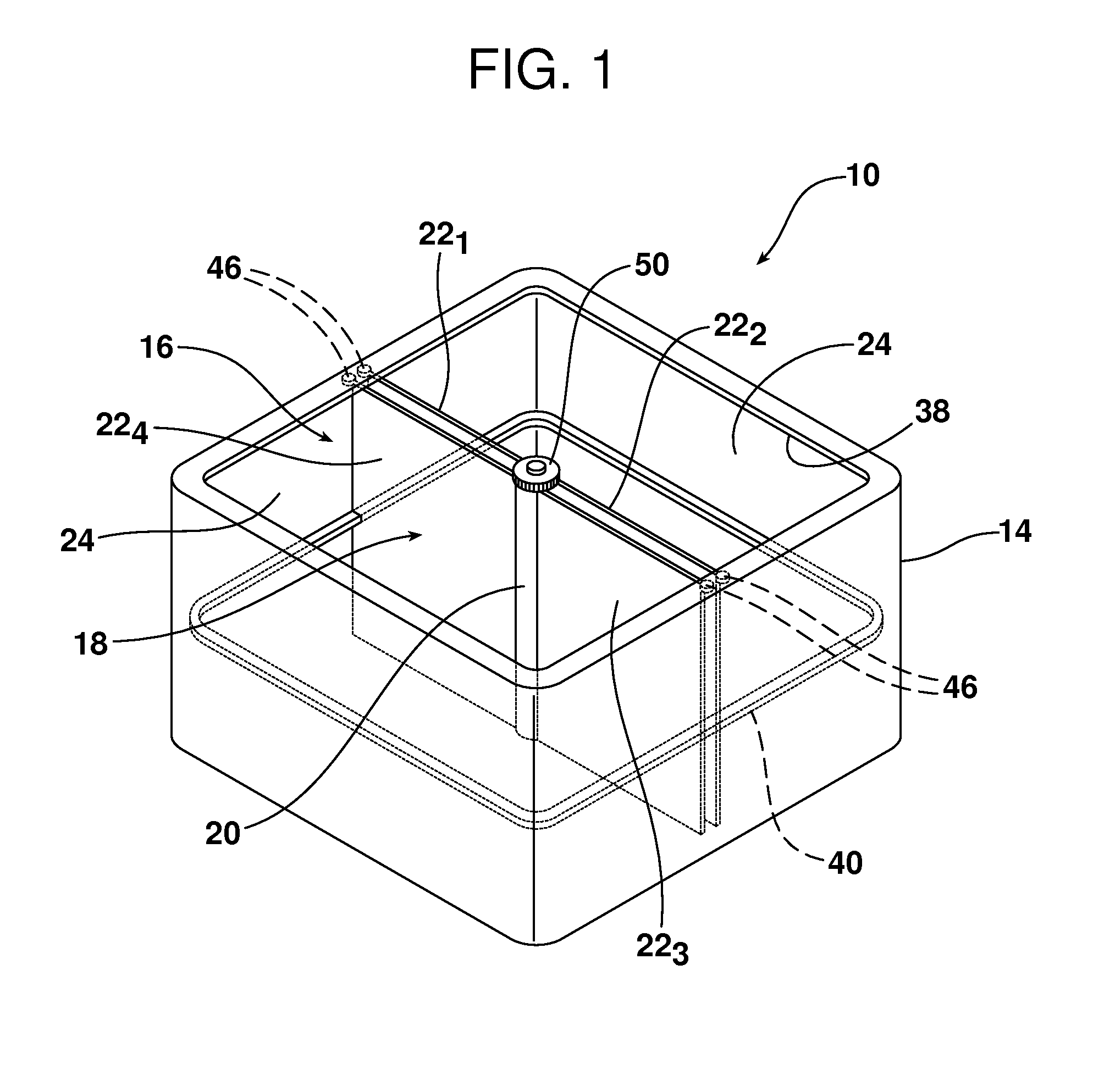
FIG. 1 is a perspective view of the storage device.
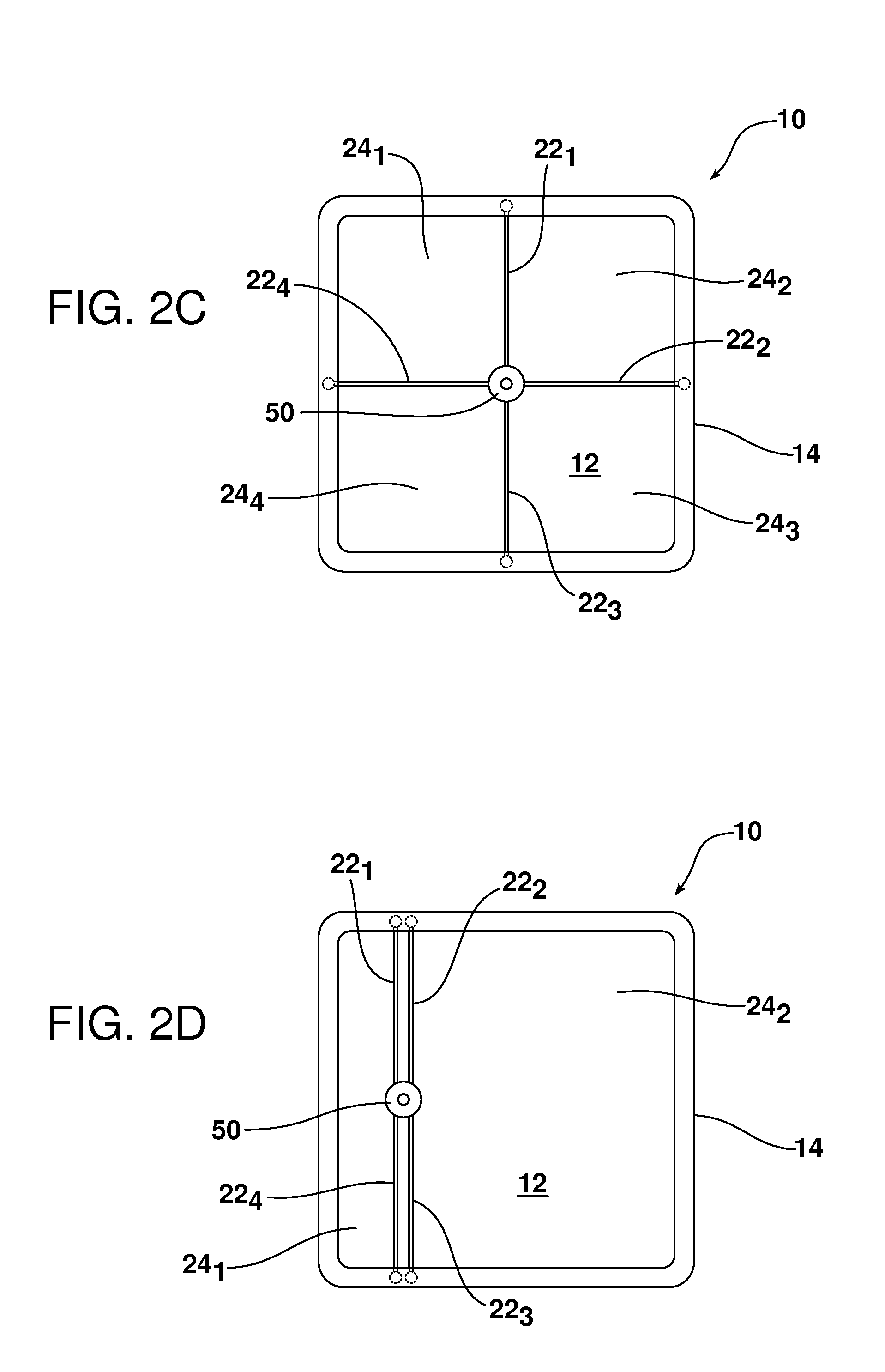
FIGS. 2A-2E illustrate only five of a potentially infinite number of ways the storage compartment may be configured into individual chambers.
FIG. 3 is a detailed top plane view of yet another possible configuration illustrating how the storage device may be easily configured to hold a tablet or a phone in one compartment and a beverage can in another.
FIG. 4 is a schematic side elevational view illustrating in detail the hub and sidewall of the storage device as well as two of the plurality of telescoping panels extending between the hub and the sidewall that are utilized to divide the storage compartment into individual chambers.
FIG. 5 is a detailed top plan view of the hub and the cooperating keyways in the telescoping panels that connect the telescoping panels to the hub via the hinge keys.
Reference will now be made in detail to the present preferred embodiments of the storage device, examples of which are illustrated in the accompanying drawing figures.
DETAILED DESCRIPTION
Reference is now made to FIGS. 1-5 illustrating the storage device 10 which includes a bottom wall 12 and a sidewall 14 defining a storage compartment 16. As illustrated, the storage device 10 also includes a storage divider system 18 comprised of a hub 20 and a plurality of telescoping panels 22.sub.1, 22.sub.2, 22.sub.3, 22.sub.4. As illustrated, the plurality of telescoping panels 22.sub.1-22.sub.4 extend between the hub 20 and the sidewall 14 dividing the storage compartment 16 into individual chambers 24.sub.1-24.sub.n. In the embodiment illustrated in FIGS. 1-3, the storage device 10 includes four telescoping panels 22.sub.1-22.sub.4. As should be appreciated, however, the storage device 10 may include substantially any desired number of telescoping panels 22.sub.1-22.sub.n to divide the storage compartment 16 into any number of desired chambers 24.sub.1-24.sub.n. In most applications the storage device 10 will include between two and six telescoping panels 22.sub.1-22.sub.n. As should be appreciated, however, if desired, the storage device 10 may include only one telescoping panel 22.sub.1 or as many telescoping panels as desired above six.
As should be appreciated for reviewing FIGS. 2A-2E, the hub 20 of the storage device 10 is displaceable along the bottom wall 12 and within the sidewall 14 into substantially any desired position. Further, the included angle defined between any two adjacent telescoping panels 22.sub.1-22.sub.n may also be adjusted as desired. As a result, each storage compartment 16 may be divided into a substantially infinite number of different chamber configurations. Five such configurations are illustrated in FIGS. 2A-2E.
FIG. 3 illustrates yet another configuration including one chamber 24.sub.1 sized and shaped to hold a tablet or phone T, a second chamber 24.sub.2 sized and shaped to hold a drinking beverage B and two additional storage chambers 24.sub.3 and 24.sub.4 for holding substantially any other article desired by the user.
Reference is now made to FIGS. 4 and 5 illustrating the structural aspects of the storage divider system 18 including, particularly, the hub 20, the sidewall 14 and the telescoping panels 22.sub.1-22.sub.n that allow the storage compartment 16 to be divided into substantially any configuration of chambers 24.sub.1-24.sub.n.
As illustrated, the hub 20 includes a plurality of hinge keys 26.sub.1-26.sub.n. Each hinge key 26.sub.1-26.sub.n comprises a cylindrical shaped body 28.sub.1-28.sub.n, a projecting key 30.sub.1-30.sub.n and a central aperture 32 in the body. As illustrated, the hinge keys 26.sub.1-26.sub.n are stacked onto a shaft 34 so that the shaft extends through the central aperture 32 in the body 28.sub.1-28.sub.nof each hinge key. As further illustrated, at least the end 36 of the shaft 34 is threaded.
The sidewall 14 includes a guide track 38. That guide track 38 extends continuously along the sidewall 14 and includes radiused corners (see also FIG. 1). In addition, the sidewall 14 includes a locator channel 40 that also extends continuously along the sidewall including around the radiused corners.
As best illustrated in FIGS. 4 and 5, each panel 22.sub.1-22.sub.n of the plurality of telescoping panels has a telescoping body. In the illustrated embodiment, that telescoping body includes three sections 42.sub.1, 42.sub.2 and 42.sub.3. One end of each panel 22.sub.1-22.sub.n includes a keyway 44 for receiving and holding one key 30.sub.1-30.sub.n of the hinge keys 26.sub.1-26.sub.nand thereby connecting that first end of the panel 22.sub.1-22.sub.nto the hub 20.
The second or opposite end of each panel 22.sub.1-22.sub.n of the plurality of panels includes a guide roller 46 that is captured in and follows the guide track 38 of the sidewall 14. Further, each panel 22.sub.1-22.sub.n of the plurality of telescoping panels includes a projecting stabilizer rib 48 that is freely received in the locator channel 40 of the sidewall 14. Thus, it should be appreciated that each panel 22.sub.1-22.sub.n includes a guide roller 46 and a stabilizer rib 48 on an end thereof opposite the keyway 44. Together, the guide roller 46 and stabilizer group 48 connect this second end of each panel 22.sub.1-22.sub.n to the sidewall 14. Thus, it should be appreciated that each telescoping panel 22.sub.1-22.sub.n extends continuously between the hub 20 and the sidewall 14.
As should be appreciated the individual chambers 24 of the storage compartment 16 may be reconfigured by: (1) displacing the hub 20 along the bottom wall 12 in the storage compartment 16 and/or (2) changing the included angle defined at the hub 20 between any two adjacent panels 22.sub.1-22.sub.n of the plurality of telescoping panels by rotating the hinge keys 26.sub.1-26.sub.n on the shaft 34 and/or (3) increasing or decreasing the number of the plurality of telescoping panels 22.sub.1-22.sub.n extending between the hub 20 and the sidewall 14. As should be appreciated, the telescoping body of each panel 22.sub.1-22.sub.n, the guide roller 46 on each panel captured in the continuous guide track 38 of the sidewall 14 and the stabilizer rib 48 received and sliding through the continuous locator channel 40 in the sidewall 14 accommodate any repositioning of any of the telescoping panels while maintaining those panels so that they fully extend between the hub 20 and the sidewall 14.
Once the hub 20 and telescoping panels 22.sub.1-22.sub.n of the storage divider system 18 have been positioned as desired to divide the storage compartment 16 into a desired, customized arrangement of chambers 24.sub.1-24.sub.n, the storage divider system 18 is locked in place. More specifically, the lock in the illustrated embodiment comprises a knob 50 that is threadedly received on the threaded end 36 of the hub shaft 34. When knob 50 is tightened down, the hinge keys 26.sub.1-26.sub.n are secured in position thereby holding all of the telescoping panels 22.sub.1-22.sub.n in place. If and when one wishes to reconfigure the various chambers 24.sub.1-24.sub.n of the storage device 10, the knob 50 may be loosened and the relative position of the hub 20 and the telescoping panels 22.sub.1-22.sub.n with respect to the sidewall 14 may be adjusted as desired. The knob 50 may then be tightened down again to once again secure the storage divider system 18 in position in order to maintain the new customized configuration of the storage device 10.
The foregoing has been presented for purposes of illustration and description. It is not intended to be exhaustive or to limit the embodiments to the precise form disclosed. Obvious modifications and variations are possible in light of the above teachings. All such modifications and variations are within the scope of the appended claims when interpreted in accordance with the breadth to which they are fairly, legally and equitably entitled.
* * * * *
D00000
D00001
D00002
D00003
D00004
D00005
D00006
D00007
XML
uspto.report is an independent third-party trademark research tool that is not affiliated, endorsed, or sponsored by the United States Patent and Trademark Office (USPTO) or any other governmental organization. The information provided by uspto.report is based on publicly available data at the time of writing and is intended for informational purposes only.
While we strive to provide accurate and up-to-date information, we do not guarantee the accuracy, completeness, reliability, or suitability of the information displayed on this site. The use of this site is at your own risk. Any reliance you place on such information is therefore strictly at your own risk.
All official trademark data, including owner information, should be verified by visiting the official USPTO website at www.uspto.gov. This site is not intended to replace professional legal advice and should not be used as a substitute for consulting with a legal professional who is knowledgeable about trademark law.