Wheel lightweight machining fixture and method
Liu , et al.
U.S. patent number 10,335,859 [Application Number 15/797,345] was granted by the patent office on 2019-07-02 for wheel lightweight machining fixture and method. This patent grant is currently assigned to CITIC Dicastal CO., LTD.. The grantee listed for this patent is CITIC Dicastal CO.,LTD.. Invention is credited to Weimin Cai, Changhai Li, Huiying Liu, Yajun Wang.

| United States Patent | 10,335,859 |
| Liu , et al. | July 2, 2019 |
Wheel lightweight machining fixture and method
Abstract
Disclosed are a wheel lightweight machining fixture and method. The fixture comprises a rotating chuck, an electric cylinder, a guide rail, a slide block, a first linear motor, radial positioning blocks and the like. When the electric cylinder drives the slide block to move along the guide rail, the position where an first ultrasonic thickness measuring sensor is in contact with a wheel spoke can be adjusted, so that the spoke thicknesses at different positions can be detected. Through motion of the turrets, an second ultrasonic thickness measuring sensor can contact the outer rim of the wheel and detect the rim wall thickness. By integrating a measurement feedback system into the manufacturing process, the disclosure provides a fixture and a method for minimum entity machining of the rim wall thickness and the spoke thickness of a wheel during the first stage turning process, thereby realizing lightweight manufacturing of the wheel.
| Inventors: | Liu; Huiying (Qinhuangdao, CN), Li; Changhai (Qinhuangdao, CN), Cai; Weimin (Qinhuangdao, CN), Wang; Yajun (Qinhuangdao, CN) | ||||||||||
|---|---|---|---|---|---|---|---|---|---|---|---|
| Applicant: |
|
||||||||||
| Assignee: | CITIC Dicastal CO., LTD.
(Qinhuangdao, CN) |
||||||||||
| Family ID: | 60346902 | ||||||||||
| Appl. No.: | 15/797,345 | ||||||||||
| Filed: | October 30, 2017 |
Prior Publication Data
| Document Identifier | Publication Date | |
|---|---|---|
| US 20190061007 A1 | Feb 28, 2019 | |
Foreign Application Priority Data
| Aug 27, 2017 [CN] | 2017 1 0746876 | |||
| Current U.S. Class: | 1/1 |
| Current CPC Class: | G01B 17/02 (20130101); B23P 13/02 (20130101); B23B 5/28 (20130101); B60B 30/06 (20130101); B23B 3/10 (20130101); B23B 2260/128 (20130101); B23B 2270/10 (20130101); B60B 2900/111 (20130101); B23B 13/02 (20130101); B60B 2310/231 (20130101); B23B 2215/08 (20130101); B60B 2900/112 (20130101) |
| Current International Class: | B23B 5/28 (20060101); B23B 3/10 (20060101); B60B 30/06 (20060101); G01B 17/02 (20060101); B23B 13/02 (20060101) |
References Cited [Referenced By]
U.S. Patent Documents
| 493738 | March 1893 | Streit |
| 521353 | June 1894 | Wood |
| 3483795 | December 1969 | Wranosky |
| 4318293 | March 1982 | Heymanns |
| 4470637 | September 1984 | Kopp |
| 4699433 | October 1987 | Kopp |
| 5081889 | January 1992 | Takano |
| 5842388 | December 1998 | Visser |
| 6415508 | July 2002 | Laps |
| 6502834 | January 2003 | Fukui |
| 7185573 | March 2007 | Gatton |
| 2004/0123707 | July 2004 | Kroener |
| 2006/0042091 | March 2006 | Luschei |
| 2007/0227318 | October 2007 | Biertz |
| 2012/0073413 | March 2012 | Len |
| 2015/0273588 | October 2015 | Bowen |
| 2017/0312834 | November 2017 | Guo |
| 2018/0001695 | January 2018 | Liu |
| 102554199 | Jul 2012 | CN | |||
Attorney, Agent or Firm: Cooper Legal Group, LLC
Claims
The invention claimed is:
1. A wheel lightweight machining fixture, comprising a rotating chuck, an electric cylinder, a guide rail, a slide block, a first linear motor, a first piezoelectric sensor, a first ultrasonic thickness measuring sensor, a first vertical lathe turret, a second linear motor, a clamping base for clamping the second linear motor, a second piezoelectric sensor, a second ultrasonic thickness measuring sensor, and a central hole flange turning tool for turning a central hole and a flange surface of a wheel, wherein two grooves are bilaterally distributed in the rotating chuck, the electric cylinder and the guide rail being fixedly mounted in a left groove of the two grooves, the slide block is mounted on the guide rail, an output end of the electric cylinder is connected with the slide block, the first linear motor is fixedly mounted on the slide block, the first ultrasonic thickness measuring sensor is mounted at an output end of the first linear motor, and the first piezoelectric sensor is located inside the first ultrasonic thickness measuring sensor; when the electric cylinder drives the slide block to move along the guide rail, the first ultrasonic thickness measuring sensor can be in contact with different positions on a spoke of the wheel, so that a spoke thicknesses at different positions can be detected.
2. The wheel lightweight machining fixture of claim 1, wherein the clamping base is mounted on the first vertical lathe turret, the second linear motor is mounted on the clamping base, the second ultrasonic thickness measuring sensor is mounted at an output end of the second linear motor, and the second piezoelectric sensor is located inside the second ultrasonic thickness measuring sensor; through vertical movement and horizontal movement of the first vertical lathe turret, the second ultrasonic thickness measuring sensor can contact an outer rim of the wheel and detect a rim wall thickness.
3. The wheel lightweight machining fixture of claim 1, wherein the wheel having a front side downward and a rim upward is clamped onto the rotating chuck, and the spoke of the wheel is required to face the first ultrasonic thickness measuring sensor during clamping.
Description
CROSS-REFERENCE TO RELATED APPLICATIONS
The present application claims benefit of Chinese Patent Application No. 201710746876.4, filed on Aug. 27, 2017, the contents of which are hereby incorporated by reference in its entirety.
BACKGROUND
On the premise of meeting the safety performance, wheels are gradually developed toward lightweight, and the lightweight of the wheels is not only beneficial to reducing the resistance and oil consumption of automobiles, but also improves the rotating and braking performance of the wheels. For wheel manufacturing enterprises, the weights of wheels are reduced, and aluminum scraps can be recycled to reduce the manufacturing cost, so lightweight manufacturing of wheels is an important technology. In the machining process of wheels, minimum entity manufacturing is an effective way for realizing lightweight production of wheels, i.e., the sizes of wheels are controlled according to minimum entities. The rim wall thicknesses and spoke thicknesses of wheels are key parts influencing the weights of the wheels, so in order to realize lightweight machining minimum entity control must be performed on the rim thicknesses and the spoke thicknesses.
SUMMARY
The disclosure relates to the technical fields of wheel weight reduction and lightweight manufacturing, specifically to a wheel lightweight machining fixture and a lightweight machining method.
The disclosure is aimed at providing a wheel lightweight machining fixture and a lightweight machining method. A measurement feedback system is integrated into the manufacturing process, so that minimum entity control of the rim wall thickness and the spoke thickness is realized on a wheel having the front side not machined in the first stage turning process, and lightweight machining of the wheel is realized.
In order to fulfill the above purpose, the disclosure adopts the following technical solution: a wheel lightweight machining fixture includes a rotating chuck, an electric cylinder, a guide rail, a slide block, a first linear motor, radial positioning blocks, a first piezoelectric sensor, an first ultrasonic thickness measuring sensor, axial positioning blocks, corner cylinder pressure claws, a first vertical lathe turret, an inner rim turning tool, an outer rim turning tool, a clamping base, a second linear motor, a second piezoelectric sensor, an second ultrasonic thickness measuring sensor, a second vertical lathe turret, a central hole flange turning tool and a spoke back cavity turning tool.
Three radial positioning blocks for radial positioning of first stage turning of a wheel, three axial positioning blocks for axial positioning of first stage turning and three corner cylinder pressure claws for pressing the wheel are uniformly distributed on the rotating chuck. Two grooves are bilaterally distributed in the rotating chuck, the electric cylinder and the guide rail are fixedly mounted in the left groove, the slide block is mounted on the guide rail, the output end of the electric cylinder is connected with the slide block, the first linear motor is fixedly mounted on the slide block, the first ultrasonic thickness measuring sensor is mounted at the output end of the first linear motor, and the first piezoelectric sensor is integrated inside the first ultrasonic thickness measuring sensor. When the electric cylinder drives the slide block to move along the guide rail, the position where the first ultrasonic thickness measuring sensor is in contact with a wheel spoke can be adjusted, so that the spoke thicknesses at different positions can be detected.
The inner rim turning tool and the outer rim turning tool are mounted on the first vertical lathe turret for turning the inner rim and outer rim of the wheel. The central whole flange turning tool for turning the central hole and flange surface of the wheel and the spoke back cavity turning tool for turning the spoke back cavity are mounted on the second vertical lathe turret. The clamping base is mounted on the first vertical lathe turret, the second linear motor is mounted on the clamping base, the second ultrasonic thickness measuring sensor is mounted at the output end of the second linear motor, and the second piezoelectric sensor is integrated inside the second ultrasonic thickness measuring sensor. Through motion of the turrets, the second ultrasonic thickness measuring sensor can contact the outer rim of the wheel and detect the rim wall thickness.
A wheel lightweight machining method includes the following procedures.
According to the requirement of the radial detection position of the spoke thickness, the radial position of the first ultrasonic thickness measuring sensor is adjusted via the electric cylinder.
A wheel having the front side downward and the rim upward is clamped onto the rotating chuck; the wheel spoke is required to face the first ultrasonic thickness measuring sensor during clamping.
The wheel is turned by adopting a machining program of wheel size mid-value compilation, the outer rim turning tool on the first vertical lathe turret turns the outer rim, the inner rim turning tool turns the inner rim, the central hole flange turning tool on the second vertical lathe turret turns the central hole and the flange surface, and the spoke back cavity turning tool turns the spoke back cavity.
After turning is completed, the first vertical lathe turret moves, the position of the second ultrasonic thickness measuring sensor is adjusted to face the outer rim of the wheel, then, the second linear motor is started to drive the second ultrasonic thickness measuring sensor to approach the outer rim of the wheel, when the second ultrasonic thickness measuring sensor contacts the outer rim of the wheel, the second piezoelectric sensor picks up a signal, the second linear motor stops moving, and at the moment, the second ultrasonic thickness measuring sensor begins working and detects the rim wall thickness; when the rim wall thickness is detected, the first linear motor is started to drive the first ultrasonic thickness measuring sensor to approach the wheel spoke; when the first ultrasonic thickness measuring sensor contacts the wheel spoke, the first piezoelectric sensor picks up a signal, the second linear motor stops moving, and at the moment, the first ultrasonic thickness measuring sensor begins working and detects the spoke thickness.
A computer compares the detected rim wall thickness and spoke thickness with minimum entity values, and feeds the differences back to a lathe as cutting depths of next precision turning.
After the lathe receives cutting depth instructions, the inner rim turning tool is started to precisely turn the inner rim of the wheel, and the spoke back cavity turning tool is started to precisely turn the spoke back cavity; after precision turning is completed, first stage machining of the wheel is completed, and the rim wall thickness and the spoke thickness undergo minimum entity control.
Finally, the wheel is transferred to a second stage lathe, and after the cap section and the remaining outer rim are turned, turning of the whole wheel is completed.
By integrating a measurement feedback system into the manufacturing process, the disclosure provides a fixture and a method for minimum entity machining of the rim wall thickness and the spoke thickness of a wheel during the first stage turning process, thereby realizing lightweight manufacturing of the wheel. By adopting the fixture and the method, closed-loop control on the rim thickness and the spoke thickness can be realized when each wheel is machined, so that the control precision is high, and the requirement for continuous production is met.
BRIEF DESCRIPTION OF DRAWINGS
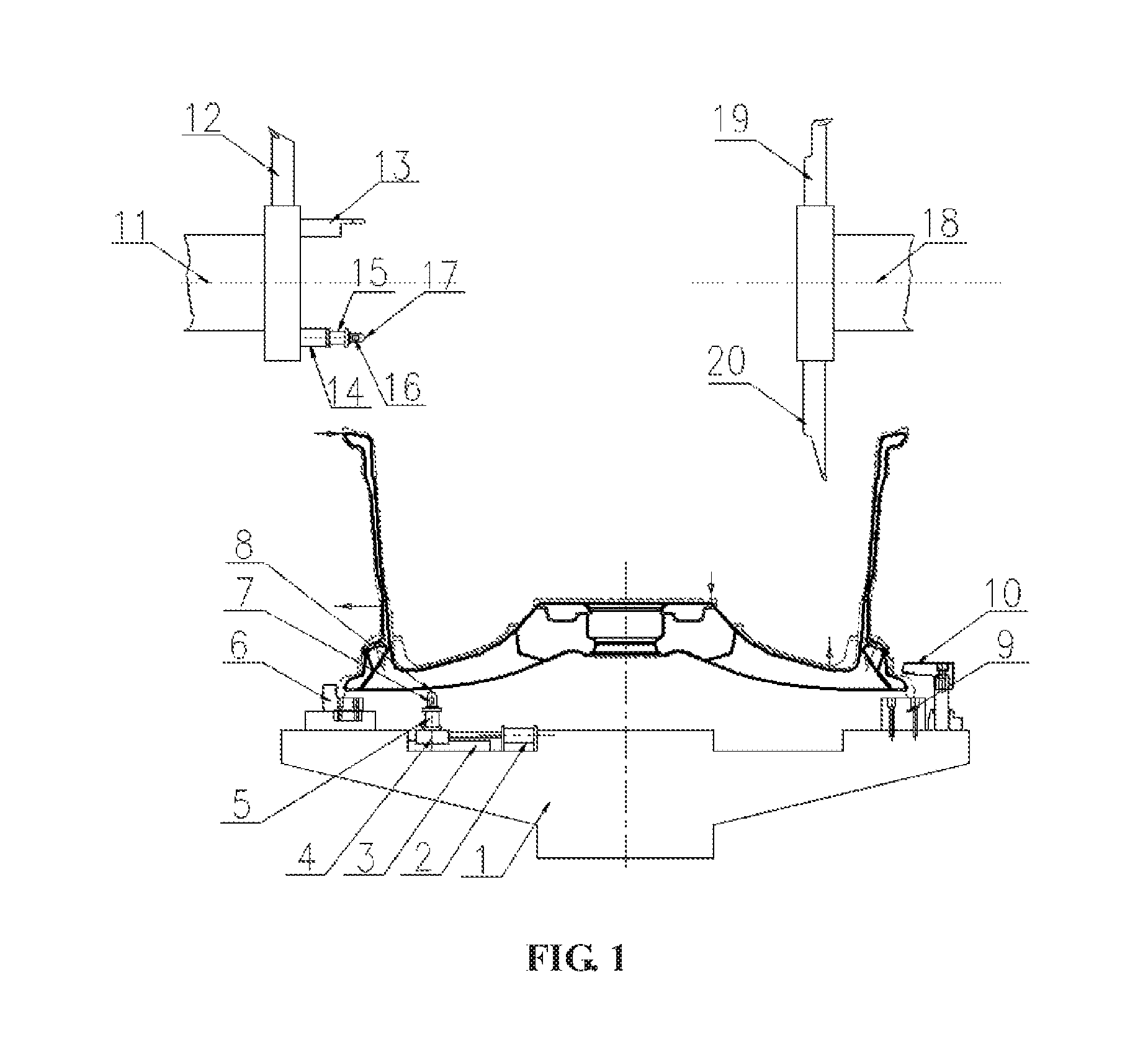
FIG. 1 is a front view of a wheel lightweight machining fixture of the disclosure.
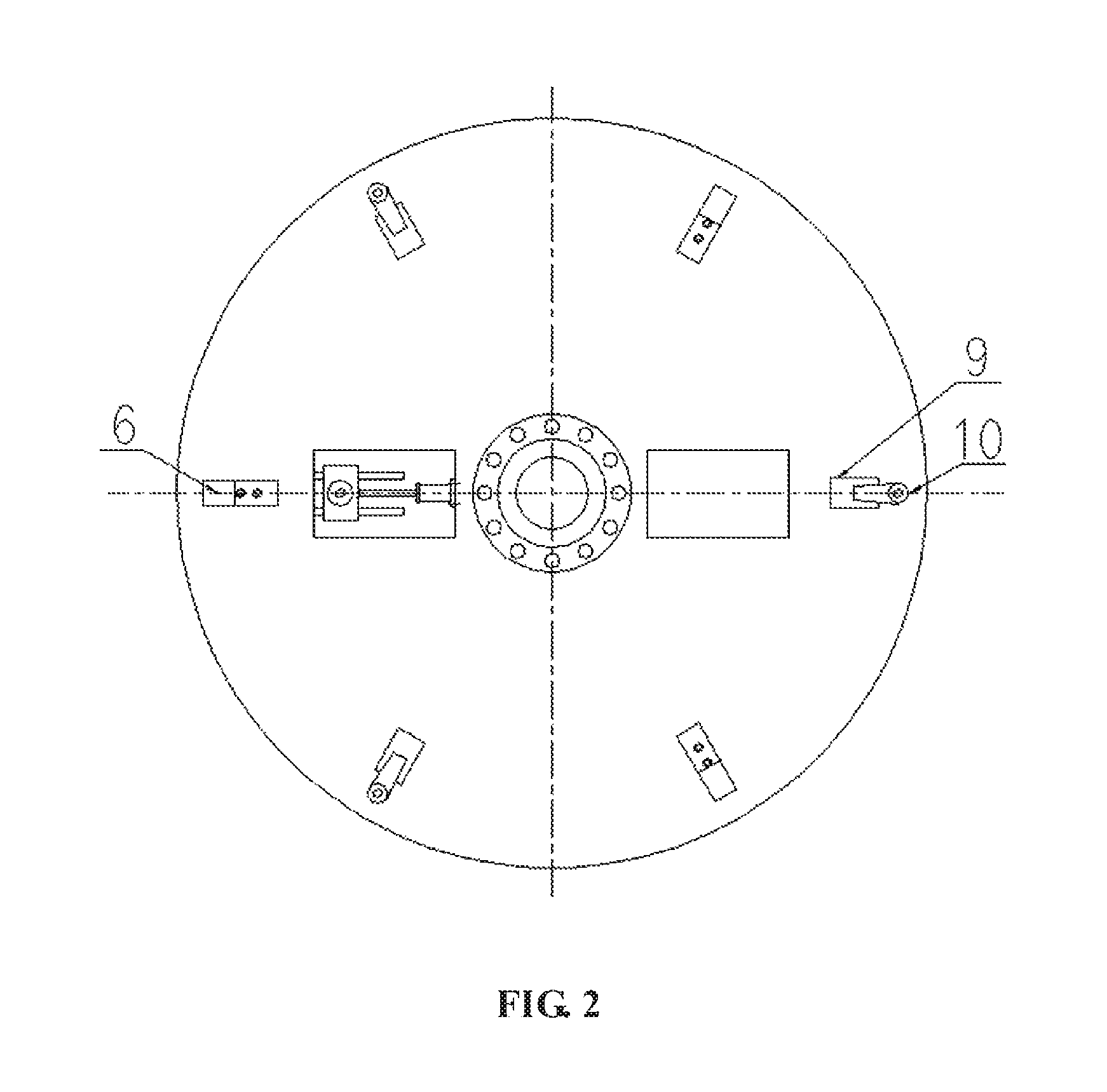
FIG. 2 is a top view of the wheel lightweight machining fixture of the disclosure.
LIST OF REFERENCE SYMBOLS
1 rotating chuck, 2 electric cylinders 3 guide rail 4 slide block 5 first linear motors 6 radial positioning block 7 first piezoelectric sensor 8 first ultrasonic thickness measuring sensor 9 axial positioning block 10 corner cylinder pressure claw 11 first vertical lathe turret 12 inner rim turning tool 13 outer rim turning tool 14 clamping base 15 second linear motor 16 second piezoelectric sensor 17 second ultrasonic thickness measuring sensor 18 second vertical lathe turret 19 central hole flange turning tool 20 spoke back cavity turning tool.
DETAILED DESCRIPTION
Details and works of a specific device provided by the disclosure will be given below in combination with the accompanying drawing and embodiments.
first linear motor, radial positioning blocks, a first piezoelectric sensor, an first ultrasonic thickness measuring sensor, axial positioning blocks, corner cylinder pressure claws, a first vertical lathe turret, an inner rim turning tool, an outer rim turning tool, a clamping base, a second linear motor, a second piezoelectric sensor, an second ultrasonic thickness measuring sensor, a second vertical lathe turret, a central hole flange turning tool and a spoke back cavity turning tool.
Three radial positioning blocks for radial positioning of first stage turning of a wheel, three axial positioning blocks for axial positioning of first stage turning and three corner cylinder pressure claws for pressing the wheel are uniformly distributed on the rotating chuck. Two grooves are bilaterally distributed in the rotating chuck, the electric cylinder and the guide rail are fixedly mounted in the left groove, the slide block is mounted on the guide rail, the output end of the electric cylinder is connected with the slide block, the first linear motor is fixedly mounted on the slide block, the first ultrasonic thickness measuring sensor is mounted at the output end of the first linear motor, and the first piezoelectric sensor is integrated inside the first ultrasonic thickness measuring sensor. When the electric cylinder drives the slide block to move along the guide rail, the position where the first ultrasonic thickness measuring sensor is in contact with a wheel spoke can be adjusted, so that the spoke thicknesses at different positions can be detected.
The inner rim turning tool and the outer rim turning tool are mounted on the first vertical lathe turret for turning the inner rim and outer rim of the wheel. The central hole flange turning tool for turning the central hole and flange surface of the wheel and the spoke back cavity turning tool for turning the spoke back cavity are mounted on the second vertical lathe turret. The clamping base is mounted on the first vertical lathe turret, the second linear motor is mounted on the clamping base, the second ultrasonic thickness measuring sensor is mounted at the output end of the second linear motor, and the second piezoelectric sensor is integrated inside the second ultrasonic thickness measuring sensor. Through motion of the turrets, the second ultrasonic thickness measuring sensor can contact the outer rim of the wheel and detect the rim wall thickness.
A wheel lightweight machining method includes the following procedures.
(1) According to the requirement of the radial detection position of the spoke thickness, the radial position of the first ultrasonic thickness measuring sensor is adjusted via the electric cylinder.
(2) A wheel having the front side downward and the rim upward is clamped onto the rotating chuck, the wheel spoke is required to face the first ultrasonic thickness measuring sensor during clamping.
(3) The wheel is turned by adopting a machining program of wheel size mid-value compilation, the outer rim turning tool on the first vertical lathe turret turns the outer rim, the inner rim turning tool turns the inner rim, the central hole flange turning tool on the second vertical lathe turret turns the central hole and the flange surface, and the spoke back cavity turning tool turns the spoke back cavity.
(4) After turning is completed, the first vertical lathe turret moves, the position of the second ultrasonic thickness measuring sensor is adjusted to face the outer rim of the wheel, then, the second linear motor is started to drive the second ultrasonic thickness measuring sensor to approach the outer rim of the wheel, when the second ultrasonic thickness measuring sensor contacts the outer rim of the wheel, the second piezoelectric sensor picks up a signal, the second linear motor stops moving, and at the moment, the second ultrasonic thickness measuring sensor begins working and detects the rim wall thickness; when the rim wall thickness is detected, the first linear motor is started to drive the first ultrasonic thickness measuring sensor to approach the wheel spoke; when the first ultrasonic thickness measuring sensor contacts the wheel spoke, the first piezoelectric sensor picks up a signal, the second linear motor stops moving, and at the moment, the first ultrasonic thickness measuring sensor begins working and detects the spoke thickness.
(5) A computer compares the detected rim wall thickness and spoke thickness with minimum entity values, and feeds the differences back to a lathe as cutting depths of next precision turning.
(6) After the lathe receives cutting depth instructions, the inner rim turning tool is started to precisely turn the inner rim of the wheel, and the spoke back cavity turning tool is started to precisely turn the spoke back cavity; after precision turning is completed, first stage machining of the wheel is completed, and the rim wall thickness and the spoke thickness undergo minimum entity control.
(7) Finally, the wheel is transferred to a second stage lathe, and after the cap section and the remaining outer rim are turned, turning of the whole wheel is completed.
Embodiment 1
Known is a 17-inch wheel to be machined, the wall thickness of the middle rim is 4.+-.0.25 mm, the spoke is at R120 mm, and the spoke thickness is 30.+-.0.8 mm. The lightweight machining method is as follows.
(1) According to the requirement of the radial detection position (R120 mm) of the spoke thickness, the radial position of the first ultrasonic thickness measuring sensor 8 is adjusted to R120 mm via the electric cylinder 2.
(2) The wheel having the front side downward and the rim upward is clamped onto the rotating chuck 1, in which the wheel spoke is required to face the first ultrasonic thickness measuring sensor 8 during clamping.
(3) The wheel is turned by adopting a machining program of wheel size mid-value compilation, the outer rim turning tool 13 on the first vertical lathe turret 11 turns the outer rim, the inner rim turning tool 12 turns the inner rim, the central hole flange turning tool 19 on the second vertical lathe turret 18 turns the central hole and the flange surface, and the spoke back cavity turning tool 20 turns the spoke back cavity.
(4) After turning is completed, the first vertical lathe turret 11 moves, the position of the second ultrasonic thickness measuring sensor 17 is adjusted to face the outer rim of the wheel, then, the second linear motor 15 is started to drive the second ultrasonic thickness measuring sensor 17 to approach the outer rim of the wheel, when the second ultrasonic thickness measuring sensor 17 contacts the outer rim of the wheel, the second piezoelectric sensor 16 picks up a signal, the second linear motor 15 stops moving, and at the moment, the second ultrasonic thickness measuring sensor 17 begins working and detects the rim wall thickness; when the rim wall thickness is detected, the first linear motor 5 is started to drive the first ultrasonic thickness measuring sensor 8 to approach the wheel spoke; when the first ultrasonic thickness measuring sensor 8 contacts the wheel spoke, the first piezoelectric sensor 7 picks up a signal, the second linear motor 15 stops moving, and at the moment, the first ultrasonic thickness measuring sensor 8 begins working and detects the spoke thickness.
(5) A computer compares the detected rim wall thickness and spoke thickness with minimum entity values, in which the detected rim wall thickness is 3.95 mm, and a difference is drawn from the minimum entity size 3.75 mm; the difference 0.2 mm is fed back to a lathe as a cutting depth of next precision turning of the inner rim; the detected spoke thickness is 30.1 mm, and a difference is drawn from the minimum entity size 29.2 mm; the difference 0.9 mm is fed back to the lathe as a cutting depth of next precision turning of the spoke back cavity.
(6) After the lathe receives cutting depth 0.2 mm and 0.9 mm instructions, the inner rim turning tool 12 is started to precisely turn the inner rim of the wheel, and the spoke back cavity turning tool 20 is started to precisely turn the spoke back cavity; after precision turning is completed, first stage machining of the wheel is completed, and the rim wall thickness and the spoke thickness undergo minimum entity control.
(7) Finally, the wheel is transferred to a second stage lathe, and after the cap section and the remaining outer rim are turned, turning of the whole wheel is completed.
* * * * *
D00000
D00001
D00002
XML
uspto.report is an independent third-party trademark research tool that is not affiliated, endorsed, or sponsored by the United States Patent and Trademark Office (USPTO) or any other governmental organization. The information provided by uspto.report is based on publicly available data at the time of writing and is intended for informational purposes only.
While we strive to provide accurate and up-to-date information, we do not guarantee the accuracy, completeness, reliability, or suitability of the information displayed on this site. The use of this site is at your own risk. Any reliance you place on such information is therefore strictly at your own risk.
All official trademark data, including owner information, should be verified by visiting the official USPTO website at www.uspto.gov. This site is not intended to replace professional legal advice and should not be used as a substitute for consulting with a legal professional who is knowledgeable about trademark law.