Bulk textured material sheeting
Arbesman , et al.
U.S. patent number 10,335,847 [Application Number 15/259,433] was granted by the patent office on 2019-07-02 for bulk textured material sheeting. This patent grant is currently assigned to GRIPMETAL LIMITED. The grantee listed for this patent is Gripmetal Limited. Invention is credited to Ray Arbesman, Winston MacKelvie, Nghi Pham.


| United States Patent | 10,335,847 |
| Arbesman , et al. | July 2, 2019 |
Bulk textured material sheeting
Abstract
A process is provided for making bulk textured material sheeting. As a continuous supply of flat material sheeting is fed, the sheeting is repeatedly impacted with toothed knives, each knife creating a row of raised and generally pointed structures on the sheeting to texture the sheeting.
| Inventors: | Arbesman; Ray (Toronto, CA), Pham; Nghi (Concord, CA), MacKelvie; Winston (Knowlton, CA) | ||||||||||
|---|---|---|---|---|---|---|---|---|---|---|---|
| Applicant: |
|
||||||||||
| Assignee: | GRIPMETAL LIMITED (Dublin,
IE) |
||||||||||
| Family ID: | 49672220 | ||||||||||
| Appl. No.: | 15/259,433 | ||||||||||
| Filed: | September 8, 2016 |
Prior Publication Data
| Document Identifier | Publication Date | |
|---|---|---|
| US 20160375480 A1 | Dec 29, 2016 | |
Related U.S. Patent Documents
| Application Number | Filing Date | Patent Number | Issue Date | ||
|---|---|---|---|---|---|
| 14553741 | Nov 25, 2014 | 9463502 | |||
| PCT/CA2013/000500 | May 23, 2013 | ||||
Foreign Application Priority Data
| May 29, 2012 [CA] | 2778455 | |||
| Current U.S. Class: | 1/1 |
| Current CPC Class: | B21D 31/02 (20130101); B21D 28/10 (20130101); B29C 59/02 (20130101); B21J 5/068 (20200801); B29C 59/022 (20130101); B65H 35/0006 (20130101); Y10T 29/49835 (20150115); Y10T 428/24355 (20150115); Y10T 29/49833 (20150115); Y10T 29/49826 (20150115); B29K 2105/256 (20130101) |
| Current International Class: | B21D 31/02 (20060101); B21J 5/12 (20060101); B29C 59/02 (20060101); B65H 35/00 (20060101); B21D 28/10 (20060101) |
References Cited [Referenced By]
U.S. Patent Documents
| 1897088 | February 1933 | Victor et al. |
| 1915221 | June 1933 | Fitzgerald et al. |
| 2171530 | September 1939 | Balfe et al. |
| 2255268 | September 1941 | Perrine |
| 2781097 | February 1957 | Nold et al. |
| 3092532 | June 1963 | Swick et al. |
| 3134152 | May 1964 | Pei |
| 3170354 | February 1965 | Scholl et al. |
| 3533891 | October 1970 | Wallace et al. |
| 3551232 | December 1970 | Thompson et al. |
| 3557407 | January 1971 | Lemelson |
| 3605360 | September 1971 | Lindal |
| 3615994 | October 1971 | Ian et al. |
| 3677055 | July 1972 | Longhi |
| 4023613 | May 1977 | Uebayasi et al. |
| 4234638 | November 1980 | Yamazoe et al. |
| 4552252 | November 1985 | Stahl et al. |
| 4569424 | February 1986 | Taylor et al. |
| 4640390 | February 1987 | Saumweber et al. |
| 4705278 | November 1987 | Locacius et al. |
| 4723783 | February 1988 | Larsen et al. |
| 4776602 | October 1988 | Gallo et al. |
| 4781389 | November 1988 | Beyer et al. |
| 4815172 | March 1989 | Ward et al. |
| 4911972 | March 1990 | Mercuri et al. |
| 4939818 | July 1990 | Hahn et al. |
| 5067210 | November 1991 | Kayaki |
| 5142743 | September 1992 | Hahn et al. |
| 5143184 | September 1992 | Snyder et al. |
| 5172920 | December 1992 | Schlenk |
| 5362074 | November 1994 | Gallo et al. |
| 5376410 | December 1994 | MacKelvie et al. |
| 5469604 | November 1995 | Calmettes et al. |
| D374609 | October 1996 | Akeno |
| D376533 | December 1996 | Akeno |
| 5611122 | March 1997 | Torigoe et al. |
| 5788247 | August 1998 | Tensor et al. |
| D400427 | November 1998 | Okawa et al. |
| 5842546 | December 1998 | Biswas et al. |
| 5896629 | April 1999 | Van Hooreweder |
| D425405 | May 2000 | Naohara et al. |
| 6247704 | June 2001 | Battistoni et al. |
| 6258457 | July 2001 | Roemmler et al. |
| 6276045 | August 2001 | Paikert et al. |
| 6279222 | August 2001 | Denton et al. |
| 6431331 | August 2002 | Arbesman et al. |
| 6464047 | October 2002 | Arbesman |
| 6622346 | September 2003 | Graham et al. |
| 6671935 | January 2004 | Filion et al. |
| 6843095 | January 2005 | Arbesman |
| 6860368 | March 2005 | Kulis et al. |
| 6910255 | June 2005 | Arbesman |
| 6913673 | July 2005 | Baggot et al. |
| 7048097 | May 2006 | Arbesman |
| 7222701 | May 2007 | Pham et al. |
| 7320386 | January 2008 | Kulis et al. |
| 7686142 | March 2010 | Jung |
| 7841052 | November 2010 | Ducauchuis |
| 7989049 | August 2011 | Potier |
| 8048507 | November 2011 | Shepard et al. |
| 8088316 | January 2012 | Muth et al. |
| D654355 | February 2012 | Cheng |
| 8407864 | April 2013 | Mask et al. |
| 8683840 | April 2014 | Tuma et al. |
| 8685520 | April 2014 | Meyer et al. |
| 9463502 | October 2016 | Arbesman et al. |
| 2001/0001088 | May 2001 | Chesley et al. |
| 2002/0169435 | November 2002 | Neeb et al. |
| 2002/0170789 | November 2002 | Poelemans et al. |
| 2004/0016608 | January 2004 | Gutowski |
| 2004/0140165 | July 2004 | Pham et al. |
| 2005/0170157 | August 2005 | Armela et al. |
| 2006/0027427 | February 2006 | Anda et al. |
| 2006/0087053 | April 2006 | O'Donnell et al. |
| 2006/0118238 | June 2006 | Borazghi |
| 2006/0243017 | November 2006 | Jung et al. |
| 2006/0246256 | November 2006 | Ausen et al. |
| 2008/0003401 | January 2008 | Barnes et al. |
| 2008/0217809 | September 2008 | Zhao et al. |
| 2009/0223753 | September 2009 | Kappagantu et al. |
| 2010/0170758 | July 2010 | Chen et al. |
| 2010/0207334 | August 2010 | Virgin et al. |
| 2011/0051724 | March 2011 | Scott et al. |
| 2011/0079065 | April 2011 | Cabanski et al. |
| 2011/0233875 | September 2011 | Shaver et al. |
| 2011/0260371 | October 2011 | Arora et al. |
| 2012/0003462 | January 2012 | Wong et al. |
| 2012/0006959 | January 2012 | Braun et al. |
| 2013/0152654 | June 2013 | Arbesman et al. |
| 2015/0053517 | February 2015 | Arbesman et al. |
| 2015/0086750 | March 2015 | Arbesman et al. |
| 2015/0099093 | April 2015 | Arbesman et al. |
| 1330521 | Jul 1994 | CA | |||
| 1337622 | Nov 1995 | CA | |||
| 2127339 | Jan 1996 | CA | |||
| 2272115 | Nov 1999 | CA | |||
| 2391183 | Dec 2003 | CA | |||
| 2778455 | Nov 2013 | CA | |||
| 2780397 | Dec 2013 | CA | |||
| 2798303 | Jun 2014 | CA | |||
| 2821897 | Jan 2015 | CA | |||
| 1286625 | Nov 2006 | CN | |||
| 102272471 | Dec 2011 | CN | |||
| 19754740 | Mar 1999 | DE | |||
| 102004048464 | Apr 2006 | DE | |||
| 102006015100 | Oct 2007 | DE | |||
| 102006015145 | Oct 2007 | DE | |||
| 102006015148 | Oct 2007 | DE | |||
| 859163 | Aug 1998 | EP | |||
| 0934820 | Aug 1999 | EP | |||
| 2125126 | Feb 1984 | GB | |||
| 2359186 | Aug 2001 | GB | |||
| 2507128 | Apr 2014 | GB | |||
| 48072067 | Sep 1973 | JP | |||
| 49126532 | Dec 1974 | JP | |||
| 05285561 | Nov 1993 | JP | |||
| 8021462 | Jan 1996 | JP | |||
| 11309524 | Nov 1999 | JP | |||
| 2001001058 | Jan 2001 | JP | |||
| 2002537527 | Nov 2002 | JP | |||
| 2003154423 | May 2003 | JP | |||
| 2013089799 | May 2013 | JP | |||
| 2010105017 | Sep 2010 | WO | |||
| 2011051724 | May 2011 | WO | |||
| 2013177667 | Dec 2013 | WO | |||
| 2015010183 | Jan 2015 | WO | |||
Other References
|
"Graphite Sheet Gaskets", Environmental Gasket Company Ltd., copyright 2009, 2009, 5 pages. cited by applicant . "Tanged Metal Reinforced Graphite Gasket data sheet", Ningbo Sunwell Fluid Technologies Co., Ltd., 2010, 1 page. cited by applicant . U.S. Appl. No. 14/553,741, "Advisory Action", dated May 16, 2016, 4 pages. cited by applicant . U.S. Appl. No. 14/553,741, "Final Office Action", dated Jan. 22, 2016, 8 pages. cited by applicant . U.S. Appl. No. 14/553,741, "Non-Final Office Action", dated Aug. 10, 2015, 10 pages. cited by applicant . U.S. Appl. No. 14/553,741, "Notice of Allowance", dated Jun. 20, 2016, 2 pages. cited by applicant . U.S. Appl. No. 14/553,741, "Notice of Allowance", dated Jun. 8, 2016, 5 pages. cited by applicant . U.S. Appl. No. 14/553,741, "Restriction Requirement", dated Apr. 6, 2015, 7 pages. cited by applicant . Japanese Application No. JP2015-514294, "Office Action", Apr. 4, 2017, 3 pages. cited by applicant . PCT/CA2013/000500, "International Preliminary Report on Patentability", dated Dec. 11, 2014, 6 pages. cited by applicant . PCT/CA2013/000500, "International Search Report and Written Opinion", dated Aug. 28, 2013, 7 pages. cited by applicant. |
Primary Examiner: Hong; John C
Attorney, Agent or Firm: Brooks Kushman P.C.
Parent Case Text
CROSS-REFERENCE TO RELATED APPLICATIONS
This application is a U.S. continuation application claiming priority to U.S. patent application Ser. No. 14/553,741, filed Nov. 25, 2014, now U.S. Pat. No. 9,463,502, issued Oct. 11, 2016, which claims the priority benefit of International Patent Application No. PCT/CA2013/000500, filed May 23, 2013, which claims the priority benefit of Canadian Patent Application No. 2,778,455, filed May 29, 2012, the contents of which are incorporated by reference herein in their entirety for all intended purposes.
Claims
What is claimed is:
1. A process for making bulk textured material sheeting, comprising: a) feeding a continuous supply of material sheeting to a texturing apparatus; and b) repeatedly impacting the sheeting with toothed knives of the texturing apparatus, each knife creating a row of raised and pointed structures on the sheeting to texture the sheeting; wherein step b) comprises actuating a first one of the knives downward and across the sheeting, and actuating a second one of the knives downward and across the sheeting in an opposing direction; wherein each pointed structure has a finished height of between 150% to 300% of a thickness of the sheeting; and wherein in step b), the sheeting is not perforated.
2. The process of claim 1, wherein the knives are actuated downward and across the sheeting to gouge the pointed structures out of the sheeting.
3. The process of claim 1, wherein the row created by at least one of the knives is continuous and substantially spans a width of the sheeting.
4. The process of claim 1, wherein the knives are arranged in one or more packs to form several rows of pointed structures in a single stroke.
5. The process of claim 1, wherein step b) comprises creating pointed structures on first and second opposed sides of the sheeting.
6. The process of claim 1, further comprising taking up the textured sheeting in a take up reel after the step b).
7. The process of claim 1, wherein step b) comprises actuating a first set of the knives generally downward and across the sheeting, and actuating a second set of the knives generally downward and across the sheeting in the opposing direction.
Description
FIELD OF THE INVENTION
The invention relates to material surface texturing, and more specifically relates to processes for making bulk textured material sheeting.
BACKGROUND OF THE INVENTION
Laminates are popular in various applications (e.g. building materials, panels for automotive applications, large scale industrial parts). In making laminated materials, it is common to use adhesive to join the lamina. However, adhesives have many known deficiencies. They are expensive, messy and emit noxious fumes. Many typical adhesives used for laminating heterogeneous materials are also prone to failure or shattering/cracking under various stresses (temperature, bending, cutting). Further, adhesives are undesirable from an environmental point of view as they foul the underlying materials and prevent recycling or reclamation of the lamina. It would be desirable to avoid the use of adhesive without compromising the strength of the laminate.
Mechanical attachment in individual parts (e.g. brake backing plate to friction material) has become known and highly successful, but the process is used on relatively thick steel in heavy individual plates, not on a continuous larger scale material that could be used for making adhesive-less laminated materials, including laminates of thinner materials.
Further, at present, individual parts are limited in terms of the size and shape variations that are possible. In order to provide mechanical attachment on individual parts, the blanks are typically fed from a magazine in which they all must be of a uniform size and outline. This is not convenient for larger scale applications, or one-off sizes, or custom lengths, which may be desirable for use in building materials, in particular.
It would be desirable to have a continuous process for preparing a textured (mechanical-attachment-ready) surface on bulk material.
SUMMARY OF THE INVENTION
A process is provided for making bulk textured material sheeting. As a continuous supply of flat material sheeting is fed, the sheeting is repeatedly impacted with toothed knives, each knife creating a row of raised and generally pointed structures on the sheeting to texture the sheeting. Preferably, the knives are actuated generally downward and across the sheeting to gouge the pointed structures out of the sheeting. The pointed structures may have a tilted or hooked shape. The hook, in one embodiment, is curled or twisted from the axis of its row. The hook shape is determined by the shape of the teeth on the knives, and the knives' path of travel. Preferably, no further (secondary) operation is needed to produce the hooked shape.
Preferably, the knives are arranged such that the knives are capable of forming a continuous row of pointed structures substantially spanning the width of the sheeting. Preferably, a single knife is capable of forming a continuous row of pointed structures substantially spanning the width of the sheeting. Preferably, the knives are arranged in one or more packs to form several rows of pointed structures in a single impact or stroke.
The process may include detecting an end of the supply and stopping the impact operation.
Preferably, the rows are formed substantially without gaps along the entire length of the sheet. Various patterns, arrangements, densities and dimensions of projections are possible. In one embodiment, each pointed structure has a finished height of less than 0.0100''. The pointed structure dimensions may be based on a tiered scale of hook grades for different applications, such as:
Super-max. hook height 0.070''
Regular-max. hook height 0.060''
Mini-max. hook height 0.045''
Micro-max. hook height 0.030''
Preferably, in this embodiment, each pointed structure has a finished thickness at its base of less than 0.050'', and more preferably, less than 0.040''. Preferably, in this embodiment, each pointed structure has a finished height between about 150% to about 300% of the thickness of the sheeting (and not higher than the maximum height of each type of hook as appropriate). Preferably, in this embodiment, the density of pointed structures on the sheeting is between approximately 30-200 pointed structures per square inch, or more preferably, approximately 40 hooks per square inch for Super and Regular; 80 hooks per square inch for Mini; 190 hooks per square inch for Micro. Nonetheless, a great variety of dimensions and geometries of hooks are possible. Further, the hooks need not be provided in precisely matching rows over the entire material, but may be formed in zones or patterns to suit a particular application.
A two-sided process is also possible, in which the impact of the knives causes pointed structures to be formed on both sides of the sheeting.
Various post-texturing steps are possible. The textured sheeting may be simply taken up in a coil after the impacting step. The textured sheeting may be cut into lengths or strips after the impacting step. The textured sheeting may be fed directly to a joining station for joining the textured sheeting to another material. Other forming and shaping options exist. For instance, the textured sheeting may be roll-formed or bent to make tubes (round or otherwise), or channels, corners or other shapes.
Various end-products are possible from the textured sheeting material: coiled material, textured material pieces, joined material composite/laminate, shaped, rolled or bent material sheeting pieces or lengths.
The mechanical attachment allows heterogeneous materials to be joined in a laminate thereby combining and enhancing the properties of each material (e.g. adding strength or stiffness from a thin metal backing to a plastic, rubbery, or brittle top layer). This can also be used to make very strong, lightweight materials, as the individual components can be very thin, but the overall assembled structure has considerable strength due to the locking power of the embedded hooks that prevents the material from easily flexing or bending. This can also reduce the need for expensive or exotic materials as the properties of two or more possibly lower-grade (or recycled) materials can be easily combined to have more desirable characteristics. The laminated material itself can also be formed and stamped, preferably by first heating to at least partially soften any non-metallic lamina.
Textured bulk material may have other uses besides making laminated end products. The material may be used on its own as a cut-to-length construction material where the textured surface provides an anti-skid or attachment-ready surface (e.g. to receive a bulk second layer at the point of installation). Hooks on the surface provide a useful surface texture to receive and grab materials (e.g. fibrous materials where the hooks both embed and trap fibres thereof).
Thin straps of the material may also be used like a tape for bundling or securing loose or weak materials (the hooks are readily embedded by pressing the strap into and around the bundle or material to "stick" it together and secure it).
BRIEF DESCRIPTION OF THE DRAWINGS
FIG. 1 shows a single-sided texturing process.
FIG. 2 shows a double-sided texturing process.
FIG. 3 shows a plan view of a sample apparatus used to provide single-sided texturing.
FIG. 4 shows a finished roll of bulk single-sided textured material sheeting.
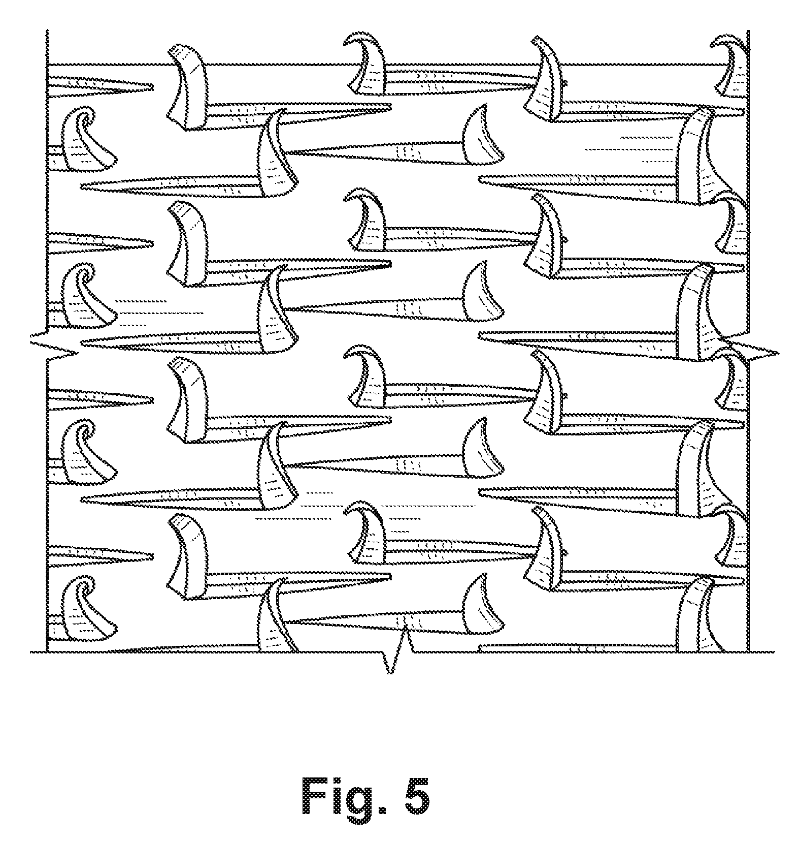
FIG. 5 shows a close-up of the texture of FIG. 3.
DETAILED DESCRIPTION
A process is provided for making bulk textured material sheeting. As a continuous supply of flat material sheeting is fed, the sheeting is repeatedly impacted with toothed knives, each knife creating a row of raised and generally pointed (nail-like) structures on the sheeting to texture the sheeting.
The process is shown in summary form in FIG. 1. A feed mechanism draws the material 2 from a self-wound coil 1 (or supply reel). The material is fed into an apparatus 3 for texturing. The apparatus uses knives (not shown) to impact the material and raise pointed structures on its surface. The material emerges from the apparatus now bearing pointed structures. This textured material 4 is then guided into a coil 5 (or onto a take-up reel).
As shown in FIG. 2, the material 2 may also be textured on both sides. A feed mechanism draws the material 2 from the self-wound coil 1 (or supply reel). The material is fed into a modified apparatus 3, that includes opposed impacting sections (knives disposed on both sides of the material--not shown). The material emerges from the apparatus now bearing pointed structures on both sides. This textured material 4 is then guided into a coil 5 (or onto a take-up reel).
Alternatively, a roll of single-sided textured material 4 may be run through the apparatus a second time to texture the opposing face using appropriate support to protect the first face's pointed structures.
As shown in FIG. 5, the pointed structures may be in the form of hooks. Each hook is integrally formed from the material itself that is gouged or scraped up from the surface of the material by the impacting knives. The hooks are not punched through from the opposing side, so the underlying material is not punctured or perforated, but retains the integrity of its continuous body. Detail of the pointed structures (here, hooks) is shown in FIG. 4. The apparatus and tooling can be modified to form various shapes, dimensions and densities of hooks, depending on the material requirements and tolerances.
The knives of the apparatus are preferably in a pack with opposing knives being positioned offset from each other (i.e. an "A" set of knives and a "B" set of knives interleaved with each other in a pack, with the "A" set extended out to one side and the "B" set extended out to the other side). Side impacts from the apparatus force the "A" and "B" sets toward each other, so that the teeth of the knives gouge or scrape up hooks from the surface of the material.
Various types of apparatus may be used to drive the knives and form the hooks. One useful embodiment uses a press to actuate the toothed knives generally into and across the surface of the material sheeting. As shown in FIG. 3, apparatus 3 includes an upper die plate 13 (this may be mounted in a press, or be part of a free standing assembly actuated by an independent press--as in CA 2,760,923, filed on Dec. 6, 2011, publication forthcoming). Transverse slide rods 16 are suspended from the apparatus and slide within slots in the knives 10. Return springs (not shown) are connected to the slide rods to bias the slide rods toward each other. A pressure plate 19 is disposed above the knives. Two block housings 21 are mounted transversely on the upper die plate adjacent to the edges of the knives. A drive block 22 is mounted on each block housing by slide bolt 23, which is disposed substantially parallel to the longitudinal axis of the knives. A slide block 24 is slidably mounted in each housing adjacent to the drive block.
In operation, a press (not shown) drives upper die plate 13 of the apparatus 3 onto the material that has been fed into a material strike zone below knives 10. The force of the press causes the slide block 24 to impact the bottom surface of the press (not shown) before the knives 10 impact the surface of the material. The impact against the bottom surface of the material drives the slide block up relative to the drive block 22, causing the angled surface of 24 to exert a force on the drive block in a direction substantially parallel to the longitudinal axis of the knives. This force causes each drive block to move separate individual knives in the pack in opposing directions along their respective longitudinal axes. Because only alternate knives contact each drive block before impact, adjacent knives are pushed in opposite directions by each drive block. Preferably, the knives are moving before contact with the material surface.
The teeth 11 of the knives are pushed down into the material, and the knives also slide along slide rods 16 parallel to their longitudinal axes. These simultaneous downward and sliding movements cause each tooth 11 of a knife to form one pointed structure (hook).
After the press lifts, the slide block 24 is returned to its starting position by compress springs 20, and the knives 10 and drive block 22 are returned to their starting positions by other springs (not shown). The knives are withdrawn from the material, which is then advanced by the feed mechanism (in a progression) to form another textured section.
FIGS. 4 and 5 show a possible embodiment of the textured material sheeting in finished form. As shown, the material may be coiled onto itself (or on a take-up reel) and sold as a bulk (mechanical-attachment-ready) material.
The finished material can be cut into specific products or combined with one or more heterogeneous materials in a double- or multi-ply laminate.
Material may also be directed to other downstream operations (e.g. stamping into shaped parts/strips/pieces, joining with one or more heterogeneous materials in a laminate, or other forming. The bulk material in one embodiment may be roll-formed or bent to take on a three-dimensional shape (e.g. cylindrical or other shaped tube).
Various ductile materials can be used with this process. Although metal sheeting is shown in FIGS. 4 and 5, the process has also be found to work on various harder plastics (Shore hardness of approximately D55 and up) and other materials in a range of widths and thicknesses. The sheeting can also be cooled or heated prior to impacting in order to make it more ductile or otherwise amenable to the texturing operation. For example, soft and rubbery materials (including those below the suggested Shore hardness of D55) may be cooled or frozen to apply this process.
Further, although the material may be selected to retain and hold an upstanding pointed structure as taught and shown, there may also be advantages in processing material according to this method where the hooks do not stay raised, but collapse on themselves. The process may be advantageous simply for roughening or providing a disturbed surface on a material.
The foregoing description illustrates only certain preferred embodiments of the invention. The invention is not limited to the foregoing examples. That is, persons skilled in the art will appreciate and understand that modifications and variations are, or will be, possible to utilize and carry out the teachings of the invention described herein. The scope of the claims should not be limited by the preferred embodiments set forth in the examples, but should be given the broadest purposive construction consistent with the description as a whole.
* * * * *
D00000
D00001
D00002
D00003
D00004
XML
uspto.report is an independent third-party trademark research tool that is not affiliated, endorsed, or sponsored by the United States Patent and Trademark Office (USPTO) or any other governmental organization. The information provided by uspto.report is based on publicly available data at the time of writing and is intended for informational purposes only.
While we strive to provide accurate and up-to-date information, we do not guarantee the accuracy, completeness, reliability, or suitability of the information displayed on this site. The use of this site is at your own risk. Any reliance you place on such information is therefore strictly at your own risk.
All official trademark data, including owner information, should be verified by visiting the official USPTO website at www.uspto.gov. This site is not intended to replace professional legal advice and should not be used as a substitute for consulting with a legal professional who is knowledgeable about trademark law.